EP3298267B1 - Brennkraftmaschine mit einem elektromotor - Google Patents
Brennkraftmaschine mit einem elektromotor Download PDFInfo
- Publication number
- EP3298267B1 EP3298267B1 EP16735816.7A EP16735816A EP3298267B1 EP 3298267 B1 EP3298267 B1 EP 3298267B1 EP 16735816 A EP16735816 A EP 16735816A EP 3298267 B1 EP3298267 B1 EP 3298267B1
- Authority
- EP
- European Patent Office
- Prior art keywords
- combustion engine
- internal combustion
- cylinder head
- electric motor
- crankcase
- Prior art date
- Legal status (The legal status is an assumption and is not a legal conclusion. Google has not performed a legal analysis and makes no representation as to the accuracy of the status listed.)
- Active
Links
Images



Classifications
-
- F—MECHANICAL ENGINEERING; LIGHTING; HEATING; WEAPONS; BLASTING
- F02—COMBUSTION ENGINES; HOT-GAS OR COMBUSTION-PRODUCT ENGINE PLANTS
- F02N—STARTING OF COMBUSTION ENGINES; STARTING AIDS FOR SUCH ENGINES, NOT OTHERWISE PROVIDED FOR
- F02N11/00—Starting of engines by means of electric motors
- F02N11/04—Starting of engines by means of electric motors the motors being associated with current generators
-
- B—PERFORMING OPERATIONS; TRANSPORTING
- B60—VEHICLES IN GENERAL
- B60K—ARRANGEMENT OR MOUNTING OF PROPULSION UNITS OR OF TRANSMISSIONS IN VEHICLES; ARRANGEMENT OR MOUNTING OF PLURAL DIVERSE PRIME-MOVERS IN VEHICLES; AUXILIARY DRIVES FOR VEHICLES; INSTRUMENTATION OR DASHBOARDS FOR VEHICLES; ARRANGEMENTS IN CONNECTION WITH COOLING, AIR INTAKE, GAS EXHAUST OR FUEL SUPPLY OF PROPULSION UNITS IN VEHICLES
- B60K25/00—Auxiliary drives
- B60K25/02—Auxiliary drives directly from an engine shaft
-
- B—PERFORMING OPERATIONS; TRANSPORTING
- B60—VEHICLES IN GENERAL
- B60K—ARRANGEMENT OR MOUNTING OF PROPULSION UNITS OR OF TRANSMISSIONS IN VEHICLES; ARRANGEMENT OR MOUNTING OF PLURAL DIVERSE PRIME-MOVERS IN VEHICLES; AUXILIARY DRIVES FOR VEHICLES; INSTRUMENTATION OR DASHBOARDS FOR VEHICLES; ARRANGEMENTS IN CONNECTION WITH COOLING, AIR INTAKE, GAS EXHAUST OR FUEL SUPPLY OF PROPULSION UNITS IN VEHICLES
- B60K6/00—Arrangement or mounting of plural diverse prime-movers for mutual or common propulsion, e.g. hybrid propulsion systems comprising electric motors and internal combustion engines
- B60K6/20—Arrangement or mounting of plural diverse prime-movers for mutual or common propulsion, e.g. hybrid propulsion systems comprising electric motors and internal combustion engines the prime-movers consisting of electric motors and internal combustion engines, e.g. HEVs
- B60K6/22—Arrangement or mounting of plural diverse prime-movers for mutual or common propulsion, e.g. hybrid propulsion systems comprising electric motors and internal combustion engines the prime-movers consisting of electric motors and internal combustion engines, e.g. HEVs characterised by apparatus, components or means specially adapted for HEVs
- B60K6/26—Arrangement or mounting of plural diverse prime-movers for mutual or common propulsion, e.g. hybrid propulsion systems comprising electric motors and internal combustion engines the prime-movers consisting of electric motors and internal combustion engines, e.g. HEVs characterised by apparatus, components or means specially adapted for HEVs characterised by the motors or the generators
-
- B—PERFORMING OPERATIONS; TRANSPORTING
- B60—VEHICLES IN GENERAL
- B60K—ARRANGEMENT OR MOUNTING OF PROPULSION UNITS OR OF TRANSMISSIONS IN VEHICLES; ARRANGEMENT OR MOUNTING OF PLURAL DIVERSE PRIME-MOVERS IN VEHICLES; AUXILIARY DRIVES FOR VEHICLES; INSTRUMENTATION OR DASHBOARDS FOR VEHICLES; ARRANGEMENTS IN CONNECTION WITH COOLING, AIR INTAKE, GAS EXHAUST OR FUEL SUPPLY OF PROPULSION UNITS IN VEHICLES
- B60K6/00—Arrangement or mounting of plural diverse prime-movers for mutual or common propulsion, e.g. hybrid propulsion systems comprising electric motors and internal combustion engines
- B60K6/20—Arrangement or mounting of plural diverse prime-movers for mutual or common propulsion, e.g. hybrid propulsion systems comprising electric motors and internal combustion engines the prime-movers consisting of electric motors and internal combustion engines, e.g. HEVs
- B60K6/22—Arrangement or mounting of plural diverse prime-movers for mutual or common propulsion, e.g. hybrid propulsion systems comprising electric motors and internal combustion engines the prime-movers consisting of electric motors and internal combustion engines, e.g. HEVs characterised by apparatus, components or means specially adapted for HEVs
- B60K6/40—Arrangement or mounting of plural diverse prime-movers for mutual or common propulsion, e.g. hybrid propulsion systems comprising electric motors and internal combustion engines the prime-movers consisting of electric motors and internal combustion engines, e.g. HEVs characterised by apparatus, components or means specially adapted for HEVs characterised by the assembly or relative disposition of components
-
- B—PERFORMING OPERATIONS; TRANSPORTING
- B60—VEHICLES IN GENERAL
- B60K—ARRANGEMENT OR MOUNTING OF PROPULSION UNITS OR OF TRANSMISSIONS IN VEHICLES; ARRANGEMENT OR MOUNTING OF PLURAL DIVERSE PRIME-MOVERS IN VEHICLES; AUXILIARY DRIVES FOR VEHICLES; INSTRUMENTATION OR DASHBOARDS FOR VEHICLES; ARRANGEMENTS IN CONNECTION WITH COOLING, AIR INTAKE, GAS EXHAUST OR FUEL SUPPLY OF PROPULSION UNITS IN VEHICLES
- B60K6/00—Arrangement or mounting of plural diverse prime-movers for mutual or common propulsion, e.g. hybrid propulsion systems comprising electric motors and internal combustion engines
- B60K6/20—Arrangement or mounting of plural diverse prime-movers for mutual or common propulsion, e.g. hybrid propulsion systems comprising electric motors and internal combustion engines the prime-movers consisting of electric motors and internal combustion engines, e.g. HEVs
- B60K6/42—Arrangement or mounting of plural diverse prime-movers for mutual or common propulsion, e.g. hybrid propulsion systems comprising electric motors and internal combustion engines the prime-movers consisting of electric motors and internal combustion engines, e.g. HEVs characterised by the architecture of the hybrid electric vehicle
- B60K6/48—Parallel type
-
- F—MECHANICAL ENGINEERING; LIGHTING; HEATING; WEAPONS; BLASTING
- F01—MACHINES OR ENGINES IN GENERAL; ENGINE PLANTS IN GENERAL; STEAM ENGINES
- F01P—COOLING OF MACHINES OR ENGINES IN GENERAL; COOLING OF INTERNAL-COMBUSTION ENGINES
- F01P11/00—Component parts, details, or accessories not provided for in, or of interest apart from, groups F01P1/00 - F01P9/00
- F01P11/08—Arrangements of lubricant coolers
-
- F—MECHANICAL ENGINEERING; LIGHTING; HEATING; WEAPONS; BLASTING
- F02—COMBUSTION ENGINES; HOT-GAS OR COMBUSTION-PRODUCT ENGINE PLANTS
- F02D—CONTROLLING COMBUSTION ENGINES
- F02D45/00—Electrical control not provided for in groups F02D41/00 - F02D43/00
-
- F—MECHANICAL ENGINEERING; LIGHTING; HEATING; WEAPONS; BLASTING
- F02—COMBUSTION ENGINES; HOT-GAS OR COMBUSTION-PRODUCT ENGINE PLANTS
- F02M—SUPPLYING COMBUSTION ENGINES IN GENERAL WITH COMBUSTIBLE MIXTURES OR CONSTITUENTS THEREOF
- F02M39/00—Arrangements of fuel-injection apparatus with respect to engines; Pump drives adapted to such arrangements
-
- F—MECHANICAL ENGINEERING; LIGHTING; HEATING; WEAPONS; BLASTING
- F02—COMBUSTION ENGINES; HOT-GAS OR COMBUSTION-PRODUCT ENGINE PLANTS
- F02M—SUPPLYING COMBUSTION ENGINES IN GENERAL WITH COMBUSTIBLE MIXTURES OR CONSTITUENTS THEREOF
- F02M39/00—Arrangements of fuel-injection apparatus with respect to engines; Pump drives adapted to such arrangements
- F02M39/02—Arrangements of fuel-injection apparatus to facilitate the driving of pumps; Arrangements of fuel-injection pumps; Pump drives
-
- F—MECHANICAL ENGINEERING; LIGHTING; HEATING; WEAPONS; BLASTING
- F02—COMBUSTION ENGINES; HOT-GAS OR COMBUSTION-PRODUCT ENGINE PLANTS
- F02M—SUPPLYING COMBUSTION ENGINES IN GENERAL WITH COMBUSTIBLE MIXTURES OR CONSTITUENTS THEREOF
- F02M63/00—Other fuel-injection apparatus having pertinent characteristics not provided for in groups F02M39/00 - F02M57/00 or F02M67/00; Details, component parts, or accessories of fuel-injection apparatus, not provided for in, or of interest apart from, the apparatus of groups F02M39/00 - F02M61/00 or F02M67/00; Combination of fuel pump with other devices, e.g. lubricating oil pump
- F02M63/02—Fuel-injection apparatus having several injectors fed by a common pumping element, or having several pumping elements feeding a common injector; Fuel-injection apparatus having provisions for cutting-out pumps, pumping elements, or injectors; Fuel-injection apparatus having provisions for variably interconnecting pumping elements and injectors alternatively
- F02M63/0225—Fuel-injection apparatus having a common rail feeding several injectors ; Means for varying pressure in common rails; Pumps feeding common rails
- F02M63/0275—Arrangement of common rails
-
- F—MECHANICAL ENGINEERING; LIGHTING; HEATING; WEAPONS; BLASTING
- F02—COMBUSTION ENGINES; HOT-GAS OR COMBUSTION-PRODUCT ENGINE PLANTS
- F02N—STARTING OF COMBUSTION ENGINES; STARTING AIDS FOR SUCH ENGINES, NOT OTHERWISE PROVIDED FOR
- F02N15/00—Other power-operated starting apparatus; Component parts, details, or accessories, not provided for in, or of interest apart from groups F02N5/00 - F02N13/00
- F02N15/006—Assembling or mounting of starting devices
-
- B—PERFORMING OPERATIONS; TRANSPORTING
- B60—VEHICLES IN GENERAL
- B60K—ARRANGEMENT OR MOUNTING OF PROPULSION UNITS OR OF TRANSMISSIONS IN VEHICLES; ARRANGEMENT OR MOUNTING OF PLURAL DIVERSE PRIME-MOVERS IN VEHICLES; AUXILIARY DRIVES FOR VEHICLES; INSTRUMENTATION OR DASHBOARDS FOR VEHICLES; ARRANGEMENTS IN CONNECTION WITH COOLING, AIR INTAKE, GAS EXHAUST OR FUEL SUPPLY OF PROPULSION UNITS IN VEHICLES
- B60K6/00—Arrangement or mounting of plural diverse prime-movers for mutual or common propulsion, e.g. hybrid propulsion systems comprising electric motors and internal combustion engines
- B60K6/20—Arrangement or mounting of plural diverse prime-movers for mutual or common propulsion, e.g. hybrid propulsion systems comprising electric motors and internal combustion engines the prime-movers consisting of electric motors and internal combustion engines, e.g. HEVs
- B60K6/22—Arrangement or mounting of plural diverse prime-movers for mutual or common propulsion, e.g. hybrid propulsion systems comprising electric motors and internal combustion engines the prime-movers consisting of electric motors and internal combustion engines, e.g. HEVs characterised by apparatus, components or means specially adapted for HEVs
- B60K6/26—Arrangement or mounting of plural diverse prime-movers for mutual or common propulsion, e.g. hybrid propulsion systems comprising electric motors and internal combustion engines the prime-movers consisting of electric motors and internal combustion engines, e.g. HEVs characterised by apparatus, components or means specially adapted for HEVs characterised by the motors or the generators
- B60K2006/268—Electric drive motor starts the engine, i.e. used as starter motor
-
- B—PERFORMING OPERATIONS; TRANSPORTING
- B60—VEHICLES IN GENERAL
- B60Y—INDEXING SCHEME RELATING TO ASPECTS CROSS-CUTTING VEHICLE TECHNOLOGY
- B60Y2200/00—Type of vehicle
- B60Y2200/90—Vehicles comprising electric prime movers
- B60Y2200/92—Hybrid vehicles
-
- F—MECHANICAL ENGINEERING; LIGHTING; HEATING; WEAPONS; BLASTING
- F02—COMBUSTION ENGINES; HOT-GAS OR COMBUSTION-PRODUCT ENGINE PLANTS
- F02D—CONTROLLING COMBUSTION ENGINES
- F02D2400/00—Control systems adapted for specific engine types; Special features of engine control systems not otherwise provided for; Power supply, connectors or cabling for engine control systems
- F02D2400/21—Engine cover with integrated cabling
-
- F—MECHANICAL ENGINEERING; LIGHTING; HEATING; WEAPONS; BLASTING
- F02—COMBUSTION ENGINES; HOT-GAS OR COMBUSTION-PRODUCT ENGINE PLANTS
- F02N—STARTING OF COMBUSTION ENGINES; STARTING AIDS FOR SUCH ENGINES, NOT OTHERWISE PROVIDED FOR
- F02N11/00—Starting of engines by means of electric motors
- F02N11/08—Circuits specially adapted for starting of engines
- F02N2011/0881—Components of the circuit not provided for by previous groups
- F02N2011/0896—Inverters for electric machines, e.g. starter-generators
-
- Y—GENERAL TAGGING OF NEW TECHNOLOGICAL DEVELOPMENTS; GENERAL TAGGING OF CROSS-SECTIONAL TECHNOLOGIES SPANNING OVER SEVERAL SECTIONS OF THE IPC; TECHNICAL SUBJECTS COVERED BY FORMER USPC CROSS-REFERENCE ART COLLECTIONS [XRACs] AND DIGESTS
- Y02—TECHNOLOGIES OR APPLICATIONS FOR MITIGATION OR ADAPTATION AGAINST CLIMATE CHANGE
- Y02T—CLIMATE CHANGE MITIGATION TECHNOLOGIES RELATED TO TRANSPORTATION
- Y02T10/00—Road transport of goods or passengers
- Y02T10/60—Other road transportation technologies with climate change mitigation effect
- Y02T10/62—Hybrid vehicles
Definitions
- the invention relates to an internal combustion engine with at least one electric motor according to the preamble of claim 1.
- Such an internal combustion engine is from the DE 10 2013 020 440 A1 known.
- the object of the present invention is to integrate these components into the combustion engine in such a way as to cover the multitude of possible customer applications with or without special transmission variants and to expand the customer spectrum for the future.
- a further advantageous embodiment provides that one of the at least one electric motor is designed as a generator. This has the advantage that surplus energy can be stored, for example, in batteries.
- Another advantageous embodiment provides for a common rail to be arranged in a cylinder head cover of the internal combustion engine. This offers advantages in terms of installation space and assembly.
- An advantageous embodiment provides for a wiring harness to be located in the cylinder head cover. This also offers advantages in terms of installation space and assembly.
- a further advantageous embodiment provides for the control unit to be mounted on or at the cylinder head cover. This also offers advantages in terms of installation space and assembly.
- control unit is connected wirelessly to the wiring harness integrated in the cylinder head cover. This also offers advantages in terms of installation space, assembly, and service.
- An advantageous embodiment provides for an engine oil cooler to be arranged laterally on the crankcase at approximately the same height and spatially behind one of the at least one electric motor, in particular on an exhaust side of the internal combustion engine. This offers advantages in terms of installation space, assembly, and service.
- a further advantageous embodiment provides for an exhaust gas recirculation (EGR) module to be arranged on the side of the crankcase above the engine oil cooler, particularly on the exhaust side of the internal combustion engine.
- EGR exhaust gas recirculation
- Another advantageous embodiment provides for a high-pressure pump to be arranged laterally on the cylinder head, particularly on a service side of the internal combustion engine, in such a way that it can be connected without wires to a common rail located in the cylinder head cover. This offers advantages in terms of installation space, assembly, and service.
- At least one hydraulic pump is arranged below the electric motor arranged laterally on the crankcase and, like the electric motor, is arranged via a gear to the front-side gear drive This offers advantages in terms of installation space, assembly, and service, and increases application possibilities.
- crankcase with defined power transmission.
- the front cover function is integrated into the crankcase.
- Reinforced drivetrain and gear train with special bearings (the crankshaft faces the flywheel and the rim, respectively), and the engine is designed for the monobloc construction as a load-bearing unit for forward, reverse, and sideways transmission. (together with a cast oil pan, the engine becomes a load-bearing component);
- connection options for various hybrid systems for the industrial sector are available; the design is compatible with combustion engines with different numbers of cylinders, e.g., 4 and 6 (the external geometry of the torsional vibration damper features functional separation); adaptation of the coolant and oil circuits, optimized with regard to pressure loss; multifunctional auxiliary gearbox for high-speed electric motor and PTO with clutch and lineless oil supply via plug-in connections; beltless motor with fully electrified ancillary units as an option; consistent functional separation and distribution of system components according to strict safety criteria and service requirements for the best possible customer benefit.
- the high-pressure pump is surrounded by a sound, kick or impact protection cage.
- the invention relates to the entire coordinated and interlocking arrangement of the system components.
- all key assemblies are segmented and recombined in such a way that a very high functional density can be achieved with optimal and compact use of installation space.
- Figure 1 and Figure 2 An overhead control unit 1 is shown, with a direct cable duct, which is arranged either parallel to the cylinder head cover or within the cylinder head cover.
- the cable duct variant is available with or without dust or water protection.
- the cylinder head 2 is designed in a cross-flow design and contains common rail injectors 25 with high-pressure lines and dust-protected sheathing for various components of the injection system.
- the cylinder head 2 has sensors, interfaces, and connection points for the exhaust gas aftertreatment (EAT system).
- EAT system exhaust gas aftertreatment
- the customer piping connection optionally features overhead fan mounting, engine kick guard, and engine transport bracket, as well as an overhead high-pressure pump 3, which is/are connected directly to the cylinder head with or without acoustic protection.
- the crankcase 4 is designed with or without the function of dividing the coolant circuit, known as split cooling.
- the closed oil pan contour without interruption of the seal leads to a reinforced engine and a reinforced gear drive.
- the EGR recirculation is located on the exhaust side of the internal combustion engine. Interfaces exist for the add-on components and the engine mounts.
- the fuel and oil filter module 5 is independent of the oil cooling function.
- the Power Take Off (PTO) module (B) 6 is mounted directly on the crankcase 4.
- the auxiliary gearbox 7, for example, is a Spur gears for faster transmission ratios – with or without a flexible coupling.
- the internal combustion engine features a dust-protected mount for the electric motor (High Speed System). Furthermore, the internal combustion engine features a direct, pipeless oil supply via plug-in elements.
- the electric motor 8 (High Speed System) is designed for heavy-duty applications; it is dust-protected.
- the support bracket 9 with tolerance compensation is directly connected to the crankcase.
- the oil pan 10 is acoustically optimized and constructed from sheet metal, cast iron, or plastic.
- the exhaust line and the exhaust gas turbocharger 11 can be installed in various positions.
- the EGR module system 14 can be implemented with or without an integrated actuator and can be fully integrated into the crankcase.
- the electric motor 12 in the heavy-duty version is dust-protected.
- the adapter unit 13 (SAE area) for the direct connection of the electric motor is centered on the crankcase.
- the high-voltage converter 15 is soft-mounted on the front panel.
- the starter motor 16 can be designed with or without dust protection or with or without water protection.
- the engine oil cooler 17 is fully integrated in the crankcase and is directly connected to the cooling circuit system in a streamlined manner.
- the front panel 18 is directly connected and centered on the crankcase.
- the adapter unit 19 is centered on the crankcase in the fan and belt drive area for the direct connection of the electric motor 20. In the version for the heavy-duty area, the electric motor 20 and the adapter unit 19 are arranged in a dust-protected manner.
- Figure 1 represents the control unit 1 on the cylinder head cover 23, which is connected to the wiring harness channel 22 arranged parallel to the cylinder head cover 23.
- the diesel high-pressure pump 3 is connected essentially without wires to the invisible and in Figure 4 shown common rail 21.
- the filter module 5 is arranged on the crankcase 4 on the service side.
- the so-called Power Take Off (PTO) 6 is arranged above the auxiliary gear 7.
- the electric motor 8 is arranged on the auxiliary gear 7, with the auxiliary gear 7 being mounted on the front-end gear drive
- the support bracket 9 supports the electric motor 8 and is adjacent to the hydraulic pump 24.
- the oil pan 10 is arranged below the crankcase 4.
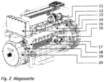
- Figure 2 shows the engine off Figure 1 from its exhaust side, approximately at the level of the cylinder head cover 23 or the cylinder head 2, the exhaust line and the exhaust gas turbocharger (ATL) 11 are arranged.
- the electric motor 12 is arranged on one end of the internal combustion engine by means of an SAE adapter unit 13.
- the EGR module 14 is arranged below the exhaust line and the exhaust gas turbocharger (ATL) 11 and above the electric motor/starter 16 and engine oil cooler 17, approximately at the level of the cylinder head 2.
- the high-voltage converter 15 is arranged on the other end of the internal combustion engine above the adapter unit 19 and the electric motor 20 and is connected to the electric motor 20 by means of a cable.
- a front plate 18 is arranged on the other end of the crankcase.
- Figure 3 the engine is switched off Figure 1 and Figure 2 divided into three areas A, B, and C, with area A representing one end face and area C representing the other end face of the engine or internal combustion engine.
- Area B essentially comprises the service side area of the internal combustion engine around the electric motor 8.
- the opened cylinder head sits on the crankcase 4 and reveals the wiring harness 22, which is located beneath the cylinder head cover 23.
- Injectors 25 protrude into the cylinder head beneath the cylinder head cover 23 to supply the internal combustion engine with fuel.
- the injectors are supplied with fuel by the common rail 21.
Landscapes
- Engineering & Computer Science (AREA)
- Chemical & Material Sciences (AREA)
- Combustion & Propulsion (AREA)
- Mechanical Engineering (AREA)
- General Engineering & Computer Science (AREA)
- Transportation (AREA)
- Cylinder Crankcases Of Internal Combustion Engines (AREA)
- Control Of Vehicle Engines Or Engines For Specific Uses (AREA)
- Hybrid Electric Vehicles (AREA)
- Exhaust-Gas Circulating Devices (AREA)
- Fuel-Injection Apparatus (AREA)
- Lubrication Of Internal Combustion Engines (AREA)
Description
- Die Erfindung betrifft eine Brennkraftmaschine mit wenigstens einem Elektromotor gemäß dem Oberbegriff des Anspruchs 1.
- Eine solche Brennkraftmaschine ist aus der
DE 10 2013 020 440 A1 bekannt. - Bei bisherigen Hybridkonzepten sind die Komponenten (elektrische E-Maschinen) meist für die getriebeseitige Aufnahme konzipiert. Die Motorarchitektur der heutigen Verbrennungsmotoren ist weitestgehend durch die klassische Anordnung der Systemkomponenten bestimmt, deren bestehende Schnittstellen für zukünftige Technologien wie z. B nahtlose Hybridisierung konzeptionell nicht umfassend vorbereitet sind. Diese Tatsache stellt jegliche nachträgliche Hybrid-Applikation vor eine große technische und wirtschaftliche Herausforderung.
- Das heißt, mit steigenden Kundenanforderungen und Applikationen in Bezug auf die Vielfalt der Hybridsysteme wird es immer schwieriger, mit einem traditionellen Konzept des Basismotors diese Aufgaben mit vertretbarem Aufwand zu bewältigen.
- Die Aufgabe der vorliegenden Erfindung ist es, diese Komponenten in den Verbrennungsmotor derart zu integrieren, um die Vielzahl möglicher Kundenapplikationen mit oder ohne spezieller Getriebevarianten abdecken zu können und das Kundenspektrum für die Zukunft zu erweitern.
- Die Aufgabe wird durch eine Brennkraftmaschine mit den Merkmalen des Anspruchs 1 gelöst. Beispielhafte Ausführungsformen ergeben sich aus den abhängigen Ansprüchen.
- Eine weitere vorteilhafte Ausgestaltung sieht vor, dass einer des wenigstens einen Elektromotors als Generator ausgebildet ist. Hierbei ist von Vorteil, dass überflüssig erzeugte Energie z. B. in Batterien gespeichert werden kann.
- Eine andere vorteilhafte Ausgestaltung sieht vor, dass ein Common-Rail in einem Zylinderkopfdeckel der Brennkraftmaschine angeordnet ist. Dies hat Bauraum- und Montagevorteile.
- Eine vorteilhafte Ausgestaltung sieht vor, dass ein Kabelbaum im Zylinderkopfdeckel angeordnet ist. Dies hat ebenfalls Bauraum- und Montagevorteile.
- Eine weitere vorteilhafte Ausgestaltung sieht vor, dass das Steuergerät auf oder am Zylinderkopfdeckel angeordnet ist. Dies hat ebenfalls Bauraum- und Montagevorteile.
- Eine andere vorteilhafte Ausgestaltung sieht vor, dass das Steuergerät leitungslos mit dem im Zylinderkopfdeckel integrierten Kabelbaum verbindbar ist. Dies hat ebenfalls Bauraum- und Montage- und Servicevorteile.
- Eine vorteilhafte Ausgestaltung sieht vor, dass ein Motorölkühler seitlich am Kurbelgehäuse in etwa in der Höhe und räumlich hinter einem des wenigstens einen Elektromotors angeordnet ist, insbesondere auf einer Abgasseite der Brennkraftmaschine. Dies hat Bauraum- und Montage- und Servicevorteile.
- Eine weitere vorteilhafte Ausgestaltung sieht vor, dass ein Abgasrückführ (AGR)-Modul seitlich am Kurbelgehäuse oberhalb des Motorölkühlers angeordnet ist, insbesondere auf der Abgasseite der Brennkraftmaschine. Dies hat Bauraum- und Montage- und Servicevorteile.
- Eine andere vorteilhafte Ausgestaltung sieht vor, dass eine Hochdruckpumpe seitlich am Zylinderkopf, insbesondere auf einer Serviceseite der Brennkraftmaschine derart angeordnet ist, dass sie leitungslos mit einem im Zylinderkopfdeckel angeordneten Common-Rail verbindbar ist. Dies hat Bauraum- und Montage- und Servicevorteile.
- Eine andere vorteilhafte Ausgestaltung sieht vor, dass wenigstens eine Hydraulikpumpe unterhalb des seitlich am Kurbelgehäuse angeordneten Elektromotors angeordnet ist und, wie der Elektromotor, über ein Getriebe an den stirnseitigen Rädertrieb angeordnet ist. Dies hat Bauraum- und Montage- und Servicevorteile und erhöht die Applikationsmöglichkeiten.
- Weitere Vorteile der Erfindung sind ein verstärktes Kurbelgehäuse mit definierter Kraftanbindung. Die Funktion des vorderen Deckels wird im Kurbelgehäuse integriert. Verstärktes Triebwerk und Rädertrieb mit spezieller Lagerung (die Kurbelwelle weist zum Schwungrad und zum Rand jeweils größeres Lager); Design des Motors für die Blockbauweise als tragende Einheit für die Anbindung vorwärts, rückwärts und seitwärts konzipiert;
(zusammen mit einer Gussölwanne wird der Motor zum tragenden Bauteil); - Anbindungsmöglichkeiten diverser Hybridsysteme für Industriebereich gegeben; das Design mit Verbrennungsmotoren unterschiedlicher Zylinder-Anzahl, z. B. 4 und 6 kompatibel (die Außengeometrie des Drehschwingungsdämpfers weist Funktionstrennung auf); Anpassung im Kühlmittel- und Ölkreislauf, optimiert hinsichtlich Druckverlust; multifunktionales Vorsatzgetriebe für High Speed E-Maschine und PTO mit Kupplung und leitungsloser Ölversorgung über Steckverbindungen; riemenloser Motor mit durchgehend elektrifizierten Nebenaggregaten als Option; konsequente Funktionstrennung und Verteilung der Systemkomponenten nach strengen Sicherheitskriterien und Service-Anforderungen für den bestmöglichen Kundennutzen.
- In einer bevorzugten Ausgestaltung ist vorgesehen, dass die Hochdruckpumpe von einem Schall-, Tritt- bzw. Schlagschutzkäfig umgeben ist.
- Die Erfindung wird im Folgenden anhand eines Ausführungsbeispiels näher erläutert, es zeigen:
- Figur 1
- die Serviceseite der Brennkraftmaschine
- Figur 2
- die Abgasseite der Brennkraftmaschine
- Figur 3
- die einzelnen Bauraumbereiche.
- Figur 4
- eine Draufsicht in den Zylinderkopf
- Die grundsätzliche Idee besteht darin, das gesamte System hinsichtlich Baugruppenanordnung und Auslegung der Komponenten so zu modifizieren, dass die Komplexität des Grundmotors im Design einerseits abnimmt und gleichzeitig, durch gewonnene Freiheitsgrade und neue verstärkte Schnittstellen, zwecks einfacherer Integration ausgenutzt werden kann. Damit können generell drei Bauraumbereiche für die Aufnahme der jeweiligen Hybridsysteme dargestellt werden (Bsp. siehe
Figur 3 ): - (A) Bereich Schwungrad & SAE
- (B) Bereich Serviceseite & PTO
- (C) Bereich Lüfter & Riementrieb
- Die Erfindung betrifft die gesamte aufeinander abgestimmte und ineinandergreifende Anordnung der Systemkomponenten. Bei dieser vorteilhaften Ausführungsform, mit klarer Funktionstrennung, werden alle Schlüssel- Baugruppen so segmentiert und neu kombiniert, dass dabei eine sehr hohe Funktionsdichte bei der optimalen und kompakten Bauraumausnutzung erreicht werden kann. In
Figur 1 undFigur 2 wird ein obenliegendes Steuer- gerät 1 gezeigt, mit einem direkten Kabelkanal, der entweder parallel zum Zylinderkopfdeckel oder innerhalb des Zylinderkopfdeckels angeordnet ist. Es gibt die Kabelkanal-Variante mit oder ohne Staub- bzw. Wasserschutz. Der Zylinderkopf 2 ist im Cross Flow Design konzipiert und beinhaltet Common-Rail-Injektoren 25 mit Hochdruckleitungen und staubgeschützter Ummantelung diverser Komponenten des Einspritzsystems. Des Weiteren verfügt der Zylinderkopf 2 über Sensoren, Schnittstellen und Anbindungs- punkte für die Abgasnachbehandlung (EAT-System). Die Kunden-Verrohrungs-Anbindung(KVA) weist optional obenliegende Lüfter-Lagerung, Motortrittschutz und Motortransport-Halterung sowie eine obenliegende Hochdruckpumpe 3 auf, die direkt am Zylinderkopf mit oder ohne Akustikschutz angebunden ist bzw. sind. Das Kurbelgehäuse 4 ist mit oder ohne Funktion der Aufteilung des Kühlmittelkreislaufes, dem sogenannten Split Cooling ausgeführt. Die geschlossene Ölwannenkontur ohne Unterbrechung der Dichtung führt zu einem verstärkten Triebwerk und einem verstärkten Rädertrieb. Die AGR-Rückführung ist auf der Abgasseite der Brennkraftmaschine angeordnet. Es existieren Schnittstellen für die Anbaukomponenten und die Motorlagerung. Das Filter Modul 5 für Kraftstoff und Öl ist losgelöst von der Funktion der Öl-Kühlung. Das Power Take Off (PTO) Modul (B) 6 ist direkt am Kurbelgehäuse 4 angebaut. Das Vorsatzgetriebe 7, ist beispielsweise ein Stirnradgetriebe für eine schnellere Übersetzung - mit oder ohne elastischer Kupplung. Die Brennkraftmaschine weist eine staubgeschützte Aufnahme der E-Maschine (System High Speed) auf. Weiter weist die Brennkraftmaschine eine direkte leitungslose Ölversorgung über Steckelemente auf. Die E-Maschine 8 (System High Speed) ist für den Heavy Duty Bereich; staubgeschützt ausgeführt. Die Abstützkonsole 9 mit Toleranzausgleich ist direkt am Kurbelgehäuse angebunden. Die Ölwanne 10 ist im Akustikverhalten optimiert und als Blech, Guss oder Kunststoff teil ausgeführt. Die Abgasleitung und der ATL 11 kann in diversen Anbaupositionen realisiert werden. Das AGR-Modul-System 14 kann mit oder ohne integrierter Stelleinheit realisiert und im Kurbelgehäuse voll integriert sein, es ist direkt und strömungsgünstig mit dem Kühlkreislaufsystem verbunden, ohne Haltekonsole und ohne Kühlmittelleitungen, mit der Abgasrückführung im Kurbelgehäuse, die je nach Abgasstufe im Funktionsumfang skalierbar ist. Die E-Maschine 12 (System Mild Hybrid) in der Ausführung für den Heavy Duty Bereich ist staubgeschützt. Die Adaptereinheit 13 (SAE-Bereich) für die direkte Anbindung der E-Maschine ist zentriert am Kurbelgehäuse angeordnet. Der HochvoltUmrichter 15 ist an der Frontplatte weichgelagert angebunden. Der Anlasser 16 kann mit oder ohne Staubschutz bzw. mit oder ohne Wasserschutz ausgeführt sein. Der Motorölkühler 17 ist voll im Kurbelgehäuse integriert und direkt und strömungsgünstig mit dem Kühlkreislaufsystem verbunden. Die Frontplatte 18 ist direkt verbunden und am Kurbelgehäuse zentriert angeordnet. Die Adaptereinheit 19 ist im Bereich Lüfter & Riementrieb für die direkte Anbindung der E-Maschine 20 zentriert am Kurbelgehäuse angeordnet. In der Ausführung für den Heavy Duty Bereich ist die E-Maschine 20 und die Adaptereinheit 19 staubgeschützt angeordnet. -
Figur 1 stellt das Steuergerät 1 auf dem Zylinderkopfdeckel 23 dar, der mit dem parallel zum Zylinderkopfdeckel 23 angeordneten Kabelbaumkanal 22 verbunden ist. Am Zylinderkopf 2 ist die Dieselhochdruckpumpe 3 im Wesentlichen leitungslos mit dem nicht sichtbaren und inFigur 4 gezeigten dargestellten Common-Rail 21 verbunden. Das Filtermodul 5 ist am Kurbelgehäuse 4 auf der Service-Seite angeordnet. Auf der Service-Seite unterhalb der Dieselhochdruckpumpe 3 ist der sogenannte Power Take Off (PTO) 6 oberhalb von Vorsatzgetriebe 7 angeordnet. Am Vorsatzgetriebe 7 ist der Elektromotor 8 angeordnet, wobei das Vorsatzgetriebe 7 am stirnseitigen Rädertrieb angeordnet ist. Die Abstützkonsole 9 stützt den Elektromotor 8 und grenzt an die Hydraulikpumpe 24. Unterhalb des Kurbelgehäuses 4 ist die Ölwanne 10 angeordnet. -
Figur 2 zeigt den Motor ausFigur 1 von seiner Abgasseite, in etwa in Höhe des Zylinderkopfdeckels 23 bzw. des Zylinderkopfes 2 ist die Abgasleitung und der Abgasturbolader (ATL) 11 angeordnet. Der Elektromotor 12 ist mittels einer SAE-Adaptereinheit 13 an einer Stirnseite der Brennkraftmaschine angeordnet. Das AGR-Modul 14 ist unterhalb der Abgasleitung und des Abgasturboladers (ATL) 11 und oberhalb von Elektromotor/Anlasser 16 und Motorölkühler 17 in etwa in Höhe des Zylinderkopfs 2 angeordnet. Der Hochvoltumrichter 15 ist an der anderen Stirnseite der Brennkraftmaschine oberhalb von Adaptereinheit 19 und Elektromotor 20 angeordnet und leitungsmäßig mit dem Elektromotor 20 verbunden. An der anderen Stirnseite des Kurbelgehäuses ist eine Frontplatte 18 angeordnet. - In
Figur 3 wird der Motor ausFigur 1 undFigur 2 in drei Bereiche A, B und C aufgeteilt dargestellt, wobei Bereich A die eine Stirnseite darstellt und Bereich C die andere Stirnseite des Motors bzw. der Brennkraftmaschine. Der Bereich B umfasst im Wesentlichen den Service-Seitenbereich der Brennkraftmaschine um den Elektromotor 8. - In
Figur 4 wird die Anordnung der Dieselhochdruckpumpe 3 dargestellt, die im Wesentlichen leitungslos mit dem Common-Rail 21 verbunden ist. - Der geöffnete Zylinderkopf sitzt auf dem Kurbelgehäuse 4 und zeigt den Kabelbaum 22, der unter dem Zylinderkopfdeckel 23 angeordnet ist. Unter dem Zylinderkopfdeckel 23 ragen Injektoren 25 in den Zylinderkopf zur Versorgung der Brennkraftmaschine mit Kraftstoff hinein, wobei die Injektoren vom Common-Rail 21 mit Kraftstoff versorgt werden.
-
- 1 Steuergerät
- 2 Zylinderkopf
- 3 Dieselhochdruckpumpe
- 4 Kurbelgehäuse
- 5 Filtermodul
- 6 Power Take Off(PTO)
- 7 Vorsatzgetriebe
- 8 Elektromotor
- 9 Abstützkonsole
- 10 Ölwanne
- 11 Abgasleitung und Abgasturbolader (ATL)
- 12 Elektromotor
- 13 SAE-Adaptereinheit
- 14 AGR-Modul
- 15 Hochvoltumrichter
- 16 Elektromotor/Anlasser
- 17 Motorölkühler
- 18 Frontplatte
- 19 Adaptereinheit
- 20 Elektromotor
- 21 Common-Rail
- 22 Kabelbaum
- 23 Zylinderkopfdeckel
- 24 Hydraulikpumpe
- 25 Injektor
Claims (11)
- Brennkraftmaschine, umfassendwenigstens einen am Kurbelgehäuse der Brennkraftmaschine angeordneten Elektromotor (8, 13, 16, 20),wenigstens ein Steuergerät (1) zur Steuerung von Brennkraftmaschine und/oder Elektromotor,wenigstens einen Hochvoltumrichter (15), der an einer Stirnseite der Brennkraftmaschine oberhalb von einer Adaptereinheit (19) und einem des zumindest einen Elektromotors (20) angeordnet und leitungsmäßig mit dem Elektromotor (20) verbunden ist, wobei die Adaptereinheit (19) in einem Bereich eines Lüfter- und Riementriebs für die direkte Anbindung des Elektromotors (20) zentriert am Kurbelgehäuse angeordnet ist, und wenigstens ein direkt am Kurbelgehäuse (4) angebautes Power Take Off (PTO) Modul (6), das antriebsmäßig mit einem Vorsatzgetriebe (7) verbunden ist, das an einem stirnseitigen Rädertrieb angeordnet ist, wobei ein weiterer des wenigstens einen Elektromotors (8) mit dem Vorsatzgetriebe (7) antriebsverbunden ist.
- Brennkraftmaschine nach Anspruch 1,
dadurch gekennzeichnet, dass einer des wenigstens einen Elektromotors als Anlasser (8, 13, 16, 20) ausgebildet ist. - Brennkraftmaschine nach einem oder mehreren der vorgenannten Ansprüche,
dadurch gekennzeichnet, dass einer des wenigstens einen Elektromotors (8, 13, 16, 20) als Generator ausgebildet ist. - Brennkraftmaschine nach einem oder mehreren der vorgenannten Ansprüche,
dadurch gekennzeichnet, dass die Brennkraftmaschine ferner einen Common-Rail und einen Zylinderkopfdeckel umfasst, wobei der Common-Rail im Zylinderkopfdeckel angeordnet ist. - Brennkraftmaschine nach Anspruch 4,
dadurch gekennzeichnet, dass ein Kabelbaum im Zylinderkopfdeckel angeordnet ist. - Brennkraftmaschine nach Anspruch 5,
dadurch gekennzeichnet, dass das Steuergerät (1) auf oder am Zylinderkopfdeckel angeordnet ist. - Brennkraftmaschine nach Anspruch 5 oder 6,
dadurch gekennzeichnet, dass das Steuergerät (1) leitungslos mit dem im Zylinderkopfdeckel integrierten Kabelbaum verbindbar ist. - Brennkraftmaschine nach einem oder mehreren der vorgenannten Ansprüche,
dadurch gekennzeichnet, dass ein Motorölkühler (17) seitlich am Kurbelgehäuse in etwa der Höhe und räumlich hinter einem des wenigstens einen Elektromotors (16) angeordnet ist, insbesondere auf einer Abgasseite der Brennkraftmaschine. - Brennkraftmaschine nach Anspruch 8,
dadurch gekennzeichnet, dass ein Abgasrückführ(AGR)-Modul seitlich am Kurbelgehäuse oberhalb des Motorölkühlers (17) angeordnet ist, insbesondere auf einer Abgasseite der Brennkraftmaschine. - Brennkraftmaschine nach einem oder mehreren der vorgenannten Ansprüche,
dadurch gekennzeichnet, dass eine Hochdruckpumpe seitlich an einem Zylinderkopf der Brennkraftmaschine, insbesondere auf einer Serviceseite der Brennkraftmaschine derart angeordnet ist, dass sie leitungslos mit einem im Zylinderkopfdeckel angeordneten Common-Rail verbindbar ist. - Brennkraftmaschine nach einem oder mehreren der vorgenannten Ansprüche,
dadurch gekennzeichnet, dass wenigstens eine Hydraulikpumpe unterhalb des seitlich am Kurbelgehäuse angeordneten Elektromotors (8) angeordnet ist und wie der Elektromotor (8) über ein Getriebe an den stirnseitigen Rädertrieb angeordnet ist.
Applications Claiming Priority (2)
| Application Number | Priority Date | Filing Date | Title |
|---|---|---|---|
| DE102015006365.0A DE102015006365B4 (de) | 2015-05-20 | 2015-05-20 | Brennkraftmaschine mit mindestens einem Elektromotor |
| PCT/EP2016/000732 WO2016184545A1 (de) | 2015-05-20 | 2016-05-04 | Brennkraftmaschine mit mindestens einem elektromotor |
Publications (2)
| Publication Number | Publication Date |
|---|---|
| EP3298267A1 EP3298267A1 (de) | 2018-03-28 |
| EP3298267B1 true EP3298267B1 (de) | 2025-04-23 |
Family
ID=56363803
Family Applications (1)
| Application Number | Title | Priority Date | Filing Date |
|---|---|---|---|
| EP16735816.7A Active EP3298267B1 (de) | 2015-05-20 | 2016-05-04 | Brennkraftmaschine mit einem elektromotor |
Country Status (6)
| Country | Link |
|---|---|
| US (1) | US11028811B2 (de) |
| EP (1) | EP3298267B1 (de) |
| JP (1) | JP7117848B2 (de) |
| CN (1) | CN107889515A (de) |
| DE (1) | DE102015006365B4 (de) |
| WO (1) | WO2016184545A1 (de) |
Families Citing this family (1)
| Publication number | Priority date | Publication date | Assignee | Title |
|---|---|---|---|---|
| US12012913B2 (en) * | 2021-11-10 | 2024-06-18 | Cummins Inc. | Fuel system cover for an internal combustion engine |
Citations (2)
| Publication number | Priority date | Publication date | Assignee | Title |
|---|---|---|---|---|
| DE19953864A1 (de) * | 1998-11-11 | 2000-05-31 | Nissan Motor | Hochleistungskabel-Ausrichtvorrichtung für ein Elektrofahrzeug |
| WO2016134835A1 (de) * | 2015-02-23 | 2016-09-01 | Deutz Aktiengesellschaft | Hybridantriebsstrang |
Family Cites Families (54)
| Publication number | Priority date | Publication date | Assignee | Title |
|---|---|---|---|---|
| US5163335A (en) * | 1991-07-15 | 1992-11-17 | Patrick D. Isom | Universal starter motor assembly |
| DE9410232U1 (de) * | 1994-06-27 | 1995-11-02 | Robert Bosch Gmbh, 70469 Stuttgart | Kraftstoffeinspritzeinrichtung für Brennkraftmaschinen |
| JPH09317556A (ja) * | 1996-05-23 | 1997-12-09 | Toyota Motor Corp | シリンダヘッドカバー |
| JP3661288B2 (ja) * | 1996-08-05 | 2005-06-15 | 株式会社エクォス・リサーチ | ハイブリッド型車両 |
| DE19750298A1 (de) | 1997-11-13 | 1999-05-20 | Man Nutzfahrzeuge Ag | Brennkraftmaschine mit Hochdruckeinspritzsystem |
| US20020139344A1 (en) | 2001-04-02 | 2002-10-03 | Yazaki Corporation | Built-in engine type control apparatus |
| JP2002364506A (ja) | 2001-04-02 | 2002-12-18 | Yazaki Corp | エンジン一体型制御装置 |
| JP3983006B2 (ja) | 2001-04-13 | 2007-09-26 | 富士重工業株式会社 | エンジン発電機 |
| JP2004060570A (ja) * | 2002-07-30 | 2004-02-26 | Yamaha Motor Co Ltd | エンジン発電機 |
| JP4065174B2 (ja) * | 2002-10-01 | 2008-03-19 | 本田技研工業株式会社 | ハイブリッド車両 |
| DE10303102A1 (de) | 2003-01-28 | 2004-07-29 | Deutz Ag | Kühlwasserpumpenmodul |
| JP2004360520A (ja) * | 2003-06-03 | 2004-12-24 | Suzuki Motor Corp | ベルト式無段変速機構を備えた4ストロークエンジン |
| DE10336599B4 (de) * | 2003-08-08 | 2016-08-04 | Daimler Ag | Verfahren zur Ansteuerung eines Thermostaten in einem Kühlkreislauf eines Verbrennungsmotors |
| DE10338649B4 (de) * | 2003-08-22 | 2005-08-11 | Audi Ag | Kraftfahrzeug |
| JP4074860B2 (ja) * | 2004-03-19 | 2008-04-16 | 株式会社クボタ | 縦型多気筒ディーゼルエンジン |
| US7089890B2 (en) * | 2004-07-12 | 2006-08-15 | International Engine Intellectual Property Company, Llc | Cooling system for an internal combustion engine with exhaust gas recirculation (EGR) |
| US7419021B2 (en) * | 2004-09-27 | 2008-09-02 | Oshkosh Truck Corporation | Engine and generator orientation within a hybrid vehicle |
| DE102005031300B4 (de) | 2005-07-05 | 2021-05-12 | Daimler Ag | Brennkraftmaschine mit Kühlsystem und Abgasrückführsystem |
| DE102005036087A1 (de) * | 2005-08-01 | 2007-02-08 | Ktm-Sportmotorcycle Ag | Elektrische Startvorrichtung einer Brennkraftmaschine |
| JP2008116018A (ja) | 2006-11-08 | 2008-05-22 | Toyota Motor Corp | 動力伝達装置 |
| US7409949B1 (en) * | 2007-01-22 | 2008-08-12 | Brp-Rotax Gmbh & Co. Kg | Ignition housing for internal combustion engine |
| DE102007009955B4 (de) * | 2007-03-01 | 2009-10-15 | Mtu Friedrichshafen Gmbh | Kurbelgehäuse |
| JP4914776B2 (ja) * | 2007-06-22 | 2012-04-11 | 本田技研工業株式会社 | 自動二輪車用パワーユニット |
| DE102007053493A1 (de) | 2007-11-09 | 2009-05-14 | Deutz Ag | Wasserpumpenträger zum Anbau an einer Brennkraftmaschine |
| JP4629724B2 (ja) * | 2007-12-20 | 2011-02-09 | 三菱自動車工業株式会社 | インジェクタの取付け構造 |
| US20100283242A1 (en) * | 2007-12-26 | 2010-11-11 | Dooley Kevin A | High Voltage Start of an Engine from a Low Voltage Battery |
| US7625257B1 (en) * | 2008-03-24 | 2009-12-01 | Brunswick Corporation | Exhaust gas recirculation cooling system for an engine of an outboard motor |
| JP2009236005A (ja) * | 2008-03-27 | 2009-10-15 | Yamaha Motor Co Ltd | 自動二輪車 |
| JP4569677B2 (ja) | 2008-07-08 | 2010-10-27 | トヨタ自動車株式会社 | ハイブリッド自動車 |
| CN101342860B (zh) * | 2008-08-21 | 2011-12-21 | 台州市黄岩华阳电动车有限公司 | 一种油电混合动力装置 |
| JP5091062B2 (ja) * | 2008-09-02 | 2012-12-05 | 本田技研工業株式会社 | 車両用エンジン |
| GB2464622B (en) * | 2008-09-18 | 2010-10-20 | Controlled Power Technologies | A power terminal in an intergrated starter generator |
| WO2011072836A1 (de) * | 2009-12-17 | 2011-06-23 | Deutz Aktiengesellschaft | Mobile arbeitsmaschine mit integriertem starter generator |
| FR2955715B1 (fr) * | 2010-01-28 | 2015-08-07 | Peugeot Citroen Automobiles Sa | Procede pour optimiser la recharge de la batterie d'un vehicule hybride |
| JP2011163252A (ja) * | 2010-02-12 | 2011-08-25 | Honda Motor Co Ltd | エンジン |
| US8826891B2 (en) * | 2010-12-02 | 2014-09-09 | Toyota Jidosha Kabushiki Kaisha | Control apparatus for internal combustion engine |
| US8844493B2 (en) * | 2010-12-28 | 2014-09-30 | Kawasaki Jukogyo Kabushiki Kaisha | Lubricating oil feeding structure of engine |
| JP5270702B2 (ja) | 2011-02-14 | 2013-08-21 | トヨタ自動車株式会社 | 車両用機器搭載構造 |
| DE102011012095B4 (de) * | 2011-02-23 | 2015-07-02 | Hrvoje Salinovic | AMICES II : Hybridisierung der Brennkraftmotorsysteme nach dem Additionsprinzip |
| DE102011100188B3 (de) * | 2011-05-02 | 2012-06-21 | Mtu Friedrichshafen Gmbh | Master-Slaveanordnung eines elektronischen Motorsteuergeräts mit einem Motoridentifikationsmodul |
| KR101219879B1 (ko) * | 2011-07-04 | 2013-01-09 | 기아자동차주식회사 | 벨트구동 스타트 시스템 |
| JP5758224B2 (ja) * | 2011-08-09 | 2015-08-05 | 本田技研工業株式会社 | 車両用パワーユニットの油圧クラッチ制御装置 |
| JP5603310B2 (ja) * | 2011-10-21 | 2014-10-08 | 本田技研工業株式会社 | エンジン作業機の位置規制装置 |
| AU2013221384B2 (en) * | 2012-02-17 | 2015-07-02 | Allison Transmission, Inc. | High voltage cable detection using rotating machine in hybrid vehicles |
| JP2014065465A (ja) * | 2012-09-27 | 2014-04-17 | Honda Motor Co Ltd | 自動二輪車用内燃機関 |
| US9709001B2 (en) * | 2012-09-28 | 2017-07-18 | Global Ip Development Foundation | Internal combustion engine with hinged access to lower block |
| JP5928354B2 (ja) * | 2013-01-23 | 2016-06-01 | マツダ株式会社 | 火花点火式多気筒エンジンの始動装置 |
| US9522674B2 (en) * | 2013-03-26 | 2016-12-20 | Honda Motor Co., Ltd. | Internal combustion engine control device and internal combustion engine control method |
| JP2014227921A (ja) * | 2013-05-23 | 2014-12-08 | ヤマハ発動機株式会社 | 内燃機関の冷却装置およびそれを備えた自動二輪車 |
| US9080542B2 (en) * | 2013-06-19 | 2015-07-14 | Ford Global Technologies, Llc | Engine cranking torque referenced to an engine stop position |
| JP2015074384A (ja) * | 2013-10-10 | 2015-04-20 | ヤマハ発動機株式会社 | 鞍乗型車両 |
| DE102013020440A1 (de) * | 2013-12-06 | 2014-07-24 | Daimler Ag | Verbindungselement zwischen integriertem Starter-Generator und Leistungselektronik |
| US20160290304A1 (en) * | 2014-03-13 | 2016-10-06 | Panasonic Intellectual Property Management Co., Ltd. | Engine starting device |
| EP3015677B1 (de) * | 2014-10-28 | 2018-04-04 | Toyota Jidosha Kabushiki Kaisha | Steuerungsvorrichtung für einen verbrennungsmotor |
-
2015
- 2015-05-20 DE DE102015006365.0A patent/DE102015006365B4/de active Active
-
2016
- 2016-05-04 JP JP2017553878A patent/JP7117848B2/ja active Active
- 2016-05-04 WO PCT/EP2016/000732 patent/WO2016184545A1/de not_active Ceased
- 2016-05-04 CN CN201680029076.4A patent/CN107889515A/zh active Pending
- 2016-05-04 US US15/571,968 patent/US11028811B2/en active Active
- 2016-05-04 EP EP16735816.7A patent/EP3298267B1/de active Active
Patent Citations (2)
| Publication number | Priority date | Publication date | Assignee | Title |
|---|---|---|---|---|
| DE19953864A1 (de) * | 1998-11-11 | 2000-05-31 | Nissan Motor | Hochleistungskabel-Ausrichtvorrichtung für ein Elektrofahrzeug |
| WO2016134835A1 (de) * | 2015-02-23 | 2016-09-01 | Deutz Aktiengesellschaft | Hybridantriebsstrang |
Also Published As
| Publication number | Publication date |
|---|---|
| JP7117848B2 (ja) | 2022-08-15 |
| DE102015006365A1 (de) | 2016-11-24 |
| CN107889515A (zh) | 2018-04-06 |
| US11028811B2 (en) | 2021-06-08 |
| US20180128230A1 (en) | 2018-05-10 |
| JP2018521253A (ja) | 2018-08-02 |
| EP3298267A1 (de) | 2018-03-28 |
| DE102015006365B4 (de) | 2021-09-30 |
| WO2016184545A1 (de) | 2016-11-24 |
Similar Documents
| Publication | Publication Date | Title |
|---|---|---|
| DE102011105041B4 (de) | Schmiervorrichtung für einen Turbolader eines Motors für ein Fahrzeug | |
| DE102007053126B4 (de) | Brennkraftmaschine mit gekühlter Abgasrückführung sowie Abgaskrümmer | |
| DE102011104450A1 (de) | Turboladevorrichtung für einen Fahrzeugmotor | |
| AT512567B1 (de) | Funktionsmodul mit einem Abgasturbolader und einem Abgaskrümmer | |
| EP2769067B1 (de) | Ansaugmodul für eine verbrennungskraftmaschine | |
| DE102018217818B3 (de) | Antriebseinheit umfassend eine Brennkraftmaschine und eine Elektromaschine und Verfahren zum Betreiben einer derartigen Antriebseinheit | |
| DE102013200854A1 (de) | Wärmerückgewinnungssystem für ein fahrzeug | |
| DE102011116310A1 (de) | Anordnung einer Luftversorgungseinrichtung an einem Zylinderkopf für eine Verbrennungskraftmaschine | |
| DE102012017391A1 (de) | Saugrohr für einen Verbrennungsmotor | |
| DE102017000710A1 (de) | Einlassluftkühlvorrichtung für einen Motor | |
| EP2256314A1 (de) | Verbrennungsmotor | |
| DE202006020495U1 (de) | Modularer Antrieb für Schienenfahrzeuge mit Verbrennungsmotorantrieb | |
| DE19818700A1 (de) | Brennkraftmaschine mit einem integrierten Front-End | |
| DE102007017854A1 (de) | Brennkraftmaschine | |
| DE102010036303B4 (de) | Verbrennungsmotor mit liegend angeordneten Zylinderbänken und Abgasturbolader | |
| EP3298267A1 (de) | Brennkraftmaschine mit mindestens einem elektromotor | |
| EP2077386B1 (de) | Zylinderkopf mit im Zylinderkopf integriertem Abgaskrümmer | |
| EP3061641B1 (de) | Verfahren und vorrichtung zur ansteuerung eines antriebssystems eines kraftfahrzeugs mit einem nebenabtrieb | |
| DE102017200948A1 (de) | Verfahren zum Betrieb einer turboaufgeladenen Brennkraftmaschine | |
| DE102020200735A1 (de) | Tragstruktur für ein nebenaggregat innerhalb eines verbrennungsmotors für ein fahrzeug | |
| EP3951147A1 (de) | Nebentrieb einer brennkraftmaschine | |
| DE102019207912B4 (de) | Motoranordnung mit stirnseitig angeordnetem Lader | |
| DE102016101702B4 (de) | Antriebssystem eines Fahrzeuges | |
| DE19729550A1 (de) | Antriebseinrichtung für Fahrzeuge und Verfahren zum Betreiben einer Antriebseinrichtung | |
| DE102013113228A1 (de) | Einrichtung zur Versorgung von Betriebskomponenten eines Kraftfahrzeugs mit Luft |
Legal Events
| Date | Code | Title | Description |
|---|---|---|---|
| STAA | Information on the status of an ep patent application or granted ep patent |
Free format text: STATUS: THE INTERNATIONAL PUBLICATION HAS BEEN MADE |
|
| PUAI | Public reference made under article 153(3) epc to a published international application that has entered the european phase |
Free format text: ORIGINAL CODE: 0009012 |
|
| STAA | Information on the status of an ep patent application or granted ep patent |
Free format text: STATUS: REQUEST FOR EXAMINATION WAS MADE |
|
| 17P | Request for examination filed |
Effective date: 20171011 |
|
| AK | Designated contracting states |
Kind code of ref document: A1 Designated state(s): AL AT BE BG CH CY CZ DE DK EE ES FI FR GB GR HR HU IE IS IT LI LT LU LV MC MK MT NL NO PL PT RO RS SE SI SK SM TR |
|
| AX | Request for extension of the european patent |
Extension state: BA ME |
|
| RIN1 | Information on inventor provided before grant (corrected) |
Inventor name: FEUSER, WILHELM Inventor name: SCHWABAUER, PAUL Inventor name: KLEINSCHMIDT, ANTON Inventor name: HOFFMANN, PETER Inventor name: JOISTEN-PIERITZ, JOACHIM Inventor name: KNAPS, GERHARD Inventor name: JUNG- MARCO Inventor name: BRUN, MARCO |
|
| DAV | Request for validation of the european patent (deleted) | ||
| DAX | Request for extension of the european patent (deleted) | ||
| STAA | Information on the status of an ep patent application or granted ep patent |
Free format text: STATUS: EXAMINATION IS IN PROGRESS |
|
| 17Q | First examination report despatched |
Effective date: 20210622 |
|
| GRAP | Despatch of communication of intention to grant a patent |
Free format text: ORIGINAL CODE: EPIDOSNIGR1 |
|
| STAA | Information on the status of an ep patent application or granted ep patent |
Free format text: STATUS: GRANT OF PATENT IS INTENDED |
|
| INTG | Intention to grant announced |
Effective date: 20241205 |
|
| GRAS | Grant fee paid |
Free format text: ORIGINAL CODE: EPIDOSNIGR3 |
|
| GRAA | (expected) grant |
Free format text: ORIGINAL CODE: 0009210 |
|
| STAA | Information on the status of an ep patent application or granted ep patent |
Free format text: STATUS: THE PATENT HAS BEEN GRANTED |
|
| AK | Designated contracting states |
Kind code of ref document: B1 Designated state(s): AL AT BE BG CH CY CZ DE DK EE ES FI FR GB GR HR HU IE IS IT LI LT LU LV MC MK MT NL NO PL PT RO RS SE SI SK SM TR |
|
| REG | Reference to a national code |
Ref country code: GB Ref legal event code: FG4D Free format text: NOT ENGLISH |
|
| REG | Reference to a national code |
Ref country code: CH Ref legal event code: EP |
|
| REG | Reference to a national code |
Ref country code: DE Ref legal event code: R096 Ref document number: 502016016962 Country of ref document: DE |
|
| REG | Reference to a national code |
Ref country code: IE Ref legal event code: FG4D Free format text: LANGUAGE OF EP DOCUMENT: GERMAN |
|
| REG | Reference to a national code |
Ref country code: SE Ref legal event code: TRGR |
|
| PGFP | Annual fee paid to national office [announced via postgrant information from national office to epo] |
Ref country code: DE Payment date: 20250528 Year of fee payment: 10 |
|
| PGFP | Annual fee paid to national office [announced via postgrant information from national office to epo] |
Ref country code: FR Payment date: 20250625 Year of fee payment: 10 |
|
| PGFP | Annual fee paid to national office [announced via postgrant information from national office to epo] |
Ref country code: SE Payment date: 20250618 Year of fee payment: 10 |
|
| REG | Reference to a national code |
Ref country code: NL Ref legal event code: MP Effective date: 20250423 |
|
| PG25 | Lapsed in a contracting state [announced via postgrant information from national office to epo] |
Ref country code: NL Free format text: LAPSE BECAUSE OF FAILURE TO SUBMIT A TRANSLATION OF THE DESCRIPTION OR TO PAY THE FEE WITHIN THE PRESCRIBED TIME-LIMIT Effective date: 20250423 |
|
| PG25 | Lapsed in a contracting state [announced via postgrant information from national office to epo] |
Ref country code: PT Free format text: LAPSE BECAUSE OF FAILURE TO SUBMIT A TRANSLATION OF THE DESCRIPTION OR TO PAY THE FEE WITHIN THE PRESCRIBED TIME-LIMIT Effective date: 20250825 Ref country code: ES Free format text: LAPSE BECAUSE OF FAILURE TO SUBMIT A TRANSLATION OF THE DESCRIPTION OR TO PAY THE FEE WITHIN THE PRESCRIBED TIME-LIMIT Effective date: 20250423 Ref country code: FI Free format text: LAPSE BECAUSE OF FAILURE TO SUBMIT A TRANSLATION OF THE DESCRIPTION OR TO PAY THE FEE WITHIN THE PRESCRIBED TIME-LIMIT Effective date: 20250423 |
|
| REG | Reference to a national code |
Ref country code: LT Ref legal event code: MG9D |
|
| PG25 | Lapsed in a contracting state [announced via postgrant information from national office to epo] |
Ref country code: NO Free format text: LAPSE BECAUSE OF FAILURE TO SUBMIT A TRANSLATION OF THE DESCRIPTION OR TO PAY THE FEE WITHIN THE PRESCRIBED TIME-LIMIT Effective date: 20250723 Ref country code: GR Free format text: LAPSE BECAUSE OF FAILURE TO SUBMIT A TRANSLATION OF THE DESCRIPTION OR TO PAY THE FEE WITHIN THE PRESCRIBED TIME-LIMIT Effective date: 20250724 |
|
| PG25 | Lapsed in a contracting state [announced via postgrant information from national office to epo] |
Ref country code: PL Free format text: LAPSE BECAUSE OF FAILURE TO SUBMIT A TRANSLATION OF THE DESCRIPTION OR TO PAY THE FEE WITHIN THE PRESCRIBED TIME-LIMIT Effective date: 20250423 |
|
| PG25 | Lapsed in a contracting state [announced via postgrant information from national office to epo] |
Ref country code: BG Free format text: LAPSE BECAUSE OF FAILURE TO SUBMIT A TRANSLATION OF THE DESCRIPTION OR TO PAY THE FEE WITHIN THE PRESCRIBED TIME-LIMIT Effective date: 20250423 |
|
| PG25 | Lapsed in a contracting state [announced via postgrant information from national office to epo] |
Ref country code: HR Free format text: LAPSE BECAUSE OF FAILURE TO SUBMIT A TRANSLATION OF THE DESCRIPTION OR TO PAY THE FEE WITHIN THE PRESCRIBED TIME-LIMIT Effective date: 20250423 |
|
| PG25 | Lapsed in a contracting state [announced via postgrant information from national office to epo] |
Ref country code: RS Free format text: LAPSE BECAUSE OF FAILURE TO SUBMIT A TRANSLATION OF THE DESCRIPTION OR TO PAY THE FEE WITHIN THE PRESCRIBED TIME-LIMIT Effective date: 20250723 |
|
| PG25 | Lapsed in a contracting state [announced via postgrant information from national office to epo] |
Ref country code: IS Free format text: LAPSE BECAUSE OF FAILURE TO SUBMIT A TRANSLATION OF THE DESCRIPTION OR TO PAY THE FEE WITHIN THE PRESCRIBED TIME-LIMIT Effective date: 20250823 |
|
| PG25 | Lapsed in a contracting state [announced via postgrant information from national office to epo] |
Ref country code: LV Free format text: LAPSE BECAUSE OF FAILURE TO SUBMIT A TRANSLATION OF THE DESCRIPTION OR TO PAY THE FEE WITHIN THE PRESCRIBED TIME-LIMIT Effective date: 20250423 |
|
| REG | Reference to a national code |
Ref country code: CH Ref legal event code: H13 Free format text: ST27 STATUS EVENT CODE: U-0-0-H10-H13 (AS PROVIDED BY THE NATIONAL OFFICE) Effective date: 20251223 |
|
| PG25 | Lapsed in a contracting state [announced via postgrant information from national office to epo] |
Ref country code: SM Free format text: LAPSE BECAUSE OF FAILURE TO SUBMIT A TRANSLATION OF THE DESCRIPTION OR TO PAY THE FEE WITHIN THE PRESCRIBED TIME-LIMIT Effective date: 20250423 Ref country code: DK Free format text: LAPSE BECAUSE OF FAILURE TO SUBMIT A TRANSLATION OF THE DESCRIPTION OR TO PAY THE FEE WITHIN THE PRESCRIBED TIME-LIMIT Effective date: 20250423 |
|
| PG25 | Lapsed in a contracting state [announced via postgrant information from national office to epo] |
Ref country code: LU Free format text: LAPSE BECAUSE OF NON-PAYMENT OF DUE FEES Effective date: 20250504 |
|
| PG25 | Lapsed in a contracting state [announced via postgrant information from national office to epo] |
Ref country code: CH Free format text: LAPSE BECAUSE OF NON-PAYMENT OF DUE FEES Effective date: 20250531 |
|
| PG25 | Lapsed in a contracting state [announced via postgrant information from national office to epo] |
Ref country code: CZ Free format text: LAPSE BECAUSE OF FAILURE TO SUBMIT A TRANSLATION OF THE DESCRIPTION OR TO PAY THE FEE WITHIN THE PRESCRIBED TIME-LIMIT Effective date: 20250423 |
|
| PG25 | Lapsed in a contracting state [announced via postgrant information from national office to epo] |
Ref country code: EE Free format text: LAPSE BECAUSE OF FAILURE TO SUBMIT A TRANSLATION OF THE DESCRIPTION OR TO PAY THE FEE WITHIN THE PRESCRIBED TIME-LIMIT Effective date: 20250423 |
|
| REG | Reference to a national code |
Ref country code: DE Ref legal event code: R097 Ref document number: 502016016962 Country of ref document: DE |
|
| PG25 | Lapsed in a contracting state [announced via postgrant information from national office to epo] |
Ref country code: SK Free format text: LAPSE BECAUSE OF FAILURE TO SUBMIT A TRANSLATION OF THE DESCRIPTION OR TO PAY THE FEE WITHIN THE PRESCRIBED TIME-LIMIT Effective date: 20250423 Ref country code: RO Free format text: LAPSE BECAUSE OF FAILURE TO SUBMIT A TRANSLATION OF THE DESCRIPTION OR TO PAY THE FEE WITHIN THE PRESCRIBED TIME-LIMIT Effective date: 20250423 |
|
| PG25 | Lapsed in a contracting state [announced via postgrant information from national office to epo] |
Ref country code: IT Free format text: LAPSE BECAUSE OF FAILURE TO SUBMIT A TRANSLATION OF THE DESCRIPTION OR TO PAY THE FEE WITHIN THE PRESCRIBED TIME-LIMIT Effective date: 20250423 |
|
| REG | Reference to a national code |
Ref country code: BE Ref legal event code: MM Effective date: 20250531 |
|
| PG25 | Lapsed in a contracting state [announced via postgrant information from national office to epo] |
Ref country code: MC Free format text: LAPSE BECAUSE OF FAILURE TO SUBMIT A TRANSLATION OF THE DESCRIPTION OR TO PAY THE FEE WITHIN THE PRESCRIBED TIME-LIMIT Effective date: 20250423 |
|
| PLBE | No opposition filed within time limit |
Free format text: ORIGINAL CODE: 0009261 |
|
| STAA | Information on the status of an ep patent application or granted ep patent |
Free format text: STATUS: NO OPPOSITION FILED WITHIN TIME LIMIT |
|
| REG | Reference to a national code |
Ref country code: CH Ref legal event code: L10 Free format text: ST27 STATUS EVENT CODE: U-0-0-L10-L00 (AS PROVIDED BY THE NATIONAL OFFICE) Effective date: 20260304 |
|
| GBPC | Gb: european patent ceased through non-payment of renewal fee |
Effective date: 20250723 |
|
| 26N | No opposition filed |
Effective date: 20260126 |
|
| PG25 | Lapsed in a contracting state [announced via postgrant information from national office to epo] |
Ref country code: GB Free format text: LAPSE BECAUSE OF NON-PAYMENT OF DUE FEES Effective date: 20250723 |
|
| PG25 | Lapsed in a contracting state [announced via postgrant information from national office to epo] |
Ref country code: IE Free format text: LAPSE BECAUSE OF NON-PAYMENT OF DUE FEES Effective date: 20250504 |
|
| PG25 | Lapsed in a contracting state [announced via postgrant information from national office to epo] |
Ref country code: BE Free format text: LAPSE BECAUSE OF NON-PAYMENT OF DUE FEES Effective date: 20250531 |