EP3263769B1 - System und verfahren zum verlegen von platten auf einer unterlage - Google Patents
System und verfahren zum verlegen von platten auf einer unterlage Download PDFInfo
- Publication number
- EP3263769B1 EP3263769B1 EP17176807.0A EP17176807A EP3263769B1 EP 3263769 B1 EP3263769 B1 EP 3263769B1 EP 17176807 A EP17176807 A EP 17176807A EP 3263769 B1 EP3263769 B1 EP 3263769B1
- Authority
- EP
- European Patent Office
- Prior art keywords
- panels
- joints
- joint
- swelling tape
- swellable material
- Prior art date
- Legal status (The legal status is an assumption and is not a legal conclusion. Google has not performed a legal analysis and makes no representation as to the accuracy of the status listed.)
- Active
Links
Images


Classifications
-
- E—FIXED CONSTRUCTIONS
- E01—CONSTRUCTION OF ROADS, RAILWAYS, OR BRIDGES
- E01C—CONSTRUCTION OF, OR SURFACES FOR, ROADS, SPORTS GROUNDS, OR THE LIKE; MACHINES OR AUXILIARY TOOLS FOR CONSTRUCTION OR REPAIR
- E01C5/00—Pavings made of prefabricated single units
- E01C5/003—Pavings made of prefabricated single units characterised by material or composition used for beds or joints; characterised by the way of laying
-
- E—FIXED CONSTRUCTIONS
- E01—CONSTRUCTION OF ROADS, RAILWAYS, OR BRIDGES
- E01C—CONSTRUCTION OF, OR SURFACES FOR, ROADS, SPORTS GROUNDS, OR THE LIKE; MACHINES OR AUXILIARY TOOLS FOR CONSTRUCTION OR REPAIR
- E01C5/00—Pavings made of prefabricated single units
-
- E—FIXED CONSTRUCTIONS
- E01—CONSTRUCTION OF ROADS, RAILWAYS, OR BRIDGES
- E01C—CONSTRUCTION OF, OR SURFACES FOR, ROADS, SPORTS GROUNDS, OR THE LIKE; MACHINES OR AUXILIARY TOOLS FOR CONSTRUCTION OR REPAIR
- E01C5/00—Pavings made of prefabricated single units
- E01C5/005—Individual couplings or spacer elements for joining the prefabricated units
- E01C5/006—Individual spacer elements
-
- E—FIXED CONSTRUCTIONS
- E04—BUILDING
- E04F—FINISHING WORK ON BUILDINGS, e.g. STAIRS, FLOORS
- E04F15/00—Flooring
- E04F15/02—Flooring or floor layers composed of a number of similar elements
- E04F15/02005—Construction of joints, e.g. dividing strips
- E04F15/02016—Construction of joints, e.g. dividing strips with sealing elements between flooring elements
-
- E—FIXED CONSTRUCTIONS
- E04—BUILDING
- E04F—FINISHING WORK ON BUILDINGS, e.g. STAIRS, FLOORS
- E04F15/00—Flooring
- E04F15/02—Flooring or floor layers composed of a number of similar elements
- E04F15/02005—Construction of joints, e.g. dividing strips
- E04F15/02022—Construction of joints, e.g. dividing strips with means for aligning the outer surfaces of the flooring elements
-
- E—FIXED CONSTRUCTIONS
- E04—BUILDING
- E04F—FINISHING WORK ON BUILDINGS, e.g. STAIRS, FLOORS
- E04F15/00—Flooring
- E04F15/02—Flooring or floor layers composed of a number of similar elements
- E04F15/08—Flooring or floor layers composed of a number of similar elements only of stone or stone-like material, e.g. ceramics, concrete; of glass or with a top layer of stone or stone-like material, e.g. ceramics, concrete or glass
Definitions
- the invention relates to a system for laying panels on a support according to the preamble of claim 1 and to a method for laying panels on a support according to the preamble of claim 9.
- Both the system and the method are suitable not only for laying panels, but also for the laying of paving stones, so that the following remarks relate both to slabs and paving stones.
- Different systems and methods for laying boards on a base are known, see for example the document DE19849835A1 .
- One challenge in laying panels is filling the gaps between adjacent panels.
- Other known methods relate to the filling of joints with mortars consisting of cement or reaction resin bonded joint materials.
- the use of sand or mineral mixtures allows permeable joints (eg for the penetration of rainwater), while the use of mortars allows tight joints.
- the plates are placed on the substrate, often spacers for setting the desired Joint width can be used. Then the joints are filled with grout material. This procedure involves a great deal of effort since the laying of the panels and the filling of the joints take place in two separate steps.
- Another disadvantage of sand-filled joints is that weeds can grow through the joints. In the case of cementitious jointing, it is also possible, due to expansion of the boards and different elasticities, to create stresses in the surface which can lead to cracking of the joint or damage to the lining.
- a method for sealing joints is from the EP 0 072 955 A1 known. There, a strip of impregnated and compressed foam is placed in the joints of a wall to be sealed. The disadvantage of this method is that the expansion of the strip begins as soon as it is unwound from the roll. This means that the strip must be inserted into the joints immediately after unrolling, as it would be too wide in the expanded state. This makes the sealing of the joints considerably more difficult. Another disadvantage is that no solution for setting the desired joint distances is described.
- Another method for laying a Plattenbelags is from the DE 20 2010 005 542 U1 known.
- this method first several paving stones are placed on a base.
- spacers pressure-resistant joint tapes are used, which are also placed on the surface.
- the joints are filled with a pourable grout material, wherein the pourable joint material is introduced into the joints in such a way that it conceals the joint tapes.
- the joint material has a swellable component which is mixed as a powder or granules with the pourable grout material (eg sand). Due to the pourable joint material, the joints should remain permeable to water.
- the swellable component should provide for a "regeneration" of the joints and reseal any cracks caused by a moisture-related expansion of the joint material again.
- the from the DE 20 2010 005 542 U1 known plate covering also has the disadvantage of a complex production method: The joints between the plates can be filled only with the pourable grout after the plates have been laid. Also for the production of this plate covering so several steps are required.
- the invention has the object, the above-mentioned system and previously described in such a way and further develop that the installation of the plates and the sealing of the joints between the plates is simplified.
- the invention relates to a system for laying panels on a substrate.
- the underlay can be a bound bedding or an unbound bedding.
- pedestals, mortar bags or profile systems made of metal or plastic can be used as a base.
- the system initially comprises at least two plates, but preferably a plurality of plates.
- the plates may have a flat surface and are, for example - but not necessarily - rectangular, in particular square shaped.
- it is prefabricated plates, ie to plates that are not first produced at the place of installation (eg cast).
- the system is also suitable for laying paving stones.
- the system comprises at least two spacers, in particular joint crosses, for adjusting the width of the joints between the plates.
- the spacers are separate - separate from the plates - elements.
- the system also includes a swellable material for sealing joints between the plates.
- a swellable material is understood as meaning a material which, under certain conditions - in particular under the influence of moisture and / or heat - increases its volume and thus "swells". This distinguishes swellable materials from other compressed materials which expand independently of certain conditions by mere timing.
- the swellable material is a swelling tape made of plastic.
- processing is greatly simplified over bulk materials (e.g., granules, powders).
- bulk materials e.g., granules, powders.
- the band-shaped or strip-like design of the swellable material also has the advantage that the swelling tape corresponds to the shape of the joints to be sealed and only has to be brought to a suitable length.
- the swelling tape may for example be made of polyurethane and is preferably elastic. Further advantages of swelling tapes are the efficient laying and the ability to absorb thermally induced expansions of the surface. In addition, swelling tapes prevent the weeds from growing in the joints and thus increase the easy care of the area.
- the swelling tape expands when exposed to moisture and / or heat.
- the triggering of the expansion by moisture and / or heat has the advantage that the expansion can be triggered in a particularly simple manner.
- the plates can be doused with water or heated with a heat source.
- the expansion may even be triggered "automatically" by weather conditions such as rainwater, diffusion of soil moisture or solar radiation.
- the plates are natural stone slabs, concrete slabs or ceramic slabs.
- the system is suitable for laying panels of a variety of different materials, including natural materials (e.g., natural stone) or man-made materials (e.g., concrete, ceramics).
- the joint crosses have at least two legs, which are arranged at an angle to each other.
- the number of legs of the joint crosses may vary.
- Joint crosses, which extend in four joints, preferably have four legs.
- Joint crosses extending in three joints preferably have three legs (e.g., two plates adjacent to a wall).
- Joint crosses extending in two joints preferably have two legs (e.g., a two-wall corner panel).
- adjacent legs are arranged at an angle of about 90 ° to each other.
- the legs of the joint crosses have different widths. It can be provided that both legs of a joint cross have the same width or that the two legs of a joint cross have different widths. Thighs with reduced width have the advantage that a constant joint width can be achieved even if several legs are arranged side by side in the same joint.
- the width of the legs is variable.
- the legs have a film hinge on which they can be folded. In this way, the width of the legs can be doubled. This has the advantage that the width of the legs can be adjusted depending on the installation situation, without having to be replaced for this purpose, the joint cross.
- the legs of the joint crosses have different lengths.
- the joint cross-pieces have at least one adhesive strip.
- an adhesive strip By means of an adhesive strip, a particularly uniform, surface bonding between the joint crosses and the plates can be achieved.
- adhesive strips are easier to process than liquid adhesive.
- the joint cross-over at least two adhesive strips in order to be connected to two side surfaces of a corner of a plate can.
- the swelling tape is connected to at least two joint crosses, in particular adhesively bonded.
- a unit is created which can be easily mounted on the boards to be laid.
- the unit can be pre-assembled and adapted to the size of the panels and the laying situation.
- the source tape is brought to a desired length and then the joint crosses are glued to the swelling tape.
- the swelling tape is connected to three joint crosses. Two joint crosses are attached to opposite ends of the swelling tape, while the third joint cross is secured between the two ends of the swelling tape.
- the swelling tape has an adhesive strip.
- an adhesive strip As has already been described above for the joint crosses, a particularly uniform, surface bonding between the swelling tapes and the boards can be achieved by means of an adhesive strip.
- adhesive strips are easier to process than liquid adhesive.
- the object described at the outset is also achieved by a method for laying panels on a base.
- the method comprises the following steps: a) providing prefabricated panels, b) providing spacers, in particular joint crossings, for adjusting the width of the joints between the plates, c) providing swellable material for sealing joints, d) attaching at least one spacer to a plate, e) attaching the swellable material to a plate, and f) placing this plate on the substrate.
- Prefabricated panels are panels that are not first manufactured (eg cast) at the place of installation. First, steps a), b) and c) are performed (in any order).
- the method is also suitable for laying paving stones.
- the attachment of the swellable material and the joint crossings is preferably carried out on the side surfaces of the plates.
- the side surfaces are much easier to access before laying the plates than after their installation, which further simplifies the process.
- the attachment may be cohesive (e.g., sticking) and / or positive fit (e.g., jamming).
- the attachment may be direct or indirect (for example, the swellable material - e.g., a swelling tape - may be indirectly attached to the board via the joint crossings).
- a swelling tape made of plastic is used as swellable material.
- the use of a continuous, one-piece tape greatly simplifies processing over pourable materials (eg, granules, powders).
- the band-shaped or strip-like design of the swellable material also has the advantage that the swelling tape corresponds to the shape of the joints to be sealed and only has to be brought to a suitable length. This can be done, for example, by scrolling and cut off.
- the swelling tape may be made of polyurethane, for example.
- the method can be supplemented by the following step, which takes place before steps d) and e): c2) fastening at least two, preferably at least three spacers, in particular joint crosses on a swelling tape.
- spacers especially joint crosses
- the unit can be pre-assembled and adapted to the size of the panels and the laying situation.
- the source tape is brought to a desired length and then the joint crosses are glued to the swelling tape.
- the swelling tape is connected to three joint crosses. Two joint crosses are attached to opposite ends of the swelling tape, while the third joint cross is secured between the two ends of the swelling tape.
- a further development of the method provides that the fastening to the plates in step d) and / or in step e) takes place by gluing, in particular by an adhesive strip.
- Bondings - that is, material bonds - have the advantage that especially many different material combinations can be reliably connected to each other.
- the use of adhesive strips makes it possible to achieve particularly uniform, flat bonds.
- adhesive strips are easier to process than liquid adhesive.
- the fastening to the plates in step d) and / or in step e) takes place by a bracing or jamming as a result of an elastic deformation of the swelling strip.
- Tensions or jamming - ie frictional and / or positive connections - have the advantage over a bond that no adhesive is needed.
- releasable connections can be generated by tension or jamming.
- the method can be supplemented by the following step, which takes place after step f): g) expansion of the swellable material in the joints. Due to the expansion of the swellable material sealing of the joints can be achieved. If, after installation of the panels, there were still open gaps in the joints, these gaps are closed by the expansion of the swellable material.
- the subsequent expansion has the advantage that the adjustment of the joint width by the spacers during the installation of the plates is not hampered by the - at this time still compressed - source material.
- Another advantage of this type of sealing is that, in contrast to cement joints, the joint remains flexible, so that movements (for example due to thermal expansions or mechanical loads) can be compensated.
- the expansion of the swellable material in step g) takes place by the action of moisture and / or heat.
- the effect of causing the expansion by moisture and / or heat is that the expansion can be triggered in a particularly simple manner ,
- the plates can be doused with water or heated with a heat source.
- the expansion may even be triggered "automatically" by weather conditions such as rainwater, diffusion of soil moisture or solar radiation.
- a further embodiment of the method finally provides that in step a) natural stone slabs, concrete slabs or ceramic slabs are provided.
- the method is equally suitable for laying panels from a variety of different materials, including natural materials (eg natural stone) or man-made materials (eg concrete, ceramics).
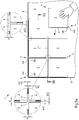
- Fig. 1a to Fig. 1c show several components of a system according to the invention for laying panels in a plan view.
- an elastic swelling tape 5 is shown, which is connected to three joint crosses 4.
- Two joint crosses 4 are attached to opposite ends of the swelling tape 5, while the third joint cross 4 is attached approximately centrally between the two ends of the swelling tape 5.
- the connection between the joint crosses 4 and the swelling tape 5 can be achieved for example by gluing.
- a plate 2 is shown.
- the side lengths a of the plate 2 are greater than the distances b between two adjacent joint crosses 4. So that the joint crosses 4 can be applied to the corners of the plate 2, the swelling tape 5 in the direction of in Fig. 1b shown arrows are stretched.
- Fig. 1a an elastic swelling tape 5 is shown, which is connected to three joint crosses 4.
- Two joint crosses 4 are attached to opposite ends of the swelling tape 5, while the third joint cross 4 is attached approximately centrally between the two ends of the swelling tape 5.
- 1c are the source tape 5 and the associated joint crosses 4 attached to the plate 2.
- the distances b 'between two adjacent joint crosses 4 now correspond to the side lengths a of the plate 2.
- the clamp connection may also be a Bonding - in particular by adhesive tape - are used to attach the swelling tape 5 and the associated joint crosses 4 on the plate 2.
- Fig. 2a shows a system according to the invention for laying panels on a substrate before the expansion of the swellable material in a plan view.
- the system 1 comprises a plurality of plates 2, which - as in Fig. 2a shown as an example - can act around square concrete slabs.
- the plates 2 are to form a floor covering and are laid on a flat surface 3 for this purpose.
- the system 1 also includes a plurality of spacers 4 for adjusting the joint width between the plates 2.
- the spacers 4 are in the in Fig. 2a shown system 1 as a cross-over joints made of plastic with two legs.
- the system 1 comprises an elastic swelling tape 5 made of plastic for sealing the joints between the plates 2 Fig.
- the spacers 4 are arranged at the corners of the plates 2, while the swelling bands 5 are arranged on the sides of the plates.
- the spacers 4 and the swelling tapes 5 are dimensioned and matched to the size of the plates 2 that the spacers 4 and the swelling tapes 5, the plates 2 completely and completely enclose.
- the swelling bands 5 are interrupted by the spacers 4.
- the swelling bands 5 are not interrupted, but extend beyond the spacers 4, for which purpose, for example, corresponding recesses are provided in the spacers 4.
- the swelling bands 5 may have, for example, punched holes for the spacers 4.
- Fig. 2a shown system are used as spacers 4 cross joints made of plastic, which have two legs 4A, 4B, which are arranged at an angle of approximately 90 ° to each other.
- the legs 4A, 4B of the joint cross 4 may have different widths. It can be provided that both legs 4A, 4B of a joint cross 4 have the same width or that the two legs 4A, 4B of a joint cross 4 have different widths.
- the in Fig. 2a shown on the right - enlarged - section shows, for example, a T-shaped joint, in the two joint crosses 4 collide.
- the third joint cross 4 even both legs only half the width d / 2 on.
- the laying of the plates 2 takes place in the in Fig. 2a shown system as follows: First, prefabricated panels 2, joint crosses 4 and 5 swelling bands are provided. Thereafter, three joint crosses 4 and connected to the joint crosses 4 swelling tape 5 are attached to a not yet laid plate 2, for example, by in connection with Fig. 1b and Fig. 1c described bracing or jamming due to elastic deformation of the swelling tape 5. Only after the attachment of the joint cross 4 and the swelling tape 5, the plate 2 is placed on the pad 3. In this way, a subsequent insertion of the swelling tape 5 in the joints is eliminated.
- the number of joint crosses 4 and the swelling bands 5, which are fastened to the plate 2 before laying may vary depending on the laying situation.
- the joint crosses 4 and the swelling bands 5 can be fixed depending on the laying situation at different corners or side surfaces of the plates 2.
- the joint crosses 4 and the swelling bands 5 can be fixed depending on the laying situation at different corners or side surfaces of the plates 2.
- instead of three joint crosses 4 also only two joint crosses 4 or even four joint crosses 4 are attached to a swelling tape 5.
- the length of the swelling tape 5 would have to be adapted according to the number of side surfaces of the plates 2 to be covered.
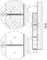
- Fig. 2b is the system off Fig. 2a in cross section along the section plane IIb-IIb Fig. 2a shown.
- Fig. 2b provides with corresponding reference numerals.
- the area of the joints 7 is clearly visible.
- the in Fig. 2b shown on the left - enlarged - section shows a joint cross 4, which is arranged in a joint 7 between two adjacent plates 2.
- the width B of the joint 7 corresponds to the width d of the leg of the joint cross 4.
- the width B of the joint 7 is thus determined by the width of the leg d of the joint cross 4.
- the width B of the joint 7 is greater than the width of the swelling tape 5. This has the consequence that in the gap 7 remains a free gap 8, which is closed only after the (described below) expansion of the swelling tape 5.
- the joint cross 4 and the swelling tape 5 about the same height and are also arranged approximately at the same height.
- the swelling tape 5 has a greater height and / or is arranged higher than the joint cross 4. This has the advantage that the swelling tape 5 can extend continuously above the joint crosses 4 over the entire width of the joint 7 and thus achieve a particularly reliable sealing of the joint 7.
- Another - optical - advantage is that the joint crosses 4 are not visible from above, as they are hidden by the swelling bands 5.
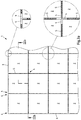
- Fig. 3a shows a system according to the invention for laying plates on a substrate after the expansion of the swellable material in a plan view.
- Fig. 3a provided with corresponding reference numerals.
- An essential difference to that in Fig. 2a shown state is that in Fig. 3a additional plates 2 on the (in Fig. 3a covered) pad 3 were placed and that the swelling bands 5 are expanded and thus the joints 7 between adjacent plates 2 are sealed.
- the Fig. 3a On the right - enlarged - cutouts clearly show that between the joint crosses 4, the source tapes 5 and the plates 2 no free gap is no longer present, creating a reliable seal of the (in Fig. 3a closed) column 7 is reached.
- Fig. 3b is the system off Fig. 3a in cross section along the cutting plane IIIb-IIIb Fig. 3a shown.
- Fig. 3b provides with corresponding reference numerals.
- the area of the joints 7 is clearly visible.
- the in Fig. 3b on the left - enlarged - detail corresponds to the one in Fig. 2b left section shown.
- the in Fig. 3b shown right - also enlarged - section shows a change from the in Fig. 2b
- the detail shown on the right Due to the expansion or expansion of the swelling tape 5, the joint 7 between the adjacent panels 2 was closed. Therefore, the width B of the joint 7 now corresponds to the width of the swelling tape 5. This has the consequence that in the joint 7 no free gap is no longer present.
Landscapes
- Engineering & Computer Science (AREA)
- Architecture (AREA)
- Civil Engineering (AREA)
- Structural Engineering (AREA)
- Chemical & Material Sciences (AREA)
- Ceramic Engineering (AREA)
- Road Paving Structures (AREA)
Priority Applications (1)
| Application Number | Priority Date | Filing Date | Title |
|---|---|---|---|
| PL17176807T PL3263769T3 (pl) | 2016-06-28 | 2017-06-20 | System i sposób układania płyt na podłożu |
Applications Claiming Priority (1)
| Application Number | Priority Date | Filing Date | Title |
|---|---|---|---|
| DE102016111828.1A DE102016111828A1 (de) | 2016-06-28 | 2016-06-28 | System und Verfahren zum Verlegen von Platten auf einer Unterlage |
Publications (2)
| Publication Number | Publication Date |
|---|---|
| EP3263769A1 EP3263769A1 (de) | 2018-01-03 |
| EP3263769B1 true EP3263769B1 (de) | 2018-12-12 |
Family
ID=59093427
Family Applications (1)
| Application Number | Title | Priority Date | Filing Date |
|---|---|---|---|
| EP17176807.0A Active EP3263769B1 (de) | 2016-06-28 | 2017-06-20 | System und verfahren zum verlegen von platten auf einer unterlage |
Country Status (4)
| Country | Link |
|---|---|
| EP (1) | EP3263769B1 (pl) |
| DE (1) | DE102016111828A1 (pl) |
| HU (1) | HUE042108T2 (pl) |
| PL (1) | PL3263769T3 (pl) |
Families Citing this family (3)
| Publication number | Priority date | Publication date | Assignee | Title |
|---|---|---|---|---|
| CN108505716A (zh) * | 2018-04-23 | 2018-09-07 | 中国二十二冶集团有限公司 | 解决相邻地板砖翘曲不平的方法 |
| CN111075148B (zh) * | 2020-01-03 | 2021-09-24 | 江苏肯帝亚木业有限公司 | 一种防水型仿瓷镜面高分子复合地板及施工方法 |
| AT524503B1 (de) * | 2020-12-14 | 2025-04-15 | Michael Friedl Alfred | Pflastersystem mit Fugenkreuzen mit Haken und Pflastersteinen |
Family Cites Families (8)
| Publication number | Priority date | Publication date | Assignee | Title |
|---|---|---|---|---|
| DE3133271A1 (de) | 1981-08-22 | 1983-03-03 | Irbit Holding AG, 1701 Fribourg | Zu einer rolle aufgewickelter schaumstoff-streifen, vorzugsweise zu abdichtungszwecken |
| DE9403780U1 (de) * | 1994-03-07 | 1995-07-06 | Permesang, Claus, Dipl.-Ing., 54290 Trier | Pflaster |
| DE29814695U1 (de) * | 1998-08-17 | 1999-12-30 | Betonwerk Kwade GmbH & Co. KG, 48465 Schüttorf | Betonelement |
| DE10161482A1 (de) * | 2001-12-14 | 2003-07-03 | Johannes Lewe | Bodenbelagselement sowie Verfahren zum Verlegen von Bodenbelagselementen mit dichten Fugen |
| DE202010005542U1 (de) | 2010-06-01 | 2011-10-19 | Walter Gutjahr | Pflaster- oder Plattenbelag |
| DE202010008322U1 (de) * | 2010-08-20 | 2011-11-21 | Tremco Illbruck Produktion Gmbh | Schaumstoff-Dichtband in einer Bauwerksfuge und Schaumstoff-Dichtband |
| DE202011000596U1 (de) * | 2011-03-16 | 2012-06-18 | Stekox Gmbh | Fugendichtungsprofil für Betonbeläge |
| DE202011103629U1 (de) * | 2011-07-20 | 2012-03-01 | Folag Ag | Abstandhalter für lose verlegte Platten |
-
2016
- 2016-06-28 DE DE102016111828.1A patent/DE102016111828A1/de not_active Withdrawn
-
2017
- 2017-06-20 EP EP17176807.0A patent/EP3263769B1/de active Active
- 2017-06-20 PL PL17176807T patent/PL3263769T3/pl unknown
- 2017-06-20 HU HUE17176807A patent/HUE042108T2/hu unknown
Also Published As
| Publication number | Publication date |
|---|---|
| DE102016111828A1 (de) | 2017-12-28 |
| HUE042108T2 (hu) | 2019-06-28 |
| PL3263769T3 (pl) | 2019-04-30 |
| EP3263769A1 (de) | 2018-01-03 |
Similar Documents
| Publication | Publication Date | Title |
|---|---|---|
| EP3521557B1 (de) | Multifunktionsrahmen für röhrenartige bauwerke | |
| DE69907752T2 (de) | Verfahren und vorrichtung zum abdichten von fugen oder rissen in hydraulischen werken, beton und mauerwerk | |
| DE19501384C9 (de) | Dichtungsvorrichtung zum Abdichten von Betonierfugen | |
| EP0922814A2 (de) | Dichtungsvorrichtung zum Abdichten von Betonfugen | |
| EP3263769B1 (de) | System und verfahren zum verlegen von platten auf einer unterlage | |
| DE202010011520U1 (de) | Klettsystem | |
| EP1267035B1 (de) | Verfahren zum Erstellen von abgedichteten unterirdischen Tunnelbauten mit betonierter Innenschale | |
| DE19925573C2 (de) | Dichtungsbahn | |
| DE102012102800B4 (de) | Fugenprofil und Anordnung aus mehreren Fugenprofilen für Fugen in einem Betonbelag | |
| DE2705432A1 (de) | Ausbau fuer stollen, tunnel oder schaechte | |
| DE3800630A1 (de) | Tunnelausbau aus segmenten | |
| DE102006031832A1 (de) | Bauteil und ein Verfahren zur Herstellung eines Bauteils | |
| DE20219324U1 (de) | Gebäudegeschoss | |
| DE3230928A1 (de) | Vorrichtung zur herstellung einer dehnfuge | |
| DE188573C (pl) | ||
| DE19808019A1 (de) | Abdichtbahn | |
| DE3326430A1 (de) | Wiederverwendbare schalung fuer den verbundausbau und hinterfuellverfahren | |
| EP3524744A1 (de) | Pressdichtung, dichtungsanordnung und bauwerk mit pressdichtung | |
| CH395485A (de) | Abdichtung für Bauwerke, aus einem Belag aus flexiblen Kunststoffolien | |
| DE3416297A1 (de) | Verfahren zur herstellung von unterirdischen bauwerken aus betonteilen, anordnung und material zur durchfuehrung dieses verfahrens | |
| DE10136819B4 (de) | Bewehrungselement für flächige Betonteile | |
| DE2516954A1 (de) | Vorrichtung zur befestigung von hinterluefteten fassaden-verkleidungsplatten | |
| DE102020116152A1 (de) | Dachdämm- und Abdichtungssystem | |
| DE8015600U1 (de) | Dichtungsbahn | |
| DE29519411U1 (de) | Fassadenverkleidungselement |
Legal Events
| Date | Code | Title | Description |
|---|---|---|---|
| PUAI | Public reference made under article 153(3) epc to a published international application that has entered the european phase |
Free format text: ORIGINAL CODE: 0009012 |
|
| STAA | Information on the status of an ep patent application or granted ep patent |
Free format text: STATUS: THE APPLICATION HAS BEEN PUBLISHED |
|
| AK | Designated contracting states |
Kind code of ref document: A1 Designated state(s): AL AT BE BG CH CY CZ DE DK EE ES FI FR GB GR HR HU IE IS IT LI LT LU LV MC MK MT NL NO PL PT RO RS SE SI SK SM TR |
|
| AX | Request for extension of the european patent |
Extension state: BA ME |
|
| STAA | Information on the status of an ep patent application or granted ep patent |
Free format text: STATUS: REQUEST FOR EXAMINATION WAS MADE |
|
| 17P | Request for examination filed |
Effective date: 20180626 |
|
| RBV | Designated contracting states (corrected) |
Designated state(s): AL AT BE BG CH CY CZ DE DK EE ES FI FR GB GR HR HU IE IS IT LI LT LU LV MC MK MT NL NO PL PT RO RS SE SI SK SM TR |
|
| GRAP | Despatch of communication of intention to grant a patent |
Free format text: ORIGINAL CODE: EPIDOSNIGR1 |
|
| STAA | Information on the status of an ep patent application or granted ep patent |
Free format text: STATUS: GRANT OF PATENT IS INTENDED |
|
| INTG | Intention to grant announced |
Effective date: 20180817 |
|
| GRAS | Grant fee paid |
Free format text: ORIGINAL CODE: EPIDOSNIGR3 |
|
| GRAA | (expected) grant |
Free format text: ORIGINAL CODE: 0009210 |
|
| STAA | Information on the status of an ep patent application or granted ep patent |
Free format text: STATUS: THE PATENT HAS BEEN GRANTED |
|
| AK | Designated contracting states |
Kind code of ref document: B1 Designated state(s): AL AT BE BG CH CY CZ DE DK EE ES FI FR GB GR HR HU IE IS IT LI LT LU LV MC MK MT NL NO PL PT RO RS SE SI SK SM TR |
|
| REG | Reference to a national code |
Ref country code: GB Ref legal event code: FG4D Free format text: NOT ENGLISH |
|
| REG | Reference to a national code |
Ref country code: CH Ref legal event code: EP |
|
| REG | Reference to a national code |
Ref country code: AT Ref legal event code: REF Ref document number: 1076125 Country of ref document: AT Kind code of ref document: T Effective date: 20181215 |
|
| REG | Reference to a national code |
Ref country code: DE Ref legal event code: R096 Ref document number: 502017000487 Country of ref document: DE |
|
| REG | Reference to a national code |
Ref country code: IE Ref legal event code: FG4D Free format text: LANGUAGE OF EP DOCUMENT: GERMAN |
|
| REG | Reference to a national code |
Ref country code: CH Ref legal event code: NV Representative=s name: SCHMAUDER AND PARTNER AG PATENT- UND MARKENANW, CH |
|
| REG | Reference to a national code |
Ref country code: NL Ref legal event code: FP |
|
| REG | Reference to a national code |
Ref country code: LT Ref legal event code: MG4D |
|
| PG25 | Lapsed in a contracting state [announced via postgrant information from national office to epo] |
Ref country code: FI Free format text: LAPSE BECAUSE OF FAILURE TO SUBMIT A TRANSLATION OF THE DESCRIPTION OR TO PAY THE FEE WITHIN THE PRESCRIBED TIME-LIMIT Effective date: 20181212 Ref country code: NO Free format text: LAPSE BECAUSE OF FAILURE TO SUBMIT A TRANSLATION OF THE DESCRIPTION OR TO PAY THE FEE WITHIN THE PRESCRIBED TIME-LIMIT Effective date: 20190312 Ref country code: LV Free format text: LAPSE BECAUSE OF FAILURE TO SUBMIT A TRANSLATION OF THE DESCRIPTION OR TO PAY THE FEE WITHIN THE PRESCRIBED TIME-LIMIT Effective date: 20181212 Ref country code: HR Free format text: LAPSE BECAUSE OF FAILURE TO SUBMIT A TRANSLATION OF THE DESCRIPTION OR TO PAY THE FEE WITHIN THE PRESCRIBED TIME-LIMIT Effective date: 20181212 Ref country code: LT Free format text: LAPSE BECAUSE OF FAILURE TO SUBMIT A TRANSLATION OF THE DESCRIPTION OR TO PAY THE FEE WITHIN THE PRESCRIBED TIME-LIMIT Effective date: 20181212 Ref country code: BG Free format text: LAPSE BECAUSE OF FAILURE TO SUBMIT A TRANSLATION OF THE DESCRIPTION OR TO PAY THE FEE WITHIN THE PRESCRIBED TIME-LIMIT Effective date: 20190312 |
|
| PG25 | Lapsed in a contracting state [announced via postgrant information from national office to epo] |
Ref country code: AL Free format text: LAPSE BECAUSE OF FAILURE TO SUBMIT A TRANSLATION OF THE DESCRIPTION OR TO PAY THE FEE WITHIN THE PRESCRIBED TIME-LIMIT Effective date: 20181212 Ref country code: RS Free format text: LAPSE BECAUSE OF FAILURE TO SUBMIT A TRANSLATION OF THE DESCRIPTION OR TO PAY THE FEE WITHIN THE PRESCRIBED TIME-LIMIT Effective date: 20181212 Ref country code: GR Free format text: LAPSE BECAUSE OF FAILURE TO SUBMIT A TRANSLATION OF THE DESCRIPTION OR TO PAY THE FEE WITHIN THE PRESCRIBED TIME-LIMIT Effective date: 20190313 Ref country code: SE Free format text: LAPSE BECAUSE OF FAILURE TO SUBMIT A TRANSLATION OF THE DESCRIPTION OR TO PAY THE FEE WITHIN THE PRESCRIBED TIME-LIMIT Effective date: 20181212 |
|
| REG | Reference to a national code |
Ref country code: HU Ref legal event code: AG4A Ref document number: E042108 Country of ref document: HU |
|
| PG25 | Lapsed in a contracting state [announced via postgrant information from national office to epo] |
Ref country code: CZ Free format text: LAPSE BECAUSE OF FAILURE TO SUBMIT A TRANSLATION OF THE DESCRIPTION OR TO PAY THE FEE WITHIN THE PRESCRIBED TIME-LIMIT Effective date: 20181212 Ref country code: ES Free format text: LAPSE BECAUSE OF FAILURE TO SUBMIT A TRANSLATION OF THE DESCRIPTION OR TO PAY THE FEE WITHIN THE PRESCRIBED TIME-LIMIT Effective date: 20181212 Ref country code: PT Free format text: LAPSE BECAUSE OF FAILURE TO SUBMIT A TRANSLATION OF THE DESCRIPTION OR TO PAY THE FEE WITHIN THE PRESCRIBED TIME-LIMIT Effective date: 20190412 |
|
| PG25 | Lapsed in a contracting state [announced via postgrant information from national office to epo] |
Ref country code: SM Free format text: LAPSE BECAUSE OF FAILURE TO SUBMIT A TRANSLATION OF THE DESCRIPTION OR TO PAY THE FEE WITHIN THE PRESCRIBED TIME-LIMIT Effective date: 20181212 Ref country code: EE Free format text: LAPSE BECAUSE OF FAILURE TO SUBMIT A TRANSLATION OF THE DESCRIPTION OR TO PAY THE FEE WITHIN THE PRESCRIBED TIME-LIMIT Effective date: 20181212 Ref country code: RO Free format text: LAPSE BECAUSE OF FAILURE TO SUBMIT A TRANSLATION OF THE DESCRIPTION OR TO PAY THE FEE WITHIN THE PRESCRIBED TIME-LIMIT Effective date: 20181212 Ref country code: IS Free format text: LAPSE BECAUSE OF FAILURE TO SUBMIT A TRANSLATION OF THE DESCRIPTION OR TO PAY THE FEE WITHIN THE PRESCRIBED TIME-LIMIT Effective date: 20190412 Ref country code: SK Free format text: LAPSE BECAUSE OF FAILURE TO SUBMIT A TRANSLATION OF THE DESCRIPTION OR TO PAY THE FEE WITHIN THE PRESCRIBED TIME-LIMIT Effective date: 20181212 |
|
| REG | Reference to a national code |
Ref country code: DE Ref legal event code: R097 Ref document number: 502017000487 Country of ref document: DE |
|
| PLBE | No opposition filed within time limit |
Free format text: ORIGINAL CODE: 0009261 |
|
| STAA | Information on the status of an ep patent application or granted ep patent |
Free format text: STATUS: NO OPPOSITION FILED WITHIN TIME LIMIT |
|
| PG25 | Lapsed in a contracting state [announced via postgrant information from national office to epo] |
Ref country code: DK Free format text: LAPSE BECAUSE OF FAILURE TO SUBMIT A TRANSLATION OF THE DESCRIPTION OR TO PAY THE FEE WITHIN THE PRESCRIBED TIME-LIMIT Effective date: 20181212 |
|
| 26N | No opposition filed |
Effective date: 20190913 |
|
| PG25 | Lapsed in a contracting state [announced via postgrant information from national office to epo] |
Ref country code: MC Free format text: LAPSE BECAUSE OF FAILURE TO SUBMIT A TRANSLATION OF THE DESCRIPTION OR TO PAY THE FEE WITHIN THE PRESCRIBED TIME-LIMIT Effective date: 20181212 |
|
| PG25 | Lapsed in a contracting state [announced via postgrant information from national office to epo] |
Ref country code: TR Free format text: LAPSE BECAUSE OF FAILURE TO SUBMIT A TRANSLATION OF THE DESCRIPTION OR TO PAY THE FEE WITHIN THE PRESCRIBED TIME-LIMIT Effective date: 20181212 |
|
| PG25 | Lapsed in a contracting state [announced via postgrant information from national office to epo] |
Ref country code: LU Free format text: LAPSE BECAUSE OF NON-PAYMENT OF DUE FEES Effective date: 20190620 |
|
| PG25 | Lapsed in a contracting state [announced via postgrant information from national office to epo] |
Ref country code: CY Free format text: LAPSE BECAUSE OF FAILURE TO SUBMIT A TRANSLATION OF THE DESCRIPTION OR TO PAY THE FEE WITHIN THE PRESCRIBED TIME-LIMIT Effective date: 20181212 |
|
| PG25 | Lapsed in a contracting state [announced via postgrant information from national office to epo] |
Ref country code: MT Free format text: LAPSE BECAUSE OF FAILURE TO SUBMIT A TRANSLATION OF THE DESCRIPTION OR TO PAY THE FEE WITHIN THE PRESCRIBED TIME-LIMIT Effective date: 20181212 |
|
| PG25 | Lapsed in a contracting state [announced via postgrant information from national office to epo] |
Ref country code: SI Free format text: LAPSE BECAUSE OF FAILURE TO SUBMIT A TRANSLATION OF THE DESCRIPTION OR TO PAY THE FEE WITHIN THE PRESCRIBED TIME-LIMIT Effective date: 20181212 |
|
| PG25 | Lapsed in a contracting state [announced via postgrant information from national office to epo] |
Ref country code: MK Free format text: LAPSE BECAUSE OF FAILURE TO SUBMIT A TRANSLATION OF THE DESCRIPTION OR TO PAY THE FEE WITHIN THE PRESCRIBED TIME-LIMIT Effective date: 20181212 |
|
| PGFP | Annual fee paid to national office [announced via postgrant information from national office to epo] |
Ref country code: IE Payment date: 20220623 Year of fee payment: 6 Ref country code: HU Payment date: 20220515 Year of fee payment: 6 Ref country code: GB Payment date: 20220623 Year of fee payment: 6 |
|
| P01 | Opt-out of the competence of the unified patent court (upc) registered |
Effective date: 20230515 |
|
| GBPC | Gb: european patent ceased through non-payment of renewal fee |
Effective date: 20230620 |
|
| REG | Reference to a national code |
Ref country code: IE Ref legal event code: MM4A |
|
| PG25 | Lapsed in a contracting state [announced via postgrant information from national office to epo] |
Ref country code: IE Free format text: LAPSE BECAUSE OF NON-PAYMENT OF DUE FEES Effective date: 20230620 |
|
| PG25 | Lapsed in a contracting state [announced via postgrant information from national office to epo] |
Ref country code: IE Free format text: LAPSE BECAUSE OF NON-PAYMENT OF DUE FEES Effective date: 20230620 Ref country code: HU Free format text: LAPSE BECAUSE OF NON-PAYMENT OF DUE FEES Effective date: 20230621 Ref country code: GB Free format text: LAPSE BECAUSE OF NON-PAYMENT OF DUE FEES Effective date: 20230620 |
|
| PGFP | Annual fee paid to national office [announced via postgrant information from national office to epo] |
Ref country code: PL Payment date: 20250605 Year of fee payment: 9 Ref country code: DE Payment date: 20250624 Year of fee payment: 9 |
|
| PGFP | Annual fee paid to national office [announced via postgrant information from national office to epo] |
Ref country code: NL Payment date: 20250624 Year of fee payment: 9 Ref country code: BE Payment date: 20250624 Year of fee payment: 9 |
|
| PGFP | Annual fee paid to national office [announced via postgrant information from national office to epo] |
Ref country code: FR Payment date: 20250625 Year of fee payment: 9 |
|
| PGFP | Annual fee paid to national office [announced via postgrant information from national office to epo] |
Ref country code: AT Payment date: 20250626 Year of fee payment: 9 |
|
| PGFP | Annual fee paid to national office [announced via postgrant information from national office to epo] |
Ref country code: IT Payment date: 20250626 Year of fee payment: 9 |
|
| PGFP | Annual fee paid to national office [announced via postgrant information from national office to epo] |
Ref country code: CH Payment date: 20250701 Year of fee payment: 9 |