EP3239805B1 - Gehäuseteil für ein elektronisches gerät - Google Patents
Gehäuseteil für ein elektronisches gerät Download PDFInfo
- Publication number
- EP3239805B1 EP3239805B1 EP17167953.3A EP17167953A EP3239805B1 EP 3239805 B1 EP3239805 B1 EP 3239805B1 EP 17167953 A EP17167953 A EP 17167953A EP 3239805 B1 EP3239805 B1 EP 3239805B1
- Authority
- EP
- European Patent Office
- Prior art keywords
- chassis
- laminated sheet
- thermoplastic resin
- parts
- female screw
- Prior art date
- Legal status (The legal status is an assumption and is not a legal conclusion. Google has not performed a legal analysis and makes no representation as to the accuracy of the status listed.)
- Active
Links
Images

Classifications
-
- G—PHYSICS
- G06—COMPUTING OR CALCULATING; COUNTING
- G06F—ELECTRIC DIGITAL DATA PROCESSING
- G06F1/00—Details not covered by groups G06F3/00 - G06F13/00 and G06F21/00
- G06F1/16—Constructional details or arrangements
- G06F1/1613—Constructional details or arrangements for portable computers
- G06F1/1633—Constructional details or arrangements of portable computers not specific to the type of enclosures covered by groups G06F1/1615 - G06F1/1626
-
- G—PHYSICS
- G06—COMPUTING OR CALCULATING; COUNTING
- G06F—ELECTRIC DIGITAL DATA PROCESSING
- G06F1/00—Details not covered by groups G06F3/00 - G06F13/00 and G06F21/00
- G06F1/16—Constructional details or arrangements
- G06F1/1613—Constructional details or arrangements for portable computers
- G06F1/1615—Constructional details or arrangements for portable computers with several enclosures having relative motions, each enclosure supporting at least one I/O or computing function
- G06F1/1616—Constructional details or arrangements for portable computers with several enclosures having relative motions, each enclosure supporting at least one I/O or computing function with folding flat displays, e.g. laptop computers or notebooks having a clamshell configuration, with body parts pivoting to an open position around an axis parallel to the plane they define in closed position
-
- B—PERFORMING OPERATIONS; TRANSPORTING
- B29—WORKING OF PLASTICS; WORKING OF SUBSTANCES IN A PLASTIC STATE IN GENERAL
- B29C—SHAPING OR JOINING OF PLASTICS; SHAPING OF MATERIAL IN A PLASTIC STATE, NOT OTHERWISE PROVIDED FOR; AFTER-TREATMENT OF THE SHAPED PRODUCTS, e.g. REPAIRING
- B29C70/00—Shaping composites, i.e. plastics material comprising reinforcements, fillers or preformed parts, e.g. inserts
- B29C70/04—Shaping composites, i.e. plastics material comprising reinforcements, fillers or preformed parts, e.g. inserts comprising reinforcements only, e.g. self-reinforcing plastics
- B29C70/06—Fibrous reinforcements only
- B29C70/08—Fibrous reinforcements only comprising combinations of different forms of fibrous reinforcements incorporated in matrix material, forming one or more layers, and with or without non-reinforced layers
- B29C70/086—Fibrous reinforcements only comprising combinations of different forms of fibrous reinforcements incorporated in matrix material, forming one or more layers, and with or without non-reinforced layers and with one or more layers of pure plastics material, e.g. foam layers
-
- B—PERFORMING OPERATIONS; TRANSPORTING
- B32—LAYERED PRODUCTS
- B32B—LAYERED PRODUCTS, i.e. PRODUCTS BUILT-UP OF STRATA OF FLAT OR NON-FLAT, e.g. CELLULAR OR HONEYCOMB, FORM
- B32B3/00—Layered products comprising a layer with external or internal discontinuities or unevennesses, or a layer of non-planar shape; Layered products comprising a layer having particular features of form
- B32B3/02—Layered products comprising a layer with external or internal discontinuities or unevennesses, or a layer of non-planar shape; Layered products comprising a layer having particular features of form characterised by features of form at particular places, e.g. in edge regions
- B32B3/08—Layered products comprising a layer with external or internal discontinuities or unevennesses, or a layer of non-planar shape; Layered products comprising a layer having particular features of form characterised by features of form at particular places, e.g. in edge regions characterised by added members at particular parts
-
- G—PHYSICS
- G06—COMPUTING OR CALCULATING; COUNTING
- G06F—ELECTRIC DIGITAL DATA PROCESSING
- G06F1/00—Details not covered by groups G06F3/00 - G06F13/00 and G06F21/00
- G06F1/16—Constructional details or arrangements
- G06F1/1613—Constructional details or arrangements for portable computers
- G06F1/1628—Enclosures for carrying portable computers with peripheral devices, e.g. cases for a laptop and a printer
-
- B—PERFORMING OPERATIONS; TRANSPORTING
- B29—WORKING OF PLASTICS; WORKING OF SUBSTANCES IN A PLASTIC STATE IN GENERAL
- B29C—SHAPING OR JOINING OF PLASTICS; SHAPING OF MATERIAL IN A PLASTIC STATE, NOT OTHERWISE PROVIDED FOR; AFTER-TREATMENT OF THE SHAPED PRODUCTS, e.g. REPAIRING
- B29C70/00—Shaping composites, i.e. plastics material comprising reinforcements, fillers or preformed parts, e.g. inserts
- B29C70/04—Shaping composites, i.e. plastics material comprising reinforcements, fillers or preformed parts, e.g. inserts comprising reinforcements only, e.g. self-reinforcing plastics
-
- B—PERFORMING OPERATIONS; TRANSPORTING
- B32—LAYERED PRODUCTS
- B32B—LAYERED PRODUCTS, i.e. PRODUCTS BUILT-UP OF STRATA OF FLAT OR NON-FLAT, e.g. CELLULAR OR HONEYCOMB, FORM
- B32B27/00—Layered products comprising a layer of synthetic resin
-
- B—PERFORMING OPERATIONS; TRANSPORTING
- B32—LAYERED PRODUCTS
- B32B—LAYERED PRODUCTS, i.e. PRODUCTS BUILT-UP OF STRATA OF FLAT OR NON-FLAT, e.g. CELLULAR OR HONEYCOMB, FORM
- B32B27/00—Layered products comprising a layer of synthetic resin
- B32B27/06—Layered products comprising a layer of synthetic resin as the main or only constituent of a layer, which is next to another layer of the same or of a different material
- B32B27/065—Layered products comprising a layer of synthetic resin as the main or only constituent of a layer, which is next to another layer of the same or of a different material of foam
-
- B—PERFORMING OPERATIONS; TRANSPORTING
- B32—LAYERED PRODUCTS
- B32B—LAYERED PRODUCTS, i.e. PRODUCTS BUILT-UP OF STRATA OF FLAT OR NON-FLAT, e.g. CELLULAR OR HONEYCOMB, FORM
- B32B27/00—Layered products comprising a layer of synthetic resin
- B32B27/06—Layered products comprising a layer of synthetic resin as the main or only constituent of a layer, which is next to another layer of the same or of a different material
- B32B27/08—Layered products comprising a layer of synthetic resin as the main or only constituent of a layer, which is next to another layer of the same or of a different material of synthetic resin
-
- B—PERFORMING OPERATIONS; TRANSPORTING
- B32—LAYERED PRODUCTS
- B32B—LAYERED PRODUCTS, i.e. PRODUCTS BUILT-UP OF STRATA OF FLAT OR NON-FLAT, e.g. CELLULAR OR HONEYCOMB, FORM
- B32B27/00—Layered products comprising a layer of synthetic resin
- B32B27/38—Layered products comprising a layer of synthetic resin comprising epoxy resins
-
- B—PERFORMING OPERATIONS; TRANSPORTING
- B32—LAYERED PRODUCTS
- B32B—LAYERED PRODUCTS, i.e. PRODUCTS BUILT-UP OF STRATA OF FLAT OR NON-FLAT, e.g. CELLULAR OR HONEYCOMB, FORM
- B32B3/00—Layered products comprising a layer with external or internal discontinuities or unevennesses, or a layer of non-planar shape; Layered products comprising a layer having particular features of form
- B32B3/26—Layered products comprising a layer with external or internal discontinuities or unevennesses, or a layer of non-planar shape; Layered products comprising a layer having particular features of form characterised by a particular shape of the outline of the cross-section of a continuous layer; characterised by a layer with cavities or internal voids ; characterised by an apertured layer
- B32B3/266—Layered products comprising a layer with external or internal discontinuities or unevennesses, or a layer of non-planar shape; Layered products comprising a layer having particular features of form characterised by a particular shape of the outline of the cross-section of a continuous layer; characterised by a layer with cavities or internal voids ; characterised by an apertured layer characterised by an apertured layer, the apertures going through the whole thickness of the layer, e.g. expanded metal, perforated layer, slit layer regular cells B32B3/12
-
- B—PERFORMING OPERATIONS; TRANSPORTING
- B32—LAYERED PRODUCTS
- B32B—LAYERED PRODUCTS, i.e. PRODUCTS BUILT-UP OF STRATA OF FLAT OR NON-FLAT, e.g. CELLULAR OR HONEYCOMB, FORM
- B32B5/00—Layered products characterised by the non- homogeneity or physical structure, i.e. comprising a fibrous, filamentary, particulate or foam layer; Layered products characterised by having a layer differing constitutionally or physically in different parts
- B32B5/18—Layered products characterised by the non- homogeneity or physical structure, i.e. comprising a fibrous, filamentary, particulate or foam layer; Layered products characterised by having a layer differing constitutionally or physically in different parts characterised by features of a layer of foamed material
-
- B—PERFORMING OPERATIONS; TRANSPORTING
- B32—LAYERED PRODUCTS
- B32B—LAYERED PRODUCTS, i.e. PRODUCTS BUILT-UP OF STRATA OF FLAT OR NON-FLAT, e.g. CELLULAR OR HONEYCOMB, FORM
- B32B5/00—Layered products characterised by the non- homogeneity or physical structure, i.e. comprising a fibrous, filamentary, particulate or foam layer; Layered products characterised by having a layer differing constitutionally or physically in different parts
- B32B5/22—Layered products characterised by the non- homogeneity or physical structure, i.e. comprising a fibrous, filamentary, particulate or foam layer; Layered products characterised by having a layer differing constitutionally or physically in different parts characterised by the presence of two or more layers which are next to each other and are fibrous, filamentary, formed of particles or foamed
- B32B5/24—Layered products characterised by the non- homogeneity or physical structure, i.e. comprising a fibrous, filamentary, particulate or foam layer; Layered products characterised by having a layer differing constitutionally or physically in different parts characterised by the presence of two or more layers which are next to each other and are fibrous, filamentary, formed of particles or foamed one layer being a fibrous or filamentary layer
- B32B5/245—Layered products characterised by the non- homogeneity or physical structure, i.e. comprising a fibrous, filamentary, particulate or foam layer; Layered products characterised by having a layer differing constitutionally or physically in different parts characterised by the presence of two or more layers which are next to each other and are fibrous, filamentary, formed of particles or foamed one layer being a fibrous or filamentary layer another layer next to it being a foam layer
-
- B—PERFORMING OPERATIONS; TRANSPORTING
- B32—LAYERED PRODUCTS
- B32B—LAYERED PRODUCTS, i.e. PRODUCTS BUILT-UP OF STRATA OF FLAT OR NON-FLAT, e.g. CELLULAR OR HONEYCOMB, FORM
- B32B7/00—Layered products characterised by the relation between layers; Layered products characterised by the relative orientation of features between layers, or by the relative values of a measurable parameter between layers, i.e. products comprising layers having different physical, chemical or physicochemical properties; Layered products characterised by the interconnection of layers
- B32B7/04—Interconnection of layers
- B32B7/08—Interconnection of layers by mechanical means
-
- G—PHYSICS
- G06—COMPUTING OR CALCULATING; COUNTING
- G06F—ELECTRIC DIGITAL DATA PROCESSING
- G06F1/00—Details not covered by groups G06F3/00 - G06F13/00 and G06F21/00
- G06F1/16—Constructional details or arrangements
- G06F1/1613—Constructional details or arrangements for portable computers
- G06F1/1633—Constructional details or arrangements of portable computers not specific to the type of enclosures covered by groups G06F1/1615 - G06F1/1626
- G06F1/1637—Details related to the display arrangement, including those related to the mounting of the display in the housing
-
- G—PHYSICS
- G06—COMPUTING OR CALCULATING; COUNTING
- G06F—ELECTRIC DIGITAL DATA PROCESSING
- G06F1/00—Details not covered by groups G06F3/00 - G06F13/00 and G06F21/00
- G06F1/16—Constructional details or arrangements
- G06F1/1613—Constructional details or arrangements for portable computers
- G06F1/1633—Constructional details or arrangements of portable computers not specific to the type of enclosures covered by groups G06F1/1615 - G06F1/1626
- G06F1/1662—Details related to the integrated keyboard
- G06F1/1667—Arrangements for adjusting the tilt angle of the integrated keyboard independently from the main body
-
- G—PHYSICS
- G06—COMPUTING OR CALCULATING; COUNTING
- G06F—ELECTRIC DIGITAL DATA PROCESSING
- G06F1/00—Details not covered by groups G06F3/00 - G06F13/00 and G06F21/00
- G06F1/16—Constructional details or arrangements
- G06F1/1613—Constructional details or arrangements for portable computers
- G06F1/1633—Constructional details or arrangements of portable computers not specific to the type of enclosures covered by groups G06F1/1615 - G06F1/1626
- G06F1/1675—Miscellaneous details related to the relative movement between the different enclosures or enclosure parts
- G06F1/1681—Details related solely to hinges
-
- B—PERFORMING OPERATIONS; TRANSPORTING
- B32—LAYERED PRODUCTS
- B32B—LAYERED PRODUCTS, i.e. PRODUCTS BUILT-UP OF STRATA OF FLAT OR NON-FLAT, e.g. CELLULAR OR HONEYCOMB, FORM
- B32B2250/00—Layers arrangement
- B32B2250/03—3 layers
-
- B—PERFORMING OPERATIONS; TRANSPORTING
- B32—LAYERED PRODUCTS
- B32B—LAYERED PRODUCTS, i.e. PRODUCTS BUILT-UP OF STRATA OF FLAT OR NON-FLAT, e.g. CELLULAR OR HONEYCOMB, FORM
- B32B2250/00—Layers arrangement
- B32B2250/05—5 or more layers
-
- B—PERFORMING OPERATIONS; TRANSPORTING
- B32—LAYERED PRODUCTS
- B32B—LAYERED PRODUCTS, i.e. PRODUCTS BUILT-UP OF STRATA OF FLAT OR NON-FLAT, e.g. CELLULAR OR HONEYCOMB, FORM
- B32B2250/00—Layers arrangement
- B32B2250/40—Symmetrical or sandwich layers, e.g. ABA, ABCBA, ABCCBA
-
- B—PERFORMING OPERATIONS; TRANSPORTING
- B32—LAYERED PRODUCTS
- B32B—LAYERED PRODUCTS, i.e. PRODUCTS BUILT-UP OF STRATA OF FLAT OR NON-FLAT, e.g. CELLULAR OR HONEYCOMB, FORM
- B32B2260/00—Layered product comprising an impregnated, embedded, or bonded layer wherein the layer comprises an impregnation, embedding, or binder material
- B32B2260/02—Composition of the impregnated, bonded or embedded layer
- B32B2260/021—Fibrous or filamentary layer
- B32B2260/023—Two or more layers
-
- B—PERFORMING OPERATIONS; TRANSPORTING
- B32—LAYERED PRODUCTS
- B32B—LAYERED PRODUCTS, i.e. PRODUCTS BUILT-UP OF STRATA OF FLAT OR NON-FLAT, e.g. CELLULAR OR HONEYCOMB, FORM
- B32B2260/00—Layered product comprising an impregnated, embedded, or bonded layer wherein the layer comprises an impregnation, embedding, or binder material
- B32B2260/04—Impregnation, embedding, or binder material
- B32B2260/046—Synthetic resin
-
- B—PERFORMING OPERATIONS; TRANSPORTING
- B32—LAYERED PRODUCTS
- B32B—LAYERED PRODUCTS, i.e. PRODUCTS BUILT-UP OF STRATA OF FLAT OR NON-FLAT, e.g. CELLULAR OR HONEYCOMB, FORM
- B32B2262/00—Composition or structural features of fibres which form a fibrous or filamentary layer or are present as additives
- B32B2262/10—Inorganic fibres
- B32B2262/101—Glass fibres
-
- B—PERFORMING OPERATIONS; TRANSPORTING
- B32—LAYERED PRODUCTS
- B32B—LAYERED PRODUCTS, i.e. PRODUCTS BUILT-UP OF STRATA OF FLAT OR NON-FLAT, e.g. CELLULAR OR HONEYCOMB, FORM
- B32B2262/00—Composition or structural features of fibres which form a fibrous or filamentary layer or are present as additives
- B32B2262/10—Inorganic fibres
- B32B2262/103—Metal fibres
-
- B—PERFORMING OPERATIONS; TRANSPORTING
- B32—LAYERED PRODUCTS
- B32B—LAYERED PRODUCTS, i.e. PRODUCTS BUILT-UP OF STRATA OF FLAT OR NON-FLAT, e.g. CELLULAR OR HONEYCOMB, FORM
- B32B2262/00—Composition or structural features of fibres which form a fibrous or filamentary layer or are present as additives
- B32B2262/10—Inorganic fibres
- B32B2262/106—Carbon fibres, e.g. graphite fibres
-
- B—PERFORMING OPERATIONS; TRANSPORTING
- B32—LAYERED PRODUCTS
- B32B—LAYERED PRODUCTS, i.e. PRODUCTS BUILT-UP OF STRATA OF FLAT OR NON-FLAT, e.g. CELLULAR OR HONEYCOMB, FORM
- B32B2266/00—Composition of foam
- B32B2266/02—Organic
- B32B2266/0214—Materials belonging to B32B27/00
- B32B2266/025—Polyolefin
-
- B—PERFORMING OPERATIONS; TRANSPORTING
- B32—LAYERED PRODUCTS
- B32B—LAYERED PRODUCTS, i.e. PRODUCTS BUILT-UP OF STRATA OF FLAT OR NON-FLAT, e.g. CELLULAR OR HONEYCOMB, FORM
- B32B2305/00—Condition, form or state of the layers or laminate
- B32B2305/08—Reinforcements
-
- B—PERFORMING OPERATIONS; TRANSPORTING
- B32—LAYERED PRODUCTS
- B32B—LAYERED PRODUCTS, i.e. PRODUCTS BUILT-UP OF STRATA OF FLAT OR NON-FLAT, e.g. CELLULAR OR HONEYCOMB, FORM
- B32B2307/00—Properties of the layers or laminate
- B32B2307/50—Properties of the layers or laminate having particular mechanical properties
- B32B2307/558—Impact strength, toughness
-
- B—PERFORMING OPERATIONS; TRANSPORTING
- B32—LAYERED PRODUCTS
- B32B—LAYERED PRODUCTS, i.e. PRODUCTS BUILT-UP OF STRATA OF FLAT OR NON-FLAT, e.g. CELLULAR OR HONEYCOMB, FORM
- B32B2307/00—Properties of the layers or laminate
- B32B2307/70—Other properties
- B32B2307/732—Dimensional properties
-
- B—PERFORMING OPERATIONS; TRANSPORTING
- B32—LAYERED PRODUCTS
- B32B—LAYERED PRODUCTS, i.e. PRODUCTS BUILT-UP OF STRATA OF FLAT OR NON-FLAT, e.g. CELLULAR OR HONEYCOMB, FORM
- B32B2457/00—Electrical equipment
-
- B—PERFORMING OPERATIONS; TRANSPORTING
- B32—LAYERED PRODUCTS
- B32B—LAYERED PRODUCTS, i.e. PRODUCTS BUILT-UP OF STRATA OF FLAT OR NON-FLAT, e.g. CELLULAR OR HONEYCOMB, FORM
- B32B27/00—Layered products comprising a layer of synthetic resin
- B32B27/12—Layered products comprising a layer of synthetic resin next to a fibrous or filamentary layer
-
- B—PERFORMING OPERATIONS; TRANSPORTING
- B32—LAYERED PRODUCTS
- B32B—LAYERED PRODUCTS, i.e. PRODUCTS BUILT-UP OF STRATA OF FLAT OR NON-FLAT, e.g. CELLULAR OR HONEYCOMB, FORM
- B32B3/00—Layered products comprising a layer with external or internal discontinuities or unevennesses, or a layer of non-planar shape; Layered products comprising a layer having particular features of form
- B32B3/26—Layered products comprising a layer with external or internal discontinuities or unevennesses, or a layer of non-planar shape; Layered products comprising a layer having particular features of form characterised by a particular shape of the outline of the cross-section of a continuous layer; characterised by a layer with cavities or internal voids ; characterised by an apertured layer
- B32B3/30—Layered products comprising a layer with external or internal discontinuities or unevennesses, or a layer of non-planar shape; Layered products comprising a layer having particular features of form characterised by a particular shape of the outline of the cross-section of a continuous layer; characterised by a layer with cavities or internal voids ; characterised by an apertured layer characterised by a layer formed with recesses or projections, e.g. hollows, grooves, protuberances, ribs
-
- G—PHYSICS
- G06—COMPUTING OR CALCULATING; COUNTING
- G06F—ELECTRIC DIGITAL DATA PROCESSING
- G06F1/00—Details not covered by groups G06F3/00 - G06F13/00 and G06F21/00
- G06F1/16—Constructional details or arrangements
- G06F1/1601—Constructional details related to the housing of computer displays, e.g. of CRT monitors, of flat displays
Definitions
- the present invention relates to a member for a chassis which is utilizable as chassis of electronic apparatuses such as a Laptop PC, a tablet PC and so forth and an electronic apparatus using the member for a chassis.
- the chassis of various electronic apparatuses such as a notebook personal computer (the Laptop PC), a tablet type personal computer (the tablet PC), a smartphone, a portable phone and so forth to be light in weight, thin in thickness and high in strength. Accordingly, it is widely practiced to use a sheet-shaped laminated sheet wherein an intermediate layer which is made of a foamed material and so forth has been sandwiched between prepreg sheets (fiber reinforced resin sheets) prepared by impregnating reinforced fibers such as carbon fibers and so forth with a thermosetting resin such as an epoxy resin and so forth in the chassis of the electronic apparatus.
- prepreg sheets fiber reinforced resin sheets
- the laminated sheet When such a laminated sheet is to be used in the chassis of the Laptop PC and so forth, it is requested to perform machining of a desirable shape such as a wall part and so forth at least on a peripheral edge part of the laminated sheet.
- a desirable shape such as a wall part and so forth at least on a peripheral edge part of the laminated sheet.
- the laminated sheet is configured by using a hard fiber reinforced resin sheet, the laminated sheet is low in degree of freedom of shape machining such as bending and so forth.
- the applicant of the present application proposes a configuration wherein a thermoplastic resin has been injection-molded and bonded to an external-form end face of the laminated sheet (see Patent Document 1). Since in this configuration, it is possible to ensure the degree of freedom of shape machining by a thermoplastic resin part which has been bonded to the laminated sheet, it is possible to widely utilize the laminated sheet as the members for chassis of various shapes and specifications.
- Patent Document 1 Japanese Patent Application Laid-Open No. 2013-232052
- the present invention has been made in consideration of the above-mentioned disadvantages of the related art and aims to provide a member for chassis which makes it possible to obtain a high strength and an electronic apparatus using the member for chassis.
- the member for a chassis according to the present invention is a member in accordance with claim 1
- thermoplastic resin which has been extended to the surface of the laminated sheet integrally with the high-strength laminated sheet with high bond strength owing to an anchoring effect by the anchor part by configuring the member for a chassis in this way. Accordingly, for example, in a case where the member for a chassis has been structured such that that the other member or the like has been fixed to the thermoplastic resin which has been extended to the surface of the laminated sheet by adhesive bonding and screw clamping, even when the external force and the shock have been imparted to this part, it is possible to accept the external force and the shock by the high-strength laminated sheet via the anchor part.
- thermoplastic resin which has been extended to the surface of the laminated sheet and/or delamination of this thermoplastic resin from the surface of the laminated sheet is/are suppressed and it is possible to obtain the chassis which is high in strength and high in anti-shock property.
- the member for a chassis may also have such a configuration that a female screw part is provided in a part of the thermoplastic resin which has been extended to the surface of the laminated sheet. Then, for example, even when the load has been concentrated on the female screw part when the chassis of the electronic apparatus and so forth using the member for a chassis concerned has been fallen to the ground and a floor surface, it is possible to prevent the female screw part from being broken because the thermoplastic resin is rigidly bonded to the laminated sheet by the anchor part.
- the female screw part may be configured by a nut which has been positioned and fixed by a boss part which has been formed by using the thermoplastic resin. Also in this case, it is possible to accept the shock and the external force imparted to the nut owing to the anchoring effect of the anchor part and it is possible to ensure the high strength.
- the member for a chassis may also have such a configuration that a plurality of the female screw parts is arranged side by side and the anchor part is arranged at a position between the two mutually adjacent female screw parts.
- the member for a chassis may also have such a configuration that a plurality of the anchor parts is arranged side by side in a direction which is orthogonal to a direction that the two mutually adjacent female screw parts are arranged side by side. Then, for example, when the load which works in a direction orthogonal to the direction that the two mutually adjacent female screw parts are arranged side by side has been applied to each female screw part, it is possible to accept the load by the anchor part which is interposed between the mutually adjacent female screw parts in the more well-balanced state and rigidly.
- the member for a chassis may also have such a configuration that the hole part extends from the surface of the laminated sheet and reaches the intermediate layer and the anchor part has been put into the intermediate layer. Then, the anchor part generates a high anchoring effect also in an out-of-plane direction which is orthogonal to an in-plane direction in addition to the anchoring effect which acts in the in-plane direction between the thermoplastic resin and the laminated sheet which is located under the thermoplastic resin and it is possible to obtain the high bond strength.
- the electronic apparatus according to the present invention is an electronic apparatus according to claim 5.
- the electronic apparatus may also have such a configuration that the electronic apparatus further includes another chassis which has been coupled with the chassis to be openable and closable via a hinge, in which on the member for a chassis, a female screw part is provided in a part of the thermoplastic resin which has been extended to the surface of the laminated sheet and the hinge is screwed and fixed to the female screw part. Then, even in a case where a shock which has been generated, for example, when the electronic apparatus concerned has been fallen has been applied to the female screw part via the hinge, breakage of the female screw part and the thermoplastic resin around the female screw part is avoided by a high bonding action by the anchor part.
- the electronic apparatus may also have such a configuration that a plurality of female screw parts is arranged side by side in a direction along first one end parts of the chassis and the other chassis which have been coupled with each other by the hinge and the anchor part has been provided at a position between the two mutually adjacent female screw parts.
- the electronic apparatus may also have such a configuration that a plurality of the anchor parts is arranged side by side in a direction directing from first end parts of the chassis and the other chassis which have been coupled with each other by the hinge to the opposite-side other end parts of the chassis and the other chassis. Then, the anti-shock property of the electronic apparatus concerned is more improved.
- the electronic apparatus may also have such a configuration that the anchor part is provided in a state where the position thereof deviates from the position of the female screw part in a direction directing from first end parts of the chassis and the other chassis which have been coupled together by the hinge to the opposite-side other end parts of the chassis and the other chassis. Then, it is possible to accept the shock which has been generated when the electronic apparatus has been fallen in the state of directing the other end part on the opposite side of the hinge side downward as the lower end by the anchor part which has been provided in the state where the position thereof deviates from the position of the female screw part in a falling direction of the electronic apparatus in the more well-balanced state.
- the electronic apparatus may also have such a configuration that on the chassis, the other end part on the opposite side of the first end part at which the chassis has been coupled with the other chassis by the hinge projects in a state where the position thereof deviates from the position of the other end part of the other chassis in a direction directing from the first end parts to the other end parts of the chassis and the other chassis. That is, in a case where the electronic apparatus so configured has been fallen in a state of directing the other end part downward as the lower end, the most projected other end part of the chassis comes into abutment on the ground and so forth under the influence of the shock earlier than the other end part of the other chassis.
- thermoplastic resins in which this female screw part has been provided is implanted into the laminated sheet as the anchor part. Therefore, it is possible to accept the load which has acted from the other chassis to the female screw part via the hinge by the high-strength laminated sheet via the anchor part and the female screw part and its surrounding part is effectively prevented from being broken.
- thermoplastic resin which has been extended to the surface of the laminated sheet integrally with the high-strength laminated sheet with the high bond strength owing to the anchoring effect by the anchor part and it is possible to obtain the high strength.
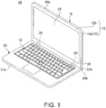
- FIG. 1 is a perspective view illustrating one example of an electronic apparatus 14 which includes a chassis 12 using a member for a chassis 10 according to one embodiment of the present invention.
- a configuration that the chassis 12 which has used the member for a chassis 10 has been used as a lid body 16 of the electronic apparatus 14 which is a Laptop PC is exemplified.
- the electronic apparatus 14 includes an apparatus main body 20 having a keyboard device 18 and the rectangular sheet-shaped lid body 16 having a display device 22 which is configured by a liquid crystal display and so forth.
- the electronic apparatus 14 is a clamshell type apparatus that the lid body 16 has been coupled to the apparatus main body 20 to be openable and closable by left and right hinges 24.
- the apparatus main body 20 is a flat box-shaped chassis and houses various electronic components such as a substrate, an arithmetic processing device, a hard disk device, a memory and so forth which are not illustrated in FIG. 1 .
- the keyboard device 18 is arranged on an upper surface of the apparatus main body 20.
- the lid body 16 includes the chassis 12 formed by superposing and coupling together a rear face cover 12a and a front face cover 12b and is electrically connected with the apparatus main body 20 by a not illustrated cable which has passed through the hinges 24.
- the rear face cover 12a is a cover member which covers side faces and a rear face of the lid body 16 and is configured by the member for a chassis 10 according to the present embodiment.
- the lid body 16 is coupled with the apparatus main body 20 via the hinges 24 which have been screwed and fixed to the rear face cover 12a (also see FIG. 2 ).
- the front face cover 12b is a resinous cover member which covers the front face of the lid body 16 and a hole part through which the display device 22 which is configured by, for example, the liquid crystal display is exposed is formed in most part of the front face cover 12b.
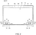
- FIG. 2 is a plan view schematically illustrating one example of the configuration of the rear face cover 12a of the chassis 12 and is the diagram wherein the rear face cover 12a which serves as the rear face of the lid body 16 has been viewed from the inner face side.
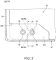
- FIG. 3 is a plan view enlargedly illustrating one example of a wide part 32a and its vicinity of the rear face cover 12a illustrated in FIG. 2 .
- the rear face cover 12a is formed by the member for a chassis 10.
- the member for a chassis 10 includes a laminated sheet 30 which has been formed so as to have a three-layer structure and so as to be light in weight and high in strength and a frame part 32 which has been formed by bonding a thermoplastic resin to an external-form end face 30a of the laminated sheet 30.
- the rear face cover 12a includes a wall part 34 which is formed by using the frame part 32 of the member for a chassis 10 so configured and serves as a peripheral edge part and four side faces of the rear face cover 12a and a sheet-shaped part which supports the rear face of the display device 22 is formed by using the laminated sheet 30.
- the frame part 32 On the chassis 12 (the lid body 16), the frame part 32 is provided with one pair of the left and right wide parts 32a on one edge side (a lower edge in FIG. 2 ) of the rear face cover 12a.
- the hinges 24 are fixed to the left and right wide parts 32a respectively by using a plurality (two screws in FIG. 2 ) of fixing screws 36.
- the frame part 32 is provided with a belt-shaped part 32b which extends in a left-to-right direction on the other edge side (an upper edge in FIG. 2 ) of the rear face cover 12a.
- Antennas 38 for radio communications are arranged in the belt-shaped part 32b.
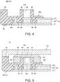
- FIG. 4 is a sectional diagram schematically illustrating one example of a sectional shape along the IV-IV line in FIG. 3 , that is, the sectional diagram in a thickness direction of a section which includes the laminated sheet 30 and the frame part 32 (the wide parts 32a) of the member for a chassis 10.
- FIG. 5 is a sectional diagram illustrating one example of a state where the hinge 24 has been fixed to the member for a chassis 10 illustrated in FIG. 4 by using the fixing screw 36.
- the member for a chassis 10 includes the laminated sheet 30 that an intermediate layer 42 has been arranged between one pair of upper and lower fiber reinforced resin sheets 40 and 41 and the frame part 32 which has been bonded to the external-form end face 30a of the laminated sheet 30.
- Each of the fiber reinforced resin sheets 40 and 41 is a prepreg prepared by impregnating reinforced fibers with a thermosetting resin such as an epoxy resin and so forth and has a sheet thickness of, for example, about 0.3 mm.
- a carbon fiber reinforced resin (CFRP) that carbon fibers have been used as the reinforced fibers is used.
- CFRP carbon fiber reinforced resin
- fibers other than the carbon fibers may be used and various materials such as metal fibers such as stainless fibers and so forth and inorganic fibers such as glass fibers and so forth may be used.
- the intermediate layer 42 is arranged between one pair of the fiber reinforced resin sheets 40 and 41, serves as a soft spacer for isolating these hard fiber reinforced resin sheets 40 and 41 from each other and has a sheet thickness of, for example, about 0.6 mm. Owing to provision of the intermediate layer 42, a section modulus in a sheet thickness direction of the laminated sheet 30 is increased and the laminated sheet 30 has a light-weight and high-strength structure.
- the intermediate layer 42 is configured by, for example, a foamed layer which has been configured by a foamed sheet such as polypropylene and so forth, a fiber layer of the carbon fibers and so forth which have been assembled together with compressible gaps being contained therein and so forth.
- the frame part 32 is bonded to the laminated sheet 30 by injection-molding the thermoplastic resin to the external-form end face 30a of the laminated sheet 30 so configured.
- the thermoplastic resin which forms the frame part 32 for example, a polyethylene resin, a polypropylene resin and so forth may be used and also fiber reinforced resins (for example, GFRP) prepared by containing reinforced fibers such as glass fibers and so forth in these resins may be used.
- the anchoring effect is caused to occur by conducting injection molding so as to put the thermoplastic resin which forms the frame part 32 into the intermediate layer 42 which has been sandwiched between the fiber reinforced resin sheets 40 and 41 and thereby the high bond strength is ensured.
- each wide part 32a to which each hinge 24 has been screwed and fixed with the two fixing screws 36 is formed by extending the thermoplastic resin which has been bonded to the external-form end face 30a of the laminated sheet 30 to the surface (the surface of one fiber reinforced resin sheet 40) of the laminated sheet 30. That is, the wide part 32a is a part formed by providing the thermoplastic resin in the form of a thin sheet on the surface of the laminated sheet 30. Then, screwing and fixing of the hinge 24 is made possible by forming each nut 44 which serves as the female screw part into which the fixing screw 36 is to be screwed in the wide part 32a made of the thermoplastic resin which has been extended to the surface of the laminated sheet 30 by insert molding. That is, the nut 44 is arranged on the surface of the laminated sheet 30.
- Every two hole parts 46 are formed in the surface of the laminated sheet 30 which has been covered with the wide part 32a made of the thermoplastic resin which has been extended to the surface of the laminated sheet 30 at positions corresponding to each wide part 32a (also see FIG. 2 and FIG. 3 ).
- Each hole part 46 is formed so as to have a depth dimension that it extends from one fiber reinforced resin sheet 40 which serves as the surface of the laminated sheet 30 and reaches the intermediate layer 42.
- the thermoplastic resin which configures the wide part 32a enters each hole part 46 and forms each anchor part 48 in each hole part 46.
- the anchor part 48 makes the anchoring effect occur between the wide part 32a and the laminated sheet 30 in a direction (the in-plane direction) that the positions of both of the wide part 32a and the laminated sheet 30 deviate from each other in parallel thereby to make the high bond strength generate.
- the hole part 46 reaches the intermediate layer 42 and the injection molding is conducted such that the thermoplastic resin which forms the anchor part 48 enters the intermediate layer 42 which has been sandwiched between the fiber reinforced resin sheets 40 and 41.
- the anchor part 48 makes the anchoring effect occur between the wide part 32a and the laminated sheet 30 also in a direction that the wide part 32a and the laminated sheet 30 mutually superpose (the out-of-plane direction which is orthogonal to the in-plane direction) thereby to make the high bond strength generate.
- the hole part 46 is configured so as to have the depth dimension that the hole part 46 extends from one fiber reinforced resin sheet 40 and reaches the intermediate layer 42.
- the hole part 46 may have a depth dimension that the hole part 46 is formed in one fiber reinforced resin sheet 40 and does not reach the intermediate layer 42 or may have a depth dimension that the hole part 46 extends through the intermediate layer 42 down to the middle of the other fiber reinforced resin sheet 41 or further extends through the other fiber reinforced resin sheet 41.
- the nut 44 is insert-molded with the thermoplastic resin in a state of being arranged in abutment on the surface of the laminated sheet 30 whose one end face is covered with the wide part 32a. That is, the surrounding part other than the surface of the laminated sheet 30 and the other end face on the opening part side of the nut 44 is covered with the thermoplastic resin which has formed the wide part 32a. Thereby, the nut 44 is brought into a state where an outer circumferential surface thereof is surrounded by a cylindrical boss part 49 which stands upright from the surface of the laminated sheet 30 and is rigidly positioned and fixed with the thermoplastic resin which has formed the wide part 32a.
- the two anchor parts 48 are provided at positions between the two mutually adjacent nuts 44, 44 adapted to fix one hinge 24 with the two fixing screws 36. Further, the two anchor parts 48 are provided so as to be arranged side by side in a direction (in a top-to-down direction in FIG. 2 and FIG. 3 ) which is orthogonal to a direction (in a left-to-right direction in FIG. 2 and FIG. 3 ) that the two mutually adjacent nuts 44, 44 are arranged side by side.
- one procedure of a manufacturing method for the member for a chassis 10 configured in this way first, one pair of the planar-shape fiber reinforced resin sheets 40 and 41 is prepared, the planar-shape intermediate layer 42 is sandwiched between the one pair of the fiber reinforced resin sheets 40 and 41, the whole is pressed in a lamination direction and thereby the laminated sheet 30 is formed. Then, the laminated sheet 30 is set in a mold, the molten thermoplastic resin is charged into a cavity of the mold to injection-mold the thermoplastic resin so as to come into contact with the external-form end face 30a of the laminated sheet 30 and thereby the frame part 32 is formed.
- the hole part 46 used for provision of the anchor part 48 is formed in a predetermined place of the laminated sheet 30 that the frame part 32 has been bonded to the external-form end face 30a by machining, laser beam machining and so forth, the nut 44 is arranged on the surface of the laminated sheet 30 and is set in another mold. Then, the molten thermoplastic resin is charged into the cavity of the mold to injection-mold the thermoplastic resin so as to come into contact with the surface of the laminated sheet 30 (the fiber reinforced resin sheet 40) and thereby the wide part 32a in which the nut 44 is insert-molded and from which the boss part 49 has projected is formed.
- the member for a chassis 10 which includes the frame part 32 formed by bonding the thermoplastic resin to the external-form end face 30a of the laminated sheet 30, the wide part 32a which has been formed by bonding the thermoplastic resin to the surface of the laminated sheet 30 and in which the nut 44 has been insert-molded, and the anchor part 48 formed by implanting the thermoplastic resin from the wide part 32a into the laminated sheet 30 is formed.
- the thermoplastic resin which forms the frame part 32 and the thermoplastic resin which forms the wide part 32a which holds the nut 44 and is provided with the anchor part 48 may be molded together in one mold.
- the hinge 24 when the hinge 24 is to be screwed to the member for a chassis 10 configured in this way, as illustrated in FIG. 5 , the hinge 24 is placed on the wide part 32a and a screw part 36a of the fixing screw 36 is screwed into a screw part 44a of the nut 44.
- the rear face cover 12a wherein the hinges 24 have been screwed and fixed to the member for a chassis 10 is formed, it is possible to construct the chassis 12 by superposing the front face cover 12b on the rear face cover 12a and coupling the covers 12a and 12b together.
- the thermoplastic resin is extended to the surface of the laminated sheet 30, the hole part 46 is formed in the surface of the laminated sheet 30 which has been covered with the extended thermoplastic resin and the member for a chassis 10 includes the anchor part 48 formed by putting the thermoplastic resin into the hole part 46.
- the member for a chassis 10 concerned includes the anchor parts 48 formed by putting the thermoplastic resin which has been extended from the external-form end face 30a of the laminated sheet 30 to the surface thereof into the hole part 46 in the laminated sheet 30.
- the thermoplastic resin which has been extended to the surface of the laminated sheet 30 integrally with the high-strength laminated sheet 30 with the high bond strength. Therefore, for example, it is possible to stably clamp and fix the other member to the member for a chassis 10 by providing the female screw part and the nut 44 in the part of the thermoplastic resin which has been extended to the surface of the laminated sheet 30 or to stably adhere and fix the other member to the member for a chassis 10 with an adhesive and so forth.
- the member for a chassis 10 concerned owing to provision of the anchor part 48 in the vicinity of the nut 44 used for clamping and fixing the hinge 24, it is possible to secure the strength of the member for a chassis 10 while avoiding an increase in thickness of the chassis on each part where the hinge 24 is formed.
- the nut 44 is superposed and arranged on the laminated sheet 30 which is higher in strength than the frame part 32 which has been formed using the thermoplastic resin.
- the nut 44 which has been insert-molded in and positioned and fixed to the boss part 49 which has been formed using the thermoplastic resin is provided as the female screw part in the part of the thermoplastic resin which has been extended to the surface of the laminated sheet 30. Accordingly, for example, in a case where the electronic apparatus 14 which is in a state where the lid body 16 has been closed and superposed on the apparatus main body 20 has been fallen to the ground and the floor surface, it is feared that the stress may be concentrated on the root of the boss part 49 and the boss part 49 may be broken under the influence of the shock concentrated on the hinge 24 and the boss part 49 and the nut 44 may fall off. In this point, since in the member for a chassis 10 concerned, the thermoplastic resin which forms the boss part 49 is rigidly bonded to the laminated sheet 30 via the anchor part 48, it is possible to effectively prevent the boss part 49 and the nut 44 from falling off.
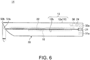
- the electronic apparatus 14 concerned has a configuration that as illustrated in FIG. 6 , the other end part (an open end part 50b) on the opposite side of the first end part (a coupling end part 50a) of the chassis 12 which has been coupled with the apparatus main body 20 via the hinge 24 projects in a state where the position thereof deviates from the position of the other end part (an open end part 51b) on the opposite side of the first end part (a coupling end 51a) on the hinge 24 side of the apparatus main body 20 by a distance L in a direction directing from first end parts toward the other end parts. Accordingly, as illustrated in FIG.
- the plurality of nuts 44 which are the female screw parts is arranged side by side in a direction (in the left-to-right direction in FIG. 2 and FIG. 3 ) along the coupling end parts 50a and 51a of the chassis 12 and the apparatus main body 20 which acts as the other chassis.
- the anchor part 48 is arranged at the position between the two mutually adjacent nuts 44 and 44 so as to fix one hinge 24 (see FIG. 2 and FIG. 3 ).
- the electronic apparatus 14 when the electronic apparatus 14 has fallen in the state of directing the open end parts 50b and 51b downward as the lower ends as described above, it is possible to accept the loads generated on the two nuts 44 and 44 which have fixed one hinge 24 by the anchor part 48 which is arranged between the two nuts in a well-balanced state. Accordingly, the anti-shock property brought about by the anchor part 48 is more improved.
- the anchor parts 48 between the central nut 44 and the left end nut 44 and between the central nut 44 and the right end nut 44.
- one pair of the anchor parts 48 is arranged side by side in the direction (in the top-to-bottom direction in FIG. 2 and FIG. 3 ) directing from the coupling end parts 50a and 51a of the chassis 12 (the lid body 16) and the apparatus main body 20 toward the open end parts 50b and 51b on the opposite side.
- the electronic apparatus 14 has been fallen to the ground and so forth in the state of directing the open end parts 50b and 51b downward as the lower ends, it is possible to accept the loads generated on the two nuts 44 and 44 which have fixed one hinge 24 by the anchor parts 48 which have been arranged side by side in the orthogonal direction between the two nuts 44 and 44 in the more well-balanced state. Accordingly, the anti-shock property brought about by the anchor part 48 is more improved.
- the anchor part 48 is arranged in the state where the position thereof deviates from the position of the nut 44 which is the female screw part in the direction directing from the coupling end parts 50a and 51a toward the open end parts 50b and 51b on the opposite side of the chassis 12 and the apparatus main body 20 (see FIG. 3 ).
- the electronic apparatus 14 has been fallen in the state of directing the open end parts 50b and 51b downward as the lower ends, it is possible to accept the loads generated on the nuts 44 and 44 which have fixed the hinge 24 by the anchor part 48 the position of which deviates from the position of each nut 44 in the falling direction of the electronic apparatus 14 in the well-balanced state. Accordingly, the anti-shock property by the anchor part 48 is more improved.
- FIG. 7 is a plan view enlargedly illustrating the wide part 32a and its vicinity of the rear face cover 12a in a first altered example that the arrangement of the anchor parts 48 has been changed.
- one anchor part 48 may be provided for the adjacent nuts 44 and 44 as illustrated in FIG. 7 .
- the anchor part 48 may be arranged at a position located at the center between the two nuts 44 and 44.
- FIG. 8 is a plan view enlargedly illustrating the wide part 32a and its vicinity of the rear face cover 12a in a second altered example that the installation number of the nuts 44 has been changed.
- a configuration that one nut 44 has been used may be also made as illustrated in FIG. 8 .
- one pair of the anchor parts 48 may be used so as to sandwich the nut 44 between the anchor parts 48.
- a configuration that the anchor parts 48 are arranged side by side in the direction (the top-to-down direction in FIG. 8 ) directing from the coupling end part 50a toward the open end part 50b of the chassis 12 and the nut 44 is arranged between the anchor parts 48 may be made.
- the present invention is not limited to the above-mentioned embodiment and it is possible to freely change the configuration within a range not deviating from the gist of the present invention.
- the member for a chassis 10 may be also used as the front face cover 12b and the apparatus main body 20.
- the member for a chassis 10 it is possible to utilize the member for a chassis 10 as the members of chassis of various electronic apparatuses such as the Laptop PC, the tablet PC, the smartphone and/or the portable phone and so forth.
- the female screw part (the nut 44) which configures the member for a chassis 10 may be utilized for applications other than clamping of the hinge 24 and may be utilized, for example, as the female screw part used when clamping the front face cover 12b to the rear face cover 12a configured by the member for a chassis 10.
- the laminated sheet 30 may have a laminated structure of five or more layers that each intermediate layer 42 has been sandwiched between the respective layers of, for example, the three or more fiber reinforced resin sheets 40 and 41.
- the female screw part may be also formed by performing screw forming directly on the thermoplastic resin which configures the wide part 32a.
Landscapes
- Engineering & Computer Science (AREA)
- Theoretical Computer Science (AREA)
- Computer Hardware Design (AREA)
- Physics & Mathematics (AREA)
- Human Computer Interaction (AREA)
- General Engineering & Computer Science (AREA)
- General Physics & Mathematics (AREA)
- Mechanical Engineering (AREA)
- Chemical & Material Sciences (AREA)
- Composite Materials (AREA)
- Mathematical Physics (AREA)
- Casings For Electric Apparatus (AREA)
Claims (10)
- Element für ein Gehäuse einer zweischaligen elektronischen Vorrichtung, wobei das Element (10) ein thermoplastisches Harz umfasst, das zumindest mit einem Teil einer externen Formendfläche (30a) einer laminierten Schicht (30) verbunden ist, wobei die laminierte Schicht (30) eine Zwischenschicht (42) aufweist, die zwischen einem Paar von faserverstärkten Harzschichten (40, 41) angeordnet ist, wobei das thermoplastische Harz bis zu einer Oberfläche der laminierten Schicht (30) ausgedehnt ist, gekennzeichnet durch
einen Lochteil (46), der in der Oberfläche der laminierten Schicht (30) bereitgestellt ist und der mit dem ausgedehnten thermoplastischen Harz abgedeckt wurde und wobei das Element (10) für ein Gehäuse einen Ankerteil (48) aufweist, der durch Einsetzen des thermoplastischen Harzes in den Lochteil (46) gebildet wurde,
wobei ein weiblicher Schraubenteil (44) in einem Teil des thermoplastischen Harzes bereitgestellt ist, der zu der Oberfläche der laminierten Schicht (30) ausgedehnt wurde,
und wobei eine Mehrzahl der weiblichen Schraubenteile (44) nebeneinander angeordnet ist und der Ankerteil (48) an einer Position zwischen zwei gegenseitig benachbarten weiblichen Schraubenteilen (44) angeordnet ist. - Element für ein Gehäuse nach Anspruch 1, wobei der weibliche Schraubenteil (44) eine Nuss ist, die von einem Nabenteil (49) positioniert und fixiert wurde, der durch Verwendung von thermoplastischem Harz gebildet wurde.
- Element für ein Gehäuse nach Anspruch 1, wobei eine Mehrzahl von Ankerteilen (48) nebeneinander in einer Richtung, die orthogonal zu einer Richtung ist, in der die zwei gegenseitig benachbarten weiblichen Schraubenteile (44) nebeneinander angeordnet sind, angeordnet sind.
- Element für ein Gehäuse nach einem der Ansprüche 1 bis 3, wobei
der Lochteil (46) sich von der Oberfläche der laminierten Schicht (30) erstreckt und die Zwischenschicht (42) erreicht, und
der Ankerteil (48) in die Zwischenschicht (42) eingesetzt ist. - Zweischalige elektronische Vorrichtung, umfassend:ein Gehäuse, umfassend ein Element (10) für ein Gehäuse in Übereinstimmung mit einem der vorherigen Ansprüche.
- Elektronische Vorrichtung nach Anspruch 5, weiter umfassend:ein zweites Gehäuse, das mit dem ersten Gehäuse gekoppelt wurde, um durch ein Scharnier (24) öffenbar und schließbar zu sein, wobei ein Scharnier (24) an die weiblichen Schraubenteile (44) angeschraubt und daran fixiert ist.
- Elektronische Vorrichtung nach Anspruch 6, wobei
eine Mehrzahl von weiblichen Schraubenteilen (44) nebeneinander in einer Richtung entlang von ersten Endteilen des ersten Gehäuses und des zweiten Gehäuses angeordnet sind, die miteinander durch das Scharnier (24) gekoppelt wurden, und
der Ankerteil (48) an einer Position zwischen zwei gegenseitig benachbarten weiblichen Schraubenteilen (44) bereitgestellt ist. - Elektronische Vorrichtung nach Anspruch 6 oder 7, wobei eine Mehrzahl der Ankerteile (48) nebeneinander in einer Richtung, die von ersten Endteilen des ersten Gehäuses und des zweiten Gehäuses, die miteinander durch das Scharnier (24) gekoppelt wurden, zu den gegenüberliegenden zweiten Endteilen des ersten Gehäuses und des zweiten Gehäuses zeigt, angeordnet sind.
- Elektronische Vorrichtung nach Anspruch 6, wobei
der Ankerteil (48) in einem Zustand bereitgestellt ist, wo dessen Position von der Position des weiblichen Schraubenteils (44) in einer Richtung, die von ersten Endteilen des ersten Gehäuses und des zweiten Gehäuses, die miteinander durch das Scharnier (24) gekoppelt wurden, zu den gegenüberliegenden zweiten Endteilen des ersten Gehäuses und des zweiten Gehäuses zeigt, abweicht. - Elektronische Vorrichtung nach einem der Ansprüche 6 bis 9, wobei
an dem ersten Gehäuse der andere Endteil an der gegenüberliegenden Seite des ersten Endteils, an dem das erste Gehäuse mit dem zweiten Gehäuse durch das Scharnier (24) gekoppelt wurde, in einen Zustand hervorsteht, wo dessen Position von der Position des zweiten Endteils des zweiten Gehäuses in eine Richtung, die von den ersten Endteilen zu den zweiten Endteilen des ersten Gehäuses und des zweiten Gehäuses zeigt, abweicht.
Applications Claiming Priority (1)
| Application Number | Priority Date | Filing Date | Title |
|---|---|---|---|
| JP2016087761A JP6125073B1 (ja) | 2016-04-26 | 2016-04-26 | 筐体用部材及び電子機器 |
Publications (2)
| Publication Number | Publication Date |
|---|---|
| EP3239805A1 EP3239805A1 (de) | 2017-11-01 |
| EP3239805B1 true EP3239805B1 (de) | 2018-11-14 |
Family
ID=58644874
Family Applications (1)
| Application Number | Title | Priority Date | Filing Date |
|---|---|---|---|
| EP17167953.3A Active EP3239805B1 (de) | 2016-04-26 | 2017-04-25 | Gehäuseteil für ein elektronisches gerät |
Country Status (9)
| Country | Link |
|---|---|
| US (1) | US10289153B2 (de) |
| EP (1) | EP3239805B1 (de) |
| JP (1) | JP6125073B1 (de) |
| KR (1) | KR102111188B1 (de) |
| CN (1) | CN107390778B (de) |
| BR (1) | BR102017008597B1 (de) |
| DE (1) | DE102017108787A1 (de) |
| GB (1) | GB2550678B (de) |
| TW (1) | TWI645765B (de) |
Families Citing this family (5)
| Publication number | Priority date | Publication date | Assignee | Title |
|---|---|---|---|---|
| JP5976908B1 (ja) * | 2015-09-04 | 2016-08-24 | レノボ・シンガポール・プライベート・リミテッド | 筐体用部材及び電子機器 |
| TWI690419B (zh) * | 2018-11-16 | 2020-04-11 | 可成科技股份有限公司 | 用於無線通訊的複合材料外殼、其製造方法及使用其的無線通訊裝置 |
| JP2020099004A (ja) * | 2018-12-18 | 2020-06-25 | レノボ・シンガポール・プライベート・リミテッド | 電子機器 |
| JP7328509B2 (ja) * | 2019-05-28 | 2023-08-17 | キョーラク株式会社 | 構造体及び構造体の製造方法 |
| JP7531026B1 (ja) | 2023-06-29 | 2024-08-08 | レノボ・シンガポール・プライベート・リミテッド | 電子機器及び筐体部材 |
Family Cites Families (21)
| Publication number | Priority date | Publication date | Assignee | Title |
|---|---|---|---|---|
| JP2000286565A (ja) * | 1999-01-29 | 2000-10-13 | Kobe Steel Ltd | 電子機器用筺体 |
| JP3673223B2 (ja) * | 2002-01-21 | 2005-07-20 | 株式会社東芝 | 携帯用情報機器 |
| KR100918280B1 (ko) * | 2003-02-17 | 2009-09-18 | 엘지디스플레이 주식회사 | 액정표시장치모듈 |
| US20100165466A1 (en) * | 2005-12-01 | 2010-07-01 | Fujifilm Corporation | Optical sheet for display, and manufacturing method and apparatus therefor |
| WO2007064032A1 (en) * | 2005-12-01 | 2007-06-07 | Fujifilm Corporation | Optical sheet for display, and manufacturing method and apparatus therefor |
| CN101207978A (zh) * | 2006-12-21 | 2008-06-25 | 英业达股份有限公司 | 应用于电子设备的壳体结构 |
| JP5051648B2 (ja) * | 2008-01-11 | 2012-10-17 | レノボ・シンガポール・プライベート・リミテッド | 電子機器の筐体構造および電子機器 |
| JP5105361B2 (ja) * | 2008-01-11 | 2012-12-26 | レノボ・シンガポール・プライベート・リミテッド | 電子機器 |
| TWI376185B (en) * | 2008-05-16 | 2012-11-01 | Foxconn Tech Co Ltd | Housing for electronic device and method for manufacturing the same |
| US20100208161A1 (en) * | 2009-02-19 | 2010-08-19 | Victor Company Of Japan, Limited | Backlight device and liquid crystal display |
| CN101951738A (zh) * | 2009-07-10 | 2011-01-19 | 深圳富泰宏精密工业有限公司 | 壳体及其制造方法 |
| KR101179446B1 (ko) * | 2012-04-04 | 2012-09-07 | 주식회사 우전앤한단 | 모바일 기기 |
| JP5627032B2 (ja) | 2012-04-27 | 2014-11-19 | レノボ・シンガポール・プライベート・リミテッド | 筐体用材料、当該筐体用材料の製造方法、当該筐体用材料を用いた電子機器用筐体、当該電子機器用筐体の製造方法、当該電子機器用筐体を用いた電子機器 |
| TWI520669B (zh) * | 2012-05-25 | 2016-02-01 | 緯創資通股份有限公司 | 筆記型電腦的螢幕 |
| CN103917063A (zh) * | 2013-01-07 | 2014-07-09 | 华为终端有限公司 | 电子设备 |
| JP6286945B2 (ja) * | 2013-08-28 | 2018-03-07 | 富士通株式会社 | 外装ケース及び電子機器 |
| JP6155979B2 (ja) * | 2013-08-29 | 2017-07-05 | 富士通株式会社 | 情報処理装置 |
| US9069523B2 (en) * | 2013-09-30 | 2015-06-30 | Google Inc. | Computer display including a bezel |
| WO2015060843A1 (en) * | 2013-10-23 | 2015-04-30 | Aliantrak Developments Llc | Electronic device with composite display housing |
| CN204515597U (zh) * | 2015-02-26 | 2015-07-29 | 联想(北京)有限公司 | 电子设备 |
| JP5976908B1 (ja) * | 2015-09-04 | 2016-08-24 | レノボ・シンガポール・プライベート・リミテッド | 筐体用部材及び電子機器 |
-
2016
- 2016-04-26 JP JP2016087761A patent/JP6125073B1/ja active Active
-
2017
- 2017-03-13 KR KR1020170030955A patent/KR102111188B1/ko active Active
- 2017-03-17 CN CN201710161767.6A patent/CN107390778B/zh active Active
- 2017-03-17 TW TW106108983A patent/TWI645765B/zh active
- 2017-04-25 DE DE102017108787.7A patent/DE102017108787A1/de active Pending
- 2017-04-25 GB GB1706530.1A patent/GB2550678B/en active Active
- 2017-04-25 EP EP17167953.3A patent/EP3239805B1/de active Active
- 2017-04-26 US US15/498,110 patent/US10289153B2/en active Active
- 2017-04-26 BR BR102017008597-0A patent/BR102017008597B1/pt active IP Right Grant
Non-Patent Citations (1)
| Title |
|---|
| None * |
Also Published As
| Publication number | Publication date |
|---|---|
| TW201740783A (zh) | 2017-11-16 |
| CN107390778B (zh) | 2020-06-05 |
| KR20170122110A (ko) | 2017-11-03 |
| KR102111188B1 (ko) | 2020-05-14 |
| JP2017199100A (ja) | 2017-11-02 |
| TWI645765B (zh) | 2018-12-21 |
| GB201706530D0 (en) | 2017-06-07 |
| GB2550678A (en) | 2017-11-29 |
| BR102017008597B1 (pt) | 2022-07-05 |
| JP6125073B1 (ja) | 2017-05-10 |
| GB2550678B (en) | 2020-12-16 |
| BR102017008597A2 (pt) | 2020-09-24 |
| US20170308119A1 (en) | 2017-10-26 |
| US10289153B2 (en) | 2019-05-14 |
| CN107390778A (zh) | 2017-11-24 |
| EP3239805A1 (de) | 2017-11-01 |
| DE102017108787A1 (de) | 2017-10-26 |
Similar Documents
| Publication | Publication Date | Title |
|---|---|---|
| EP3239805B1 (de) | Gehäuseteil für ein elektronisches gerät | |
| KR102110010B1 (ko) | 케이스용 부재 및 전자 기기 | |
| JP6077024B2 (ja) | 筐体用材料、電子機器及び筐体用材料の製造方法 | |
| US10398042B2 (en) | Electronic device with an increased flexural rigidity | |
| JP5986673B1 (ja) | 筐体用部材、電子機器、筐体用部材の製造方法、締結構造体及び締結方法 | |
| US9743166B2 (en) | Device generating sound | |
| JP6077025B2 (ja) | 筐体構造体及び電子機器 | |
| US11388828B2 (en) | Chassis member, electronic device, and method for manufacturing the chassis member | |
| JP2019059105A (ja) | 筐体用部材の製造方法、積層板、筐体用部材及び電子機器 | |
| WO2015159518A1 (ja) | 電子機器及びその筐体の製造方法 | |
| JP2017147537A (ja) | 電子機器および電子機器用筐体 | |
| BR102017016555A2 (pt) | Membro para chassis e aparelho eletrônico | |
| JP6277240B1 (ja) | 電子機器 | |
| JP2017136740A (ja) | 積層板、筐体用部材、電子機器及び筐体用部材の製造方法 |
Legal Events
| Date | Code | Title | Description |
|---|---|---|---|
| STAA | Information on the status of an ep patent application or granted ep patent |
Free format text: STATUS: UNKNOWN |
|
| PUAI | Public reference made under article 153(3) epc to a published international application that has entered the european phase |
Free format text: ORIGINAL CODE: 0009012 |
|
| STAA | Information on the status of an ep patent application or granted ep patent |
Free format text: STATUS: REQUEST FOR EXAMINATION WAS MADE |
|
| STAA | Information on the status of an ep patent application or granted ep patent |
Free format text: STATUS: EXAMINATION IS IN PROGRESS |
|
| 17P | Request for examination filed |
Effective date: 20170425 |
|
| AK | Designated contracting states |
Kind code of ref document: A1 Designated state(s): AL AT BE BG CH CY CZ DE DK EE ES FI FR GB GR HR HU IE IS IT LI LT LU LV MC MK MT NL NO PL PT RO RS SE SI SK SM TR |
|
| AX | Request for extension of the european patent |
Extension state: BA ME |
|
| 17Q | First examination report despatched |
Effective date: 20171024 |
|
| GRAP | Despatch of communication of intention to grant a patent |
Free format text: ORIGINAL CODE: EPIDOSNIGR1 |
|
| STAA | Information on the status of an ep patent application or granted ep patent |
Free format text: STATUS: GRANT OF PATENT IS INTENDED |
|
| INTG | Intention to grant announced |
Effective date: 20180531 |
|
| GRAS | Grant fee paid |
Free format text: ORIGINAL CODE: EPIDOSNIGR3 |
|
| GRAA | (expected) grant |
Free format text: ORIGINAL CODE: 0009210 |
|
| STAA | Information on the status of an ep patent application or granted ep patent |
Free format text: STATUS: THE PATENT HAS BEEN GRANTED |
|
| AK | Designated contracting states |
Kind code of ref document: B1 Designated state(s): AL AT BE BG CH CY CZ DE DK EE ES FI FR GB GR HR HU IE IS IT LI LT LU LV MC MK MT NL NO PL PT RO RS SE SI SK SM TR |
|
| REG | Reference to a national code |
Ref country code: CH Ref legal event code: EP Ref country code: AT Ref legal event code: REF Ref document number: 1065576 Country of ref document: AT Kind code of ref document: T Effective date: 20181115 |
|
| REG | Reference to a national code |
Ref country code: IE Ref legal event code: FG4D |
|
| REG | Reference to a national code |
Ref country code: DE Ref legal event code: R096 Ref document number: 602017000887 Country of ref document: DE |
|
| REG | Reference to a national code |
Ref country code: NL Ref legal event code: FP |
|
| REG | Reference to a national code |
Ref country code: LT Ref legal event code: MG4D |
|
| REG | Reference to a national code |
Ref country code: AT Ref legal event code: MK05 Ref document number: 1065576 Country of ref document: AT Kind code of ref document: T Effective date: 20181114 |
|
| PG25 | Lapsed in a contracting state [announced via postgrant information from national office to epo] |
Ref country code: IS Free format text: LAPSE BECAUSE OF FAILURE TO SUBMIT A TRANSLATION OF THE DESCRIPTION OR TO PAY THE FEE WITHIN THE PRESCRIBED TIME-LIMIT Effective date: 20190314 Ref country code: ES Free format text: LAPSE BECAUSE OF FAILURE TO SUBMIT A TRANSLATION OF THE DESCRIPTION OR TO PAY THE FEE WITHIN THE PRESCRIBED TIME-LIMIT Effective date: 20181114 Ref country code: BG Free format text: LAPSE BECAUSE OF FAILURE TO SUBMIT A TRANSLATION OF THE DESCRIPTION OR TO PAY THE FEE WITHIN THE PRESCRIBED TIME-LIMIT Effective date: 20190214 Ref country code: HR Free format text: LAPSE BECAUSE OF FAILURE TO SUBMIT A TRANSLATION OF THE DESCRIPTION OR TO PAY THE FEE WITHIN THE PRESCRIBED TIME-LIMIT Effective date: 20181114 Ref country code: LT Free format text: LAPSE BECAUSE OF FAILURE TO SUBMIT A TRANSLATION OF THE DESCRIPTION OR TO PAY THE FEE WITHIN THE PRESCRIBED TIME-LIMIT Effective date: 20181114 Ref country code: LV Free format text: LAPSE BECAUSE OF FAILURE TO SUBMIT A TRANSLATION OF THE DESCRIPTION OR TO PAY THE FEE WITHIN THE PRESCRIBED TIME-LIMIT Effective date: 20181114 Ref country code: NO Free format text: LAPSE BECAUSE OF FAILURE TO SUBMIT A TRANSLATION OF THE DESCRIPTION OR TO PAY THE FEE WITHIN THE PRESCRIBED TIME-LIMIT Effective date: 20190214 Ref country code: FI Free format text: LAPSE BECAUSE OF FAILURE TO SUBMIT A TRANSLATION OF THE DESCRIPTION OR TO PAY THE FEE WITHIN THE PRESCRIBED TIME-LIMIT Effective date: 20181114 Ref country code: AT Free format text: LAPSE BECAUSE OF FAILURE TO SUBMIT A TRANSLATION OF THE DESCRIPTION OR TO PAY THE FEE WITHIN THE PRESCRIBED TIME-LIMIT Effective date: 20181114 |
|
| PG25 | Lapsed in a contracting state [announced via postgrant information from national office to epo] |
Ref country code: PT Free format text: LAPSE BECAUSE OF FAILURE TO SUBMIT A TRANSLATION OF THE DESCRIPTION OR TO PAY THE FEE WITHIN THE PRESCRIBED TIME-LIMIT Effective date: 20190314 Ref country code: SE Free format text: LAPSE BECAUSE OF FAILURE TO SUBMIT A TRANSLATION OF THE DESCRIPTION OR TO PAY THE FEE WITHIN THE PRESCRIBED TIME-LIMIT Effective date: 20181114 Ref country code: AL Free format text: LAPSE BECAUSE OF FAILURE TO SUBMIT A TRANSLATION OF THE DESCRIPTION OR TO PAY THE FEE WITHIN THE PRESCRIBED TIME-LIMIT Effective date: 20181114 Ref country code: RS Free format text: LAPSE BECAUSE OF FAILURE TO SUBMIT A TRANSLATION OF THE DESCRIPTION OR TO PAY THE FEE WITHIN THE PRESCRIBED TIME-LIMIT Effective date: 20181114 Ref country code: GR Free format text: LAPSE BECAUSE OF FAILURE TO SUBMIT A TRANSLATION OF THE DESCRIPTION OR TO PAY THE FEE WITHIN THE PRESCRIBED TIME-LIMIT Effective date: 20190215 |
|
| PG25 | Lapsed in a contracting state [announced via postgrant information from national office to epo] |
Ref country code: CZ Free format text: LAPSE BECAUSE OF FAILURE TO SUBMIT A TRANSLATION OF THE DESCRIPTION OR TO PAY THE FEE WITHIN THE PRESCRIBED TIME-LIMIT Effective date: 20181114 Ref country code: IT Free format text: LAPSE BECAUSE OF FAILURE TO SUBMIT A TRANSLATION OF THE DESCRIPTION OR TO PAY THE FEE WITHIN THE PRESCRIBED TIME-LIMIT Effective date: 20181114 Ref country code: DK Free format text: LAPSE BECAUSE OF FAILURE TO SUBMIT A TRANSLATION OF THE DESCRIPTION OR TO PAY THE FEE WITHIN THE PRESCRIBED TIME-LIMIT Effective date: 20181114 Ref country code: PL Free format text: LAPSE BECAUSE OF FAILURE TO SUBMIT A TRANSLATION OF THE DESCRIPTION OR TO PAY THE FEE WITHIN THE PRESCRIBED TIME-LIMIT Effective date: 20181114 |
|
| REG | Reference to a national code |
Ref country code: DE Ref legal event code: R097 Ref document number: 602017000887 Country of ref document: DE |
|
| PG25 | Lapsed in a contracting state [announced via postgrant information from national office to epo] |
Ref country code: SM Free format text: LAPSE BECAUSE OF FAILURE TO SUBMIT A TRANSLATION OF THE DESCRIPTION OR TO PAY THE FEE WITHIN THE PRESCRIBED TIME-LIMIT Effective date: 20181114 Ref country code: SK Free format text: LAPSE BECAUSE OF FAILURE TO SUBMIT A TRANSLATION OF THE DESCRIPTION OR TO PAY THE FEE WITHIN THE PRESCRIBED TIME-LIMIT Effective date: 20181114 Ref country code: RO Free format text: LAPSE BECAUSE OF FAILURE TO SUBMIT A TRANSLATION OF THE DESCRIPTION OR TO PAY THE FEE WITHIN THE PRESCRIBED TIME-LIMIT Effective date: 20181114 Ref country code: EE Free format text: LAPSE BECAUSE OF FAILURE TO SUBMIT A TRANSLATION OF THE DESCRIPTION OR TO PAY THE FEE WITHIN THE PRESCRIBED TIME-LIMIT Effective date: 20181114 |
|
| PLBE | No opposition filed within time limit |
Free format text: ORIGINAL CODE: 0009261 |
|
| STAA | Information on the status of an ep patent application or granted ep patent |
Free format text: STATUS: NO OPPOSITION FILED WITHIN TIME LIMIT |
|
| 26N | No opposition filed |
Effective date: 20190815 |
|
| PG25 | Lapsed in a contracting state [announced via postgrant information from national office to epo] |
Ref country code: SI Free format text: LAPSE BECAUSE OF FAILURE TO SUBMIT A TRANSLATION OF THE DESCRIPTION OR TO PAY THE FEE WITHIN THE PRESCRIBED TIME-LIMIT Effective date: 20181114 |
|
| PG25 | Lapsed in a contracting state [announced via postgrant information from national office to epo] |
Ref country code: LU Free format text: LAPSE BECAUSE OF NON-PAYMENT OF DUE FEES Effective date: 20190425 Ref country code: MC Free format text: LAPSE BECAUSE OF FAILURE TO SUBMIT A TRANSLATION OF THE DESCRIPTION OR TO PAY THE FEE WITHIN THE PRESCRIBED TIME-LIMIT Effective date: 20181114 |
|
| REG | Reference to a national code |
Ref country code: DE Ref legal event code: R082 Ref document number: 602017000887 Country of ref document: DE Representative=s name: SCHWEIGER & PARTNERS, DE Ref country code: DE Ref legal event code: R081 Ref document number: 602017000887 Country of ref document: DE Owner name: LENOVO PC INTERNATIONAL LIMITED, HK Free format text: FORMER OWNER: LENOVO (SINGAPORE) PTE. LTD., SINGAPUR, SG |
|
| PG25 | Lapsed in a contracting state [announced via postgrant information from national office to epo] |
Ref country code: FR Free format text: LAPSE BECAUSE OF NON-PAYMENT OF DUE FEES Effective date: 20190430 |
|
| REG | Reference to a national code |
Ref country code: BE Ref legal event code: PD Owner name: LENOVO PC INTERNATIONAL LIMITED; HK Free format text: DETAILS ASSIGNMENT: CHANGE OF OWNER(S), CESSION; FORMER OWNER NAME: LENOVO (SINGAPORE) PTE. LTD. Effective date: 20191205 |
|
| PG25 | Lapsed in a contracting state [announced via postgrant information from national office to epo] |
Ref country code: TR Free format text: LAPSE BECAUSE OF FAILURE TO SUBMIT A TRANSLATION OF THE DESCRIPTION OR TO PAY THE FEE WITHIN THE PRESCRIBED TIME-LIMIT Effective date: 20181114 |
|
| REG | Reference to a national code |
Ref country code: GB Ref legal event code: 732E Free format text: REGISTERED BETWEEN 20200305 AND 20200311 |
|
| PG25 | Lapsed in a contracting state [announced via postgrant information from national office to epo] |
Ref country code: IE Free format text: LAPSE BECAUSE OF NON-PAYMENT OF DUE FEES Effective date: 20190425 |
|
| REG | Reference to a national code |
Ref country code: CH Ref legal event code: PL |
|
| PG25 | Lapsed in a contracting state [announced via postgrant information from national office to epo] |
Ref country code: CH Free format text: LAPSE BECAUSE OF NON-PAYMENT OF DUE FEES Effective date: 20200430 Ref country code: LI Free format text: LAPSE BECAUSE OF NON-PAYMENT OF DUE FEES Effective date: 20200430 |
|
| PG25 | Lapsed in a contracting state [announced via postgrant information from national office to epo] |
Ref country code: CY Free format text: LAPSE BECAUSE OF FAILURE TO SUBMIT A TRANSLATION OF THE DESCRIPTION OR TO PAY THE FEE WITHIN THE PRESCRIBED TIME-LIMIT Effective date: 20181114 |
|
| PG25 | Lapsed in a contracting state [announced via postgrant information from national office to epo] |
Ref country code: HU Free format text: LAPSE BECAUSE OF FAILURE TO SUBMIT A TRANSLATION OF THE DESCRIPTION OR TO PAY THE FEE WITHIN THE PRESCRIBED TIME-LIMIT; INVALID AB INITIO Effective date: 20170425 Ref country code: MT Free format text: LAPSE BECAUSE OF FAILURE TO SUBMIT A TRANSLATION OF THE DESCRIPTION OR TO PAY THE FEE WITHIN THE PRESCRIBED TIME-LIMIT Effective date: 20181114 |
|
| PG25 | Lapsed in a contracting state [announced via postgrant information from national office to epo] |
Ref country code: MK Free format text: LAPSE BECAUSE OF FAILURE TO SUBMIT A TRANSLATION OF THE DESCRIPTION OR TO PAY THE FEE WITHIN THE PRESCRIBED TIME-LIMIT Effective date: 20181114 |
|
| REG | Reference to a national code |
Ref country code: DE Ref legal event code: R082 Ref document number: 602017000887 Country of ref document: DE Representative=s name: SCHWEIGER, MARTIN, DIPL.-ING. UNIV., DE |
|
| P01 | Opt-out of the competence of the unified patent court (upc) registered |
Effective date: 20230627 |
|
| PGFP | Annual fee paid to national office [announced via postgrant information from national office to epo] |
Ref country code: NL Payment date: 20250424 Year of fee payment: 9 |
|
| REG | Reference to a national code |
Ref country code: GB Ref legal event code: 732E Free format text: REGISTERED BETWEEN 20250508 AND 20250514 |
|
| REG | Reference to a national code |
Ref country code: DE Ref legal event code: R081 Ref document number: 602017000887 Country of ref document: DE Owner name: LENOVO SWITZERLAND INTERNATIONAL GMBH, CH Free format text: FORMER OWNER: LENOVO PC INTERNATIONAL LIMITED, QUARRY BAY, HK |
|
| PGFP | Annual fee paid to national office [announced via postgrant information from national office to epo] |
Ref country code: DE Payment date: 20250428 Year of fee payment: 9 |
|
| REG | Reference to a national code |
Ref country code: NL Ref legal event code: PD Owner name: LENOVO SWITZERLAND INTERNATIONAL GMBH; CH Free format text: DETAILS ASSIGNMENT: CHANGE OF OWNER(S), ASSIGNMENT; FORMER OWNER NAME: LENOVO (SINGAPORE) PTE. LTD. Effective date: 20250630 |
|
| PGFP | Annual fee paid to national office [announced via postgrant information from national office to epo] |
Ref country code: GB Payment date: 20250422 Year of fee payment: 9 |
|
| PGFP | Annual fee paid to national office [announced via postgrant information from national office to epo] |
Ref country code: BE Payment date: 20250424 Year of fee payment: 9 |
|
| REG | Reference to a national code |
Ref country code: BE Ref legal event code: PD Owner name: LENOVO SWITZERLAND INTERNATIONAL GMBH; CH Free format text: DETAILS ASSIGNMENT: CHANGE OF OWNER(S), ASSIGNMENT; FORMER OWNER NAME: LENOVO PC INTERNATIONAL LIMITED Effective date: 20250612 |