EP3235668A1 - Superstructure bâchée - Google Patents
Superstructure bâchée Download PDFInfo
- Publication number
- EP3235668A1 EP3235668A1 EP17165373.6A EP17165373A EP3235668A1 EP 3235668 A1 EP3235668 A1 EP 3235668A1 EP 17165373 A EP17165373 A EP 17165373A EP 3235668 A1 EP3235668 A1 EP 3235668A1
- Authority
- EP
- European Patent Office
- Prior art keywords
- tarpaulin
- latch
- locking
- guide
- bracket
- Prior art date
- Legal status (The legal status is an assumption and is not a legal conclusion. Google has not performed a legal analysis and makes no representation as to the accuracy of the status listed.)
- Granted
Links
Images


Classifications
-
- B—PERFORMING OPERATIONS; TRANSPORTING
- B60—VEHICLES IN GENERAL
- B60J—WINDOWS, WINDSCREENS, NON-FIXED ROOFS, DOORS, OR SIMILAR DEVICES FOR VEHICLES; REMOVABLE EXTERNAL PROTECTIVE COVERINGS SPECIALLY ADAPTED FOR VEHICLES
- B60J7/00—Non-fixed roofs; Roofs with movable panels, e.g. rotary sunroofs
- B60J7/02—Non-fixed roofs; Roofs with movable panels, e.g. rotary sunroofs of sliding type, e.g. comprising guide shoes
- B60J7/06—Non-fixed roofs; Roofs with movable panels, e.g. rotary sunroofs of sliding type, e.g. comprising guide shoes with non-rigid element or elements
- B60J7/061—Non-fixed roofs; Roofs with movable panels, e.g. rotary sunroofs of sliding type, e.g. comprising guide shoes with non-rigid element or elements sliding and folding
- B60J7/062—Non-fixed roofs; Roofs with movable panels, e.g. rotary sunroofs of sliding type, e.g. comprising guide shoes with non-rigid element or elements sliding and folding for utility vehicles
-
- B—PERFORMING OPERATIONS; TRANSPORTING
- B60—VEHICLES IN GENERAL
- B60J—WINDOWS, WINDSCREENS, NON-FIXED ROOFS, DOORS, OR SIMILAR DEVICES FOR VEHICLES; REMOVABLE EXTERNAL PROTECTIVE COVERINGS SPECIALLY ADAPTED FOR VEHICLES
- B60J7/00—Non-fixed roofs; Roofs with movable panels, e.g. rotary sunroofs
- B60J7/02—Non-fixed roofs; Roofs with movable panels, e.g. rotary sunroofs of sliding type, e.g. comprising guide shoes
- B60J7/06—Non-fixed roofs; Roofs with movable panels, e.g. rotary sunroofs of sliding type, e.g. comprising guide shoes with non-rigid element or elements
- B60J7/061—Non-fixed roofs; Roofs with movable panels, e.g. rotary sunroofs of sliding type, e.g. comprising guide shoes with non-rigid element or elements sliding and folding
- B60J7/064—Non-fixed roofs; Roofs with movable panels, e.g. rotary sunroofs of sliding type, e.g. comprising guide shoes with non-rigid element or elements sliding and folding using folding arms sliding in longitudinal tracks for supporting the soft roof
- B60J7/065—Non-fixed roofs; Roofs with movable panels, e.g. rotary sunroofs of sliding type, e.g. comprising guide shoes with non-rigid element or elements sliding and folding using folding arms sliding in longitudinal tracks for supporting the soft roof for utility vehicles
-
- B—PERFORMING OPERATIONS; TRANSPORTING
- B60—VEHICLES IN GENERAL
- B60J—WINDOWS, WINDSCREENS, NON-FIXED ROOFS, DOORS, OR SIMILAR DEVICES FOR VEHICLES; REMOVABLE EXTERNAL PROTECTIVE COVERINGS SPECIALLY ADAPTED FOR VEHICLES
- B60J7/00—Non-fixed roofs; Roofs with movable panels, e.g. rotary sunroofs
- B60J7/08—Non-fixed roofs; Roofs with movable panels, e.g. rotary sunroofs of non-sliding type, i.e. movable or removable roofs or panels, e.g. let-down tops or roofs capable of being easily detached or of assuming a collapsed or inoperative position
- B60J7/10—Non-fixed roofs; Roofs with movable panels, e.g. rotary sunroofs of non-sliding type, i.e. movable or removable roofs or panels, e.g. let-down tops or roofs capable of being easily detached or of assuming a collapsed or inoperative position readily detachable, e.g. tarpaulins with frames, or fastenings for tarpaulins
- B60J7/102—Readily detachable tarpaulins, e.g. for utility vehicles; Frames therefor
-
- B—PERFORMING OPERATIONS; TRANSPORTING
- B60—VEHICLES IN GENERAL
- B60J—WINDOWS, WINDSCREENS, NON-FIXED ROOFS, DOORS, OR SIMILAR DEVICES FOR VEHICLES; REMOVABLE EXTERNAL PROTECTIVE COVERINGS SPECIALLY ADAPTED FOR VEHICLES
- B60J7/00—Non-fixed roofs; Roofs with movable panels, e.g. rotary sunroofs
- B60J7/185—Locking arrangements
- B60J7/1856—Locking arrangements for interlocking the roof linkage system when deployed
-
- B—PERFORMING OPERATIONS; TRANSPORTING
- B61—RAILWAYS
- B61D—BODY DETAILS OR KINDS OF RAILWAY VEHICLES
- B61D39/00—Wagon or like covers; Tarpaulins; Movable or foldable roofs
- B61D39/002—Sliding or folding roofs
-
- B—PERFORMING OPERATIONS; TRANSPORTING
- B60—VEHICLES IN GENERAL
- B60Y—INDEXING SCHEME RELATING TO ASPECTS CROSS-CUTTING VEHICLE TECHNOLOGY
- B60Y2200/00—Type of vehicle
- B60Y2200/10—Road Vehicles
- B60Y2200/14—Trucks; Load vehicles, Busses
-
- B—PERFORMING OPERATIONS; TRANSPORTING
- B60—VEHICLES IN GENERAL
- B60Y—INDEXING SCHEME RELATING TO ASPECTS CROSS-CUTTING VEHICLE TECHNOLOGY
- B60Y2200/00—Type of vehicle
- B60Y2200/10—Road Vehicles
- B60Y2200/14—Trucks; Load vehicles, Busses
- B60Y2200/147—Trailers, e.g. full trailers or caravans
-
- B—PERFORMING OPERATIONS; TRANSPORTING
- B60—VEHICLES IN GENERAL
- B60Y—INDEXING SCHEME RELATING TO ASPECTS CROSS-CUTTING VEHICLE TECHNOLOGY
- B60Y2200/00—Type of vehicle
- B60Y2200/10—Road Vehicles
- B60Y2200/14—Trucks; Load vehicles, Busses
- B60Y2200/148—Semi-trailers, articulated vehicles
-
- B—PERFORMING OPERATIONS; TRANSPORTING
- B60—VEHICLES IN GENERAL
- B60Y—INDEXING SCHEME RELATING TO ASPECTS CROSS-CUTTING VEHICLE TECHNOLOGY
- B60Y2200/00—Type of vehicle
- B60Y2200/30—Railway vehicles
- B60Y2200/33—Rail cars; Waggons
Definitions
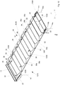
- the invention relates to a tarpaulin structure for a substructure, such as a truck, trailer, semi-trailer, railroad car, dump truck or container, comprising a top frame and a tarpaulin made of weather-resistant material, wherein the roof frame comprises a plurality of bars, the end each having a carriage which along a guide is displaced.
- Such tarpaulin structures are known in the practice to release openable roofs, which are usually the bracket of a pair of hingedly connected to the opposite slide rods, which in turn have a joint at their opposite ends of the slide, in which another rod pivotally mounted is.
- a disadvantage of the known tarpaulin structures is the fact that the brackets have a relatively large angle to the horizontal, which facilitates the displacement in the vertical direction for lifting the tarpaulin, but which practically does not favor the transmission of forces in the direction of displacement. As a result, it is easy to tilt the interconnected via spars carriage, which leads to a blockage of the top frame.
- the spar which rigidly connects the opposing carriages together, is often made very solid, which in turn has the disadvantage that the tolerances of the guide have to go virtually to zero, so that the top frame can be moved.
- Another disadvantage is that the interconnected bracket in the region of their connection allow mutual relative movement in the direction of the guide, in the vertical direction and also in the transverse direction perpendicular thereto, whereby forces and moments that are unilaterally introduced into a carriage, practically not can be transmitted via the bracket in the adjacent slide.
- This has the consequence that the top frames of the known tarpaulin structures always require a symmetrical introduction of the displacement force, so that, for example, the displacement force must be initiated centrally, but usually must be initiated in the same way on both sides.
- Another disadvantage of the known arrangement is that they can be pushed together under folding of the tarpaulin only in a region of the substructure, which still covers the loading opening of the substructure, whereby the loading opening is not fully released. This is particularly disadvantageous in railway cars, as this part of the cargo space is lost.
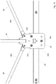
- a tarpaulin structure for a substructure comprising a top frame and a tarpaulin made of weather-resistant material, wherein the top frame comprises a plurality of spars, the ends each having a carriage which is displaceable along a guide.
- At each pair of opposing carriages at least one bracket is pivotally connected, which forms with a bracket of an adjacent pair of carriages a tarpaulin folding aid, wherein the brackets of the tarpaulin folding aid are interconnected.
- the connected bracket on a Schwenkwinkelbe dictionaryr, which allows only a limited pivoting of the bracket, so that the bracket when moving the carriage in the direction of an open position can not overturn.
- US 2007 006 35 30 A1 describes a tarpaulin structure for a substructure, with a roof frame and with a tarpaulin of weather-resistant material, wherein the roof frame has a plurality of bars, the end each having a carriage which is displaceable along a guide.
- each a bracket is pivotally connected to the spar near the carriage, wherein the bracket with a bracket of an adjacent spar forms a tarpaulin folding aid.
- the adjacent stirrups in the region of the bracket portions facing away from the carriage are each non-rotatably connected to a cantilever such that the facing arms of the mutually facing stirrups in a single joint formed by a cylindrical pin extending substantially across the width of the top frame is, are connected such that with the top frame closed the pin protrudes above the upper portions of the spars and so raises the tarpaulin and prevents it from sinking into the areas between the facing brackets.
- the disadvantage here is, on the one hand, that the tarpaulin can not then be arranged without play in the area of the carriages, since the tarpaulin must be able to follow the lifting movement of the lifting yokes.
- a further disadvantage is that the rigid boom are not able to compensate for differences in length of the top frame, but rather can be used only in very specific dimensions due to their angular position with respect to the bracket carrying them.
- US 7 325 855 B2 describes a tarpaulin structure for a semi-trailer, in which a top frame carries a tarpaulin made of weather-resistant material, wherein the top frame comprises a plurality of U-shaped bars, the end each having a carriage which is displaceable along a guide.
- both sides of the spars are hinged once in the area of the carriage and once about halfway up the spar bracket, the upper bracket can be biased by a spring arrangement in an operating direction, while the lower bracket are connected to each other in the region of the side wall of a coupling link , which carries a U-shaped Hubholm, which extends across the width of the top frame.
- this tarpaulin structure allows only certain dimensions, which are designed as a multiple of the distance of the spars, because the interconnected bracket can not be flexibly dimensioned.
- EP 0 955 196 A1 describes a tarpaulin structure for a railroad car, in which a tarpaulin of weather-resistant material is supported by a top frame, the top frame having a plurality of U-shaped bars, the end each having a carriage which is displaceable along a provided in the cargo area guide , At the spars on both sides in each case a handlebar is connected, wherein the mutually facing links of the adjacent spars are hingedly connected to each other and with a cylindrical, vertically oriented guide sleeve, in which a U-shaped Hubholm is taken vertically displaceable, which in moving together of the adjacent spars the pivoting of the handlebars is lifted upwards.
- a disadvantage of the tarpaulin structure is that the spars must be arranged very close to each other, so that an overall very large roof frame with relatively high weight and quite small release opening results from this.
- DE 10 2013 201 006 A1 discloses a tarpaulin type tarpaulin structure for a truck in which a substantially flat tarpaulin of weather-resistant material is connected to a roof frame to allow opening and closing of the roof.
- the top frame has a plurality of trained as an elongated bow beams, which can be raised in each case between the adjacent carriages, designed in the manner of a handlebar lifting elements can be raised.
- the carriages are displaceable along a roof rail forming a guide, with a gantry beam pivotally connected to the foremost pair of carriages, the tarpaulin also being connected to the gantry beam.
- the portal beam extending transversely to the opening direction is connected to the frontmost carriage on both sides by a kinematics designed as a four-bar linkage, wherein the foremost carriage additionally has two spars spanning the roof opening and designed as a bow, wherein the links of the four-bar linkage are at least partially in a substantially below, at least but at the height of the guide arranged recess of the foremost sleigh rest when the gantry beam is lowered.
- the tarpaulin structure has a locking arrangement, with a guided in a front slide first latch member and guided in the opposite frontmost slide second latch member, which are stretched by a respective spring in the locking direction and axially displaceable by actuation in their respective unlocking.
- each bolt is connected to a rope associated with it with an actuating device on the opposite side, wherein the two ropes are adjacent to each other in the area between two bars without being guided on the spars.
- the two cables are coupled together in the center of the tarpaulin structure, so that a one-sided actuation actuates both latch members.
- the disadvantage of this, however, is that transported goods can catch on the ropes and there may be an unintentional opening of the roof.
- FR 2 653 478 A1 describes a tarpaulin structure for a semi-trailer, in which a roof frame is arranged in the roof area, to which a tarpaulin made of weather-resistant material is connected, and which allows opening and closing of the roof.
- the roof frame has a plurality of elongated beams designed as spars, which each end have a carriage which is displaceable along a guide formed by a pair of longitudinal members.
- each Hubheber is arranged, which is non-rotatably coupled with an articulated connected to a carriage elongate arm, so that a tarpaulin help results, the pivoting movement of the one about the carriage pivoting bracket forming, elongated arm together with the Hubspriegel results, wherein the bracket is connected by means of a knee joint of two part core with the adjacent carriage.
- the well-known sunroof further comprises an end-side Abdeckbügel, which is similar to the Hubspriegel formed and is pivotally connected to the frontmost pair of carriages.
- a plate-shaped latch bolt is arranged, which cooperates with down pivoting in the region of the openable end of the longitudinal member with a pin connected to the longitudinal member to the Roof top frame to lock.
- the plate body rests in the closed state of the tarpaulin structure partially on a horizontal portion of the carriage, while a biasing means biases the cover bracket in the opening direction.
- the direction of action of the spring with respect to its articulation on the Abdeckbügel such that an over-center interlock occurs, which must be overcome by vertical bumping the Abdeckbügels.
- the top frame is actuated by a crank.
- a particular disadvantage is the Aufstellkinematik by the pivoting Hubspriegel.
- DE 10 2012 006 385 A1 describes a tarpaulin structure for a commercial vehicle, in which a tarpaulin made of weather-resistant material is connected to a sunroof-forming hood frame, wherein the roof frame comprises a plurality of running in the roof plane, designed as elongated braces Holmen having each end a slide which along a guide formed by a longitudinal member is displaceable. At the foremost (rearmost in the direction of travel) Holm a likewise displaceable along the guide gantry is connected, wherein in the region of one of the two carriages of the foremost spar a locking arrangement is provided which locks the carriage relative to the guide formed by the longitudinal beam, wherein by unilateral pulling on a loop, the locking arrangement can be unlocked.
- the locking assembly is provided only on one side of the foremost spar and can not easily lock the top frame on both side rails.
- the locking arrangement comprises a first locking member and a second locking member, which are arranged on the same longitudinal side of the tarpaulin structure and which are simultaneously displaceable in an unlocking direction by actuation of the pull tab.
- a disadvantage of the tarpaulin structure is in particular the fact that a common unlocking each locking arrangement on both sides of the tarpaulin structure by operation from the outside by an operator is not possible.
- WO 2007 056 989 A2 describes a tarpaulin structure with a top frame, which is provided for supporting a tarpaulin, in which the top frame comprises a plurality of elongated braces designed as spars, which are displaceable on a slide along a guide formed as a longitudinal member in the roof area, wherein at the frontmost slide a locking member is pivotally connected to a slotted guide, which cooperates with a second, connected to the longitudinal member locking member, such that when pulling the tarpaulin in the closing direction, the lock is released.
- EP 0 778 169 B1 describes a tarpaulin structure for the roof region of a truck, in which a top frame carries a tarpaulin made of weather-resistant material, wherein the roof frame comprises a plurality of elongated beams designed as spars, the end each having a carriage which is displaceable along a guide formed by two side members , The adjacent bows are hingedly coupled with these associated Faltplattencrue, wherein each of the two folding plates is hinged together by a continuous Hubspriegel.
- a cover bar realized as a portal bar is hingedly connected, which is acted upon in a direction of movement of a cylinder, wherein in the region of the leg of the Abdeckbügels a hook is provided on both sides, which is pivoted by a pin with an end facing away from the hook, the Hook part engages with another pin for a positive engagement.
- another pin is provided, which is encompassed by a pivotally connected to the side member pivot hooks to secure the gantry bar against lifting. If the top frame is to be opened, the interior must first be entered and the swivel hook must be freely swung out before the cover bracket can be raised.
- a tarpaulin construction for a dump truck in which a tarpaulin made of weather-resistant material can be opened and closed again via a top frame from the dump body to release an opening.
- the top frame has a plurality of U-shaped bars, which are each connected at the end to a guide element, wherein the guide elements are coupled to a drivable operating cable.
- a Abdeckbügel which rests substantially flat on the dump body in the closed state of the tarpaulin structure, is rotatable about a pivot axis, wherein a pin arranged on the substructure pivots an extension of the Abdeckbügels from an erected position to a lowered position and vice versa.
- a spring which loads the Abdeckbügel in the opening direction, stretched as long as the extension rests on the pin.
- the spring causes the cover bracket to swing open without the intervention of an operator.
- a tarpaulin structure for a substructure such as a truck, trailer, semi-trailer, railroad car, dump truck or container, comprising a top frame and a tarpaulin of weather-resistant material, the top frame having a plurality of spars each end one Have carriage which is displaceable along a guide.
- at least one bracket is pivotally mounted either on a pair of opposing carriages of Holmes or connected to the spar, wherein the bracket forms with a bracket of a neighboring Holmes or pair of opposing carriages or a fixed part of the top frame a tarpaulin folding aid with which the tarpaulin can be folded when pushing the top frame in wrinkles.
- the tarpaulin structure is characterized in that the adjacent brackets are coupled to one another via a linkage mechanism, which is collapsible when the convertible top frame moves together.
- the tarpaulin structure with the top frame open, in which the substructure is thus released has an overall lower overall height, since the brackets can be arranged at a comparatively small angle to the spars.
- the steering kinematics assist in that a force introduced into the top frame causes the linkage kinematics to collapse. The thus achieved extension of the effective bracket is not charged to the height of the tarpaulin structure, but achieved by folding the handlebar kinematics a particularly favorable packing density.
- a particular advantage of the tarpaulin structure according to the invention can be seen in that the tarpaulin structure can be adapted much more flexibly to length requirements of the substructure.
- the provision of a linkage kinematics makes it possible to adapt to the distance between adjacent carriages the length of the links or at least one link shorter or longer to choose.
- the angle of attack of the handlebars can be set differently in order to achieve a corresponding length compensation.
- the handlebar kinematics during collapsing of the top frame is collapsible down, so that the displacement movement of the parts of the linkage kinematics essentially has a vertically downward component. This is superimposed by further movements due to the articulated joints of the parts of the handlebar kinematics.
- the linkage kinematics can be connected quite far above the mutually facing brackets, where they are already quite close, so that the handlebar kinematics occupy a total of only a small space.
- this provides a fairly large area below the connection to the brackets, in which the handlebar kinematics can escape.
- the downward movement is not absolute, because the linkage of the linkage kinematics is shifted upwards on the brackets by their pivoting when opening the tarpaulin structure.
- the collapsing movement of the linkage kinematics does not necessarily take place exclusively downwards, but it is sufficient if a downward component is included or is predominantly given.
- the handlebar kinematics can also lead to a spatial movement, for example to such a, in which the tarpaulin is pressed a little way to the outside, to pinching the tarp between the parts of the top frame, in particular between adjacent brackets or between the bracket and spar avoid.
- the linkage kinematics on a knee joint wherein the knee of the knee joint is preferably provided at least approximately and more preferably completely centered, wherein the knee when moving the top frame and thus folding the Lenkerkinematik is advantageously shifted down.
- the knee joint is a particularly simple linkage kinematics, which requires only three points of articulation, and over which a connection of the mutually facing bracket can be achieved.
- a particular advantage of the knee joint is that due to the small play of the pivot pin in the joint eye, the top frame has little tendency to shift due to environmental influences during transport. Furthermore, shear forces can be transferred a bit far.
- the knee joint next to the pivotable in a joint eye pivot pin also has a slot-like hinge eye, whereby a certain axial guide of the pivot pin is given in the slot-like hinge eye in the manner of a slide track.
- the force acting in the direction of displacement of the top frame then leads to a displacement of the pivot point in the region of the knee, whereby the displacement of the knee is achieved with higher reliability.
- a handlebar kinematics comes into consideration, which is designed as a scissors joint, or a handlebar kinematics, which is designed as a multi-joint, in particular as a four-bar linkage.
- the more asymmetrical Mehrgelenkkinematik has a higher number of parts, but is more specific in their movement.
- a multi-knee steering linkage is also considered.
- the handlebars of the handlebar kinematics can be designed both as a rigid lever-like arm as well as plastic parts or as wire components, as long as a defined pivoting of the links with respect to each other and preferably also with respect to the bracket to which they are attached given.
- one of the links is designed with one step so that it can swing past the other link.
- the step also forms a stop for the other link, which limits the minimum angle between the two links. It is possible to limit the maximum pivoting angle with a stop, for example on the links in the region of the joint joint.
- the linkage kinematics on a first link and a second link wherein each of the first link and second link is connected in each case to one of the two adjacent bracket, wherein the first link and the second link are connected to each other via a hinge.
- the joint then forms the knee of a knee joint of the first link and the second link, wherein the first link and the second link are both collapsible on the common joint and via the joints, with which they are respectively connected to the brackets, a pivoting with respect to the stirrups.
- the pivoting angle of the handlebars on the bracket e.g. to limit by a stop and / or limit the pivot angle of the joint joint of the first link and the second link, so that an unintentional pivoting outside of the knee joint intended pivoting range is avoided.
- the mass of the first link and the second link cause the joint joint to move substantially downwards.
- the pivoting angle of the joint joint can be realized for example by an elongatable connecting strut, which is connected to the first link and the second link at a distance from the common joint, which limits the maximum opening angle of the first link relative to the second link.
- the connecting strut is particularly advantageous when the movable part of the top frame is moved starting from the open position to the closed position, since this prevents the first link and the second link a straight extension, ie at an angle of 180 ° , assume that would mean a dead center position, in which the risk of evading the knee would be in the wrong direction.
- the first link and the second link expediently enclose an angle between 90 ° and 180 °, wherein preferably the included angle between 120 ° and 170 ° and particularly preferably includes between 150 ° and 165 °.
- the angle smaller than 180 ° and pointing down the folding of the handlebar kinematics is favored down.
- the brackets are expediently U-shaped with a base and two legs, each of the legs is connected to a carriage or on a leg of the spar, wherein the first link and / or the second link is connected in each case articulated on one of the legs.
- the swiveling in the direction of the spar when opening the convertible top frame then create space for the collapsed linkage kinematics and their handlebars.
- the two adjacent brackets are spaced from each other, so that the plane folding aid formed by the two brackets additionally comprises at least one linkage kinematics.
- a steering kinematics preferably in the form of a knee joint, be provided on both sides, so that a force acting in the opening or closing direction force evenly from a pair connected by a spar carriage on the bracket and the linkage kinematics on the adjacent pair of a sled connected carriage is transmitted and there is no tilting.
- the linkage kinematics is arranged in a region of the stirrups which lies outside a load receiving space of the substructure.
- a tarpaulin structure in which all pairs of adjacent stirrups are interconnected by at least one linkage kinematics and preferably by two linkage kinematics, which are preferably mirror images of each other, so that no spaces are created between adjacent links and / or links in which the linkage the parts of the top frame are exclusively on the tarpaulin.
- brackets or only selected pairs of brackets on the linkage kinematics be connected to each other, while other pairs of brackets are either not connected at all or if necessary.
- a buckle, a belt or the like are tied together.
- the inclination, ie the tendency, of the linkage kinematics for folding by a mechanical holding arrangement is adjustable.
- a mechanical holding arrangement may be, for example, a joint brake of the joint joint, a provided between the links of the handlebar kinematics spring member or damping element, an attacking on the brackets or the links or the bars tension belt or the like and makes it possible in particular, that the order in which the adjacent spars merge can be controlled.
- a comparable mechanical holding arrangement can also be provided between brackets and carriages and / or spar.
- this achieves the result that the areas of the convertible top frame lying in the opening direction fold first, and only toward the end of the opening process are the front segments folded. According to an alternative embodiment, only the front segments drive together, and finally the rear ones. In particular, this avoids that the collision of segments of the tarpaulin structure is essentially random, whereby the moving masses and the forces required for this purpose can vary greatly. Furthermore, the mechanical support structure, if it contains an energy storage, also provide assistance in opening or closing the top frame.
- the spars are U-shaped, wherein a base of the U-shaped spars, which is turned away from the carriage, is arranged in the closed state of the tarpaulin structure at approximately the same height as the carriage remote areas of the bracket, in particular its base.
- the linkage kinematics is located slightly below the level of the base of the stirrup, so that the linkage kinematics can not interact with the roof area of the tarpaulin.
- the handlebar kinematics is quite high up on the brackets connected to provide the largest possible Abtauch Scheme down ready, in which the parts of the handlebar kinematics do not come into contact with the guide and / or the carriage, resulting in unpleasant noise, but also can lead to wear.
- a tarpaulin structure for a substructure such as a truck, trailer, semi-trailer, railroad car, dump truck or container, comprising a top frame and a tarpaulin of weather-resistant material, the top frame having a plurality of spars each end one Have carriage, the carriage along a guide is displaced.
- At least one bracket is pivotally connected optionally to a pair of opposed carriages of the spar or to the spar, wherein the bracket with a bracket of a neighboring Holmes or pair of opposing carriages or a fixed part of the top frame forms a tarpaulin.
- the tarpaulin folding aid can also contain a handlebar kinematics connecting the adjacent brackets as described above.
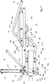
- a Abdeckbügel is pivotally connected to the frontmost pair of carriages, which can cover the front part of the substructure.
- the foremost carriage on a frame portion which is disposed above the guide in a horizontal plane, wherein the frame portion forms a support for the Abdeckbügel in its lowered-down state.
- the support for the cover bracket along the guide can be moved without the cover bracket rests on the base and must form a conclusion with this.
- the coordinated supports and cover bars allow a much denser completion, so that transported goods can escape harder.
- the cover bracket is hinged to the frame portion, which in turn can form a structural unit with the frontmost pair of carriages, so that the cover bracket can be made quite short overall.
- a particular advantage is that even with lowered Abdeckbügel the movable part of the tarpaulin structure along the guide can be moved, or the Abdeckbügel can be swung down again, even if the Top frame is not completely closed, so that when the cover is swung down before reaching the end position, the relocation can be continued.
- the cover bow has a support region which is arranged on the carriage outside its articulation and which comes to rest horizontally on the frame section.
- the cover bracket it is advantageously possible for the cover bracket to be adapted to the course of the tarpaulin to be struck by it, while the support area comes to rest on the support when the cover stirrup is pivoted downwards.
- the support region may be formed integrally with the cover bracket, but it is preferably a strut which is connected to the Abdeckbügel.
- the Abdeckbügel preferably has an angle-shaped leg, so that the Abdeckbügel has a three-dimensional extent.
- the angular leg on a short leg portion which is articulated hinged to the foremost carriage, and further, the angle-shaped leg has a long leg portion facing the short leg portion over a leg angle of about 90 ° and 145 ° and preferably bent about 120 °.
- the support portion then connects the short leg portion and the long leg portion to a portion that is turned away from the leg angle such that the support portion lies approximately in a horizontal plane with the base of the cover bracket.
- the cover is particularly robust and designed with a triangle executed in the manner of a triangle and can pivot about its articulation without twisting, and at the same time keep the tarpaulin in shape by its angular legs.
- the cover bracket comes to rest in its open state with the short leg portion on the frame portion horizontally.
- the cover bracket on two stable, held by the mass of the Abdeckbügels in position states, which are both supported on the frame portion, wherein in the swung-down state of the support region and in the swung-open state of the short leg portion is supported respectively on the frame portion.
- the frontmost slide can be displaced along the guide both with the cover cover open and with the cover cover swiveled down, without the cover clip introducing any resistance to the displacement in the system.
- the articulation of the Abdeckbügels is arranged in a horizontal plane above a plane of articulation of the bracket.
- the cover bracket is pivotally connected to the frame portion, and further that at least one support roller and at least one counter-roller is connected to the frame portion. In this way, it is advantageously achieved that the cover bracket can be pivoted about its articulation without a link mechanism.
- the cover extends beyond the frame portion in the opening direction at least a little way, whereby the guide, along which the foremost carriages and the frame sections are displaced, can be made somewhat shorter. In this way, a lock between the cover bracket and the frame portion can be provided closer to the articulation of the Abdeckbügels on the frame portion.
- the Abdeckbügel is formed in the region of its lateral limbs in the manner of a truss, which ensures a high rigidity and thereby also the two foremost carriage mutually additionally stiffened.
- a lower horizontal strut of the truss or the lateral leg rests on the frame portion at least partially, so that in case of movement of the foremost carriage with the frame portion and the Abdeckbügel is moved accordingly.
- the actuating link is formed as an extension of the lateral leg of the Abdeckbügels and thus allows a backlash-free swinging the Abdeckbügels without intermediate link mechanism and without the associated bearing clearance in the associated joints.
- a tarpaulin structure for a substructure such as a truck, trailer, semi-trailer, railroad car, dump truck or container, comprising a top frame and a tarpaulin of weather-resistant material, the top frame having a plurality of spars each end one Have carriage which is displaceable along a guide.
- At least one bracket is pivotally connected optionally to a pair of opposing carriages of the spar or to the spar, wherein the bracket with a bracket of an adjacent spar or pair of opposing carriages or a fixed part of the top frame forms a tarpaulin folding aid containing a handlebar kinematics as described above may, but does not have to, if, for example, the tarpaulin-folding aid is accomplished by interconnected brackets.
- At the foremost pair of carriages here is a Abdeckbügel pivotally connected, wherein an auxiliary bracket is pivotally connected to the foremost carriage between the Abdeckbügel and connected to the foremost sled Holm.
- the spar stretches the Auxiliary bracket from the one front slide of the pair of front slide to the opposite other foremost slide.
- the auxiliary bracket is in its angular position and its extent, so substantially height, selected so that it supports the tarp in a region between the cover bracket and the spar.
- the auxiliary bow is suitably arranged so that it does not stand in the way of pivoting the Abdeckbügels.
- a biasing member is arranged between the preferably U-shaped auxiliary bracket and the cover bracket, which biases the Abdeckbügel against its closing direction.
- the biasing member can cause that upon unlocking the Abdeckbügels this is raised against its closing direction.
- the biasing member can cause the auxiliary bracket is also pivoted from its orientation with closed tarpaulin structure in a changed position.
- the biasing member thus supports a Aufschwenkterrorism the Abdeckbügels and at the same time attenuates the swiveling Abdeckbar a piece.
- connection member in the manner of a coupling link between cover bracket and auxiliary bracket is each hinged, whereby a four-joint kinematics would be realized, which couples the relative movement of the two parts low.
- Another linkage kinematics can be provided instead of the coupling link.
- the biasing member is selected from the group comprising a tension spring, a drawstring, an elastic belt, a resilient sheet or tarp, or a combination thereof. It is possible that a plurality of said options are combined with each other, in particular, the tendency of the tarpaulin, to contract a little, this be used.
- such a distance is provided between an articulation of the auxiliary bracket and the spar, that the auxiliary bracket in case of partially or fully open top frame in a canted position to the spar of the frontmost pair of carriages is convertible.
- the auxiliary bracket in case of partially or fully open top frame in a canted position to the spar of the frontmost pair of carriages is convertible.
- the auxiliary bracket in the open position of the auxiliary bracket this is not held in a metastable position, which tends to fall down, but the auxiliary bracket can be pivoted beyond its dead center and thus lean against the spar or a stop provided for this purpose.
- the biasing member is in this case designed so that when swung Abdeckbar of the auxiliary bracket can not be pivoted from its overturned position back in its the cover bow facing position.
- the articulation of the auxiliary bracket is provided on a connected to the front carriage frame portion, so that the distance is increased to the spar of the frontmost pair of carriages and a turning of the auxiliary bracket is facilitated.
- a second biasing member is arranged between the spar and the auxiliary bracket, which biases the auxiliary bracket against its closing direction.
- the second biasing member ensures that the auxiliary strap is pulled toward its overturned position, the mass of the auxiliary strap and the mass of the cover strap connected to the auxiliary strap via the first biasing member tensioning the second biasing member.
- the second biasing member is selected from the group consisting of a tension spring, a drawstring, an elastic belt, an elastic web or tarp, or combinations thereof.
- the group also includes other elastic means that can perform the function of a tendon.
- the second biasing member is connected at both ends to the foremost spar, and that a central region of the second biasing member is placed around the auxiliary bow. This ensures that the second biasing member, even if the auxiliary bracket is based on the foremost spar, is not completely relaxed, so that a residual stress remains.
- the biasing member in this case is e.g. formed as an elastic belt, which already has a sufficient amount of tension between its two ends, which avoids a relaxation when using the auxiliary bracket.
- the first biasing member when the cover is ajar in a likewise overturned position against the auxiliary bracket and against the spar, largely relaxed, so when pivoted auxiliary bracket, the second biasing member is more strained than the first biasing member.
- the biasing members at least partially preferably at least predominantly equalize the moment of the closing direction generated by the mass of the covering bracket, so that a reduced force has to be applied for the displacement of the covering bracket. Accordingly, the connected to the lateral leg of the Abdeckbügels actuating handle short, at least shorter than the length of the lateral Leg of the Abdeckbügels be executed without that resulting from the translation and the mass difference load blocking the mounting of the moving parts of the top frame.
- a tarpaulin structure for a substructure such as a truck, trailer, semi-trailer, railroad car, dump truck or container, comprising a top frame and a tarpaulin of weather-resistant material, the top frame having a plurality of spars each end one Have carriage which is displaceable along a guide.
- At least one bracket is pivotally connected optionally to the pair of opposing carriages of the spar or to the spar itself, wherein the bracket with a pivoting bracket of a neighboring Holmes or pair of opposing carriages or a fixed part of the top frame forms part of a tarpaulin, the Planenfalt Vietnamese may include but not need to include the linkage linkage linkage kinematics.
- a cover bracket is pivotally connected, wherein the cover bracket has an extension which is pivotable together with the cover bracket to the articulation. It is further provided that the extension via a link mechanism for pivoting the Abdeckbügels in one of its two end positions, ie a lowered position or a swung-up position, is pivotable.
- the cover bracket can be completely pivoted from one end position to the other end position, wherein the link mechanism can convert the relative movement of the top frame along the guide in a pivoting movement of the Abdeckbügels.
- the axial displacement movement of the carriage is advantageously converted by the link mechanism in a pivoting movement of the Abdeckbügels, so that the operation of the top frame is easily possible from the support plane of the substructure.
- the arrangement of the Abdeckbügels on the frame portion makes it unnecessary to equip the cover itself with rollers that are displaced along the guide so that it can not malfunction occur here when the Abdeckbügel by the operator, the charge or damage from the outside a piece has been deformed far.
- the cover bracket is decoupled from the guide and the base and can be locked directly to the carriage or a frame portion of the carriage.
- the link mechanism comprises an actuating link and an intermediate link, which are coupled together and contribute to the pivoting of the Abdeckbügels. It is possible to integrate further links and levers in the linkage, for example, when a joint is replaced by a multi-joint.
- the hinge portion is formed in the manner of a support roller with side flanges, which are supported in the preferably arcuate slide track against lateral emigration.
- the intermediate link is here in each case articulated to the extension and coupled to the actuating link, so that a pivoting movement of the actuating link results in a pivoting movement of the intermediate link, which in turn drives the Abdeckbügel over the extension.
- An articulation of the actuating link is preferably the articulation of Abdeckbügels upstream, that is farther away from the spar of the front sled than the articulation of the Abdeckbügels.
- a favorable lever arm of the actuating arm can be achieved.
- a comparatively small force is thus achieved with a comparatively long way to pivot the actuating link, so that the force required for pivoting the cover link is not suitable for blocking the displacement of the convertible top frame.
- the actuating link expediently has a curved end section which, with a deflection element such as a roller, which is arranged on the guide or the substructure, effects at least one of the swiveling movement and the swiveling movement of the covering strap.
- a deflection element such as a roller
- a first roller cause the Aufschwenkamba the Abdeckbügels
- a second roller which cooperates with the folded actuating handle causes the Abschwenkhik the Abdeckbügels.
- the actuation link is arranged with the cover bow open approximately in the plane of the frontmost carriage extending frame portion, so that then forward facing end of the actuating arm can get in contact with the deflecting member.
- the convexly extending side of the bent end portion preferably displaces in the downward pivoting direction, while the concave side of the bent end portion displaces in the upward pivoting direction when the corresponding side engages with the deflecting member.
- the link mechanism expediently permits a partial swiveling of the cover bracket when the substructure is tilted, so that the substructure can be designed as a dump body, from which the contained load can be removed by a dump flap which can be swung open.
- the link mechanism can limit the maximum angle which the cover bracket can pivot away from the substructure, so that only an angle of, for example, 30 ° between the substructure and cover bracket is made possible, but no angle beyond this.
- a separate, arranged outside the steering gear hook is provided for this purpose; but the lock can also be done on mutually pivotable parts of the steering gear.
- the cover bracket has on both longitudinal sides of the top frame and its articulation respectively an extension which is pivotable together with the cover bracket to the articulation, and that each of the extensions each have its own link mechanism for pivoting the Abdeckbügels in one of its end positions is pivotable.
- the two link gears are then advantageously arranged mirror-inverted with respect to a plan structure longitudinally in-plane. In this way, it is advantageously achieved that the pivoting movement of the Abdeckbügels of two legs, which are hinged to the carriage, takes place approximately uniformly, so that a symmetrical loading of the Abdeckbügels and a uniform folding of the tarpaulin is achieved.
- the link mechanism is controlled on one side of the top frame for pivoting the Abdeckbügels and that the opposite link mechanism is controlled on the other side of the top frame for pivoting down the Abdeckbügels.
- the deflection members expediently have a distance in the longitudinal direction of the guide, which is greater than the length of the actuating link, so that a simultaneous engagement of the actuating link is avoided with two deflecting members.
- the guide also has a stop for the maximum displacement of the foremost carriage forward, ie in the closing direction, on, thereby preventing the carriage over the end of the guide or on the intended him with the closed tarpaulin structure position addition is moved.
- the articulation of the Abdeckbügels quite far forward makes it advantageous that the Abdeckbügel has a fairly short distance between articulation and its connected to the articulation via legs base, so that the required height to pivot the Abdeckbügel, can be sized small.
- a tarpaulin structure for a substructure such as a truck, trailer, semi-trailer, railroad car, dump truck or container, comprising a top frame and a tarpaulin of weather-resistant material, the top frame having a plurality of spars each end one Have carriage which is displaceable along a guide, wherein a cover bracket is pivotally connected to the frontmost pair of carriages.
- the Abdeck With the frontmost carriage via a pivotable hook can be locked.
- the hook may optionally be pivotally connected to the cover bracket via at least one hinge, or else the hook may be connected via at least one hinge to the foremost carriage. In both cases, the hook then expediently engages with an abutment which is arranged on the respective other part, so that there is a positive locking of the two parts mentioned.
- a particular advantage of providing a hook is that when pivoting the substructure, for example, if it is a dump body, the must be emptied, the hook can release the lock, whereby the cover can swing a little way up.
- the hook has an abutment surface which allows the hook to be released from a locked position such that the hook disengages the stirrup and the foremost carriage even when the movable parts of the tarpaulin structure are displaced to open the tarpaulin structure.
- the abutment surface then expediently strikes against a stop member provided on the substructure or on the guide or close to the guide, as a result of which the hook is pivoted about its at least one pivot axis and thus releases the cover stirrup from the foremost carriage.
- the stop member is for this purpose positioned such that upon opening of the tarpaulin structure, the stop surface can be brought against the stop member.
- the stop surface and the hook then slide when opening on the stop member and allow the cover bracket is pivotal when opening the moving parts of the tarpaulin out of its lowered position in a pivoted position.
- the axis of the at least one hinge of the hook is arranged parallel to the pivot axis of the Abdeckbügels, so that the parts are functionally low coordinated with each other.
- the hook has a guide surface, which is a lifting of the Allows hook from its lowered position, wherein the guide surface cooperates with the stop member such that upon closing of the tarpaulin structure by displacement of the movable parts of the top frame along the guide of the hook, the stop member can drive over.
- This ensures low that hook and stop member do not block each other when closing the tarpaulin structure and a separate engagement for release is not required.
- Even when closing the tarpaulin structure of the hook pivots about its articulated linkage, wherein the pivoting direction is preferably opposite to that direction in which the hook is pivoted during release from its locked position.
- the hook on the frontmost slide or on a building unit with the foremost carriage frame portion which is arranged above the guide in a horizontal plane is pivotally connected, wherein both a pivoting about a single joint as also comes to a multi-joint arrangement into consideration.
- the center of gravity of the hook is preferably provided below the articulation, so that the center of gravity is caused upon pivoting of the substructure to a pivoting movement, which continues from the anvil and thus disengaged.
- the actual hook or the hooking function taking over latching projections are then arranged on the opposite side of the center of mass with respect to the articulation.
- the hook is hingedly connected to the cover and with the frame portion, which extends the frontmost slide and preferably above the guide in a horizontal plane with the frontmost slide is uniform in construction, lockable.
- the center of gravity is preferably on the side of the actual hook or the latching projection, which engages with the counter bearing, so that a pivoting when tilting the substructure is achieved.
- the hook is lockable with a frame portion disposed above the guide in a horizontal plane on the front carriage. Furthermore, it is advantageously provided that the hook can be pivoted into an unlocked position by pivoting the tarpaulin structure and / or the substructure. Furthermore, according to a preferred embodiment, the hook has its center of gravity below its articulation on the cover bracket or on the foremost carriage or the frame section.
- the hook is pivotally connected to the one of Abdeckbügel and front slide on at least one joint, is provided in a further improvement that on the other of Abdeckbügel and frontmost slide an abutment, which is designed in particular as a pin section , is arranged.
- an abutment which is designed in particular as a pin section
- the hook and the anvil which advantageously form a positive connection with each other, the hinged Abdeckbügel and the front slide locked each other.
- the formed as a bolt portion abutment is disposed at one end of the foremost carriage, so that the hook can be arranged in the same vertical plane on the Abdeckbügel.
- a recess is expediently provided between the bolt portion and the remaining carriage.
- a particularly preferred embodiment results when the hook has a plurality of latching projections, because then each of the latching projections of the hook with the counter-bearing allows a lock. This makes it possible to compensate for a tolerance when pivoting down the Abdeckbügels, namely by a plurality of mutually arranged locking projections can engage with the abutment, and accordingly, even if the charge can not be completely merge, due to the charge or mechanical deformation of the interacting parts, nevertheless a lock is given.
- the hook also has a guide portion, which ensures that when the hook hits due to its gravity with one of the latching projection facing away from the outer side of the counter bearing, the hook is pivoted so on the abutment over that the abutment then with one of the Can catch together locking projections.
- the hook is kinematically coupled to a trough flap or other movable part of the substructure, for example via a traction cable, which may also be deflected, a handlebar or a transmission.
- a traction cable which may also be deflected, a handlebar or a transmission.
- the front pair of carriages is connected to one another by a spar and by the cover bracket, so that the said parts form a portal which can be displaced along the guide substantially without being noticeable.
- the foremost carriage can be used to initiate the displacement movement, which is then transferred to the other carriages.
- the Abdeckbügel is connected to the tarpaulin, so that the swiveling down movement of the Abdeckbügels the tarpaulin, which is connected to the other spars and brackets, spans overall and thus ensures that the carriages are arranged with the spars in their intended positions.
- the tarpaulin is also connected to all spars and possibly also with all brackets, wherein in the region of the carriage or the connection with the bars and the straps, the tarpaulin is preferably reinforced to prevent damage to the tarpaulin.
- the straps connected to the tarpaulin in particular prevent damage to the tarpaulin due to forces introduced by the connection of the carriages, brackets and / or spars.
- the tarpaulin guided over the cover bow has a lateral hem in which a length-adjustable at least tension-resistant traction means, such as e.g. a wire is guided, wherein the adjustment of the wire via a screw thread or the like is possible.
- a length-adjustable at least tension-resistant traction means such as e.g. a wire is guided, wherein the adjustment of the wire via a screw thread or the like is possible.
- the wire is arranged at lowered Abdeckbar below the horizontal plane of the articulation of the Abdeckbügels and holds the Abdeckbügel so that a piece in position, since the wire must first be stretched to overcome the defined by the pivot axis of the Abdeckbügels when pivoting. Only when the wire has been passed over the pivot axis of the Abdeckbügels, this relaxes again and can shorten a bit far.
- the articulation of the Abdeckbügels on the foremost carriage is further forward than each of the frontmost carriage supporting support rollers is arranged.
- the carriage is extended beyond the latter to the guide subsequent support rollers, so that the lever arm of the Abdeckbügels is advantageously shortened.
- the cover bracket is arranged in its open state completely in front of the spar of the foremost pair of carriages.
- a tarpaulin structure for a substructure such as a truck, trailer, semi-trailer, railroad car, dump truck or container, comprising a top frame and a tarpaulin weather-resistant material, wherein the top frame comprises a plurality of spars, the ends each having a carriage which is displaceable along a guide.
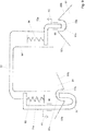
- the tarpaulin structure is characterized in that one of the spars has a one-sided unlocking locking arrangement, which advantageously makes it possible to set the spar with the carriage connected thereto to the guide and / or the substructure and thus a reliable locking of the tarpaulin structure or displaceable To ensure parts of the tarpaulin construction.
- the locking arrangement here comprises a first locking member and a second locking member, which are arranged on different longitudinal sides of the tarpaulin structure, so that the first locking member on the one longitudinal side for locking with the guide and / or the substructure care, while the second locking member on the another longitudinal side of the tarpaulin structure causes a lock with the substructure and / or the guide.
- first locking member for unlocking in a first unlocking direction and the second locking member for unlocking at the same time with the unlocking movement of the first locking member in a second unlocking direction is displaceable, wherein the first locking member and the second locking member together by pulling on the first locking member can be unlocked from outside the roof frame or the tarpaulin structure. It is thus not necessary to unlock the two latch members separately, but the appropriately hollow bar is used to connect the two latch members together such that the movement of the one latch member is transmitted to a movement of the other latch member, the connection protected is so loaded goods can not bother her.
- the first unlocking direction is expediently directed in the opposite direction to the second unlocking direction, so that when the first unlocking direction
- the first locking member is connected via an at least zugsteifes power transmission member such as a rope, a chain, a wire, a Bautenzug or the like with the second locking member, wherein expediently the tension-resistant power transmission member is guided in the connected to the frontmost pair of carriages spar.
- This makes it possible to arrange the power transmission member between the two longitudinal sides of the tarpaulin structure, without it being hampered by the loading of the substructure or the charge contained in the substructure. This ensures further advantageous that a pulling movement is reliably transmitted to the first locking member on the second locking member.
- the spar is in this case preferably designed as a U-shaped spar with two vertical legs and a horizontal base connecting the legs, so that the opposite unlocking directions can be easily achieved by the latch members arranged on the spar or in the extension of the spar.
- the spar can also be designed as braces connecting the two carriages in a common plane, or have any other configuration.
- the locking arrangement is not limited to upper openings of the substructure, but that also a lateral opening of a substructure, for example, a lateral loading opening of a so-called curtainsider is locked by the locking arrangement.
- the spar or its base or the bow then does not run in a horizontal plane, but in a vertical plane.
- the first unlocking direction and the second unlocking direction are the same unlocking directions.
- the first latch member is associated with a spring arrangement which loads the first latch member against the first unlocking direction
- the second latch member is associated with a second spring arrangement, which is the second Bar member loaded against the second unlocking direction.
- the first unlocking direction is directed vertically downwards and the second unlocking direction is directed vertically upwards, so that when the first locking member is pulled down, the second locking member is pulled upwards.
- the spring arrangement loads the latch members in each case counter to the respective unlocking direction, so that the spring arrangement must each be tensioned when unlocking.
- a longitudinal guide for each one locking member is provided on each of the foremost carriages or alternatively on the legs of the spar, which ensures that the locking member can be displaced only in the direction of the longitudinal guide.
- the longitudinal guide is expediently oriented in the respective unlocking direction and thereby also ensures that, in the event of a tensile force acting on the locking member with a component in the unlocking direction, the locking member is first unlocked and then the slide is first displaced along the guide.
- the first spring arrangement or the second spring arrangement is in each case arranged in the region of the longitudinal guide for the first locking member or the second locking member, so that the spring arrangement can be supported on the longitudinal guide or on the part, slide or spar which has the longitudinal guide.
- the other end of the spring assembly then supports e.g. against the respective spring member.
- the spring arrangement as a compression spring or as a tension spring formed, which loads the locking member against the respective unlocking.
- the design as a compression spring which can be easily attached to the latch member. If you do not want to let the variety of parts too large, can also be provided that the one locking member is loaded by a compression spring, while the other locking member is loaded by a tension spring, whereby the same installation space can be used.
- the locking member each having a guide portion which is lockable in a latch level in a first height level and can be released by vertical displacement of the latch bolt.
- the guide portion of the locking member is intended to come into contact with a locking member displacing the locking portion, which adjusts the locking member and the guide portion in the manner of a ramp or a wedge in its height.
- the locking member can be displaced in other ways than by external actuation in the unlocking.
- the latch traps has a preferably central locking position, wherein on the one hand or on both sides of the locking position is provided in each case an inlet slope, wherein the inlet slope cooperates with the guide portion to displace the locking member when closing the tarpaulin structure in the locking position.
- the guide member is moved with its guide portion along the inlet slope, wherein the inlet slope leads to an axial displacement of the locking member in the unlocking direction. If the run-in slope is exceeded, the spring arrangement causes the penetration into the central locking position, in which the movable parts of the tarpaulin structure are locked to the substructure and / or on the guide.
- the latch latch grips the latch member so as to prevent the movable parts of the top frame from displacing along the guide and / or substructure so that the latch member is caught in the latch latch.
- the inlet slope of the first latch bolt expediently drops toward the locking position of the first latch member, while the inlet bevel of the second latch latch rises toward the latching position of the second latch member.
- the inlet slopes are arranged or inclined so that they load the respective spring arrangement, which is relieved again upon penetration of the locking member in the locking position.
- At least one of the two locking members has a bent portion, wherein the guide portion is arranged at the end of the bent portion.
- the first latch member acts on the first latch member to a pull tab which protrudes between the tarpaulin and top frame over an outer region of the tarpaulin structure, wherein the pull tab for unlocking the locking assembly and for displacing the movable parts of the top frame along the guide is tangible. If the pull tab is pulled by an operator, in particular pulled down, the first latch member is displaced against the Verrieglungsraum until it is moved out of the locking position and allows a displacement of the associated carriage and / or spar along the guide.
- the pull tab for unlocking the locking assembly and for moving the movable parts of the top frame along the guide is tangible, so that not only the dragging or towing the carriage in the direction of the guide is caused by the pull tab, but also unlocking the carriage of the guide ,
- a latch bolt not only in the closed position of the tarpaulin structure is provided in each case a latch bolt, but also in the open position of the tarpaulin structure. This ensures that due to the mass and the bias due to the properties of the Plan the moving parts of the tarpaulin structure not be relocated towards the closed position and thus reduces access to the substructure.
- the spring arrangement here ensures that the locking members engage in the locking position.
- a tarpaulin structure for a substructure such as a truck, trailer, semi-trailer, railroad car, dump truck or container, comprising a top frame and a tarpaulin of weather-resistant material, the top frame having a plurality of spars, one inside each Have carriage which is displaceable along a guide. It is provided that one of the spars has an unlockable by a one-sided operation locking arrangement, wherein the locking arrangement comprises a first locking member and a second locking member, which are arranged on different longitudinal sides of the tarpaulin structure.
- the first locking member is in this case for unlocking in a first unlocking direction
- the second locking member for unlocking also displaceable in the first unlocking direction, so that the unlocking direction for the first and the second locking member is the same.
- the first latch member is associated with a first spring arrangement, which loads the first locking member against the first unlocking direction, so that without applying force from the outside, the first locking member is engaged against the unlocking direction.
- the first spring arrangement can also load the second latch member at the same time, but it is preferably provided that the second latch member is assigned a second spring arrangement which loads the second latch member counter to the first unlocking direction.
- a total of two namely a first and a second spring arrangement are provided which the first locking member and the second latch member respectively and / or collectively load. Due to the redundancy of the spring arrangements, safe operation is ensured even if one of the two spring arrangements fails due to a defect.
- the locking member each having a guide portion, which is preferably a distal end of the locking member formed as a bolt, wherein the guide portion is lockable in a first, lower height level in a latch latch and the latch bolt by vertical displacement to above is releasable.
- the latch bolt preferably blocks the latch member such that it prevents the movable parts of the top frame from displacement at least in one direction along the guide and / or the substructure. The locking member and the latch bolt are thus determined together for the locking of the moving parts of the top frame including the attached thereto tarpaulin.
- the latch bolt on a locking position in which the respective locking member is blocked or fixed by positive locking in at least one direction. Further, on the one hand or on both sides of the locking position an inlet slope of the latch bolt is provided, wherein the inlet bevel cooperates with the guide portion of the latch member to lift the latch member when moving the tarpaulin structure, for example, when opening or closing, and relocate to the locking position.
- This is expediently achieved in that the locking member is displaced by the inlet slope in the unlocking, usually under tensioning of the latch member associated spring arrangement, wherein the locking member after overcoming the inlet slope reaches the locking position, in which the associated spring arrangement, the locking member so before the latch bolt shifts that it comes to a form-locking blocking.
- the inlet slope of the latch bolt to the locking position of the locking member increases, so that the unlocking of the locking member in this case also points vertically upwards.
- the provision of the inlet slope acts as a ramp, that is, the force that initiates a user to move the moving parts of the top frame in the top frame is deflected by the ramp of the inlet slope in the unlocking.
- first locking member and the second locking member are each guided vertically on the two foremost carriage of the foremost spar.
- the vertical guide allows movement of the locking member only in unlocking or against unlocking, and at the same time ensures a minimum clearance between the frontmost slide to be locked and the guide to which the latch bolt is conveniently connected.
- a rocker arm is connected to the spar, which is at one end in operative connection with the first latch member and the other end is coupled to a vertically displaceable first pull lever which is vertically actuated for lifting the first latch member.
- the rocker arm is advantageously used primarily to the usual unlocking, which is given by an vertical pulling on a pull tab down for an operator, in a pulling movement in the unlocking, ie up, the first latch member is implemented.
- the pull tab is connected to the pull lever, so that the two parts perform the same vertical movement by their coupling. It is possible to provide the rocker arm and the pull lever also in the region of the second latch member, if an unlocking is to be provided on this side. But then the first latch member and the second latch member or connected thereto parts are to be coupled in such a way that both are raised or lowered at the same time.
- the unlocking takes place on the longitudinal side of the first locking member, so that the locking arrangement appropriately couples the second locking member with the first locking member and / or the first pulling lever, so that it is about a lifting of the second locking member comes synchronously and / or simultaneously with the first latch member.
- the first pull lever is expediently connected at the end to a first wishbone designed in the manner of a rocker, while the second latch member is connected at the end to a second wishbone designed in the manner of a rocker, with the first and second wishbones being respectively fastened to the foremost spar.
- the first wishbone and the second wishbone are then connected to each other via an at least tensile force transmitting member such as a rope or preferably a rod, wherein the at least zugsteife power transmission member is guided on the connected to the frontmost pair of carriages by the two wishbones.
- the power transmission member performs on actuation of the first pull lever down due to the first wishbone from a displacement in the direction of the longitudinal side of the first latch member, which is converted by the second wishbone in a vertical pulling movement of the second latch member. It is understood that to achieve this kinematic coupling, other parts may be used or provided, in particular further intermediate parts that may be connected between said parts.
- the at least zugsteife transmission member for avoiding buckling or hooking with charge in a seam or a sheath or eyelet, which is respectively secured to the spar, as long as the axial movement of the at least zugsteifen transmission member is not hindered thereby.
- the first spring arrangement is connected at one end to the spar, and the other end is connected to the rocker arm, so that the first locking member is not acted upon directly by the first spring arrangement, but indirectly by a tensile force on the first locking member facing away Lever arm of the rocker arm.
- a voltage of the first locking member is achieved in the locking direction in a favorable manner.
- the second spring arrangement is connected at one end to the carriage and the other end is connected to the second locking member, so that the second locking member is tensioned in the locking direction.
- the first spring arrangement can also be designed as described for the second spring arrangement. It is also possible for two springs to act on the first locking member, namely a first spring arrangement as explained above and a second spring arrangement as explained above.
- the first spring arrangement and the second spring arrangement are each designed as inexpensively available and easily checked for function tension springs, designed in the manner of a coil spring, running, which can be easily hooked into the available installation space.
- a pull loop for displacing the moving parts of the top frame along the guide is connected to a bracket connected to the foremost pair of carriages, which faces an adjacent pair of carriages, so that this pair of brackets coupled to each other when operating the pull loop not only in Shifting direction, but also burdened down.
- This is achieved in a favorable manner that the pair of interconnected, mutually facing bracket erects only at a very late time, and thus the foremost pair of carriages and the adjacent pair of carriages have a great distance during a large part of the displacement movement, which counteracts a tilting of the stiles by the unilaterally introduced pulling force.
- a tarpaulin structure for a substructure, such as a truck, trailer, semi-trailer, railroad car, dump truck or container, comprising a top frame and a tarpaulin made of weather-resistant material, the top frame having a plurality of spars, the one end Have carriage which is displaceable along a guide.
- at least one bracket is pivotally connected optionally to a pair of opposing carriages of the spar or to the spar, wherein the bracket with a bracket of a neighboring Holmes or pair of opposing carriages or a fixed part of the top frame forms a tarpaulin.
- the tarpaulin structure is characterized in that an endless drive device is provided, which is coupled to one of the two carriages of a frontmost pair of carriages, and in that the drive device comprises a toothed belt which is laid around two toothed rollers.
- the drive device is formed by a closed circulating toothed belt, which is driven by one of the two toothed rollers.
- the driven toothed roller can either sit on a driven shaft, or be in gear engagement with the driven shaft.
- the provision of a toothed belt is very advantageous due to the low slip and the precise controllability.
- the provision of a toothed belt allows the transmission of quite high forces on the carriage, which are required not only to relocate the foremost carriage, but also to pivot the kinematically coupled thereto parts such as cover bracket or strap or auxiliary bracket.
- the timing belt is disposed completely below the guide, so that it is not necessary, the timing belt to other carriages of the top frame or on pivoting parts of the Roof frame as an operating handle for a Abdeckbügel or the like to connect.
- an endless toothed belt is provided on both longitudinal sides, ie on both sides of the substructure, which is respectively coupled to one of the two carriages of a frontmost pair of carriages, so that the two opposing carriages of the foremost pair of carriages are synchronously opened. or closing direction can be moved.
- tilting is advantageously avoided, and also prevents damage to the top frame when blocking one of the two foremost carriages.
- the two toothed belts can be driven by a common drive shaft, which ensures the synchronicity of the drive movement.
- the drive shaft can be driven by an electric motor which can be actuated by actuating a pushbutton in the cab of a commercial vehicle, for example.
- the drive shaft can also be driven by a hand crank, or other suitable drive options are provided for this purpose.
- a preferred development is characterized in that at least one toothed roller, preferably the non-driven toothed roller, is coupled via a connecting plate with the guide, and that the at least one toothed roller is adjustable by a slot provided in the connecting plate or in the guide slot , In this way, the tension of the endless toothed belt can be adjusted, and weather or wear-related elongations are compensated.
- the timing belt can be aligned in this way also on the position of the carriage of the frontmost pair of carriages.
- a toothed roller in the case of a driven toothed roller, the driven toothed roller, on a substructure in Opening direction subsequent plate connected.
- the drive shaft can be arranged outside the actual receiving opening of the substructure, so that it does not come into contact with the transported goods.
- the toothed belt locks the frontmost slide in a closed position without slip, without the need for an additional locking.
- a manually operable locking can be saved.
- the locking of the foremost carriage also causes the positioning of the parts connected thereto, such as cover brackets and the like.
- the spars are designed U-shaped, and that a base of the U-shaped spar is arranged in the closed state of the tarpaulin structure at the same height as the carriage tolipte areas of the bracket.
- a tarpaulin structure which is in the closed state substantially at a height when the tarpaulin is connected to the spars and the bases of the bracket.
- the spar is arranged at a lower height than the minimum height of the bracket.
- the tarpaulin is also suitably connected to the legs of the U-shaped spars, possibly also in addition to the carriage. It is possible to connect the tarpaulin also to the legs of the U-shaped bracket. Due to the overall low height of the tarpaulin construction this can be particularly favorable for covering containers to be transported by road or rail be used. Due to the achievable distances between adjacent carriages, the tarpaulin structure also has a low weight.
- the carriage has at least one upper support roller and at least one lower counter-roller, wherein the at least one upper support roller and the at least one lower counter-roller with a peripheral surface abut the narrow sides of a rectangular cross-section guide rail of the guide, wherein at least one of the at least one upper support roller and the at least one lower counter-roller on either side of the peripheral surface each having an annular flange, and wherein the over the diameter of the peripheral surface projecting, facing each other end faces of the two annular flanges partially surround the broad side of the guide rail.
- the design of the support roller or the counter-roller which ensures the connection of the carriage to the rectangular guide rail, not only allows a displacement of the carriage in the direction of the guide rail, but also prevents slipping out of the support roller or the counter-roller of the guide rail by the Ring flanges enclose the broad side of the guide rail, wherein the radial projection of the annular flanges with respect to the peripheral surface is quite small.
- the carriage on two support rollers which rest vertically from above on the narrow side of the guide rail.
- this is arranged so that it spans an isosceles triangle with the two support rollers, and thus rests approximately in the middle between the two support rollers on the lower narrow side.
- the guide rail as an elongate rectangular profile part, preferably made of steel or anodized aluminum, can be easily procured and / or replaced, since such parts are well available as standard tape dimensions in the market.
- the guide rail is suitably connected to a lateral outer wall of the substructure via connecting means, wherein the connecting means pass through the broad side of the guide rail.
- connecting means for example, screws or rivets into consideration, which are suitably guided by a spacer sleeve to connect the guide rail as possible at a constant distance from the outer wall of the substructure. It is understood that the outer wall of the substructure should be as close as possible in one plane. If the substructure has indentations or projections or recesses, the spacer sleeves are to be dimensioned accordingly so that the guide rails connected on both sides of the substructure lie in parallel planes. Since manufacturers know about bulging containers when they are heavy or hot, the side walls may have a concave initial contour, which then has to follow the guide rail.
- the guide rail can be moved close to the outside of the substructure, wherein the guide rail outside the spacer sleeves and connecting means maintains a distance from the substructure, which allows that arranged on the carriage support rollers and counter-rollers embrace the broad sides of the guide rail.
- the connecting means enforce the broad side of the guide rail in the middle, so as not to stand in the way of an obstacle to the carrying rollers and counter rollers.
- a gap is provided between the guide rail and the outer wall of the substructure so that impurities falling between the guide rail and the outer wall of the substructure can fall, for example between two connecting means for connecting the guide rail.
- the distance of the guide rail from the outer wall of the substructure is not smaller than the extension of the narrow side of the guide rail.
- the distance between the guide rail of the outer wall of the substructure is equal to the extension of the narrow side of the guide rail, for example, each 8 mm.
- the thickness of the support roller or the thickness of the counter roller is narrower than twice the extent of the narrow side of the guide rail. This ensures that the idlers and counter-rollers can roll past the outer wall of the substructure without getting caught on the outer wall of the substructure. Since in fact only one annular flange of the support roller or the counter-roller projecting in the direction of the outer wall of the substructure on the guide rail, the thickness of the corresponding role is usually much smaller than the distance of the opposite broad sides of the guide rail, with a guide rail of 8 mm width and 40 mm height not greater than 2 - 3 mm thickness of the annular flange.
- the height of the guide rail is greater than the height of the support roller and / or the counter-roller.
- the support roller and / or the counter-roller are each formed slightly smaller than the height of the guide rail.
- the guide rail is formed from a plurality of successively arranged rail sections which are each connected to the outer wall of the substructure. This has the advantage that in the event of damage not the entire rail must be detached from the substructure, repaired or replaced and re-attached, but only the damaged area must be repaired. Furthermore, a guide rail formed in sections also adapts better to deformations of the substructure, for example of a container whose dimensions may change with filling or temperature of the filling. Finally, the design of the guide rail in individual allows Partial segments also the replacement of a carriage by a segment on which the carriage is arranged, is detached and then removed from the carriage, which can then be repaired or replaced. It is no longer necessary to dismantle the entire tarpaulin structure, to remove the tarpaulin from the top frame or to dismantle several parts of the top frame.
- the material from which the guide rail is made is suitably selected from the group comprising steel and anodized aluminum.
- Numerous containers are made of aluminum, so that an aluminum guide rail adapts well to the properties of the container. Steel is inexpensive and can be easily processed. When the anodized aluminum is the same surface hardness as steel, the steel rollers will not damage the guide rail.
- a particularly important requirement in a tarpaulin construction is that the tarpaulin structure must not laterally project significantly beyond the width of the substructure. Therefore, it is expediently provided that the outside of the guide rail is spaced less than 25 mm, preferably less than 20 mm, and if possible approximately 15 mm from the outside of the substructure.
- the distance of an outer side of the carriage to the outer side of the guide rail is less than the distance of the outer side of the guide rail from an outer side of the substructure.
- the connected to the pair of foremost carriages, facing away from the cover strap on the directly or via a linkage kinematics or by the tarpaulin connected bracket of the adjacent pair of carriages loaded in a direction opposite to the raising of the tarp is to ensure the longest possible force transfer in the direction of leadership.
- this load can be effected in that the angle of attack of the bracket is lower than in the other pairs of brackets, for example by a longer bracket is used, but above the mass of the bracket is increased, for example by a heavier material is used.
- the bias of the legs of the bracket to each other in the pairs of brackets may be formed differently, so that the load against the erection direction of the tarp is different by the different tension of the pairs of brackets.
- an expander or a spring can also provide such a force acting counter to the direction of erection.
- the carriages are connected to the guide only via at least one upper carrying roller and at least one lower counter roller, so that both the absorption of forces in the direction of the guide and in the horizontal direction perpendicular thereto, ie transversely to the substructure, by the carrying rollers.
- the U-shaped bars and stirrups can spread apart, thereby advantageously avoiding tilting.
- the movable parts of the top frame fold up from back to front. According to another preferred embodiment, it is provided that the movable parts of the top frame fold from front to back.
- the moving parts of the top frame are essentially the tarpaulin-folding aids, while the spars move together with the carriages connected thereto.
- the connected bracket between the Foremost pair of carriages and the immediately adjacent pair of carriages lift in the direction of opening as the last tarpaulin help.
- the tarpaulin is preferably connected to at least one of carriages and spars, conveniently on both the carriage and the spars, at the base of their resilient U-shape. Since the tarpaulin not only covers the substructure, but also limits the top frame laterally, a connection in the region of the legs of the U-shaped spars is expediently provided, wherein the connection can also be made in the region of the slide.
- the slides are suitably designed so that the carriage comprises a flat plate, and that the support rollers protrude on the same side of the plate on which the brackets are pivotally connected. This advantageously prevents moving parts, with the exception of the tarpaulin projecting laterally beyond the plane of the flat plate of the carriage and correspondingly achieves a very compact design.
- the spars are U-shaped, wherein a base of the U-shaped spar is arranged in the closed state of the tarpaulin structure at the same height as the carriage remote areas of the bracket. But it is also possible that the spars connect the carriage, without assuming a U-shape, when the spars are realized, for example, as Spriegelschaft or the like.
- the guide is expediently arranged at a distance from the substructure, which is greater than an upwardly directed narrow side of the Guide, so that impurities that should be stored on the narrow side, can fall down on both sides, without forming bridges and thus limit the functionality of the tarpaulin structure.
- the top frame is resilient in a horizontal transverse direction to the displacement direction to compensate for tolerances or deformations of the base.
- This is already achieved by the U-shaped configuration of the bracket, but also the Abdeckbügels, and the spars must be correspondingly compliant, so that in particular areas in which the distance of the mutual guide rails of the guide is not constant, can be traversed.
- This is based on the idea that, unlike other tarpaulin structures, in which a longitudinal beam of aluminum follows the top frame, that is, by deformation adapts to its dimensions, in the present case, the top frame should adapt to the deformations of the substructure.
- the overall structure of the tarpaulin is characterized in that the force for opening or closing can be introduced on one side, wherein the force for opening or closing is expediently introduced at only one of the two foremost carriages.
- a belt loop is connected to the frontmost slide, which can be gripped by a tool or by a motor-driven part. Since the top frame overbuilds a substructure, which also has a certain height, for example in a mounted on a vehicle dump truck, the resistance of the top frame against the opening force must be small.
- the roof frame is expediently wider than the substructure, so that it can be connected to an outer wall of the substructure.
- the parts of the top frame are expediently designed as steel parts, wherein the guide rail can be designed as an alternative to a design as a steel part as an anodized aluminum part, which interacts well with moving steel parts.
- An advantageous use of the tarpaulin structure arises as a cover in a container, in a truck, in a railroad car, in a swimming pool, in a carport, in a building as a roof replacement, or in a dump truck.
- Fig. 1 and 2 is a perspective view of the side or a side view of a tarpaulin structure 10 is shown, in which a plane-dotted plane 12 is indicated, which is not shown for better illustration in the other figures. Furthermore, the part of a silhouette of a container 14 is indicated by dashed lines, which is overbuilt by the top frame 16.
- the container 14 is formed, for example, as a dump, in the scree, but also dusting materials can be included, so the cover by the tarpaulin structure 10 is appropriate, may even be prescribed during transport on a truck.
- a front end wall 14a of the container 14 is formed as a dump flap, which is connected via a pivot joint 14b to the container 14 and which allows emptying of the container by dumping.
- the tarpaulin assembly 10 has on both sides of the container 14 at its lateral outer wall in each case a connected guide rail 20, which consists of a plurality of guide rail sections which are fixed at a distance from the container outer wall thereto, for example by rivets, screws or other suitable fastening means, the allow a defined distance to the outer wall of the container 14.
- the guide rail 20 is formed as a continuous part, composed of several sections, with a rectangular profile, which has in the installed state top and bottom as narrow sides and the broad sides parallel to the container wall.
- the top frame 16 projects beyond the end of the container 14, wherein in extension of the outer wall of the container 14, a substantially triangular console or plate 22 is connected to the back of the container 14, on which also the guide rail 20 continues.
- the purpose of the overhanging region is to be able to completely release the entire filling opening of the container 14 in the opened state, in that the movable parts of the convertible top frame 16 to be described can be moved there. In particular, no parts of the Tarpaulin 16 hinder the filling of the container 14.
- the triangular plate 22 extends higher than the plane of the guide rail 20 and extends the lateral outer wall of the container 14 at this height to the rear.
- the sides of a container will often be designated according to the direction in which it is moved, with the indicated flap 14a mostly being located on the rear of the vehicle; but in the present case, the area in which the moving parts of the top frame 16 collect when the tarpaulin structure 10 is open is referred to as the rear end, and the front end is the one which is released first from a closed tarpaulin structure 10.
- a container width spanning end stop 24 is provided which is substantially in a plane perpendicular to the guide rails 20 and has an inverted U-shape, and is connected to the ends of the U at the triangular plates 22 at the end thereof.
- the top frame 16 further includes a sliding roof assembly 30 movable along the guide rails 20, which can be opened to release the loading opening of the container 14 and also closed again for covering.
- the sliding roof assembly 30 includes a plurality of carriages 32 that can be slid along the guide rail 20.
- a longitudinal bisector which is the plane which is arranged centrally between the side walls of the container 14 or the plane which runs centrally and parallel to the guide rails 20, opposite slide 32 is connected to each other via a U-shaped rail 34, wherein Holm 34 has two curved corner pieces 34a and optionally an elongated connector 34b made of a round tube, which are plugged together, whereby a favorable standardization of the parts is achieved.
- All provided on the carriage 32 spars 34 are at the same height, which corresponds approximately to the height of the tarpaulin 12 when the tarpaulin structure 10 is closed.
- the tarpaulin 12 via suitable connection means with the bars 34th connected, for example via buckles or straps or trained in the tarpaulin 12 shots.
- the number of carriages 32 and thus the spars 34 may vary depending on the length of the tarpaulin structure 10.
- each pivot bracket 36 On each carriage 32 is further hinged on both sides of the beam 34 each pivot bracket 36 via a hinge 37, which is also fitted together via an elbow 36a and an elongated connector 36b each of a cylindrical tube. Also at the end stop 24, a swivel bracket 26 is articulated in height of the carriage 32, but not along the guide rails 20 is displaced. Overall, it is possible, the swivel bracket 26, 36 also opposite the carriage further up, so to the legs 34a formed by the corner pieces of the spars 34 to arrange. In tarpaulin superstructures, which, for example, only cover one loading platform, it is sufficient to use stirrups which are connected at a medium height of the stirrups.
- the swivel bracket 26, 36 are at a shallow angle of about 30 ° to the horizontal and close an angle of about 60 ° with the associated spar 34 and the end stop 24 a.
- the swivel bars 26, 36 can each be pivoted up into an angular position of approximately 90 ° to the horizontal, in which they run virtually parallel to the respective bars 34 or end stop 24.
- a covering yoke 46 is connected in a joint 47 on the side facing away from the remaining top frame 16 Fig. 5 shown downwardly pivoted, substantially horizontal position, that is about 0 ° inclination to the horizontal, and one in Fig. 6 shown vertical position, ie about 135 ° inclination to the horizontal, is pivotable.
- the cover bracket 46 in turn comprises two (repeatedly) bent bracket sections 46a and an elongate connector 46b, the distance from the spar 34 'connected to a frame portion 320 of the foremost carriage 32' are.
- Between the linkage 47 of Abdeckbügels 46 and the spar 34 ' is an auxiliary bracket 36' hinged in a joint 37 ', which projects at an angle of approximately 45 ° to the horizontal.
- a particularity of a tarpaulin structure 10 for a container 14 is that the container 14 has a high rigidity, so that the top frame 16 must follow the changes in shape of the container. These can be caused by thermal expansion, for example when hot filling, or deformation of the container, for example by the mass of the filling or by mechanical damage. Therefore, a feature of the top frame is that the U-shaped spars 34, pivot bracket 36 and cover bracket 46 allow some Y-direction resilient deformation, that is, the horizontal axis transverse to the displacement direction (X-axis). Thus, the top frame 16 can compensate for tolerances of up to 50 mm, without causing a lasting hindrance to the movement of the carriage.
- the above-mentioned angle also designate the angle of the plane in which the bracket is located to the horizontal - the pivot axis of the joints 37 is in each case in the Y direction.
- Brackets 36 of adjacent carriages 32 are connected to one another in the region of the angle pieces 36a via two linkage kinematics 38, of which one 38 is connected in particular in FIG Fig. 4 is shown enlarged.
- the linkage kinematics is presently designed as a knee joint, with a first link 38 a and a second link 38 b, which are pivotally connected to each other in a common joint 39.
- the first link 38a is connected to a rearwardly directed, hinged to the respective slide 32 leg of the elbow 36a of the bracket 36 via a hinge 39a, while the second link 38b at a forward facing, hinged to the respective slide 32 leg of the elbow 36a of the bracket 36 is connected via a hinge 39b.
- handlebars 38a, 38b are formed or arranged so that the knee is largely displaceable vertically downwards, but at the same time also a little outward to the tarpaulin 12 when moving the carriage 32 a bit outward to press.
- the links 38a, 38b are arranged quite stretched and each enclose an angle of about 20 ° to the horizontal, whereby the opening angle is about 40 °.
- the links 38a, 38b make an angle of nearly 86 ° with respect to the horizontal, whereby the opening angle of the links 38a, 38b is less than 10 °.
- Two linkage kinematics 38 are also provided between the bracket 26 hinged to the end stop 24 and the rearmost one of the stirrups 36 so that the movable part of the top frame 18 carried by the carriages 32, 32 'is associated with the non-moving part to which the end stop 24 belongs , is coupled.
- the tarpaulin assembly 10 is stiffened low in this area. It is possible to provide a handlebar kinematics 38 only in this area and otherwise to couple the brackets 36 together in a different way.
- bracket 36 is particularly preferably connected to the bracket 36 facing it via a linkage kinematics 38, which for the first time allows a flexible connection of the moving parts of the convertible top frame 16, ie the sliding roof arrangement 30, and of a fixed part, ie the end stop 24.
- the carriage 32 includes a carriage plate 32a to which two upper support rollers 33a and one lower counter roller 33b are pivotally connected, which rotate about an axis in the Y direction, and which, being connected on the inside of the carriage plate 32a, are shown in dashed lines ,
- the bent end piece 34a of the bracket 34 is disposed as a 90 ° bent pipe piece in a vertical plane in the Y direction and connected to an upper end of the slide plate 32a.
- the two angle pieces 36a of the two pivoting clamps 36 are pivotally connected via pivot pins 37a to joints 37 forming bores in the slide plate 32a.
- the ends of the angle pieces 36a have two projections 360, each with a hinge eye 361, are thus designed as a two-part spherical plain bearings, so that the slide plate 32a penetrates with their holes between the two projections 360. This makes it possible to achieve a particularly rigid guiding of the bracket 36 on the carriage 32. It can also be seen that no pivot limit is provided for the joints 37.
- Fig. 5 and 6 show in greater detail the foremost carriage 32 'with hinged thereto reinforced spar 34', from which in the opening direction hinged to the joints 37 bracket 36 goes off.
- bracket 36 On the articulation 37 with respect to the spar 34 'opposite side of an auxiliary bracket 36' is articulated in a joint 37 ', which turns out to be less high than the bracket 36 and also reversed U-shaped.
- the auxiliary bracket 36 ' forms, as in Fig.
- the carriage 32 ' has a fairly wide slide plate 32a', which is guided over two support rollers 33a 'and each support roller 33a' opposite. With respect to.
- the guide 20 arranged counter-roller 33b ' is guided.
- the carriage 32 further comprises two guide rollers 51 ( Fig. 6 ), which are rotatable about a vertical axis and which bear against the broad side of the guide rail 20, wherein it is possible that the guide rollers 51 also roll against the side wall of the substructure 14.
- the carriage 32 ' may also provide four guide rollers 51.
- the foremost carriage 32 'in each case has a frame section 320, which extends above the guide 20 in a horizontal plane which coincides approximately with the linkages 37, 37' and forward, ie in the closing direction of the tarpaulin structure 10, the foremost carrying roller 33a 'towers over.
- the frame portion 320 is in this case formed as a U-shaped bent sheet metal part, which is fixed to the base plate 32a 'of the foremost carriage 32' by means of rivets 321 or alternatively also screws.
- the frame portion 320 is formed open at the bottom and thus connects two plate halves 322a, 322b of the base plate 32a 'of the foremost carriage 32', which continues are connected to each other via other connecting means.
- the pivot bearing for the linkage 47 of the Abdeckbügels 46 is provided, also a further pivot bearing 61 for a further described below in more detail armature 60th provided for pivoting the Abdeckbügels 46.
- the upwardly facing surface of the portion 323 forms a support for the Abdeckbügel 46 in its lowered position, whereby the Abdeckbügel 46 is coupled to the carriage 32 'and rests on the frame portion 320 on this, so that an immediate resting on the base 14 avoided becomes.
- the frontmost slide 32 'after unlocking a locking assembly 70 which is explained in more detail below, can be displaced along the guide 20 with pivoted Abdeckbügel 46, so that the process of unlocking the locking assembly 70, the displacement of the Foremost spar 34 'and the pivoting of the Abdeckbügels 46 not simultaneously, but can be done in a short sequence.
- the frame portion 320 also forms a support portion 320a on its upwardly facing base for the leg 46a of the cover bracket 46 when in its raised position.
- the swivel bracket 46 is, as in Fig. 5 and 6 to recognize in greater detail, composed of a plurality of pipe sections, namely, two each of a lateral leg defining bent portions 46 a, which are each pivotable in the linkage 47, and a tubular connecting piece 46 b, which connects the two bent portions 46 a together.
- the bent portion 46a is bent several times, so that an angle-shaped leg is formed, which then has an angle which is extended by the tubular connecting piece 46b.
- the angular leg 46a has a short leg portion 460 and a long leg Leg portion 461 which are mutually bent by a leg angle of about 120 °, wherein the leg angle averted end of the short leg portion 460 is pivotally connected to the hinge 47 of the foremost carriage 32 ', and the leg angle facing away from the end of the long leg portion 461 end is bent in the direction of the tubular portion 46b.
- the short leg portion 460 and the long leg portion 461 are interconnected by a strut 463 which itself is angled and with the short leg perpendicular to the short leg portion 460 while its long leg converges at an acute angle with the long leg portion 461.
- the strut 463 stiffens the leg 46a in a vertical plane by constructing a kind of triangle.
- the side of the connecting strut 463 facing away from the long leg section 461 forms a support region 463a, which forms a support surface which, when the cover yoke 46 is pivoted down, comes to lie completely on the support 323.
- the cover bracket 46 rests on the support 363 in the pivoted-down state and can easily, in particular without noise, be displaced along the guide 20 with the carriage 32 ', without being guided on the guide rail 20 itself.
- a hook 80 is pivotally connected via a hinge 81 at its end, which is connected to the long leg portion 461 ( Fig. 5 ).
- the hook 80 has a latching recess 82, which can be coupled to a bolt 84 inserted in an eye 84 at the end remote from the spar 34 'end of the frame portion 320 by the force of the hook 80 so that the latching projection 82 slides behind the bolt 85 and thus prevents a swiveling up of the Abdeckbügels 46 at a horizontal arrangement of the tarpaulin structure 10.
- the hook 80 has a plurality of latching portions 82, which at swung down hook 80 are approximately arranged with each other and thus look like a sawtooth, so when not completely swung down Abdeckbügel 46, for example, due to deformation, contamination or protruding charge, however, a locking of the hook 80 is given to the bolt 85.
- a particular advantage of the hook 80 is that in the case where the substructure 14 is pivoted, for example, to cause a dumping of load from the substructure 14 by pivoting the flap 14a about the linkage 14b, the hook 80 is also disengaged with the bolt 85 passes.
- the pivoting movement of the flap 14a about the linkage 14b requires that a part of the flap 14a is pivoted into the area in which the closed Abdeckbügel 46 is with the plane 12 connected thereto.
- the pivotal movement of the base 14, however, causes the hook 80 is also pivoted due to gravity, so that the hook 80 is released from the anvil 85 and the Abdeckbügel 46 allows a pivoting movement. In this way, it is favorably prevented that the flap 14a of the substructure 14 deforms the cover bracket 46, despite its locking on the frame section 320 of the carriage 32 '.
- the hook 80 further includes a stop surface 80a which allows the hook 80a to be released from its locked position with the bolt 85.
- a stop member 89 is provided on the guide 20, the bolt-like projecting from the broad side of the guide rail 20 and against the opening surface of the tarpaulin structure 10, the stop surface 80a is spent.
- the hook 80 is pivoted about the link 81 and thus out of engagement with the bolt 85 on the frame portion 320. This advantageously makes it possible that the carriage 32 'can also be displaced along the guide 20 with the cover bracket 46 connected thereto and the locking of the cover bracket 46 on the foremost carriage 32' is released without the hook 80 having to be actuated separately for this purpose.
- the abutment surface 80a allows the hook 80 to be disengaged from the bolt 85 upon axial displacement of the carriage 32 ', thus decoupling the locked covers 46 and carriages 32'.
- the hook 80 thus has two unlocking options, namely on the one hand by pivoting of the base 14 and on the other by axial displacement of the moving parts of the top frame 16 along the guide 20th
- the hook 80 in particular when it is connected to the frame portion 320, have a guide surface which allows pivoting of the hook when it overruns the stop member 89 when moving the foremost carriage 32 'in the closing direction, so that the hook 80 is not blocked with the stop member 89.
- the stop surface 80a in which the hook 80 is connected to the cover bracket 46, the stop surface 80a also assumes the function of the guide surface.
- the linkage 60 comprises an actuating link 62 which is articulated in the bearing 61, and an intermediate link 63 articulated to one end in the bearing 465a and other ends via a hinge 64 spaced from the bearing 61 on the actuating link 62 is provided is stored.
- the pivot pins in the bearings 465a, 64 are each designed as sliding blocks, which are each displaceable in circular track link tracks 66, 67 about the hinge 47 and the articulation 61, wherein the slide tracks 66, 67 a lateral buckling of the links 62, 63 of the steering gear 60 should prevent. It is possible to omit the slide tracks 66, 67 formed in the carriage 32 ', without the basic function of the link mechanism 60 being impaired as a result. A lateral guidance of the parts of the steering gear 60 in the frame portion 320 is possible.
- the articulation 61 of the actuating arm 62 of the articulation 47 of the Abdeckbügels 46 is upstream, wherein the two linkages 47, 61 are arranged in the same horizontal plane.
- the distance of the articulation to the respective slide track 66, 67 is different, so that a transmission ratio between the two sliding blocks 465a, 64 is advantageously achieved.
- the actuation link 62 cooperates with a deflector 69 mounted on the guide rail 20, which may be a roller or a pin or the like. If the carriage 32 'is displaced, the actuating link 62 engages with its deflecting member 69 facing inside 62 a of the articulation 61 averted curved end portion with the deflecting member 69 into engagement, and the deflecting member 69 causes the actuating arm 62 to pivot about the linkage 61st As a result is forced over the intermediate link 63 of the extension 465 to a pivoting movement, whereby the Abdeckbügel 46 is swung up.
- the slotted guides 66, 67 are designed so that they can limit the pivot angle of the Abdeckbügels 46.
- the inside 62a of the actuating link 62 comes into contact with the deflecting member 69, so that upon further displacement of the carriage 32' along the guide 20 the covering clip 46 is swung upwards. Due to the curved or curved shape of the end portion of the actuating arm 62 of the actuating arm 62 is pivoted to a position in which the end 620 of the actuating arm 62 is in a plane above the deflector 69, so that the carriage 32 'with the link mechanism 60 and the then arranged in extension of the frame portion 320 arranged actuating lever 62 can slide over the deflecting member 69.
- the slide track 67 may have such a supernatant that the actuating link 62 is just lifted above the coupling member 69, but then falls back a bit, so that the outer side 62b of the actuating link 62 when returning the frontmost slide pair 32 'with its outer Page 62b passes against the deflecting member 69 and is displaced in the reverse direction, so that the Abdeckbügel 46 is pivoted back into its lowered position.
- the Abdeckbügel 46 each have on its two legs 46a each have an extension 465, and that on both sides in each case a link mechanism 60 for pivoting the Abdeckbügels 46 is provided on the extension 465, wherein on one side of the top frame 16, a deflecting member 69 is provided for controlling the Aufschwenk Gay the Abdeckbügels 46, when on the other side of the top frame 16, a deflecting member 69 is provided for controlling the swing down movement of the Abdeckbügels 46 ,
- the deflecting member 69 is provided at such a distance from the carriage 32 'or the link mechanism 60 hinged thereto, that when the carriage 32' is displaced axially in the X direction, first the hook 80 is released and then only the first Cover bracket 46 is swung open. It is possible to connect the link mechanism 60 to the hook 80, so that instead of striking the hook 80 it is displaced from the link mechanism 60, then under gravity, the link mechanism 60 must be pivotally carried out to disengage the hook 80 to bring the counter bearing 85, which is given here but without further notice.
- the link mechanism 60 allows a partial pivoting of the cover 46 when tilting the base 14th
- Figs. 8A and 8B is enlarged in each case a part of the foremost carriage 32 'one longitudinal side ( Fig. 8A ) and the other longitudinal side ( Fig. 8B ) of the tarpaulin assembly 10 to which the locking assembly 70 is connected.
- the locking arrangement 70 has a first locking member 71, which in Fig. 8A is shown, wherein the first locking member 71 is designed as flat material blank of a strip-shaped band.
- the locking member 71 has a first portion 71 a, which is arranged axially displaceable in a provided on the foremost slide 32 'longitudinal guide 90.
- the first locking member 71 has a the first portion 71 a facing away, a kind of U double bent end portion, which includes a directed towards the longitudinal bisecting fold and a perpendicular thereto further folding, the further unfolding having an upwardly directed end, a guide portion 71 b of the latch member 71 forms.
- a second locking member 72 is longitudinally guided in a corresponding longitudinal guide 90 with a first portion 72a, wherein the protruding from the longitudinal guide 90 second locking member 72 has a of the guide portion 72a in the longitudinal guide 90 facing away in the manner of a Z double bent portion member having a first folding portion lying in a horizontal plane in the direction of the longitudinal bisector and a further folding portion vertically projecting therefrom with one end forming a guide portion 72b of the second locking member 72.
- the first locking member 71 is in the region of the guide rail 20 on the base 14 associated with a first latch bolt 91, and on the opposite side of the second latch member 72 is associated with a second latch bolt 92 which is screwed to the inside of the longitudinal guide 20 such that the support rollers 33a 'and counter rollers 33b' can pass along the rail 20 on the latch bolt 92.
- the latch bolt 91 of the first latch member 71 and the latch bolt 92 of the second latch member 72 each have a central recess 91 a, 92 a, which is bounded on both sides by the latch latch such that when the latch member 71, 72, this not in the direction of Guide line 20 can be moved so that the carriage 32 'is locked in each case on the rail 20.
- the first latch member 71 is for unlocking in a first unlocking direction, Y1 (FIG. Fig. 9 ), which points vertically downward, displaceable, so that the guide portion 71 b passes below the latch bolt 91 and thus on the latch bolt 91 is displaced past.
- the second latch member 72 is for unlocking in a second locking direction Y2 (FIG. Fig. 9 ), which is opposite to the first locking direction Y1 and thus faces vertically upward, whereby the guide portion 72b of the second locking member 72 is released from the latch 92.
- the first locking member 71 by means of a in the front spar 34 ' guided from one longitudinal side to the other longitudinal side, designed as a cable 77 at least zugsteifes power transmission member connected to each other, wherein the cable 77 is connected to the two locking members 71, 72. If the first latch member 71 is pulled down via a pull tab 79, which is connected to the first latch member 71 via a hinge 79a, the cable 77 causes the second latch member 72 to pull upwards. It is also possible to use a puller instead of the cable 77 Linkage to provide a chain or other at least tensile force transmitting member.
- the latch bolt 91, 92 has a central recess 91a, 92a which forms a locking position which is sufficiently wide that the latch members 71, 72 can engage therein.
- an inlet bevel 91 b, 92 b is formed which protrudes from a base region connected to the guide rail 20 such that it engages with at least the downward-pointing end of the guide member 71, 72.
- the inlet slope is overrun in each case in the X direction and has a slope in the manner of a ramp in the Y direction.
- the first locking member 71 and the second locking member 72 are each biased by a coil spring designed as compression spring 93, 94 in the direction of the recess 91 a, 91 b of the latch 91, 92, so that the first latch member 71 is pushed upwards, and second latch member 72 is pressed down.
- the first spring arrangement containing the first compression spring 93 and the second spring arrangement containing the second compression spring 94 is arranged in each case in the region of the longitudinal guide 90, wherein a laterally projecting from the locking member 71, 72 region which forms an abutment for the compression spring 93, 94, and a shoulder provided on the longitudinal guide 90 forms the second abutment for the respective compression spring 93, 94, which is schematically illustrated in FIG Fig. 9 is shown.
- Fig. 8A One recognizes in Fig. 8A in that the inlet bevel 91b of the first latch 91 extends in the direction of the locking position 91a away from the longitudinal guide 90, ie is tapered down, while the inlet slope 92b of the second latch 92 ( Fig. 8B ) in the direction of the locking position 92a upwards, ie in the direction of the guide 90, is chamfered.
- the guide portion 71 b of the first latch member 71 is biased toward the lower surface of the inlet slope 91 b of the spring 93, while the guide portion 72 b of the second latch member 71 is biased towards the upper surface of the inlet slope 92 b of the spring 94.
- the spring 93, 94 displaces the latch members 71, 72 under relaxation against the unlocking Y1, Y2, so that the latch members 71, 72 and their guide portions 71 b, 72 b are held in the locking position 91 a, 92 a, thus locking the foremost Carriage 32 'on the guide 20th
- rollers 33a, 33b each have a grooved circumferential surface, wherein the groove width is equal to or slightly larger than the narrow side of the rectangular guide rail 20.
- the slide 32, 32 ' centered independently on the narrow side of the guide rail 20th , And it is advantageously avoided that the rollers can slip off the rail 20.
- Each additional carriage 32 has, as in Fig. 3 shown, two upper support rollers 33a and one or two counter-rollers 33b, the peripheral surface in grooved area with an upper narrow side and a lower narrow side of the guide rail 20 is in contact.
- the rollers 33a, 33b On both sides of the peripheral surface, the rollers 33a, 33b have a flange, also referred to as an annular flange, which encloses the broad side of the guide rail 20 lying in a vertical plane over a small height corresponding to the projection of the annular flanges over the peripheral surface , The supernatant is about a few millimeters, so that sufficient height of the guide rail 20 of about 40 mm remains to set screws for connection to the container 14 through the broad side approximately in the middle.
- the height of the rollers 33a, 33b is equally including annular flange 38 mm and is thus less than the height of the guide rail 20.
- the distance of the guide rail 20 from the outer wall is equal to its width, namely 8 mm (or 7.5 mm) ,
- the distance of the outside of the carriage 32, 32 'to the outside of the guide rail 20 is about 10 mm, so that the projection of the top frame 16 on the substructure 14 in the Y direction on each side less than 30 mm, preferably around 25 mm accounts.
- the top frame 16 of the tarpaulin structure can compensate for tolerance variations in the distance between the two guide rails 20 of up to +/- 50 mm by the brackets 26, 36, 36 ', 46 and spars 34 are spread apart with their legs from each other or compressed towards each other.
- the elasticity of the stirrups 26, 36, 36 ', 46 and spars 34 provides this clearance at the level of the carriages 32, 32'.
- a drawstring formed as a wire is connected on both longitudinal sides of the tarpaulin structure 10 to the carriages 20 and the end stop 24.
- the drawstring prevents the carriages 32, 32 'from taking a greater distance from each other than desired for the closed position, and because the drawstring is less extensible than the tarpaulin connected to the spars 34, 34' and stirrups 36, the drawstring relieves the tarpaulin 12 too.
- the drawstring is in this case firmly connected to the support plates of the carriage and guided in a hem of the tarpaulin 12, so that it can not hang down and at the same time biases the hem against the base 14.
- the tarpaulin 12 can, in order to better absorb the forces introduced by the carriages, have a reinforcement in the region of the carriages, such as a built-in belt.
- the cover bracket 46 or the front carriage 32 ' is unlocked, and the operation of the top frame 16 can be made from only one side.
- the pull loop 79 is pulled in a first step with a downward component.
- the latch assembly 70 then unlocks the latch members 71, 72 from the latch latches 91, 92, and as soon as the foremost carriage 32 'is displaced a little way in the X direction, the latch members 71, 72 can no longer from the springs 93, 94 in the Bar latch 91, 92 are pushed back.
- the hook 80 with its abutment surface 80a strikes against the stop member 89, so that the hook 80 pivots about its articulation 81 and thus releases the cover stirrup 46 from the foremost carriage 32 '.
- the actuation link 62 strikes the Umlemkglied 69 so that the movement for displacing the foremost carriage 32 'is converted into a Aufschwenkhik the Abdeckbügels 46 until this with its short leg portion 460 on the area 320 a the frame portion 320 is located.
- the latch assembly 70 locks the package to another latch latch 91, 92.
- the closing movement takes place in reverse order to the opening movement, whereby here too the introduction of force takes place unilaterally on the foremost carriage 32 ', for example via a loop connected thereto.
- a motor-driven traction means to one of the foremost carriages 32 'in order to automatically open and close the tarpaulin 12.
- the rear latch assembly is unlocked, then the tarpaulin folding aids 36, 38 unfolded and finally pivoted down over the link mechanism 60 of the cover 46, after which the hook 80 engages with the anvil 85 before the latch members 71, 72 back into the front latch traps 91, 92 are transferred over the inlet slopes 91 b, 92 b and spent there under relief of the springs 93, 94 in the locking position.
- FIG. 10 to 20 5 another embodiment of a roof frame 1010 for a tarpaulin structure is shown, wherein the same reference numerals as in the preceding embodiment denote the same or structurally comparable parts, and changed parts, which are substantially discussed in the following explanations, are incremented by 1000.
- a handlebar kinematics 38 only between the pivoted on the end stop 24 pivoting bracket 26 and the rearmost pivot bracket 36 of the Sliding hood assembly 30 is provided.
- the further bracket 36 of the sliding roof assembly 30, however, are coupled to each other at their connecting pieces 36b, wherein a Schwenkwinkelbeskyr 1038 prevents sliding over the bracket 36.
- stirrups 36 or their corner pieces 36a are connected on one side only to the base plate 32a of the carriage 32, which is connected displaceably along the guide 20 by the carrying rollers 33a and the counter-rollers 33b.
- the spar 34 is in this case firmly connected to the base plate 32 a of the carriage 32.
- a frame portion 1320 is connected to the foremost pair of carriages 32 'interconnected by the foremost stile 34' carrying both a carrying roller 33a and a counter-roller 33b disposed on either side of the guide 20, where further on the frame portion 1320 of the foremost carriage 32 'an auxiliary bracket 1036 is pivotally connected.
- the auxiliary bracket 1036 is in this case so far from the foremost spar 34 'spaced that he can skip so that he can lean against the bracket 34'.
- a Abdeckbügel 1046 is pivotally connected to the compassionabschnit 1320, which is pivotable about a hinge 1047. The cover bracket 1046 rests in the closed position (FIG. Fig.
- the cover bracket 1046 projects beyond the closed state ( Fig. 14 ) the frame portion 1320, wherein approximately at the center of the leg 1046 a, a hinge is provided which supports a hook, not shown, which connects to the frame portion 1320 connects.
- the cover bracket 1046 has an operating link 1062 which exits from the leg 1046a and can be rotated by a deflecting element attached to the guide rail 20 such that the cover bracket 1046 is displaced in its raised position.
- the deflecting member is in this case designed in the manner of a folding with a slope which forms a sufficient resistance for lifting the Abdeckbügel 1046, but can be run over in the event of the return of possibly lowered Abdeckbügels.
- a first biasing member 1901 connects the cover bracket 1046 to the auxiliary bracket 1036 in the region of their connecting pieces 1046b, 1036b.
- the biasing member 1901 is hereby designed as a belt, which in the lowered configuration of the Abdeckbügels 1046 as in Fig. 14 is stretched, but with raised cover as in Fig. 15 is shown largely relaxed. So far, the first biasing member 1901 substantially serves to lift the cover bracket 1046 when the lock between the cover bracket 1046 and the frame portion 1320 is released. As a result, the force to be introduced in the actuating link 1062 is less than predetermined by the mass and the dimensions of the cover bracket 1046.
- the connecting piece 1036b of the auxiliary bracket 1036 is coupled to the connecting portion of the foremost rail 34 'by a second biasing member 1902 configured as an elastic belt.
- the two ends of the second biasing member 1902 are in this case connected to the bracket 34 'in the region of the connecting piece, while a central region is placed twice around the connecting piece 1036b of the auxiliary bracket 1036. It is thereby advantageously achieved that the second biasing member 1902 is not fully relaxed even when the auxiliary bracket 1036 is abutted against the foremost rail 34 ', the tension acting on the auxiliary bracket 1036 also being over the first biasing member 1901 is transferred to the cover 1046.
- the length of the actuation link 1062 is approximately two-thirds of the distance of the connector 1046b from the pivot point 1047, thus providing a sufficiently favorable translation that allows an operator to swivel the cover 1046 by pulling on the puller 78. Regardless, the cover bracket 1046 pivots even when the base 14, such as a dump body, is tilted, as explained for the previous embodiment.
- a locking arrangement 1070 which allows unlocking of the sliding roof assembly 30 provided on the guide 20 locking positions by operating a pull tab 79.
- the sliding roof assembly 30 can be displaced by pulling on the pulling device 78 along the guide 20, the cover bracket 1046 is pivoted up and the locking member, which defines the covering bracket 1046 on the frame portion 1320, is released.
- the provision of the pulling device 78 on one of the brackets 36 ensures that the force required in particular for pivoting the covering bracket 1046 does not primarily lead to the erection of the bracket 36, since the pulling movement also pulls it downwards.
- the locking arrangement 1070 comprises a first locking member 1071 and a second locking member 1072 which are respectively arranged on different longitudinal sides of the tarpaulin structure 1010 and which in the region of the foremost carriage 32 'each displaced in an unlocking direction Y1, that is to be lifted to the sliding roof 30th to unlock.
- the first The latch member 1071 and the second latch member 1072 each comprise a long pin which is axially displaceable in a corresponding vertical guide 1070a of the carriage 32 ', wherein an area of the latch member 1071, 1072 projecting beyond the region of the base plate 32a of the foremost carriage 32' respectively projecting up and down over the base plate 32a.
- the first latch member 1071 includes an L-shaped shoulder 1071 b provided at the upper end of the latch member 1071, with which the depth of penetration of a distal shaft portion 71a of the latch member 1071, which is designed as its tip, relative to a first latch 1091 can be adjusted.
- the latch bolt 1091 is substantially formed by an L-shaped plate having an inlet slope 1091b, which increases in the closing direction, ie upon displacement of the sliding roof assembly 30 from the open to the closed position.
- the inlet bevel 1091 b thus raises the locking member 1071 until it is lowered under the load of a yet to be explained in more detail spring assembly 1093 in its locking position 1091 a.
- the second locking member 1072 is provided with a guide portion 1072a formed as a tip and an L-shaped shoulder 1072b and a locking catch 1092 with an inlet bevel 1092b and locking position 1092a.
- the guide portion 1072b of the second latch member has, at its end facing away from the guide portion 1072a, another fold 1072d parallel to the plane of the beam 34.
- the upper end of the L-shaped shoulder 1071 b of the locking member 1071 is connected end to end in a joint 1073 a hinged to a rocker arm 1073, which in turn hinged on a clamp 1073 b and a central hinge 1073c to the spar 34 'is connected.
- a pull lever 1075 is pivotally connected to a bolt 1073e, which runs substantially parallel to the leg 34a 'of the spar 34'.
- the pull lever 1075 is L-shaped folded from a sheet steel part, so that the two legs 1075a, 1075b include a right angle of about 90 degrees.
- a pin 1073 e is provided, which couples the pull lever 1075 with the slot 1073 d of the rocker arm 1073.
- a terminal 79a of the pull tab 79 is connected to the leg 1075a of the pull lever 1075, so that when pulling on the pull tab 79 connected to the latch member 1071 lever arm of the rocker arm 1073 is pulled down about its central axis of rotation 1073c and in this case the latch member 1071 after pulls up.
- first spring assembly 1093 On the side facing away from the locking member 1071 leg of the rocker arm 1073 also acts on a first spring assembly 1093, which is connected via clamp 1093a to the spar 34 '.
- the first spring assembly 1093 biases the rocker arm 1073 such that the latch member 1071 is biased to its lower position. The bias of the first spring assembly 1093 is therefore overcome when pulling on the pull tab 79 to bring the first latch member 1071 out of engagement with the latch 1091.
- the L-shape of the pull lever 1075 translates the vertical movement in the plane of the rocker arm 1073 into a substantially horizontal movement in the plane of the second leg 1075b of the pull lever 1075.
- a free end of the leg 1075b of the pulling lever 1075 is in this case coupled to a first wishbone 1074 designed in the manner of a rocker in a pivot point 1074a, which is articulated at an opposite end in a pivot point 1074b with a force transmission member 1077 designed as a pull rod.
- the wishbone 1074 is coupled to a base 34b of the U-shaped beam 34 ', so that upon a displacement of the pull lever 1075 down the Connecting rod 1077 by the pivoting of the wishbone 1074 to the longitudinal side at which the pull tab 79 is provided, is pulled.
- the tensile force on the pull loop 79 is also on the opposite side, in Fig. 17 is shown, as further explained below.
- a connecting rod 1077 instead of a connecting rod 1077, a rope or a chain could be provided, since it essentially depends on the transmission of tensile forces, and a tension-resistant power transmission member is sufficient for this purpose.
- a tension-resistant tie rod 1077 is also preferred. Furthermore, this ensures that in the event of failure of one of the two spring assemblies 1091, 1092, the bias of the remaining spring assembly is sufficient to lock both sides of the top frame 1010 reliably.
- the end of the connecting rod 1077 facing away from the pull-tab 79 is coupled via a bearing 1078a of a second wishbone 1078 designed in the manner of a rocker, which has a slot 1078b on the end opposite to a link 1078c for attachment to a lug of the spar 34 '.
- the wishbone 1078 is in this case positioned so that upon movement of the connecting rod 1077 in the direction of the pulling loop 79 of the elongated hole 1078b having leg of the wishbone is raised.
- a bolt 1072 e provided on the fold 1072 d is accommodated, which causes the connection of the second latch member 1072 with the second wishbone 1078.
- the connecting rod 1077 is pulled toward the longitudinal side of the first latch member, the second wishbone 1078 pulls the second latch member against the locking direction and the bias of the second spring assembly 1094 up.
- the second spring assembly 1094 also engages the shoulder 1072b in an eye 1094c formed therefor, with the other end of the second spring assembly 1094 received on the carriage 32 '.
- the second spring arrangement 1094 causes the second locking member 1072 to be tensioned in each case in the vertical direction downward, so that the second spring arrangement 1094 designed as a tension spring likewise has to be overcome when the tensioning loop 79 is actuated.
- a first spring arrangement 1093 which is associated with the first locking member 1071
- a second spring arrangement 1094 which is associated with the second locking member 1072, it is ensured that both spring members 1093, 1094 are each biased in the closing direction. Although this would be sufficient for a common spring arrangement for both latch members by the redundant training by providing two spring assemblies 1093, 1094, the security of the lock is additionally increased.
- the guide portion 1072a of the second latch member 1072 is made slightly shorter or set higher than the guide portion 1071a of the first latch member 1071. This ensures that when the first latch member 1071 disengages from the associated latch latch 1091 , In any case, the second latch member 1072 is released from the second latch bolt 1092, since it is released first. This prevents that the sliding roof assembly 30 is already pulled in the opening direction when the second latch member 1072 is still in engagement with the second latch bolt 1092.
- the locking members 1071, 1072 are each adjustable in their depth of engagement, so that occurring by play, tolerances and deformations of the convertible top frame synchronization errors when unlocking the locking members 1071, 1072 can be compensated.
- the adjustment is made by adjusting the bolts having the tips 1071a, 1072a on the associated L-shaped shoulder 1071 b, 1072 b, the bolt may be provided for this purpose with an external thread to be fixed by means of screws in its height to the respective paragraph 1071 b, 1072 b.
- the paragraph 1071 b, 1072 b and the bolt and the other connecting means then form the locking member 1071, 1072, wherein the paragraph may also be shaped differently than shown in the present example.
- a guide 1070a is provided in each case for one of the locking members 1071, 1072 in the carriage 32 ', which makes it possible for the locking members 1071, 1072 to be displaced vertically in each case, and also for the latch bolt 1091, 1092 can not escape ,
- Fig. 21 and 22 show a further embodiment of a hood frame 2010 for a tarpaulin structure, which is basically constructed as the previous embodiment, so that the differences from the previous embodiment of the top frame 1010 are incremented by another 1000.
- the top frame 2010 is characterized by an endless drive device 2950, which is provided on each of the two longitudinal sides below the guide 20 and which is coupled to one of the two carriages 32 'of a frontmost pair of carriages.
- the drive device is in this case designed as a toothed belt 2952, which is placed around two toothed rollers 2951.
- the drive device 2950 designed as a toothed belt 2952 is folded over two toothed rollers 2951 connected at opposite ends of the longitudinal side of the base 14, wherein the roller 2951 provided in the region of the foremost carriage 32 'with the tarpaulin assembly closed is provided on a fitting 2953 which has a Setting possible.
- the fitting 2953 is coupled via a connection with the guide 20, which allows a pivoting movement, wherein in the Fitting 2953 a slot 2954 is provided which allows a setting with respect to a pin 2955. Accordingly, the timing belt 2952 can be stretched or relaxed.
- the two toothed belts 2952 enable a precise displacement of the foremost carriage, so that a common drive shaft for both toothed belts 2952 is provided.
- the toothed belts have practically no slippage and do not slip, so that even with multiple opening and closing movements, no tilting of the towed foremost carriages 32 'of both longitudinal sides occurs.
- the tarpaulin structure 10 covers a container 14. It is understood that the tarpaulin assembly 10 can also be used to cover other mobile or transportable or stationary, substantially cuboid or at least a rectangular opening having substructures, for example, the roof of a truck, a truck trailer, a bus, a Tipping body or semi-trailer, for the roof of a railway wagon, for a standing building such as a carport or swimming pool. Also lateral openings can be covered, in which case the arrangement described in accordance with 90 ° lying on the side - if necessary, with small modifications-is used.
- the spars 34 include angled corner pieces 34a. It is understood that the spars 34 may consist only of an elongate connecting piece such as the connecting piece 34b, wherein the flexibility for tolerance compensation in the Y direction may be given for example by a telescoping section.
- the length of the legs of the swivel bracket 36 is the same for all Schwenkbügelcrue. It is understood that the length of the leg can also be set to different lengths, for example, two different lengths of a pairing or different lengths of different pairs, which can be controlled by the Aufstell the tarpaulin folding aids.
- the guide rail 20 consists of a plurality of guide rail sections, which are individually screwed to the outside of the container 14 consists. It is understood that also one continuous guide rail can be used.
- the guide rails 20 are substantially rectilinear. It is understood that the guide rails can also make a curved trajectory, both in the direction of the longitudinal bisector of the tarpaulin structure and in the vertical direction curved and combinations thereof.
- the linkage mechanism 38 is provided between all pairs of mutually facing bracket 26, 36. It is understood that only a pair of mutually facing bracket 26, 36 may be coupled to each other with at least one and preferably two linkage kinematics. Furthermore, it is possible that more than two linkage kinematics can couple the adjacent links together. Furthermore, it is possible that the handlebar kinematics are not connected in the region of the lateral vertical plane of the bracket, but in the region of a horizontal plane.
- handlebar kinematics 38 consists of a first link 38a and second link 38b, which are interconnected. It is understood that the handlebar kinematics may also contain other handlebars, and that in addition to the handlebars also other parts in the joints or the handlebars may be provided, which influence or favor the pivoting behavior of the linkage kinematics.
- the linkage kinematics comprises two links, which have their lowest point in the region of the common connection when it dives down. It is understood that it is also possible that the two links can be connected to each of the two brackets, and there can be guided in a slide track to an approach of each other to allow facing bracket.
- the cover bracket 46 between a swung-down state in which it rests on a support 323 of a frame portion 320, and a swung-up state in which it rests on a further portion 320 a of the frame portion 320, is pivotable. It is understood that it is possible to provide even more stable or metastable positions for the cover bracket 46, and that the support at least one of the states of the cover 46 may be provided on another part of the front sled. It is also possible that the cover bracket 46 is supported in its swung-up state against the foremost spar or the auxiliary bracket.
- auxiliary bracket 36 ' is pivotally connected near the foremost spar 34'.
- auxiliary bar may also be pivotably connected to the foremost carriage 32 'spaced apart from the foremost rail 34', for example, approximately midway between the linkage 47 of the cover 46 and the foremost rail 34 '.
- the invention has been explained above with reference to an embodiment in which the Abdeckbügel 46 has an extension 465 which is actuated by the intermediate link 63. It is understood that the intermediate link 63 may also be connected directly to the leg 46a of the Abdeckbügels or that the extension 465 itself is designed as an actuating link, which cooperates with the deflection member 69.
- the locking assembly 70 is provided in the foremost spar 34 '. It is understood that the locking arrangement can also be provided on one of the other spars, for example, when the top frame can be opened from both sides.
- the tarpaulin structure is very flexible adaptable to different lengths of substructures by the angle between the links 38a, 38b is varied with at least approximately or even completely equidistant arrangement of at least the carriage 32, so that a homogeneous roof division is achieved.
Priority Applications (1)
| Application Number | Priority Date | Filing Date | Title |
|---|---|---|---|
| PL17165373T PL3235668T3 (pl) | 2016-04-06 | 2017-04-06 | Nadwozie plandekowe |
Applications Claiming Priority (2)
| Application Number | Priority Date | Filing Date | Title |
|---|---|---|---|
| DE202016101823.4U DE202016101823U1 (de) | 2016-04-06 | 2016-04-06 | Planenaufbau |
| DE202016104919.9U DE202016104919U1 (de) | 2016-04-06 | 2016-09-06 | Planenaufbau |
Publications (2)
| Publication Number | Publication Date |
|---|---|
| EP3235668A1 true EP3235668A1 (fr) | 2017-10-25 |
| EP3235668B1 EP3235668B1 (fr) | 2019-04-03 |
Family
ID=56116988
Family Applications (2)
| Application Number | Title | Priority Date | Filing Date |
|---|---|---|---|
| EP17165373.6A Active EP3235668B1 (fr) | 2016-04-06 | 2017-04-06 | Superstructure bâchée |
| EP17722661.0A Active EP3439904B1 (fr) | 2016-04-06 | 2017-04-06 | Structure de bâchage |
Family Applications After (1)
| Application Number | Title | Priority Date | Filing Date |
|---|---|---|---|
| EP17722661.0A Active EP3439904B1 (fr) | 2016-04-06 | 2017-04-06 | Structure de bâchage |
Country Status (12)
| Country | Link |
|---|---|
| US (2) | US10752099B2 (fr) |
| EP (2) | EP3235668B1 (fr) |
| JP (1) | JP6976963B2 (fr) |
| CN (1) | CN109070709B (fr) |
| AU (1) | AU2017246049A1 (fr) |
| CA (1) | CA3021135C (fr) |
| DE (4) | DE202016101823U1 (fr) |
| EA (1) | EA201891980A1 (fr) |
| ES (1) | ES2921003T3 (fr) |
| PL (2) | PL3235668T3 (fr) |
| WO (1) | WO2017174078A1 (fr) |
| ZA (1) | ZA201806673B (fr) |
Families Citing this family (9)
| Publication number | Priority date | Publication date | Assignee | Title |
|---|---|---|---|---|
| US10696312B1 (en) * | 2016-06-14 | 2020-06-30 | Shur-Co, Llc | Cover apparatus for an open top container such as a railcar hopper |
| DE202017103953U1 (de) * | 2017-07-03 | 2018-10-05 | Kögel Trailer GmbH & Co. KG | Nutzfahrzeugaufbau mit einem Schiebeverdeck und Nutzfahrzeug mit einem solchen Nutzfahrzeugaufbau |
| CN107599955A (zh) * | 2017-10-31 | 2018-01-19 | 零八电子集团四川红轮机械有限公司 | 一种伸缩车辆篷布架 |
| CN111717097B (zh) * | 2019-03-18 | 2023-01-20 | 石家庄市宏达专用汽车制造有限公司 | 一种挂车用全自动车顶 |
| CN112224123A (zh) * | 2020-10-19 | 2021-01-15 | 马鞍山凯宁环保科技有限公司 | 一种道路运输用防雨水结构及其工作方法 |
| SE545093C2 (en) * | 2021-01-19 | 2023-03-28 | Work System Sweden Ab | Holding device |
| CN112762768A (zh) * | 2021-01-27 | 2021-05-07 | 衡阳泰豪通信车辆有限公司 | 一种军用车电动伸缩多频谱伪装网系统 |
| CN113997851A (zh) * | 2021-11-05 | 2022-02-01 | 上海融青新能源科技有限公司 | 一种电池配送车 |
| US11890920B1 (en) * | 2022-08-15 | 2024-02-06 | Wow Auto Tops, Inc. | Soft top conversion assemblies, systems and methods |
Citations (14)
| Publication number | Priority date | Publication date | Assignee | Title |
|---|---|---|---|---|
| GB339440A (en) * | 1929-01-29 | 1930-12-11 | Saurer Ag Adolph | Improvements in or relating to collapsible hoods or covers for vehicles |
| FR2653478A1 (fr) | 1989-10-24 | 1991-04-26 | Commercialisation Fabrication | Dispositif d'entrainement et de deplacement d'elements supports de baches constituant une couverture mobile. |
| DE4136257A1 (de) * | 1991-11-04 | 1993-05-13 | Anba Fahrzeugtechnik Gmbh | Lkw-schiebeverdeck mit nach oben verschwenkbarem endspriegel |
| EP0955196A1 (fr) | 1998-05-07 | 1999-11-10 | Edscha Mafca Components S.A.S | Armature de bâche à arceaux de débâchage |
| EP0778169B1 (fr) | 1995-12-08 | 2000-02-23 | POMMIER & CIE | Dipositif pour le bâchage de véhicules poids lourd |
| US20070063530A1 (en) | 2005-09-16 | 2007-03-22 | Petelka Brian W | Sliding tarpaulin systems and components for flatbed trailers or truck bodies |
| WO2007056989A2 (fr) | 2005-11-16 | 2007-05-24 | Vbg Group Truck Equipment Gmbh | Berceau de couverture dote d'un dispositif de verrouillage |
| US7325855B2 (en) | 2005-10-14 | 2008-02-05 | Aero Industries, Inc. | Uplift bow for a retractable tarping system |
| US20110222997A1 (en) * | 2010-03-11 | 2011-09-15 | First Class Services, Inc. | Combination trailer |
| DE102012006385A1 (de) | 2012-03-31 | 2013-10-02 | Edscha Trailer Systems Gmbh | Verdeckgestell für einen Planenaufbau |
| DE102012216151A1 (de) | 2012-09-12 | 2014-03-13 | Franz Xaver Meiller Fahrzeug- Und Maschinenfabrik - Gmbh & Co Kg | Zwangsgeführter Klappspriegel |
| DE102013201006A1 (de) | 2013-01-23 | 2014-08-07 | Zf Friedrichshafen Ag | Entriegelungseinrichtung für Schiebeverdeckstruktur und Schiebeverdeckstruktur |
| DE202014005077U1 (de) | 2014-06-23 | 2014-10-01 | European Trailer Systems Gmbh | Planenaufbau |
| DE102015007951A1 (de) * | 2014-06-23 | 2015-12-24 | European Trailer Systems Gmbh | Planenaufbau |
Family Cites Families (16)
| Publication number | Priority date | Publication date | Assignee | Title |
|---|---|---|---|---|
| US905571A (en) * | 1907-05-18 | 1908-12-01 | Marshall B Lloyd | Folding wagon-top. |
| US1863957A (en) * | 1929-06-17 | 1932-06-21 | Woolcott Convertible Top Compa | Cover for land vehicles |
| US1827059A (en) * | 1930-03-26 | 1931-10-13 | Woolcott William | Weatherproof adjustable canopy for vehicles |
| US2325855A (en) | 1940-11-29 | 1943-08-03 | Mars M Hornish | Tractor drawn implement |
| US4740029A (en) * | 1986-11-25 | 1988-04-26 | Tuerk Robert P | Bow-type tarp covering and tensioning means |
| US5524953A (en) | 1994-06-03 | 1996-06-11 | Shaer; Jack E. | Contractable vehicle bed cover assembly with extendable closure |
| DE19839820A1 (de) * | 1998-09-01 | 2000-03-02 | Edscha Lkw Schiebeverdeck Gmbh | Schiebebügelverdeck für LKW oder Anhänger |
| DE10005986A1 (de) * | 2000-02-09 | 2001-08-16 | Alstom Lhb Gmbh | Planenhaubendach für Transportfahrzeuge, insbesondere Eisenbahngüterwagen |
| US6431634B1 (en) * | 2001-01-16 | 2002-08-13 | Frederick Ananian | Collapsible truck shell assembly and accessories |
| DE202004014761U1 (de) | 2004-09-20 | 2004-12-02 | Kurt Dinkel Karosserie-Fahrzeugbau Gmbh | Entarretierungsvorrichtung eines Falt-, Planen- oder Schiebedaches von Transportfahrzeugen |
| DE112006001492B4 (de) | 2005-04-07 | 2019-03-14 | Vbg Group Truck Equipment Gmbh | Längsträgerprofil und Verdeckgestell für einen Planenaufbau |
| ATE391039T1 (de) * | 2005-08-09 | 2008-04-15 | Trakover Srl | Einrichtung zur steuerung der schliessung oder der öffnung einer plane für fahrzeuge |
| CN201077414Y (zh) * | 2007-08-28 | 2008-06-25 | 丁坤国 | 机动车车篷敞合装置 |
| DE202014001011U1 (de) * | 2014-02-06 | 2014-04-24 | European Trailer Systems Gmbh | Verdeckgestell für einen Planenaufbau |
| FR3017574B1 (fr) * | 2014-02-19 | 2017-08-11 | S A Libner | Structure d'abri, en particulier d'un plateau de charge, tel qu'une plateforme de camion, de remorque ou similaire, et abri integrant une telle structure |
| CN104527507A (zh) * | 2014-12-29 | 2015-04-22 | 清河汽车技术研究院 | 可自动折叠的货车篷布 |
-
2016
- 2016-04-06 DE DE202016101823.4U patent/DE202016101823U1/de active Active
- 2016-09-06 DE DE202016104919.9U patent/DE202016104919U1/de active Active
- 2016-09-06 DE DE102016116682.0A patent/DE102016116682A1/de not_active Withdrawn
-
2017
- 2017-04-06 CA CA3021135A patent/CA3021135C/fr active Active
- 2017-04-06 PL PL17165373T patent/PL3235668T3/pl unknown
- 2017-04-06 CN CN201780022284.6A patent/CN109070709B/zh active Active
- 2017-04-06 US US16/091,362 patent/US10752099B2/en active Active
- 2017-04-06 DE DE102017107469.4A patent/DE102017107469A1/de not_active Withdrawn
- 2017-04-06 ES ES17722661T patent/ES2921003T3/es active Active
- 2017-04-06 WO PCT/DE2017/100276 patent/WO2017174078A1/fr active Application Filing
- 2017-04-06 AU AU2017246049A patent/AU2017246049A1/en not_active Abandoned
- 2017-04-06 JP JP2018552847A patent/JP6976963B2/ja active Active
- 2017-04-06 EA EA201891980A patent/EA201891980A1/ru unknown
- 2017-04-06 EP EP17165373.6A patent/EP3235668B1/fr active Active
- 2017-04-06 PL PL17722661T patent/PL3439904T3/pl unknown
- 2017-04-06 EP EP17722661.0A patent/EP3439904B1/fr active Active
-
2018
- 2018-10-08 ZA ZA2018/06673A patent/ZA201806673B/en unknown
-
2020
- 2020-07-22 US US16/935,798 patent/US11173772B2/en active Active
Patent Citations (14)
| Publication number | Priority date | Publication date | Assignee | Title |
|---|---|---|---|---|
| GB339440A (en) * | 1929-01-29 | 1930-12-11 | Saurer Ag Adolph | Improvements in or relating to collapsible hoods or covers for vehicles |
| FR2653478A1 (fr) | 1989-10-24 | 1991-04-26 | Commercialisation Fabrication | Dispositif d'entrainement et de deplacement d'elements supports de baches constituant une couverture mobile. |
| DE4136257A1 (de) * | 1991-11-04 | 1993-05-13 | Anba Fahrzeugtechnik Gmbh | Lkw-schiebeverdeck mit nach oben verschwenkbarem endspriegel |
| EP0778169B1 (fr) | 1995-12-08 | 2000-02-23 | POMMIER & CIE | Dipositif pour le bâchage de véhicules poids lourd |
| EP0955196A1 (fr) | 1998-05-07 | 1999-11-10 | Edscha Mafca Components S.A.S | Armature de bâche à arceaux de débâchage |
| US20070063530A1 (en) | 2005-09-16 | 2007-03-22 | Petelka Brian W | Sliding tarpaulin systems and components for flatbed trailers or truck bodies |
| US7325855B2 (en) | 2005-10-14 | 2008-02-05 | Aero Industries, Inc. | Uplift bow for a retractable tarping system |
| WO2007056989A2 (fr) | 2005-11-16 | 2007-05-24 | Vbg Group Truck Equipment Gmbh | Berceau de couverture dote d'un dispositif de verrouillage |
| US20110222997A1 (en) * | 2010-03-11 | 2011-09-15 | First Class Services, Inc. | Combination trailer |
| DE102012006385A1 (de) | 2012-03-31 | 2013-10-02 | Edscha Trailer Systems Gmbh | Verdeckgestell für einen Planenaufbau |
| DE102012216151A1 (de) | 2012-09-12 | 2014-03-13 | Franz Xaver Meiller Fahrzeug- Und Maschinenfabrik - Gmbh & Co Kg | Zwangsgeführter Klappspriegel |
| DE102013201006A1 (de) | 2013-01-23 | 2014-08-07 | Zf Friedrichshafen Ag | Entriegelungseinrichtung für Schiebeverdeckstruktur und Schiebeverdeckstruktur |
| DE202014005077U1 (de) | 2014-06-23 | 2014-10-01 | European Trailer Systems Gmbh | Planenaufbau |
| DE102015007951A1 (de) * | 2014-06-23 | 2015-12-24 | European Trailer Systems Gmbh | Planenaufbau |
Also Published As
| Publication number | Publication date |
|---|---|
| CN109070709A (zh) | 2018-12-21 |
| DE102016116682A1 (de) | 2017-10-12 |
| WO2017174078A1 (fr) | 2017-10-12 |
| DE102017107469A1 (de) | 2017-10-12 |
| AU2017246049A1 (en) | 2018-11-01 |
| PL3439904T3 (pl) | 2022-07-11 |
| EP3439904B1 (fr) | 2022-04-06 |
| CN109070709B (zh) | 2023-05-12 |
| EP3235668B1 (fr) | 2019-04-03 |
| US10752099B2 (en) | 2020-08-25 |
| JP6976963B2 (ja) | 2021-12-08 |
| US20190118627A1 (en) | 2019-04-25 |
| EP3439904A1 (fr) | 2019-02-13 |
| BR112018070263A2 (pt) | 2019-01-29 |
| CA3021135C (fr) | 2023-09-26 |
| PL3235668T3 (pl) | 2019-09-30 |
| EA201891980A1 (ru) | 2019-05-31 |
| ES2921003T3 (es) | 2022-08-16 |
| US11173772B2 (en) | 2021-11-16 |
| DE202016104919U1 (de) | 2016-11-18 |
| CA3021135A1 (fr) | 2017-10-12 |
| DE202016101823U1 (de) | 2016-05-23 |
| JP2019516603A (ja) | 2019-06-20 |
| ZA201806673B (en) | 2019-06-26 |
| US20200353802A1 (en) | 2020-11-12 |
| AU2017246049A9 (en) | 2021-12-16 |
Similar Documents
| Publication | Publication Date | Title |
|---|---|---|
| EP3235668B1 (fr) | Superstructure bâchée | |
| EP3157775B1 (fr) | Superstructure de bâche | |
| EP3774420B1 (fr) | Construction ouvrable pour une sous-structure | |
| EP1787842A2 (fr) | Rancher pour structure de couverture | |
| DE4108078C2 (de) | Riegelverschluß | |
| DE102012006397B4 (de) | Verdeckgestell für einen Planenaufbau | |
| DE102018107328B3 (de) | Öffnungsfähiger Aufbau für einen Unterbau | |
| WO2013020154A1 (fr) | Conteneur de transport | |
| EP0609655B1 (fr) | Wagon à marchandises | |
| DE102015007951A1 (de) | Planenaufbau | |
| DE102014008949B4 (de) | Planenaufbau | |
| DE102014008953A1 (de) | Planenaufbau | |
| DE102016106323A1 (de) | Planenaufbau | |
| DE102016106320B4 (de) | Planenaufbau | |
| DE102014008952A1 (de) | Planenaufbau | |
| DE102014008951A1 (de) | Planenaufbau | |
| DE202012003235U1 (de) | Verdeckgestell für einen Planenaufbau | |
| DE102016106322A1 (de) | Planenaufbau | |
| DE102016106319A1 (de) | Planenaufbau | |
| DE102016106321A1 (de) | Planenaufbau | |
| EP1516763B1 (fr) | Structure de caisse | |
| EP3275710B1 (fr) | Articulation a coulisseau | |
| EP3000687B1 (fr) | Berceau de couverture pour un montage de superstructure d'un vehicule de transport | |
| WO2013143524A1 (fr) | Ossature de bâchage pour une superstructure bâchée | |
| DE102012006400A1 (de) | Verdeckgestell für einen Planenaufbau |
Legal Events
| Date | Code | Title | Description |
|---|---|---|---|
| PUAI | Public reference made under article 153(3) epc to a published international application that has entered the european phase |
Free format text: ORIGINAL CODE: 0009012 |
|
| STAA | Information on the status of an ep patent application or granted ep patent |
Free format text: STATUS: THE APPLICATION HAS BEEN PUBLISHED |
|
| AK | Designated contracting states |
Kind code of ref document: A1 Designated state(s): AL AT BE BG CH CY CZ DE DK EE ES FI FR GB GR HR HU IE IS IT LI LT LU LV MC MK MT NL NO PL PT RO RS SE SI SK SM TR |
|
| AX | Request for extension of the european patent |
Extension state: BA ME |
|
| STAA | Information on the status of an ep patent application or granted ep patent |
Free format text: STATUS: REQUEST FOR EXAMINATION WAS MADE |
|
| 17P | Request for examination filed |
Effective date: 20180219 |
|
| RBV | Designated contracting states (corrected) |
Designated state(s): AL AT BE BG CH CY CZ DE DK EE ES FI FR GB GR HR HU IE IS IT LI LT LU LV MC MK MT NL NO PL PT RO RS SE SI SK SM TR |
|
| GRAP | Despatch of communication of intention to grant a patent |
Free format text: ORIGINAL CODE: EPIDOSNIGR1 |
|
| STAA | Information on the status of an ep patent application or granted ep patent |
Free format text: STATUS: GRANT OF PATENT IS INTENDED |
|
| INTG | Intention to grant announced |
Effective date: 20181008 |
|
| GRAS | Grant fee paid |
Free format text: ORIGINAL CODE: EPIDOSNIGR3 |
|
| GRAA | (expected) grant |
Free format text: ORIGINAL CODE: 0009210 |
|
| STAA | Information on the status of an ep patent application or granted ep patent |
Free format text: STATUS: THE PATENT HAS BEEN GRANTED |
|
| AK | Designated contracting states |
Kind code of ref document: B1 Designated state(s): AL AT BE BG CH CY CZ DE DK EE ES FI FR GB GR HR HU IE IS IT LI LT LU LV MC MK MT NL NO PL PT RO RS SE SI SK SM TR |
|
| REG | Reference to a national code |
Ref country code: GB Ref legal event code: FG4D Free format text: NOT ENGLISH |
|
| REG | Reference to a national code |
Ref country code: CH Ref legal event code: EP Ref country code: AT Ref legal event code: REF Ref document number: 1115277 Country of ref document: AT Kind code of ref document: T Effective date: 20190415 |
|
| REG | Reference to a national code |
Ref country code: DE Ref legal event code: R096 Ref document number: 502017001022 Country of ref document: DE |
|
| REG | Reference to a national code |
Ref country code: IE Ref legal event code: FG4D Free format text: LANGUAGE OF EP DOCUMENT: GERMAN |
|
| REG | Reference to a national code |
Ref country code: NL Ref legal event code: FP |
|
| REG | Reference to a national code |
Ref country code: LT Ref legal event code: MG4D |
|
| PG25 | Lapsed in a contracting state [announced via postgrant information from national office to epo] |
Ref country code: HR Free format text: LAPSE BECAUSE OF FAILURE TO SUBMIT A TRANSLATION OF THE DESCRIPTION OR TO PAY THE FEE WITHIN THE PRESCRIBED TIME-LIMIT Effective date: 20190403 Ref country code: NO Free format text: LAPSE BECAUSE OF FAILURE TO SUBMIT A TRANSLATION OF THE DESCRIPTION OR TO PAY THE FEE WITHIN THE PRESCRIBED TIME-LIMIT Effective date: 20190703 Ref country code: ES Free format text: LAPSE BECAUSE OF FAILURE TO SUBMIT A TRANSLATION OF THE DESCRIPTION OR TO PAY THE FEE WITHIN THE PRESCRIBED TIME-LIMIT Effective date: 20190403 Ref country code: CZ Free format text: LAPSE BECAUSE OF FAILURE TO SUBMIT A TRANSLATION OF THE DESCRIPTION OR TO PAY THE FEE WITHIN THE PRESCRIBED TIME-LIMIT Effective date: 20190403 Ref country code: LT Free format text: LAPSE BECAUSE OF FAILURE TO SUBMIT A TRANSLATION OF THE DESCRIPTION OR TO PAY THE FEE WITHIN THE PRESCRIBED TIME-LIMIT Effective date: 20190403 Ref country code: AL Free format text: LAPSE BECAUSE OF FAILURE TO SUBMIT A TRANSLATION OF THE DESCRIPTION OR TO PAY THE FEE WITHIN THE PRESCRIBED TIME-LIMIT Effective date: 20190403 Ref country code: PT Free format text: LAPSE BECAUSE OF FAILURE TO SUBMIT A TRANSLATION OF THE DESCRIPTION OR TO PAY THE FEE WITHIN THE PRESCRIBED TIME-LIMIT Effective date: 20190803 Ref country code: SE Free format text: LAPSE BECAUSE OF FAILURE TO SUBMIT A TRANSLATION OF THE DESCRIPTION OR TO PAY THE FEE WITHIN THE PRESCRIBED TIME-LIMIT Effective date: 20190403 Ref country code: FI Free format text: LAPSE BECAUSE OF FAILURE TO SUBMIT A TRANSLATION OF THE DESCRIPTION OR TO PAY THE FEE WITHIN THE PRESCRIBED TIME-LIMIT Effective date: 20190403 |
|
| PG25 | Lapsed in a contracting state [announced via postgrant information from national office to epo] |
Ref country code: BG Free format text: LAPSE BECAUSE OF FAILURE TO SUBMIT A TRANSLATION OF THE DESCRIPTION OR TO PAY THE FEE WITHIN THE PRESCRIBED TIME-LIMIT Effective date: 20190703 Ref country code: GR Free format text: LAPSE BECAUSE OF FAILURE TO SUBMIT A TRANSLATION OF THE DESCRIPTION OR TO PAY THE FEE WITHIN THE PRESCRIBED TIME-LIMIT Effective date: 20190704 Ref country code: LV Free format text: LAPSE BECAUSE OF FAILURE TO SUBMIT A TRANSLATION OF THE DESCRIPTION OR TO PAY THE FEE WITHIN THE PRESCRIBED TIME-LIMIT Effective date: 20190403 Ref country code: RS Free format text: LAPSE BECAUSE OF FAILURE TO SUBMIT A TRANSLATION OF THE DESCRIPTION OR TO PAY THE FEE WITHIN THE PRESCRIBED TIME-LIMIT Effective date: 20190403 |
|
| PG25 | Lapsed in a contracting state [announced via postgrant information from national office to epo] |
Ref country code: IS Free format text: LAPSE BECAUSE OF FAILURE TO SUBMIT A TRANSLATION OF THE DESCRIPTION OR TO PAY THE FEE WITHIN THE PRESCRIBED TIME-LIMIT Effective date: 20190803 Ref country code: LU Free format text: LAPSE BECAUSE OF NON-PAYMENT OF DUE FEES Effective date: 20190406 |
|
| REG | Reference to a national code |
Ref country code: DE Ref legal event code: R097 Ref document number: 502017001022 Country of ref document: DE |
|
| PG25 | Lapsed in a contracting state [announced via postgrant information from national office to epo] |
Ref country code: SK Free format text: LAPSE BECAUSE OF FAILURE TO SUBMIT A TRANSLATION OF THE DESCRIPTION OR TO PAY THE FEE WITHIN THE PRESCRIBED TIME-LIMIT Effective date: 20190403 Ref country code: RO Free format text: LAPSE BECAUSE OF FAILURE TO SUBMIT A TRANSLATION OF THE DESCRIPTION OR TO PAY THE FEE WITHIN THE PRESCRIBED TIME-LIMIT Effective date: 20190403 Ref country code: MC Free format text: LAPSE BECAUSE OF FAILURE TO SUBMIT A TRANSLATION OF THE DESCRIPTION OR TO PAY THE FEE WITHIN THE PRESCRIBED TIME-LIMIT Effective date: 20190403 Ref country code: DK Free format text: LAPSE BECAUSE OF FAILURE TO SUBMIT A TRANSLATION OF THE DESCRIPTION OR TO PAY THE FEE WITHIN THE PRESCRIBED TIME-LIMIT Effective date: 20190403 Ref country code: EE Free format text: LAPSE BECAUSE OF FAILURE TO SUBMIT A TRANSLATION OF THE DESCRIPTION OR TO PAY THE FEE WITHIN THE PRESCRIBED TIME-LIMIT Effective date: 20190403 |
|
| PLBE | No opposition filed within time limit |
Free format text: ORIGINAL CODE: 0009261 |
|
| STAA | Information on the status of an ep patent application or granted ep patent |
Free format text: STATUS: NO OPPOSITION FILED WITHIN TIME LIMIT |
|
| PG25 | Lapsed in a contracting state [announced via postgrant information from national office to epo] |
Ref country code: SM Free format text: LAPSE BECAUSE OF FAILURE TO SUBMIT A TRANSLATION OF THE DESCRIPTION OR TO PAY THE FEE WITHIN THE PRESCRIBED TIME-LIMIT Effective date: 20190403 |
|
| 26N | No opposition filed |
Effective date: 20200106 |
|
| PG25 | Lapsed in a contracting state [announced via postgrant information from national office to epo] |
Ref country code: IE Free format text: LAPSE BECAUSE OF NON-PAYMENT OF DUE FEES Effective date: 20190406 |
|
| PG25 | Lapsed in a contracting state [announced via postgrant information from national office to epo] |
Ref country code: SI Free format text: LAPSE BECAUSE OF FAILURE TO SUBMIT A TRANSLATION OF THE DESCRIPTION OR TO PAY THE FEE WITHIN THE PRESCRIBED TIME-LIMIT Effective date: 20190403 |
|
| PG25 | Lapsed in a contracting state [announced via postgrant information from national office to epo] |
Ref country code: FR Free format text: LAPSE BECAUSE OF NON-PAYMENT OF DUE FEES Effective date: 20190603 |
|
| REG | Reference to a national code |
Ref country code: CH Ref legal event code: PL |
|
| PG25 | Lapsed in a contracting state [announced via postgrant information from national office to epo] |
Ref country code: CH Free format text: LAPSE BECAUSE OF NON-PAYMENT OF DUE FEES Effective date: 20200430 Ref country code: LI Free format text: LAPSE BECAUSE OF NON-PAYMENT OF DUE FEES Effective date: 20200430 |
|
| PG25 | Lapsed in a contracting state [announced via postgrant information from national office to epo] |
Ref country code: CY Free format text: LAPSE BECAUSE OF FAILURE TO SUBMIT A TRANSLATION OF THE DESCRIPTION OR TO PAY THE FEE WITHIN THE PRESCRIBED TIME-LIMIT Effective date: 20190403 |
|
| PG25 | Lapsed in a contracting state [announced via postgrant information from national office to epo] |
Ref country code: HU Free format text: LAPSE BECAUSE OF FAILURE TO SUBMIT A TRANSLATION OF THE DESCRIPTION OR TO PAY THE FEE WITHIN THE PRESCRIBED TIME-LIMIT; INVALID AB INITIO Effective date: 20170406 Ref country code: MT Free format text: LAPSE BECAUSE OF FAILURE TO SUBMIT A TRANSLATION OF THE DESCRIPTION OR TO PAY THE FEE WITHIN THE PRESCRIBED TIME-LIMIT Effective date: 20190403 |
|
| GBPC | Gb: european patent ceased through non-payment of renewal fee |
Effective date: 20210406 |
|
| PG25 | Lapsed in a contracting state [announced via postgrant information from national office to epo] |
Ref country code: GB Free format text: LAPSE BECAUSE OF NON-PAYMENT OF DUE FEES Effective date: 20210406 |
|
| PG25 | Lapsed in a contracting state [announced via postgrant information from national office to epo] |
Ref country code: MK Free format text: LAPSE BECAUSE OF FAILURE TO SUBMIT A TRANSLATION OF THE DESCRIPTION OR TO PAY THE FEE WITHIN THE PRESCRIBED TIME-LIMIT Effective date: 20190403 |
|
| PGFP | Annual fee paid to national office [announced via postgrant information from national office to epo] |
Ref country code: PL Payment date: 20230328 Year of fee payment: 7 |
|
| REG | Reference to a national code |
Ref country code: AT Ref legal event code: MM01 Ref document number: 1115277 Country of ref document: AT Kind code of ref document: T Effective date: 20220406 |
|
| PGFP | Annual fee paid to national office [announced via postgrant information from national office to epo] |
Ref country code: NL Payment date: 20230419 Year of fee payment: 7 |
|
| PG25 | Lapsed in a contracting state [announced via postgrant information from national office to epo] |
Ref country code: AT Free format text: LAPSE BECAUSE OF NON-PAYMENT OF DUE FEES Effective date: 20220406 |
|
| PGFP | Annual fee paid to national office [announced via postgrant information from national office to epo] |
Ref country code: IT Payment date: 20230426 Year of fee payment: 7 Ref country code: DE Payment date: 20230420 Year of fee payment: 7 |
|
| PGFP | Annual fee paid to national office [announced via postgrant information from national office to epo] |
Ref country code: TR Payment date: 20230404 Year of fee payment: 7 |
|
| PGFP | Annual fee paid to national office [announced via postgrant information from national office to epo] |
Ref country code: BE Payment date: 20230419 Year of fee payment: 7 |