EP1516763B1 - Structure de caisse - Google Patents
Structure de caisse Download PDFInfo
- Publication number
- EP1516763B1 EP1516763B1 EP04018787A EP04018787A EP1516763B1 EP 1516763 B1 EP1516763 B1 EP 1516763B1 EP 04018787 A EP04018787 A EP 04018787A EP 04018787 A EP04018787 A EP 04018787A EP 1516763 B1 EP1516763 B1 EP 1516763B1
- Authority
- EP
- European Patent Office
- Prior art keywords
- wall
- guide
- box body
- spring
- body according
- Prior art date
- Legal status (The legal status is an assumption and is not a legal conclusion. Google has not performed a legal analysis and makes no representation as to the accuracy of the status listed.)
- Expired - Lifetime
Links
- 239000000725 suspension Substances 0.000 claims description 24
- 238000006073 displacement reaction Methods 0.000 claims description 4
- 238000000034 method Methods 0.000 claims description 4
- 230000008569 process Effects 0.000 claims description 4
- 230000002349 favourable effect Effects 0.000 description 7
- 238000010276 construction Methods 0.000 description 5
- 230000009471 action Effects 0.000 description 1
- 230000008859 change Effects 0.000 description 1
- 230000008878 coupling Effects 0.000 description 1
- 238000010168 coupling process Methods 0.000 description 1
- 238000005859 coupling reaction Methods 0.000 description 1
- 238000007688 edging Methods 0.000 description 1
- 238000004146 energy storage Methods 0.000 description 1
- 239000006228 supernatant Substances 0.000 description 1
Images


Classifications
-
- B—PERFORMING OPERATIONS; TRANSPORTING
- B60—VEHICLES IN GENERAL
- B60J—WINDOWS, WINDSCREENS, NON-FIXED ROOFS, DOORS, OR SIMILAR DEVICES FOR VEHICLES; REMOVABLE EXTERNAL PROTECTIVE COVERINGS SPECIALLY ADAPTED FOR VEHICLES
- B60J5/00—Doors
- B60J5/04—Doors arranged at the vehicle sides
- B60J5/0497—Doors arranged at the vehicle sides for load transporting vehicles or public transport, e.g. lorries, trucks, buses
- B60J5/0498—Doors arranged at the vehicle sides for load transporting vehicles or public transport, e.g. lorries, trucks, buses with rigid panels pivoting about a horizontal axis
Definitions
- the invention relates to a box body, in particular for commercial vehicles, with a box bottom, a box roof, a cargo space and at least one two-leaf side wall, which has a hinged in the region of the box bottom and preferably by about 180 ° about a pivot axis from its closed position in an open position swing out flap wall , and with a liftable in the roof area in an open position lifting wall, which is operatively connected to the flap wall with at least one bendable traction means, preferably a rope or a chain, which is wrapped around a arranged in the roof area pulley and on the flap wall at a distance from the pivot axis attacks, so that when folding down the flap wall, the lifting wall enters an open position, and wherein in the roof area a support and guide element is arranged, on which the lifting wall when pivoting from its closed position to its open position and vice versa with simultaneous displacement re Lativ to the support and guide element is present, and with a above the load compartment extending handlebar for the lifting wall.
- Such a box body is from the DE 40 33 691 C2 known.
- the traction means must be guided over several pulleys.
- an angle-shaped link arm is provided which has a roller at its free end, which is guided vertically displaceably in a vertical guide-causing slot of the lifting wall, which in turn ends in the region of the lower end in the closed position of the lifting wall.
- the handlebar is mounted in a joint arranged on the box body.
- the angle-shaped link arm has a mitschwenkende support role on which the lifting wall can be supported from its closed position to a certain opening position with simultaneous displacement in a designated guide rail guide and from the lifting wall lifts another opening.
- the lifting wall At its upper end in the closed position, the lifting wall is rigidly connected to a cover wall leg and approximately at right angles away from the lifting wall extending guide arm, which is guided over a roller in the slotted guide.
- This construction is complex and the cargo space is limited by protruding parts.
- a split liftgate in which a lower side wall part and an upper side wall part are coupled via a deflected cable of the type that pivoting of the lower side wall part between a folded up and a folded position with a pivoting of the upper side wall part between a closed position at the common Wall surface and an open position is coupled above the roof of the cargo space.
- Anlanksstrebe is hingedly connected at one end to a stationary roof support bracket and the other end to the upper side wall part.
- the Anlenkstreben can be provided with a spring energy storage, which supports the return pivoting of the upper side wall part of the open position.
- the said means allow a stepped or in certain rest intervals possible adjustment of the distance or if said means allows a stepless adjustment of the distance between the two joints.
- This can be achieved, for example, by means of telescopically guided profile parts. In this way, therefore, the length of the arm can be adjusted to different Hubwand Turnern, so that constructively and in terms of cost advantageously only a single handlebar for different Hubwand forgotten.
- first pivot axis of the first joint and the second pivot axis of the second joint of the link are arranged at a distance from each other which corresponds to about half the height of the lifting wall. This means a favorable minimum length for the rigid arm, to reach from the closed position of the lifting wall, a complete upward pivoting the same without lateral projection over the roof.
- the lifting wall and / or the handlebar protrudes at least in an intermediate position between the open position and the closed position of the lifting wall over an upper roof edge of the box roof upwards.
- the support and guide element is designed as a support and guide roller, which is preferably arranged coaxially to the deflection roller and fixed in the region of a lateral edge of the box roof.
- the energy accumulator is a tension spring whose first end engages at a first distance from the first pivot axis of the link on a fastener connected thereto, which is pivotable together with the link around the first pivot axis and whose second end engages in a second distance, which is smaller than the first distance, from the first pivot axis of the link to a spring engagement point which is fixedly connected to the roof area.
- the spring engagement point is arranged at a stationary in the roof area deflecting housing in a vertical distance above the first pivot axis preferably mounted on the Umlenkgeophuse. It is accordingly possible to fasten one or more tension springs to the spring engagement point (s).
- the or each spring engagement point is formed with a hinge for a pivotable about an axis of rotation suspension for the spring to which the second end of the tension spring is attached. As a result, a favorable extension of the spring travel is possible or longer extension springs, which may possibly also have a lower spring pitch, can be installed.
- a plurality of spring engagement points may be provided, on which the tension spring is selectively fixed, wherein at least one spring engagement point can be arranged offset transversely to the first pivot axis in the horizontal direction relative to an adjacent spring attack point. In this way, about the same actuating forces can be adjusted when opening and closing.
- the suspension can be designed with an elongated profile having a first attachment point for a first spring and having a second attachment point for a second spring, wherein the axis of rotation of the suspension between the first spring and the second spring arranged is.
- the suspension is designed as a profile extending on either side of the axis of rotation, which enables advantageous support of the suspension via springs disposed on either side of the axis of rotation.
- a first attachment point for the first spring may be provided on a mounting position transverse to the axis of rotation of the suspension and transverse to an elongate profile of the suspension, and a second attachment point for a second spring at an approximately opposite direction transverse to the axis of rotation of the suspension and transverse to the profile arranged mounting position, and further may be provided on the link arm, a third attachment point for the first spring at a transverse to this and transverse to its handlebar axis mounting position, and finally, a fourth attachment point for the second spring in an approximately opposite direction across be provided to the link arm and arranged transversely to its handlebar axis mounting position.
- a fastening body is attached to the link arm, on which at least one of the springs engages and which is intended to be able to set different spring voltages.
- the spring can then be stretched as desired, so that in this respect different weight ratios of lifting wall and folding wall can be compensated. It is expedient if the fastening body allows a continuous adjustment of the spring tension.
- the fastening body is designed as a sliding on the handlebar and along the same displaceable sliding part, on which a leg is fixed with an extending along the handlebar internal thread of a through hole, in which a threaded bolt with external thread is screwed, the free and protruding from the leg end is supported on a transverse leg of the link arm, so that by turning the threaded bolt about its longitudinal axis displacement of the sliding member along the handlebar and consequently a tension or relaxation of at least one spring can be reached.
- a box structure with two oppositely arranged side walls with higher lifting walls can thus be created, for example with a height of more than 1250 mm, in particular more than 1600 mm.
- the second lifting wall can be placed obliquely above, then partially overlap the lifting walls at their upper ends in the closed position. This is compared to versions known from the prior art with hinged part-lifting walls or in which the lifting walls by 45 ° upwards have to be made, much easier and / or not so much space is needed.
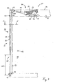
- the box body 10 of a commercial vehicle is preferably with two lateral loading walls 11; Equipped 11.1, 11.2, each as a two-leaf side wall 12; 12.1, 12.2 are designed, which in turn each consist of a lifting wall 13; 13.1, 13.2 and a flap wall 14 is formed.
- the box assembly 10 consists essentially of a box roof 15, a box bottom 16 and the two-leaf side walls 12; 12.1, 12.2 and at least at the corners of the box body 10 of vertical, the box roof 15 with the box bottom 16 connecting vertical stanchions 17.
- the aforementioned parts define a cargo space 18th
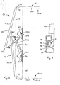
- the flap wall 14 is hinged in the region of the box bottom 16 and is there about a horizontal pivot axis 19 in a vertical pivot plane, for example, from its in FIG. 3 shown closing position 20 in an in FIG. 2 shown opening position 21 swung out, preferably by about 180 °.
- the lifting wall 13; 13.1; 13.2 can be based on the in FIG. 3 shown closed position rotatably to serve as a support and guide element 29, stationary arranged support and guide roller 30 via an in FIG. 1 shown intermediate position 45 in an in FIG. 2 respectively.
- FIG. 4 shown opening position 23, 24 are swung up.
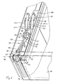
- link chain 26 is fixed with its one end to a receptacle. It is understood that instead of a link chain 26, a rope or the like can be used. As in particular from FIG. 5 it can be seen, the link chain 26 is in the closed state of the side wall 12 in a Runge recess 76 of the stanchion 17 and is covered by edging profiles 79 of the lifting wall 13 and not shown corresponding enclosure profiles of the flap wall 14 in the closed state and is therefore not from the outside in the closed position visible, noticeable.
- the link chain 26 extends with an inner chain portion 77 upwards and is arranged at a in the region of the lateral edge of the box roof 15 and about a parallel to the pivot axis 19 rotatable pulley 27, which is designed here as a sprocket. From there, the link chain 26 runs with its outer chain part 78 along the lifting wall 13, at the, in FIG. 3 shown closed position 22 lower end 37, the other end of the link chain 26 is also attached to a receptacle.
- the lifting wall 13 is supported on an inner side constantly on the support and guide roller 30 from whose axis of rotation 47 coincides in the embodiment with the axis of rotation 46 of the guide roller 27 and which is arranged laterally next to the guide roller 27 ( FIG. 6 ).
- the support and guide roller 30 is provided with at least one radially outwardly extending circumferential guide collar 81 for lateral guidance of the lifting wall 13; 13.1, 13.2 provided.
- two such support and guide rollers 30 are provided per side wall, which are arranged in a width of the lifting wall 13 corresponding distance from each other and each have a guide collar 81 at their ends laterally outwardly extending ends.
- the distance 28 of the point of attack for the traction means 25 on the flap wall 14 of the pivot axis 19 is selected such that when the pivoted in its open position 21 folding wall 14, the lifting wall 13; 13.1, 13.2 completely and without a supernatant in an open position 23, 24 is swung up, so they do not tower over the width of the box body 10 in the roof area 59 laterally and consequently not when loading and / or unloading of cargo, in particular by forklift , can not be damaged, so that the parts connected to the lifting wall are not damaged in this way.
- a handlebar 31 extending above the loading space 18; 31.1, 31.2 arranged.
- This handlebar 31; 31.1, 31.2 is about a first pivot axis 32 and handlebar axis 73.1, 73.2 of a at one of its ends 33 in the roof area 59 fixedly arranged first hinge 34; 34.1, 34.2 articulated freely pivotable and is also about a second pivot axis 35 of a arranged at its other end 36 and hinged to the lifting wall 13 in the region of its closed position in the upper end 38 38 second pivot joint 41 also pivotally.
- the joints 34; 34.1, 34.2 and 41 are preferably each as a hinge with a parallel to each other arranged rotational axis designed, each perpendicular to a vertical pivot plane of the lifting wall 13; 13.1, 13.2 can be arranged.
- the first, lower hinge 34; 34.1, 34.2 is part of a in the roof area 59, preferably on a mounting rail 80, during the pivotal movement of the arm 31 stationary, preferably releasably secured Umlenkgephases 60, which is designed in the embodiment with two parallel, vertically upwardly extending legs 61.1 and 62.2 (see especially FIG. 6 ).
- the first pivot axis 32; 73.1, 73.2 of the fixedly arranged first articulation 34; 34.1, 34.2 and the second pivot axis 35 of the articulated with the lifting wall 13 second articulation 41 of the handlebar 31; 31.1, 31.2 are arranged at a distance 43 from each other, here about half of the height 44 of the lifting wall 13; 13.1, 13.2 corresponds.
- FIG. 3 shown closed position 22 to a in FIG. 2 or in FIG. 4 shown open position 23, 24 to pivot high, in which the lifting wall 13; 13.1, 13.2 completely over the roof 15 and without lateral projection on the vertical alignment of the box body 10 can be pivoted upwards.
- variable adjustment of the distance 43 of the length of the handlebar 31; 31.1, 31.2 includes this in the shown Embodiment two telescopically guided into each other profile parts, namely a profile bar 49 and a profile tube 50 whose inner contour is designed to match the outer contour of the profile bar 49, so that the profile bar 49 in the longitudinal direction of the tube axis of the profile tube 50 in the profile tube 50 is displaceable.
- both the profile tube 50 and the profile bar guided therein 49 in the longitudinal direction of the handlebar 31 spaced in a row of holes arranged through holes, through which one or more locking pins 75 for fixing the profile bar 49 on the profile tube 50 in the desired distance length can be pushed.
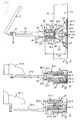
- Their respective first end 54.1 engages at a first distance 52 from the first pivot axis 32; 73.1, 73.2 of the handlebar 31; 31.1, 31.2 on a fastening means connected thereto, here in the form of a fastening bolt, the or with the handlebar 31; 31.1, 31.2 about the first pivot axis 32; 73.1, 73.2 is pivotable when the handlebar 31; 31.1, 31.2 about the pivot axis 32; 73.1, 73.2 is pivoted.
- the respective second end 54.2 of the tension springs 53; 53.1 to 53.4 engages at a second distance 57 from the first pivot axis 32; 73.1, 73.2 of the handlebar 31; 31.1, 31.2 at a spring engagement point 58; 58.1 to 58.5, which is fixedly connected to the roof area 59.
- the second distance 57 in the embodiment shown is smaller than the first distance 52.
- the spring engagement points 58; 58.1 to 58.5 are here designed as hinges or axes of rotation, in the embodiment for a suspension 63; 63.1, 63.2 for the springs 53.1 to 53.4, whereby the travel of the springs is advantageously extended.
- the suspension 63; 63.1, 63.2 has in the region of its one end in the vertical pivoting plane of the handlebar 31; 31.1, 31.2 extending fastening bolt, which serves as a fastening means for the respective second ends 54.2 of the tension springs 53.1 to 53.4, as in particular from FIG. 7 seen.
- the suspension 63; 63.1, 63.2 is a parallel to the first pivot axis 32, 73.1, 73.2 of the handlebar 31; 31.1, 31.2 at a distance 61 arranged rotation axis 66 rotatably, which is rotatably mounted in the illustrated embodiment at the middle of here a total of 5 spring engagement points 58.1 to 58.5.
- the suspension 63; 63.1, 63.2 may also be omitted if appropriate, in which case the springs 53.1 to 53.4 can be optionally fixed directly to the spring engagement points 58.1 to 58.5.
- the spring engagement points 58.1 to 58.5 are preferably formed as a hinge or pivot point for the springs 53.1 to 53.4. It is further understood that, if necessary, only a single tension spring can be used instead of four tension springs.
- the suspension 63; 63.1, 63.2 designed with an elongated profile 64 having a first attachment point 65.1 for a first spring 53.1 and having a second attachment point 65.2 for a second spring 53.2, wherein the Attachment points are here formed at the transverse to the elongated profile 64 extending fastening bolts, and wherein the axis of rotation 66 of the suspension 63 between the first spring 53.1 and the second spring 53.2 is arranged.
- the suspension 63; 63.1, 63.2 is designed in the embodiment as an on either side of the axis of rotation 66 extending elongate profile 64, so with the axis of rotation 66 extending in opposite directions profile legs, so that a favorable support of the suspension 63 on both sides of the axis of rotation 66 and on both sides of the elongated Profile 64 arranged tension springs 53.1 and 53.2 is possible.
- the link arm 31 To the handlebar side attachment of the springs 53.1 to 53.4 is on the link arm 31; 31.1, 31.2 designed as a sliding part 67 fastening body 66 is provided, on which the springs 53.1 to 53.4 attack and which is intended to adjust different spring voltages can.
- the springs 53.1 to 53.4 engage approximately parallel to the first pivot axis 32; 73.1, 73.2 of the handlebar 31; 31.1, 31.2 in each case laterally outwardly extending fastening bolts to fastening points 65.1 to 65.4, wherein two springs are arranged on sides facing away from each other of the handlebar 31 ( FIGS. 8 and 9 ).
- the sliding part 67 is on the handlebar 31; 31.1, 31.2 arranged along the same slidably.
- the sliding part 67 has a transversely to the handlebar axis 32, 73.1, 73.2 extending leg 68, which in the embodiment with a along the handlebar 31; 31.1, 31.2 extending internal thread 69 is formed, in which a threaded male bolt 70 designed with a matching external thread 71 is screwed, whose protruding from the leg 68 on its other side end is supported on a transverse leg 72 of the handlebar 31 (see in particular FIG. 6 ).
- the distance of the sliding part 67 and thus the distance of the fixing bolts used for fastening relative to the first pivot axis 32; 73.1, 73.2 of the handlebar 31; 31.1, 31.2 are set differently, whereby different spring voltages can be adjusted.
- the box body 10 can preferably be provided at its opposite longitudinal end faces in each case with a two-winged side wall 12.1 and 12.2.
- the side walls 12.1 and 12.2 are preferably made of substantially equal parts, as the side wall 12 according to the FIGS. 1 to 3 and 5 to 7, with the exception of the handlebar constructions ( FIGS. 8 and 9 ).
- a first link 31.1 of a first side wall 12.1 can be pivotably mounted about a pivot axis 74.1 about a pivot axis 74.1 in the roof area 59 of the box structure 10, wherein a second link 31.2 of a second side wall 12.2 is also fixed in the roof area 59 of the box structure 10 arranged second link shaft 73.2 may be pivotally mounted about a rotational axis 74.2, wherein the second link 31.2 is arranged offset in the direction of the axis of rotation 74.1 of the first link 31.1 transversely to the first link 31.1.
- these handlebar constructions differ essentially by different attachment means, here fastening bolts, to which the second ends of the springs 53.1 to 53.4 are fastened, and also by the position and arrangement of the links 31.1, 31.2 relative to their Swivel axles 73.1 and 73.2, while the springs 53.1 to 53.4, the suspensions 63.1, 63.2 and the deflection housing 60 are designed with their vertically upstanding legs 62.1 and 62.2 each equal.
- the opening of the double-winged side wall 12, starting from the in FIG. 3 Shown closed position shown, in which therefore the lifting wall 13 in its closed position 22 and in which the flap wall 14 is in its closed position 20.
- the flap wall 14 is preferably pivoted manually in the direction of the arrow 82 about its pivot axis 19 down.
- flexible traction means 25 causes the lifting wall 13 first enters into an open position corresponding intermediate position 45, as shown FIG. 1 seen.
- the lifting wall 13 by the on her in the closed position 22, the upper end 38 is guided over the articulated arm 41 on the link 31, which is pivoted in the course of the pivoting of the lifting wall 13 about its also designated as a pivot axis 32 link axis.
- the lifting wall 13 is guided and supported by the support and guide roller, to which it preferably constantly rests under a sliding rotary motion.
- the lifting wall 13 is completely pivoted on the loading space 18 vertically upwardly bound box roof 15, to a position in which the lifting wall 13 no longer protrudes laterally beyond the vertical alignment of the box body 10, as in FIG. 2 shown.
- the tension springs 53.1 to 53.4 are provided as a force storage 51.
- the springs 53 are arranged and fixed so that they are in the in FIG. 3 shown closed position 22 of the lifting wall 13 a whose opening movement assisting torque (arrow 83) exert on the handlebar 31, while in the in FIG. 2 shown opening position 23 of the lifting wall 13 on the handlebar 31 in the direction of the arrow 84, that is opposite acting torque exert.
Landscapes
- Engineering & Computer Science (AREA)
- Mechanical Engineering (AREA)
- Fittings On The Vehicle Exterior For Carrying Loads, And Devices For Holding Or Mounting Articles (AREA)
- Closing Of Containers (AREA)
- Buildings Adapted To Withstand Abnormal External Influences (AREA)
- Finger-Pressure Massage (AREA)
- Cartons (AREA)
- Conveying And Assembling Of Building Elements In Situ (AREA)
- Toys (AREA)
- Closing And Opening Devices For Wings, And Checks For Wings (AREA)
Claims (19)
- Structure de caisse (10), en particulier pour véhicules utilitaires, comportant un fond (16), un toit (15), un espace de chargement (18) et au moins une paroi latérale à deux battants (12 ; 12.1, 12.2) qui comporte une paroi rabattable (14) articulée au niveau du fond (16) et pouvant être pivotée, autour d'un axe de pivotement (19), de sa position fermée (20) à une position ouverte (21), et comportant une paroi élévatrice (13 ; 13.1, 13.2), pouvant être pivotée vers le haut dans une position ouverte (23, 24) dans la zone de toit (59), paroi élévatrice qui est rattachée à la paroi rabattable (14) par au moins un moyen de traction flexible (25), moyen de traction qui est enroulé autour d'une poulie de renvoi (27) disposée dans la zone de toit (59) et est en prise avec la paroi rabattable (14), à distance (28) de l'axe d'articulation (19), de telle sorte que, lors du rabattement de la paroi rabattable (14), la paroi élévatrice (13 ; 13.1, 13.2) regagne sa position ouverte (23), et un élément d'appui et de guidage (29) étant disposé dans la zone de toit (59), élément sur lequel repose la paroi élévatrice (13 ; 13.1, 13.2) lors du pivotement de sa position fermée (22) à sa position ouverte (23) et inversement, avec décalage simultané par rapport à l'élément d'appui et de guidage (29), et comportant une bielle (31 ; 31.1, 31.2), pour la paroi élévatrice (13 ; 13.1, 13.2), s'étendant au-dessus de l'espace de chargement,
la bielle (31 ; 31.1, 31.2) étant articulée de manière à pouvoir pivoter librement autour d'un premier axe de pivotement (32 ; 73.1, 73.2) d'une première articulation (34 ; 34.1, 34.2) agencée de manière fixe sur l'une de ses extrémités (33) dans la zone de toit (59) et étant articulée de manière à pouvoir pivoter autour d'un second axe de pivotement (35) d'une seconde articulation (41) agencée sur son autre extrémité (36) et reliée à la paroi élévatrice (13 ; 13.1, 13.2) au niveau de son extrémité supérieure (38) dans la position fermée (22), caractérisée en ce que l'on a prévu des moyens (48) de réglage variable de l'écartement (43) entre la première articulation (34 ; 34.1, 34.2) de la bielle (31 ; 31.1, 31.2) et la seconde articulation (41) de la bielle (31 ; 31.1, 31.2). - Structure de caisse selon la revendication 1, caractérisée en ce qu'on a prévu une bielle unique (31 ; 31.1, 31.2).
- Structure de caisse selon la revendication 1 ou 2, caractérisée en ce que le premier axe de pivotement (32 ; 73.1, 73.2) de la première articulation (34 ; 34.1, 34.2) et le second axe de pivotement (35) de la seconde articulation (41) de la bielle (31 ; 31.1, 31.2) sont disposés à une distance (52) l'un de l'autre qui correspond à environ la moitié de la hauteur (44) de la paroi élévatrice (13 ; 13.1, 13.2).
- Structure de caisse selon l'une quelconque des revendications 1 à 3, caractérisée en ce que la paroi élévatrice (13 ; 13.1 , 13.2) et / ou la bielle (31 ; 31.1, 31.2) surplombent, vers le haut, une arête supérieure (42) du toit (15), au moins dans une position intermédiaire (45) entre la position ouverte (23) et la position fermée (22) de la paroi élévatrice (13 ; 13.1, 13.2).
- Structure de caisse selon l'une quelconque des revendications 1 à 4, caractérisée en ce qu'on a prévu une poulie de renvoi (27) unique pour le moyen de traction (25).
- Structure de caisse selon la revendication 5, caractérisée en ce que l'élément d'appui et de guidage (29) est réalisé sous forme de rouleau d'appui et de guidage (30) qui est disposée dans le sens coaxial par rapport à la poulie de renvoi (27) et de manière fixe au niveau d'une arête latérale du toit (15).
- Structure de caisse selon l'une quelconque des revendications 1 à 6, caractérisée en ce que le moyen de traction (25) est en prise avec la paroi élévatrice (13 ; 13.1, 13.2), au niveau de l'extrémité inférieure (37) de celle-ci.
- Structure de caisse selon l'une quelconque des revendications 1 à 7, caractérisée en ce que la paroi élévatrice (13 ; 13.1, 13.2) repose on permanence sur l'élément d'appui et de guidage (29) lors du pivotement de sa position fermée (22) à sa position ouverte (23) et inversement.
- Structure de caisse selon l'une quelconque des revendications 1 à 8, caractérisée en ce qu'on a prévu au moins un accumulateur d'énergie (51), disposé dans la zone de toit (59), qui est en prise avec la bielle (31 ; 31.1, 31.2) à distance (52) du premier axe de pivotement (32 ; 73.1, 73.2) de telle sorte que le processus de fermeture et / ou le processus d'ouverture de le paroi élévatrice (13 ; 13.1, 13.2) soient soutenus.
- Structure de caisse selon la revendication 9, caractérisée en ce que l'accumulateur d'énergie (51) est un ressort de traction (53 ; 53.1 à 53.4) dont la première extrémité (54.1) est en prise, à une première distance (52) du premier axe de pivotement (32 ; 73.1, 73.2) de la bielle (31 ; 31.1, 31.2), avec un moyen de fixation (86 ; 87.1, 87.2) rattaché à celle-ci, moyen de fixation qui peut pivoter avec la bielle (31 31.1, 31.2) autour du premier axe de pivotement (32), et dont la seconde extrémité (54.2) est en prise, à une seconde distance (57), inférieure à la première distance (52), du premier axe de pivotement (32 ; 73.1, 73.2) de la bielle (31 ; 31.1, 31.2), avec un point d'action du ressort (58 ; 58.1 à 58.5) qui est relié de manière fixe à la zone de toit (59).
- Structure de caisse selon la revendication 10, caractérisée en ce que le point d'action du ressort (58 ; 58.1 à 58.5) est agencé sur un boîtier de renvoi (60) disposé de manière fixe dans la zone de toit (59), à une distance verticale (61), au-dessus du premier axe de pivotement (32 ; 73.1, 73.2) monté sur le boîtier de renvoi (60).
- Structure de caisse selon la revendication 10 ou 11, caractérisée en ce que le point d'action du ressort (58 ; 58.1 à 58.5) est réalisé avec une articulation pour une suspension (63 ; 63.1, 63.2), pouvant tourner autour d'un axe de rotation (66), pour le ressort (53 ; 53.1 à 53.4), suspension sur laquelle est fixée la seconde extrémité (54.2) du ressort de traction (53 ; 53.1 à 53.4).
- Structure de caisse selon la revendication 11 ou 12, caractérisée en ce que, pour compenser les différentes conditions pondérales de la paroi élévatrice (13 ; 13.1, 13.2) et de la paroi rabattable (14), on a prévu plusieurs points d'action du ressort (58 ; 58.1 à 58.5) sur lesquels le ressort de traction (53 ; 53.1 à 53.4) peut être fixé au choix, au moins un point d'action du ressort (58.1 à 58.5) étant disposé perpendiculairement au première axe de pivotement (32), décalé dans le sens horizontal par rapport à un point d'action du ressort adjacent.
- Structure de caisse selon la revendication 12 ou 13, caractérisée en ce que la suspension (63 ; 63.1, 63.2) est réalisée avec un profilé allongé (64) qui comporte un premier point de fixation (65.1) pour un premier ressort (53.1) et qui comporte un second point de fixation (65.2) pour un second ressort (53.2), l'axe de rotation (66) de la suspension (63 ; 63.1, 63.2) étant disposé entre le premier ressort (53.1) et le second ressort (53.2).
- Structure de caisse selon l'une quelconque des revendications 12 à 14, caractérisée en ce que la suspension (63 ; 63.1, 63.2) est réalisée sous la forme d'un profilé (64) s'étendant des deux côtés de l'axe de rotation (66).
- Structure de caisse selon l'une quelconque des revendications 1 à 15, caractérisée en ce qu'un élément de fixation (85) est fixé sur la bielle (31 ; 31.1, 31.2), élément de fixation avec lequel le ressort (53 ; 53.1 à 53.4) est en prise et qui est conçu pour permettre le réglage de différentes tensions de ressort.
- Structure de caisse selon la revendication 16, caractérisée en ce que l'élément de fixation (85) est conçu pour permettre un réglage sans gradations de la tension du ressort.
- Structure de caisse selon la revendication 16 ou 17, caractérisée en ce que l'élément de fixation (85) est réalisé sous la forme d'une pièce coulissante (67) en appui sur la bielle (31 ; 31.1, 31.2) et déplaçable le long de celle-ci, pièce coulissante sur laquelle est fixé un montant (68) avec un filet interne (69) s'étendant le long de la bielle (31 ; 31.1, 31.2), filet interne dans lequel est vissé un boulon fileté (70) avec filet externe (71) dont l'extrémité s'appuie sur un montant transversal (72) de la bielle (31 ; 31.1, 31.2).
- Structure de caisse selon l'une quelconque des revendications 1 à 18, caractérisée en ce qu'elle comporte une paroi latérale à deux battants (12.1, 12.2) sur chacun de ses deux fronts latéraux, une première bielle (31.1) d'une première paroi latérale (12.1) étant montée de façon à pouvoir pivoter autour d'un premier axe de bielle (73.1) agencé de manière fixe dans la zone de toit (59) de la structure de caisse (10) et une seconde bielle (31.2) d'une seconde paroi latérale (12.2) étant montée de façon à pouvoir pivoter autour d'un second axe de bielle (73.2) agencé de manière fixe dans la zone de toit (59) de la structure de caisse (10), la seconde bielle (31.2) étant agencée en décalage, perpendiculairement à la première bielle (31.1), en direction de l'axe de rotation (74.1) de la première bielle de telle sorte que les deux bielles (31.1, 31.2) se croisent lorsque les parois élévatrices (13.1, 1.2) sont entièrement pivotées vers le haut, au-dessus du toit (15), et se chevauchent au niveau de leurs extrémités supérieures (38.1, 38.2) dans leurs positions fermées.
Priority Applications (2)
| Application Number | Priority Date | Filing Date | Title |
|---|---|---|---|
| PL04018787T PL1516763T3 (pl) | 2003-09-19 | 2004-08-07 | Nadwozie skrzyniowe |
| DE202004021073U DE202004021073U1 (de) | 2003-09-19 | 2004-08-07 | Kastenaufbau |
Applications Claiming Priority (2)
| Application Number | Priority Date | Filing Date | Title |
|---|---|---|---|
| DE10343915A DE10343915B4 (de) | 2003-09-19 | 2003-09-19 | Kastenaufbau |
| DE10343915 | 2003-09-19 |
Publications (3)
| Publication Number | Publication Date |
|---|---|
| EP1516763A2 EP1516763A2 (fr) | 2005-03-23 |
| EP1516763A3 EP1516763A3 (fr) | 2007-01-17 |
| EP1516763B1 true EP1516763B1 (fr) | 2009-11-04 |
Family
ID=34177894
Family Applications (1)
| Application Number | Title | Priority Date | Filing Date |
|---|---|---|---|
| EP04018787A Expired - Lifetime EP1516763B1 (fr) | 2003-09-19 | 2004-08-07 | Structure de caisse |
Country Status (4)
| Country | Link |
|---|---|
| EP (1) | EP1516763B1 (fr) |
| AT (1) | ATE447502T1 (fr) |
| DE (3) | DE10343915B4 (fr) |
| PL (1) | PL1516763T3 (fr) |
Families Citing this family (2)
| Publication number | Priority date | Publication date | Assignee | Title |
|---|---|---|---|---|
| DE102006053523B3 (de) * | 2006-11-07 | 2008-01-31 | Orten Karlsdorf-Neuthard Gmbh & Co. Kg | Vorrichtung zum Überführen einer Wand eines Transportbehälters zwischen einer Schliessstellung und einer Offenstellung und Transportbehälter |
| AT508096B1 (de) * | 2009-04-09 | 2011-01-15 | Strasser Johann Sen | Vorrichtung zum überführen einer seitenwand eines transportbehälters |
Family Cites Families (12)
| Publication number | Priority date | Publication date | Assignee | Title |
|---|---|---|---|---|
| DE7707180U1 (de) * | 1977-03-09 | 1977-08-11 | Heinz Boese Kg, 5779 Reiste | Aufbau für einen Lastkraftwagen oder Anhänger mit Ladebordwänden |
| DE2813593C2 (de) * | 1978-03-30 | 1982-02-11 | Franz 5778 Meschede Ewers | Seitenwand für Kastenaufbauten von Lastkraftwagen |
| DE2931111C2 (de) * | 1979-07-31 | 1984-04-05 | Diamoil S.A., 1207 Genève | Fahrzeugaufbau mit in horizontaler Richtung unterteilten Seitenwänden |
| DE3121690A1 (de) * | 1981-06-01 | 1982-12-16 | F.X. Kögel GmbH & Co Fahrzeugwerke, 7900 Ulm | "geteilte ladebordwand" |
| DE3219505A1 (de) * | 1982-05-25 | 1983-12-01 | F.X. Kögel GmbH & Co Fahrzeugwerke, 7900 Ulm | Ladebordwand fuer gedeckte kraftfahrzeug-aufbauten |
| EP0116722B1 (fr) * | 1983-01-26 | 1987-04-15 | TREFA - Jürgen Nichts Karosserie- und Fahrzeugtechnik GmbH & Co KG | Dispositif pour l'ouverture ou la fermeture simultanée des parties inférieure et supérieure d'une ridelle |
| DE3525628A1 (de) * | 1985-07-18 | 1987-01-22 | Gross Aluminium Gmbh | Klappwand, insbesondere fuer fahrzeugaufbauten |
| DE4033691C2 (de) * | 1990-10-23 | 1999-03-04 | Georg Maierbacher | Seitenwandanordnung für gedeckte Kastenaufbauten |
| DE4427518C1 (de) * | 1994-08-03 | 1996-01-18 | Georg Maierbacher | Fahrzeugaufbau, insbesondere für Lastkraftwagen und Anhänger, mit einer öffenbaren Seitenwand |
| DE59502117D1 (de) * | 1995-06-28 | 1998-06-10 | Keppler Gmbh Fahrzeugbau | Kastenaufbau |
| AU711371B2 (en) * | 1996-03-21 | 1999-10-14 | Johann Strasser | Side wall for the body of a vehicle |
| DE19839839B4 (de) * | 1998-09-02 | 2008-09-04 | Georg Ewers | Seitenwand eines Fahrzeugs oder Anhängers |
-
2003
- 2003-09-19 DE DE10343915A patent/DE10343915B4/de not_active Expired - Fee Related
- 2003-09-19 DE DE20321820U patent/DE20321820U1/de not_active Expired - Lifetime
-
2004
- 2004-08-07 EP EP04018787A patent/EP1516763B1/fr not_active Expired - Lifetime
- 2004-08-07 PL PL04018787T patent/PL1516763T3/pl unknown
- 2004-08-07 DE DE502004010316T patent/DE502004010316D1/de not_active Expired - Lifetime
- 2004-08-07 AT AT04018787T patent/ATE447502T1/de active
Also Published As
| Publication number | Publication date |
|---|---|
| EP1516763A3 (fr) | 2007-01-17 |
| EP1516763A2 (fr) | 2005-03-23 |
| DE10343915A1 (de) | 2005-05-04 |
| DE502004010316D1 (de) | 2009-12-17 |
| PL1516763T3 (pl) | 2010-04-30 |
| ATE447502T1 (de) | 2009-11-15 |
| DE10343915B4 (de) | 2010-11-25 |
| DE20321820U1 (de) | 2010-10-28 |
Similar Documents
| Publication | Publication Date | Title |
|---|---|---|
| DE112006001492B4 (de) | Längsträgerprofil und Verdeckgestell für einen Planenaufbau | |
| EP3235668A1 (fr) | Superstructure bâchée | |
| DE69702305T2 (de) | Öffnungsvorrichtung für einen mit einer plane ausgerüsteten behälter | |
| DE102008028633B4 (de) | Antriebsanordnung für einen Schwenkflügel | |
| CH645580A5 (de) | Lastkraftwagen mit einer ladepritsche und einem aufbau. | |
| EP1955932A2 (fr) | Mécanisme de fermeture pour une structure de véhicule | |
| EP1516763B1 (fr) | Structure de caisse | |
| EP2676824A2 (fr) | Structure pour le transports de biens | |
| EP1354790A1 (fr) | Rancher pliant avec dispositif de verrouillage | |
| WO2007124802A1 (fr) | Système de garage pour véhicules à moteur | |
| DE2931111C2 (de) | Fahrzeugaufbau mit in horizontaler Richtung unterteilten Seitenwänden | |
| EP1004736A2 (fr) | Véhicule automobile avec pièce de carrosserie articulée à une carrosserie par au moins une charnière | |
| DE102008018331A1 (de) | Hubflügeltür für eine Fahrzeugkarosserie | |
| DE4033691C2 (de) | Seitenwandanordnung für gedeckte Kastenaufbauten | |
| AT522700B1 (de) | Absenkbare Transportguthaltevorrichtung, Montagesatz und -verfahren | |
| EP0785330B1 (fr) | Charnière de rayon arrière pour véhicules automobiles | |
| WO2010086318A1 (fr) | Ensemble ferrure pour coupole lumineuse | |
| DE4427518C1 (de) | Fahrzeugaufbau, insbesondere für Lastkraftwagen und Anhänger, mit einer öffenbaren Seitenwand | |
| DE102005016158B3 (de) | Verdeckgestell für einen Planenaufbau | |
| DE202004021073U1 (de) | Kastenaufbau | |
| WO2015128468A1 (fr) | Plaque pliante | |
| DE102014013788B4 (de) | Verdeckgestell für eine zusammenschiebbare Plane | |
| EP0882612B1 (fr) | Bâche coulissant pour carrosseries de véhicule et conteneurs | |
| DE102017109780B3 (de) | Aufbau zum Befördern von Gütern | |
| EP1809844A1 (fr) | Dispositif d'entrainement de porte tournante, armature associee et porte tournante equipee d'un tel dispositif |
Legal Events
| Date | Code | Title | Description |
|---|---|---|---|
| PUAI | Public reference made under article 153(3) epc to a published international application that has entered the european phase |
Free format text: ORIGINAL CODE: 0009012 |
|
| AK | Designated contracting states |
Kind code of ref document: A2 Designated state(s): AT BE BG CH CY CZ DE DK EE ES FI FR GB GR HU IE IT LI LU MC NL PL PT RO SE SI SK TR |
|
| AX | Request for extension of the european patent |
Extension state: AL HR LT LV MK |
|
| 19U | Interruption of proceedings before grant |
Effective date: 20050502 |
|
| 19W | Proceedings resumed before grant after interruption of proceedings |
Effective date: 20051201 |
|
| RAP1 | Party data changed (applicant data changed or rights of an application transferred) |
Owner name: TSE TRAILER-SYSTEM-ENGINEERING GMBH & CO. KG |
|
| PUAL | Search report despatched |
Free format text: ORIGINAL CODE: 0009013 |
|
| AK | Designated contracting states |
Kind code of ref document: A3 Designated state(s): AT BE BG CH CY CZ DE DK EE ES FI FR GB GR HU IE IT LI LU MC NL PL PT RO SE SI SK TR |
|
| AX | Request for extension of the european patent |
Extension state: AL HR LT LV MK |
|
| 17P | Request for examination filed |
Effective date: 20070717 |
|
| AKX | Designation fees paid |
Designated state(s): AT BE BG CH CY CZ DE DK EE ES FI FR GB GR HU IE IT LI LU MC NL PL PT RO SE SI SK TR |
|
| 17Q | First examination report despatched |
Effective date: 20080108 |
|
| GRAP | Despatch of communication of intention to grant a patent |
Free format text: ORIGINAL CODE: EPIDOSNIGR1 |
|
| RAP1 | Party data changed (applicant data changed or rights of an application transferred) |
Owner name: ORTEN, ROBERT ERICH |
|
| GRAS | Grant fee paid |
Free format text: ORIGINAL CODE: EPIDOSNIGR3 |
|
| GRAA | (expected) grant |
Free format text: ORIGINAL CODE: 0009210 |
|
| AK | Designated contracting states |
Kind code of ref document: B1 Designated state(s): AT BE BG CH CY CZ DE DK EE ES FI FR GB GR HU IE IT LI LU MC NL PL PT RO SE SI SK TR |
|
| REG | Reference to a national code |
Ref country code: GB Ref legal event code: FG4D Free format text: NOT ENGLISH |
|
| REG | Reference to a national code |
Ref country code: CH Ref legal event code: EP |
|
| REG | Reference to a national code |
Ref country code: IE Ref legal event code: FG4D |
|
| REF | Corresponds to: |
Ref document number: 502004010316 Country of ref document: DE Date of ref document: 20091217 Kind code of ref document: P |
|
| REG | Reference to a national code |
Ref country code: CH Ref legal event code: NV Representative=s name: TROESCH SCHEIDEGGER WERNER AG |
|
| PG25 | Lapsed in a contracting state [announced via postgrant information from national office to epo] |
Ref country code: FI Free format text: LAPSE BECAUSE OF FAILURE TO SUBMIT A TRANSLATION OF THE DESCRIPTION OR TO PAY THE FEE WITHIN THE PRESCRIBED TIME-LIMIT Effective date: 20091104 Ref country code: ES Free format text: LAPSE BECAUSE OF FAILURE TO SUBMIT A TRANSLATION OF THE DESCRIPTION OR TO PAY THE FEE WITHIN THE PRESCRIBED TIME-LIMIT Effective date: 20100215 Ref country code: PT Free format text: LAPSE BECAUSE OF FAILURE TO SUBMIT A TRANSLATION OF THE DESCRIPTION OR TO PAY THE FEE WITHIN THE PRESCRIBED TIME-LIMIT Effective date: 20100304 Ref country code: SE Free format text: LAPSE BECAUSE OF FAILURE TO SUBMIT A TRANSLATION OF THE DESCRIPTION OR TO PAY THE FEE WITHIN THE PRESCRIBED TIME-LIMIT Effective date: 20091104 |
|
| REG | Reference to a national code |
Ref country code: PL Ref legal event code: T3 |
|
| REG | Reference to a national code |
Ref country code: IE Ref legal event code: FD4D |
|
| PG25 | Lapsed in a contracting state [announced via postgrant information from national office to epo] |
Ref country code: CY Free format text: LAPSE BECAUSE OF FAILURE TO SUBMIT A TRANSLATION OF THE DESCRIPTION OR TO PAY THE FEE WITHIN THE PRESCRIBED TIME-LIMIT Effective date: 20091104 Ref country code: SI Free format text: LAPSE BECAUSE OF FAILURE TO SUBMIT A TRANSLATION OF THE DESCRIPTION OR TO PAY THE FEE WITHIN THE PRESCRIBED TIME-LIMIT Effective date: 20091104 |
|
| PG25 | Lapsed in a contracting state [announced via postgrant information from national office to epo] |
Ref country code: IE Free format text: LAPSE BECAUSE OF FAILURE TO SUBMIT A TRANSLATION OF THE DESCRIPTION OR TO PAY THE FEE WITHIN THE PRESCRIBED TIME-LIMIT Effective date: 20091104 Ref country code: BG Free format text: LAPSE BECAUSE OF FAILURE TO SUBMIT A TRANSLATION OF THE DESCRIPTION OR TO PAY THE FEE WITHIN THE PRESCRIBED TIME-LIMIT Effective date: 20100204 Ref country code: DK Free format text: LAPSE BECAUSE OF FAILURE TO SUBMIT A TRANSLATION OF THE DESCRIPTION OR TO PAY THE FEE WITHIN THE PRESCRIBED TIME-LIMIT Effective date: 20091104 Ref country code: EE Free format text: LAPSE BECAUSE OF FAILURE TO SUBMIT A TRANSLATION OF THE DESCRIPTION OR TO PAY THE FEE WITHIN THE PRESCRIBED TIME-LIMIT Effective date: 20091104 Ref country code: RO Free format text: LAPSE BECAUSE OF FAILURE TO SUBMIT A TRANSLATION OF THE DESCRIPTION OR TO PAY THE FEE WITHIN THE PRESCRIBED TIME-LIMIT Effective date: 20091104 |
|
| PG25 | Lapsed in a contracting state [announced via postgrant information from national office to epo] |
Ref country code: SK Free format text: LAPSE BECAUSE OF FAILURE TO SUBMIT A TRANSLATION OF THE DESCRIPTION OR TO PAY THE FEE WITHIN THE PRESCRIBED TIME-LIMIT Effective date: 20091104 |
|
| PLBE | No opposition filed within time limit |
Free format text: ORIGINAL CODE: 0009261 |
|
| STAA | Information on the status of an ep patent application or granted ep patent |
Free format text: STATUS: NO OPPOSITION FILED WITHIN TIME LIMIT |
|
| 26N | No opposition filed |
Effective date: 20100805 |
|
| PG25 | Lapsed in a contracting state [announced via postgrant information from national office to epo] |
Ref country code: GR Free format text: LAPSE BECAUSE OF FAILURE TO SUBMIT A TRANSLATION OF THE DESCRIPTION OR TO PAY THE FEE WITHIN THE PRESCRIBED TIME-LIMIT Effective date: 20100205 |
|
| PGFP | Annual fee paid to national office [announced via postgrant information from national office to epo] |
Ref country code: CZ Payment date: 20100930 Year of fee payment: 7 |
|
| PG25 | Lapsed in a contracting state [announced via postgrant information from national office to epo] |
Ref country code: IT Free format text: LAPSE BECAUSE OF FAILURE TO SUBMIT A TRANSLATION OF THE DESCRIPTION OR TO PAY THE FEE WITHIN THE PRESCRIBED TIME-LIMIT Effective date: 20091104 Ref country code: MC Free format text: LAPSE BECAUSE OF NON-PAYMENT OF DUE FEES Effective date: 20100831 |
|
| PGFP | Annual fee paid to national office [announced via postgrant information from national office to epo] |
Ref country code: BE Payment date: 20101011 Year of fee payment: 7 |
|
| GBPC | Gb: european patent ceased through non-payment of renewal fee |
Effective date: 20100807 |
|
| REG | Reference to a national code |
Ref country code: FR Ref legal event code: ST Effective date: 20110502 |
|
| PG25 | Lapsed in a contracting state [announced via postgrant information from national office to epo] |
Ref country code: FR Free format text: LAPSE BECAUSE OF NON-PAYMENT OF DUE FEES Effective date: 20100831 |
|
| PG25 | Lapsed in a contracting state [announced via postgrant information from national office to epo] |
Ref country code: GB Free format text: LAPSE BECAUSE OF NON-PAYMENT OF DUE FEES Effective date: 20100807 |
|
| BERE | Be: lapsed |
Owner name: ORTEN, ROBERT ERICH Effective date: 20110831 |
|
| PG25 | Lapsed in a contracting state [announced via postgrant information from national office to epo] |
Ref country code: CZ Free format text: LAPSE BECAUSE OF NON-PAYMENT OF DUE FEES Effective date: 20110807 |
|
| PG25 | Lapsed in a contracting state [announced via postgrant information from national office to epo] |
Ref country code: BE Free format text: LAPSE BECAUSE OF NON-PAYMENT OF DUE FEES Effective date: 20110831 |
|
| PG25 | Lapsed in a contracting state [announced via postgrant information from national office to epo] |
Ref country code: HU Free format text: LAPSE BECAUSE OF FAILURE TO SUBMIT A TRANSLATION OF THE DESCRIPTION OR TO PAY THE FEE WITHIN THE PRESCRIBED TIME-LIMIT Effective date: 20100505 |
|
| PGFP | Annual fee paid to national office [announced via postgrant information from national office to epo] |
Ref country code: LU Payment date: 20120824 Year of fee payment: 9 |
|
| PG25 | Lapsed in a contracting state [announced via postgrant information from national office to epo] |
Ref country code: TR Free format text: LAPSE BECAUSE OF FAILURE TO SUBMIT A TRANSLATION OF THE DESCRIPTION OR TO PAY THE FEE WITHIN THE PRESCRIBED TIME-LIMIT Effective date: 20091104 |
|
| PGFP | Annual fee paid to national office [announced via postgrant information from national office to epo] |
Ref country code: NL Payment date: 20120824 Year of fee payment: 9 |
|
| REG | Reference to a national code |
Ref country code: NL Ref legal event code: V1 Effective date: 20140301 |
|
| PG25 | Lapsed in a contracting state [announced via postgrant information from national office to epo] |
Ref country code: NL Free format text: LAPSE BECAUSE OF NON-PAYMENT OF DUE FEES Effective date: 20140301 |
|
| PG25 | Lapsed in a contracting state [announced via postgrant information from national office to epo] |
Ref country code: LU Free format text: LAPSE BECAUSE OF NON-PAYMENT OF DUE FEES Effective date: 20130807 |
|
| PGFP | Annual fee paid to national office [announced via postgrant information from national office to epo] |
Ref country code: PL Payment date: 20150807 Year of fee payment: 12 |
|
| PGFP | Annual fee paid to national office [announced via postgrant information from national office to epo] |
Ref country code: CH Payment date: 20160824 Year of fee payment: 13 |
|
| PGFP | Annual fee paid to national office [announced via postgrant information from national office to epo] |
Ref country code: DE Payment date: 20170921 Year of fee payment: 14 |
|
| PGFP | Annual fee paid to national office [announced via postgrant information from national office to epo] |
Ref country code: AT Payment date: 20170830 Year of fee payment: 14 |
|
| PG25 | Lapsed in a contracting state [announced via postgrant information from national office to epo] |
Ref country code: PL Free format text: LAPSE BECAUSE OF NON-PAYMENT OF DUE FEES Effective date: 20160807 |
|
| REG | Reference to a national code |
Ref country code: CH Ref legal event code: PL |
|
| PG25 | Lapsed in a contracting state [announced via postgrant information from national office to epo] |
Ref country code: LI Free format text: LAPSE BECAUSE OF NON-PAYMENT OF DUE FEES Effective date: 20170831 Ref country code: CH Free format text: LAPSE BECAUSE OF NON-PAYMENT OF DUE FEES Effective date: 20170831 |
|
| REG | Reference to a national code |
Ref country code: DE Ref legal event code: R119 Ref document number: 502004010316 Country of ref document: DE |
|
| REG | Reference to a national code |
Ref country code: AT Ref legal event code: MM01 Ref document number: 447502 Country of ref document: AT Kind code of ref document: T Effective date: 20180807 |
|
| PG25 | Lapsed in a contracting state [announced via postgrant information from national office to epo] |
Ref country code: AT Free format text: LAPSE BECAUSE OF NON-PAYMENT OF DUE FEES Effective date: 20180807 |
|
| PG25 | Lapsed in a contracting state [announced via postgrant information from national office to epo] |
Ref country code: DE Free format text: LAPSE BECAUSE OF NON-PAYMENT OF DUE FEES Effective date: 20190301 |