EP1516763B1 - Body structure - Google Patents
Body structure Download PDFInfo
- Publication number
- EP1516763B1 EP1516763B1 EP04018787A EP04018787A EP1516763B1 EP 1516763 B1 EP1516763 B1 EP 1516763B1 EP 04018787 A EP04018787 A EP 04018787A EP 04018787 A EP04018787 A EP 04018787A EP 1516763 B1 EP1516763 B1 EP 1516763B1
- Authority
- EP
- European Patent Office
- Prior art keywords
- wall
- guide
- box body
- spring
- body according
- Prior art date
- Legal status (The legal status is an assumption and is not a legal conclusion. Google has not performed a legal analysis and makes no representation as to the accuracy of the status listed.)
- Not-in-force
Links
Images


Classifications
-
- B—PERFORMING OPERATIONS; TRANSPORTING
- B60—VEHICLES IN GENERAL
- B60J—WINDOWS, WINDSCREENS, NON-FIXED ROOFS, DOORS, OR SIMILAR DEVICES FOR VEHICLES; REMOVABLE EXTERNAL PROTECTIVE COVERINGS SPECIALLY ADAPTED FOR VEHICLES
- B60J5/00—Doors
- B60J5/04—Doors arranged at the vehicle sides
- B60J5/0497—Doors arranged at the vehicle sides for load transporting vehicles or public transport, e.g. lorries, trucks, buses
- B60J5/0498—Doors arranged at the vehicle sides for load transporting vehicles or public transport, e.g. lorries, trucks, buses with rigid panels pivoting about a horizontal axis
Definitions
- the invention relates to a box body, in particular for commercial vehicles, with a box bottom, a box roof, a cargo space and at least one two-leaf side wall, which has a hinged in the region of the box bottom and preferably by about 180 ° about a pivot axis from its closed position in an open position swing out flap wall , and with a liftable in the roof area in an open position lifting wall, which is operatively connected to the flap wall with at least one bendable traction means, preferably a rope or a chain, which is wrapped around a arranged in the roof area pulley and on the flap wall at a distance from the pivot axis attacks, so that when folding down the flap wall, the lifting wall enters an open position, and wherein in the roof area a support and guide element is arranged, on which the lifting wall when pivoting from its closed position to its open position and vice versa with simultaneous displacement re Lativ to the support and guide element is present, and with a above the load compartment extending handlebar for the lifting wall.
- Such a box body is from the DE 40 33 691 C2 known.
- the traction means must be guided over several pulleys.
- an angle-shaped link arm is provided which has a roller at its free end, which is guided vertically displaceably in a vertical guide-causing slot of the lifting wall, which in turn ends in the region of the lower end in the closed position of the lifting wall.
- the handlebar is mounted in a joint arranged on the box body.
- the angle-shaped link arm has a mitschwenkende support role on which the lifting wall can be supported from its closed position to a certain opening position with simultaneous displacement in a designated guide rail guide and from the lifting wall lifts another opening.
- the lifting wall At its upper end in the closed position, the lifting wall is rigidly connected to a cover wall leg and approximately at right angles away from the lifting wall extending guide arm, which is guided over a roller in the slotted guide.
- This construction is complex and the cargo space is limited by protruding parts.
- a split liftgate in which a lower side wall part and an upper side wall part are coupled via a deflected cable of the type that pivoting of the lower side wall part between a folded up and a folded position with a pivoting of the upper side wall part between a closed position at the common Wall surface and an open position is coupled above the roof of the cargo space.
- Anlanksstrebe is hingedly connected at one end to a stationary roof support bracket and the other end to the upper side wall part.
- the Anlenkstreben can be provided with a spring energy storage, which supports the return pivoting of the upper side wall part of the open position.
- the said means allow a stepped or in certain rest intervals possible adjustment of the distance or if said means allows a stepless adjustment of the distance between the two joints.
- This can be achieved, for example, by means of telescopically guided profile parts. In this way, therefore, the length of the arm can be adjusted to different Hubwand Turnern, so that constructively and in terms of cost advantageously only a single handlebar for different Hubwand forgotten.
- first pivot axis of the first joint and the second pivot axis of the second joint of the link are arranged at a distance from each other which corresponds to about half the height of the lifting wall. This means a favorable minimum length for the rigid arm, to reach from the closed position of the lifting wall, a complete upward pivoting the same without lateral projection over the roof.
- the lifting wall and / or the handlebar protrudes at least in an intermediate position between the open position and the closed position of the lifting wall over an upper roof edge of the box roof upwards.
- the support and guide element is designed as a support and guide roller, which is preferably arranged coaxially to the deflection roller and fixed in the region of a lateral edge of the box roof.
- the energy accumulator is a tension spring whose first end engages at a first distance from the first pivot axis of the link on a fastener connected thereto, which is pivotable together with the link around the first pivot axis and whose second end engages in a second distance, which is smaller than the first distance, from the first pivot axis of the link to a spring engagement point which is fixedly connected to the roof area.
- the spring engagement point is arranged at a stationary in the roof area deflecting housing in a vertical distance above the first pivot axis preferably mounted on the Umlenkgeophuse. It is accordingly possible to fasten one or more tension springs to the spring engagement point (s).
- the or each spring engagement point is formed with a hinge for a pivotable about an axis of rotation suspension for the spring to which the second end of the tension spring is attached. As a result, a favorable extension of the spring travel is possible or longer extension springs, which may possibly also have a lower spring pitch, can be installed.
- a plurality of spring engagement points may be provided, on which the tension spring is selectively fixed, wherein at least one spring engagement point can be arranged offset transversely to the first pivot axis in the horizontal direction relative to an adjacent spring attack point. In this way, about the same actuating forces can be adjusted when opening and closing.
- the suspension can be designed with an elongated profile having a first attachment point for a first spring and having a second attachment point for a second spring, wherein the axis of rotation of the suspension between the first spring and the second spring arranged is.
- the suspension is designed as a profile extending on either side of the axis of rotation, which enables advantageous support of the suspension via springs disposed on either side of the axis of rotation.
- a first attachment point for the first spring may be provided on a mounting position transverse to the axis of rotation of the suspension and transverse to an elongate profile of the suspension, and a second attachment point for a second spring at an approximately opposite direction transverse to the axis of rotation of the suspension and transverse to the profile arranged mounting position, and further may be provided on the link arm, a third attachment point for the first spring at a transverse to this and transverse to its handlebar axis mounting position, and finally, a fourth attachment point for the second spring in an approximately opposite direction across be provided to the link arm and arranged transversely to its handlebar axis mounting position.
- a fastening body is attached to the link arm, on which at least one of the springs engages and which is intended to be able to set different spring voltages.
- the spring can then be stretched as desired, so that in this respect different weight ratios of lifting wall and folding wall can be compensated. It is expedient if the fastening body allows a continuous adjustment of the spring tension.
- the fastening body is designed as a sliding on the handlebar and along the same displaceable sliding part, on which a leg is fixed with an extending along the handlebar internal thread of a through hole, in which a threaded bolt with external thread is screwed, the free and protruding from the leg end is supported on a transverse leg of the link arm, so that by turning the threaded bolt about its longitudinal axis displacement of the sliding member along the handlebar and consequently a tension or relaxation of at least one spring can be reached.
- a box structure with two oppositely arranged side walls with higher lifting walls can thus be created, for example with a height of more than 1250 mm, in particular more than 1600 mm.
- the second lifting wall can be placed obliquely above, then partially overlap the lifting walls at their upper ends in the closed position. This is compared to versions known from the prior art with hinged part-lifting walls or in which the lifting walls by 45 ° upwards have to be made, much easier and / or not so much space is needed.
- the box body 10 of a commercial vehicle is preferably with two lateral loading walls 11; Equipped 11.1, 11.2, each as a two-leaf side wall 12; 12.1, 12.2 are designed, which in turn each consist of a lifting wall 13; 13.1, 13.2 and a flap wall 14 is formed.
- the box assembly 10 consists essentially of a box roof 15, a box bottom 16 and the two-leaf side walls 12; 12.1, 12.2 and at least at the corners of the box body 10 of vertical, the box roof 15 with the box bottom 16 connecting vertical stanchions 17.
- the aforementioned parts define a cargo space 18th
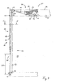
- the flap wall 14 is hinged in the region of the box bottom 16 and is there about a horizontal pivot axis 19 in a vertical pivot plane, for example, from its in FIG. 3 shown closing position 20 in an in FIG. 2 shown opening position 21 swung out, preferably by about 180 °.
- the lifting wall 13; 13.1; 13.2 can be based on the in FIG. 3 shown closed position rotatably to serve as a support and guide element 29, stationary arranged support and guide roller 30 via an in FIG. 1 shown intermediate position 45 in an in FIG. 2 respectively.
- FIG. 4 shown opening position 23, 24 are swung up.
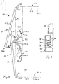
- link chain 26 is fixed with its one end to a receptacle. It is understood that instead of a link chain 26, a rope or the like can be used. As in particular from FIG. 5 it can be seen, the link chain 26 is in the closed state of the side wall 12 in a Runge recess 76 of the stanchion 17 and is covered by edging profiles 79 of the lifting wall 13 and not shown corresponding enclosure profiles of the flap wall 14 in the closed state and is therefore not from the outside in the closed position visible, noticeable.
- the link chain 26 extends with an inner chain portion 77 upwards and is arranged at a in the region of the lateral edge of the box roof 15 and about a parallel to the pivot axis 19 rotatable pulley 27, which is designed here as a sprocket. From there, the link chain 26 runs with its outer chain part 78 along the lifting wall 13, at the, in FIG. 3 shown closed position 22 lower end 37, the other end of the link chain 26 is also attached to a receptacle.
- the lifting wall 13 is supported on an inner side constantly on the support and guide roller 30 from whose axis of rotation 47 coincides in the embodiment with the axis of rotation 46 of the guide roller 27 and which is arranged laterally next to the guide roller 27 ( FIG. 6 ).
- the support and guide roller 30 is provided with at least one radially outwardly extending circumferential guide collar 81 for lateral guidance of the lifting wall 13; 13.1, 13.2 provided.
- two such support and guide rollers 30 are provided per side wall, which are arranged in a width of the lifting wall 13 corresponding distance from each other and each have a guide collar 81 at their ends laterally outwardly extending ends.
- the distance 28 of the point of attack for the traction means 25 on the flap wall 14 of the pivot axis 19 is selected such that when the pivoted in its open position 21 folding wall 14, the lifting wall 13; 13.1, 13.2 completely and without a supernatant in an open position 23, 24 is swung up, so they do not tower over the width of the box body 10 in the roof area 59 laterally and consequently not when loading and / or unloading of cargo, in particular by forklift , can not be damaged, so that the parts connected to the lifting wall are not damaged in this way.
- a handlebar 31 extending above the loading space 18; 31.1, 31.2 arranged.
- This handlebar 31; 31.1, 31.2 is about a first pivot axis 32 and handlebar axis 73.1, 73.2 of a at one of its ends 33 in the roof area 59 fixedly arranged first hinge 34; 34.1, 34.2 articulated freely pivotable and is also about a second pivot axis 35 of a arranged at its other end 36 and hinged to the lifting wall 13 in the region of its closed position in the upper end 38 38 second pivot joint 41 also pivotally.
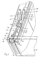
- the joints 34; 34.1, 34.2 and 41 are preferably each as a hinge with a parallel to each other arranged rotational axis designed, each perpendicular to a vertical pivot plane of the lifting wall 13; 13.1, 13.2 can be arranged.
- the first, lower hinge 34; 34.1, 34.2 is part of a in the roof area 59, preferably on a mounting rail 80, during the pivotal movement of the arm 31 stationary, preferably releasably secured Umlenkgephases 60, which is designed in the embodiment with two parallel, vertically upwardly extending legs 61.1 and 62.2 (see especially FIG. 6 ).
- the first pivot axis 32; 73.1, 73.2 of the fixedly arranged first articulation 34; 34.1, 34.2 and the second pivot axis 35 of the articulated with the lifting wall 13 second articulation 41 of the handlebar 31; 31.1, 31.2 are arranged at a distance 43 from each other, here about half of the height 44 of the lifting wall 13; 13.1, 13.2 corresponds.
- FIG. 3 shown closed position 22 to a in FIG. 2 or in FIG. 4 shown open position 23, 24 to pivot high, in which the lifting wall 13; 13.1, 13.2 completely over the roof 15 and without lateral projection on the vertical alignment of the box body 10 can be pivoted upwards.
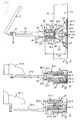
- variable adjustment of the distance 43 of the length of the handlebar 31; 31.1, 31.2 includes this in the shown Embodiment two telescopically guided into each other profile parts, namely a profile bar 49 and a profile tube 50 whose inner contour is designed to match the outer contour of the profile bar 49, so that the profile bar 49 in the longitudinal direction of the tube axis of the profile tube 50 in the profile tube 50 is displaceable.
- both the profile tube 50 and the profile bar guided therein 49 in the longitudinal direction of the handlebar 31 spaced in a row of holes arranged through holes, through which one or more locking pins 75 for fixing the profile bar 49 on the profile tube 50 in the desired distance length can be pushed.
- Their respective first end 54.1 engages at a first distance 52 from the first pivot axis 32; 73.1, 73.2 of the handlebar 31; 31.1, 31.2 on a fastening means connected thereto, here in the form of a fastening bolt, the or with the handlebar 31; 31.1, 31.2 about the first pivot axis 32; 73.1, 73.2 is pivotable when the handlebar 31; 31.1, 31.2 about the pivot axis 32; 73.1, 73.2 is pivoted.
- the respective second end 54.2 of the tension springs 53; 53.1 to 53.4 engages at a second distance 57 from the first pivot axis 32; 73.1, 73.2 of the handlebar 31; 31.1, 31.2 at a spring engagement point 58; 58.1 to 58.5, which is fixedly connected to the roof area 59.
- the second distance 57 in the embodiment shown is smaller than the first distance 52.
- the spring engagement points 58; 58.1 to 58.5 are here designed as hinges or axes of rotation, in the embodiment for a suspension 63; 63.1, 63.2 for the springs 53.1 to 53.4, whereby the travel of the springs is advantageously extended.
- the suspension 63; 63.1, 63.2 has in the region of its one end in the vertical pivoting plane of the handlebar 31; 31.1, 31.2 extending fastening bolt, which serves as a fastening means for the respective second ends 54.2 of the tension springs 53.1 to 53.4, as in particular from FIG. 7 seen.
- the suspension 63; 63.1, 63.2 is a parallel to the first pivot axis 32, 73.1, 73.2 of the handlebar 31; 31.1, 31.2 at a distance 61 arranged rotation axis 66 rotatably, which is rotatably mounted in the illustrated embodiment at the middle of here a total of 5 spring engagement points 58.1 to 58.5.
- the suspension 63; 63.1, 63.2 may also be omitted if appropriate, in which case the springs 53.1 to 53.4 can be optionally fixed directly to the spring engagement points 58.1 to 58.5.
- the spring engagement points 58.1 to 58.5 are preferably formed as a hinge or pivot point for the springs 53.1 to 53.4. It is further understood that, if necessary, only a single tension spring can be used instead of four tension springs.
- the suspension 63; 63.1, 63.2 designed with an elongated profile 64 having a first attachment point 65.1 for a first spring 53.1 and having a second attachment point 65.2 for a second spring 53.2, wherein the Attachment points are here formed at the transverse to the elongated profile 64 extending fastening bolts, and wherein the axis of rotation 66 of the suspension 63 between the first spring 53.1 and the second spring 53.2 is arranged.
- the suspension 63; 63.1, 63.2 is designed in the embodiment as an on either side of the axis of rotation 66 extending elongate profile 64, so with the axis of rotation 66 extending in opposite directions profile legs, so that a favorable support of the suspension 63 on both sides of the axis of rotation 66 and on both sides of the elongated Profile 64 arranged tension springs 53.1 and 53.2 is possible.
- the link arm 31 To the handlebar side attachment of the springs 53.1 to 53.4 is on the link arm 31; 31.1, 31.2 designed as a sliding part 67 fastening body 66 is provided, on which the springs 53.1 to 53.4 attack and which is intended to adjust different spring voltages can.
- the springs 53.1 to 53.4 engage approximately parallel to the first pivot axis 32; 73.1, 73.2 of the handlebar 31; 31.1, 31.2 in each case laterally outwardly extending fastening bolts to fastening points 65.1 to 65.4, wherein two springs are arranged on sides facing away from each other of the handlebar 31 ( FIGS. 8 and 9 ).
- the sliding part 67 is on the handlebar 31; 31.1, 31.2 arranged along the same slidably.
- the sliding part 67 has a transversely to the handlebar axis 32, 73.1, 73.2 extending leg 68, which in the embodiment with a along the handlebar 31; 31.1, 31.2 extending internal thread 69 is formed, in which a threaded male bolt 70 designed with a matching external thread 71 is screwed, whose protruding from the leg 68 on its other side end is supported on a transverse leg 72 of the handlebar 31 (see in particular FIG. 6 ).
- the distance of the sliding part 67 and thus the distance of the fixing bolts used for fastening relative to the first pivot axis 32; 73.1, 73.2 of the handlebar 31; 31.1, 31.2 are set differently, whereby different spring voltages can be adjusted.
- the box body 10 can preferably be provided at its opposite longitudinal end faces in each case with a two-winged side wall 12.1 and 12.2.
- the side walls 12.1 and 12.2 are preferably made of substantially equal parts, as the side wall 12 according to the FIGS. 1 to 3 and 5 to 7, with the exception of the handlebar constructions ( FIGS. 8 and 9 ).
- a first link 31.1 of a first side wall 12.1 can be pivotably mounted about a pivot axis 74.1 about a pivot axis 74.1 in the roof area 59 of the box structure 10, wherein a second link 31.2 of a second side wall 12.2 is also fixed in the roof area 59 of the box structure 10 arranged second link shaft 73.2 may be pivotally mounted about a rotational axis 74.2, wherein the second link 31.2 is arranged offset in the direction of the axis of rotation 74.1 of the first link 31.1 transversely to the first link 31.1.
- these handlebar constructions differ essentially by different attachment means, here fastening bolts, to which the second ends of the springs 53.1 to 53.4 are fastened, and also by the position and arrangement of the links 31.1, 31.2 relative to their Swivel axles 73.1 and 73.2, while the springs 53.1 to 53.4, the suspensions 63.1, 63.2 and the deflection housing 60 are designed with their vertically upstanding legs 62.1 and 62.2 each equal.
- the opening of the double-winged side wall 12, starting from the in FIG. 3 Shown closed position shown, in which therefore the lifting wall 13 in its closed position 22 and in which the flap wall 14 is in its closed position 20.
- the flap wall 14 is preferably pivoted manually in the direction of the arrow 82 about its pivot axis 19 down.
- flexible traction means 25 causes the lifting wall 13 first enters into an open position corresponding intermediate position 45, as shown FIG. 1 seen.
- the lifting wall 13 by the on her in the closed position 22, the upper end 38 is guided over the articulated arm 41 on the link 31, which is pivoted in the course of the pivoting of the lifting wall 13 about its also designated as a pivot axis 32 link axis.
- the lifting wall 13 is guided and supported by the support and guide roller, to which it preferably constantly rests under a sliding rotary motion.
- the lifting wall 13 is completely pivoted on the loading space 18 vertically upwardly bound box roof 15, to a position in which the lifting wall 13 no longer protrudes laterally beyond the vertical alignment of the box body 10, as in FIG. 2 shown.
- the tension springs 53.1 to 53.4 are provided as a force storage 51.
- the springs 53 are arranged and fixed so that they are in the in FIG. 3 shown closed position 22 of the lifting wall 13 a whose opening movement assisting torque (arrow 83) exert on the handlebar 31, while in the in FIG. 2 shown opening position 23 of the lifting wall 13 on the handlebar 31 in the direction of the arrow 84, that is opposite acting torque exert.
Abstract
Description
Die Erfindung betrifft einen Kastenaufbau, insbesondere für Nutzfahrzeuge, mit einem Kastenboden, einem Kastendach, einem Laderaum und wenigstens einer zweiflügeligen Seitenwand, die eine im Bereich des Kastenbodens angelenkte und vorzugsweise um etwa 180° um eine Anlenkachse aus ihrer Schließlage in eine Öffnungslage herausschwenkbaren Klappwand aufweist, und mit einer im Dachbereich in eine Öffnungsstellung hochschwenkbaren Hubwand, die mit der Klappwand mit wenigstens einem biegbaren Zugmittel, vorzugsweise einem Seil oder einer Kette, wirkverbunden ist, das um eine im Dachbereich angeordnete Umlenkrolle geschlungen ist und an der Klappwand im Abstand von der Anlenkachse angreift, so dass beim Herabklappen der Klappwand die Hubwand in eine Öffnungsstellung gelangt, und wobei im Dachbereich ein Stütz- und Führungselement angeordnet ist, an dem die Hubwand beim Verschwenken von ihrer Schließstellung in ihre Öffnungsstellung und umgekehrt unter gleichzeitiger Verschiebung relativ zu dem Stütz- und Führungselement anliegt, und mit einem sich oberhalb des Laderaums erstreckenden Lenker für die Hubwand.The invention relates to a box body, in particular for commercial vehicles, with a box bottom, a box roof, a cargo space and at least one two-leaf side wall, which has a hinged in the region of the box bottom and preferably by about 180 ° about a pivot axis from its closed position in an open position swing out flap wall , and with a liftable in the roof area in an open position lifting wall, which is operatively connected to the flap wall with at least one bendable traction means, preferably a rope or a chain, which is wrapped around a arranged in the roof area pulley and on the flap wall at a distance from the pivot axis attacks, so that when folding down the flap wall, the lifting wall enters an open position, and wherein in the roof area a support and guide element is arranged, on which the lifting wall when pivoting from its closed position to its open position and vice versa with simultaneous displacement re Lativ to the support and guide element is present, and with a above the load compartment extending handlebar for the lifting wall.
Ein derartiger Kastenaufbau ist aus der
Ähnliche Konstruktionen mit ähnlichen oder weiteren Nachteilen sind beispielsweise aus der
Aus der gattungsgemäßen
Es ist eine Aufgabe der Erfindung, die aus dem Stand der Technik bekannt gewordenen Kastenaufbauten zu verbessern.It is an object of the invention to improve the box structures known from the prior art.
Diese Aufgabe wird durch die Merkmale des Anspruchs 1 dadurch gelöst, dass Mittel zur variablen Einstellung des Abstandes zwischen dem ersten Gelenk des Lenkers und dem zweiten Gelenk des Lenkers vorgesehen sind.This object is solved by the features of
Dabei ist es zweckmäßig, wenn die genannten Mittel eine gestufte oder in bestimmten Rastabständen mögliche Einstellung des Abstandes erlauben oder wenn die genannten Mittel eine stufenlose Einstellung des Abstandes zwischen den beiden Gelenken ermöglicht. Dies ist beispielsweise durch teleskopierbar ineinander geführte Profilteile realisierbar. Auf diese Weise kann also die Länge des Lenkers auf unterschiedliche Hubwandhöhen eingestellt werden, so dass konstruktiv und unter Kostengesichtspunkten vorteilhaft nur ein einziger Lenker für jeweils unterschiedliche Hubwandhöhen verwendbar.It is expedient if the said means allow a stepped or in certain rest intervals possible adjustment of the distance or if said means allows a stepless adjustment of the distance between the two joints. This can be achieved, for example, by means of telescopically guided profile parts. In this way, therefore, the length of the arm can be adjusted to different Hubwandhöhen, so that constructively and in terms of cost advantageously only a single handlebar for different Hubwandhöhen used.
Vorteilhafterweise ist nur ein einziger Lenker vorgesehen.Advantageously, only a single link is provided.
Es ist ferner von Vorteil, wenn die erste Schwenkachse des ersten Gelenks und die zweite Schwenkachse des zweiten Gelenks des Lenkers in einem Abstand voneinander angeordnet sind, der etwa der Hälfte der Höhe der Hubwand entspricht. Dies bedeutet eine günstige Minimallänge für den starren Lenker, um ausgehend von der Schließstellung der Hubwand, ein vollständiges nach oben Schwenken derselben ohne seitlichen Überstand über das Dach erreichen zu können.It is also advantageous if the first pivot axis of the first joint and the second pivot axis of the second joint of the link are arranged at a distance from each other which corresponds to about half the height of the lifting wall. This means a favorable minimum length for the rigid arm, to reach from the closed position of the lifting wall, a complete upward pivoting the same without lateral projection over the roof.
Es ist ferner vorteilhaft, wenn die Hubwand und/oder der Lenker zumindest in einer Zwischenstellung zwischen der Öffnungsstellung und der Schließstellung der Hubwand über eine obere Dachkante des Kastendaches nach oben hinaus ragt.It is also advantageous if the lifting wall and / or the handlebar protrudes at least in an intermediate position between the open position and the closed position of the lifting wall over an upper roof edge of the box roof upwards.
Es ist ferner vorteilhaft, wenn nur eine einzige Umlenkrolle für das Zugmittel vorgesehen ist.It is also advantageous if only a single deflection roller is provided for the traction means.
Schließlich kann vorgesehen sein, dass das Stütz- und Führungselement als Stütz- und Führungsrolle ausgebildet ist, die vorzugsweise koaxial zu der Umlenkrolle und ortsfest im Bereich einer seitlichen Kante des Kastendaches angeordnet ist.Finally, it can be provided that the support and guide element is designed as a support and guide roller, which is preferably arranged coaxially to the deflection roller and fixed in the region of a lateral edge of the box roof.
Günstige Voraussetzungen für ein vollständiges nach oben Schwenken der Hubwand über das Kastendach ohne seitlichen Überstand können auch dann erreicht werden, wenn das Zugmittel im Bereich des unteren Endes der Hubwand an dieser angreift.Favorable conditions for a complete upward pivoting of the lifting wall on the box roof without lateral projection can also be achieved when the traction means engages in the region of the lower end of the lifting wall at this.
Gemäß einer besonders vorteilhaften Ausführungsvariante der Erfindung kann vorgesehen sein, dass die Hubwand beim Verschwenken von ihrer Schließstellung in ihre Öffnungsstellung und umgekehrt ständig an dem Stütz- und Führungselement anliegt. Dadurch lassen sich besonders günstige Führungsverhältnisse für die Hubwand bei einer besonders einfachen und kostengünstigen Konstruktion erreichen.According to a particularly advantageous embodiment of the invention can be provided that the lifting wall during Pivoting from its closed position into its open position and vice versa constantly applied to the support and guide element. This makes it possible to achieve particularly favorable guiding conditions for the lifting wall in a particularly simple and inexpensive construction.
Es ist ferner von Vorteil, wenn wenigstens ein im Dachbereich vorgesehener Kraftspeicher vorgesehen ist, der im Abstand von der ersten Schwenkachse an dem Lenker angreift, so dass der Schließvorgang und/oder der Öffnungsvorgang der Hubwand unterstützt ist. Dabei ist es besonders vorteilhaft, wenn es sich bei dem Kraftspeicher um eine Zugfeder handelt, deren erstes Ende in einem ersten Abstand von der ersten Schwenkachse des Lenkers an einem mit diesem verbundenen Befestigungsmittel angreift, das zusammen mit dem Lenker um die erste Schwenkachse schwenkbar ist und deren zweites Ende in einem gegenüber dem ersten Abstand kleineren zweiten Abstand von der ersten Schwenkachse des Lenkers an einer Federangriffsstelle angreift, die ortsfest mit dem Dachbereich verbunden ist. Dadurch lässt sich eine besonders kompakte und kostengünstige Anordnung schaffen, ohne dass irgendwelche Teile in den von dem Kastenboden, dem Kastendach und der zweiflügeligen Seitenwand begrenzten Laderaum hineinstehen würden.It is also advantageous if at least one provided in the roof area power storage is provided which acts at a distance from the first pivot axis of the handlebar, so that the closing operation and / or the opening operation of the lifting wall is supported. It is particularly advantageous if the energy accumulator is a tension spring whose first end engages at a first distance from the first pivot axis of the link on a fastener connected thereto, which is pivotable together with the link around the first pivot axis and whose second end engages in a second distance, which is smaller than the first distance, from the first pivot axis of the link to a spring engagement point which is fixedly connected to the roof area. As a result, a particularly compact and inexpensive arrangement can be created without any parts would protrude into the limited space from the box bottom, the box roof and the double-wing side wall cargo space.
Dabei ist es ferner vorteilhaft, wenn die Federangriffsstelle an einem im Dachbereich ortsfest angeordneten Umlenkgehäuse in einem vertikalen Abstand oberhalb der vorzugsweise an dem Umlenkgehäuse gelagerten ersten Schwenkachse angeordnet ist. Es ist demgemäß möglich, eine oder mehrere Zugfedern an der bzw. den Federangriffsstellen zu befestigen. Gemäß einer besonders vorteilhaften Ausführungsvariante kann vorgesehen sein, dass die oder jede Federangriffsstelle mit einem Gelenk für eine um eine Drehachse drehbare Aufhängung für die Feder ausgebildet ist, an der das zweite Ende der Zugfeder befestigt ist. Dadurch ist eine günstige Verlängerung des Federweges möglich bzw. sind längere Zugfedern, die ggf. auch mit eine geringere Federsteigung aufweisen können, einbaubar.It is also advantageous if the spring engagement point is arranged at a stationary in the roof area deflecting housing in a vertical distance above the first pivot axis preferably mounted on the Umlenkgehäuse. It is accordingly possible to fasten one or more tension springs to the spring engagement point (s). According to a particularly advantageous embodiment, it can be provided that the or each spring engagement point is formed with a hinge for a pivotable about an axis of rotation suspension for the spring to which the second end of the tension spring is attached. As a result, a favorable extension of the spring travel is possible or longer extension springs, which may possibly also have a lower spring pitch, can be installed.
Zum Ausgleich von unterschiedlichen Gewichtsverhältnissen der Hubwand und der Klappwand können mehrere Federangriffsstellen vorgesehen sein, an denen die Zugfeder wahlweise festlegbar ist, wobei wenigstens eine Federangriffsstelle quer zur ersten Schwenkachse in Horizontalrichtung gegenüber einer benachbarten Federangriffsstelle versetzt angeordnet sein kann. Auf diese Weise können beim Öffnen und Schließen etwa die gleichen Betätigungskräfte eingestellt werden.To compensate for different weight ratios of the lifting wall and the flap wall a plurality of spring engagement points may be provided, on which the tension spring is selectively fixed, wherein at least one spring engagement point can be arranged offset transversely to the first pivot axis in the horizontal direction relative to an adjacent spring attack point. In this way, about the same actuating forces can be adjusted when opening and closing.
Gemäß einer vorteilhaften Weiterbildung der Erfindung kann die Aufhängung mit einem langgestreckten Profil gestaltet sein, das eine erste Befestigungsstelle für eine erste Feder aufweist und das eine zweite Befestigungsstelle für eine zweite Feder aufweist, wobei die Drehachse der Aufhängung zwischen der ersten Feder und der zweiten Feder angeordnet ist. Dies ermöglicht günstige Federkraftverhältnisse sowohl beim Öffnen als auch beim Schließen der Hubwand im Sinne einer günstigen Unterstützung der Öffnungsbewegung und der Schließbewegung.According to an advantageous embodiment of the invention, the suspension can be designed with an elongated profile having a first attachment point for a first spring and having a second attachment point for a second spring, wherein the axis of rotation of the suspension between the first spring and the second spring arranged is. This allows favorable spring force conditions both when opening and when closing the lifting wall in terms of a favorable support the opening movement and the closing movement.
Es ist ferner vorteilhaft, wenn die Aufhängung als ein sich beiderseits der Drehachse erstreckendes Profil gestaltet ist, was eine vorteilhafte Abstützung der Aufhängung über beiderseits der Drehachse angeordnete Federn ermöglicht.It is also advantageous if the suspension is designed as a profile extending on either side of the axis of rotation, which enables advantageous support of the suspension via springs disposed on either side of the axis of rotation.
Ferner kann eine erste Befestigungsstelle für die erste Feder an einer quer zur Drehachse der Aufhängung und quer zu einem langgestreckten Profil der Aufhängung angeordneten Befestigungsposition vorgesehen sein und eine zweite Befestigungsstelle für eine zweite Feder an einer in etwa entgegengesetzter Richtung quer zur Drehachse der Aufhängung und quer zu dem Profil angeordneten Befestigungsposition, und ferner kann an dem Lenkerarm eine dritte Befestigungsstelle für die erste Feder an einer quer zu diesem und quer zu seiner Lenkerachse angeordneten Befestigungsposition vorgesehen sein, und schließlich kann eine vierte Befestigungsstelle für die zweite Feder an einer in etwa entgegengesetzten Richtung quer zu dem Lenkerarm und quer zu seiner Lenkerachse angeordneten Befestigungsposition vorgesehen sein.Further, a first attachment point for the first spring may be provided on a mounting position transverse to the axis of rotation of the suspension and transverse to an elongate profile of the suspension, and a second attachment point for a second spring at an approximately opposite direction transverse to the axis of rotation of the suspension and transverse to the profile arranged mounting position, and further may be provided on the link arm, a third attachment point for the first spring at a transverse to this and transverse to its handlebar axis mounting position, and finally, a fourth attachment point for the second spring in an approximately opposite direction across be provided to the link arm and arranged transversely to its handlebar axis mounting position.
Es ist schließlich vorteilhaft, wenn an dem Lenkerarm ein Befestigungskörper befestigt ist, an dem wenigstens eine der Federn angreift und der dazu bestimmt ist, unterschiedliche Federspannungen einstellen zu können. Mit Hilfe dieses Befestigungskörpers kann dann die Feder beliebig gespannt werden, so dass auch insoweit unterschiedliche Gewichtsverhältnisse von Hubwand und Klappwand ausgeglichen werden können. Dabei ist es zweckmäßig, wenn der Befestigungskörper eine stufenlose Einstellung der Federspannung ermöglicht.Finally, it is advantageous if a fastening body is attached to the link arm, on which at least one of the springs engages and which is intended to be able to set different spring voltages. With the help of this fixing body, the spring can then be stretched as desired, so that in this respect different weight ratios of lifting wall and folding wall can be compensated. It is expedient if the fastening body allows a continuous adjustment of the spring tension.
In konkreterer Ausgestaltung kann vorgesehen sein, dass der Befestigungskörper als ein sich an dem Lenkerarm abstützender und längs desselben verschiebbarer Schiebeteil gestaltet ist, an dem ein Schenkel mit einem sich längs des Lenkerarms erstreckenden Innengewindes einer Durchgangsbohrung befestigt ist, in dem ein Gewindebolzen mit Außengewinde eingeschraubt ist, dessen freies und aus dem Schenkel herausragendes Ende sich an einem Querschenkel des Lenkerarms abstützt, so dass durch Drehen des Gewindebolzens um seine Längsachse eine Verschiebung des Schiebeteils längs des Lenkers und folglich eine Spannung oder Entspannung der wenigstens einen Feder erreichbar ist.In a more concrete embodiment, it may be provided that the fastening body is designed as a sliding on the handlebar and along the same displaceable sliding part, on which a leg is fixed with an extending along the handlebar internal thread of a through hole, in which a threaded bolt with external thread is screwed, the free and protruding from the leg end is supported on a transverse leg of the link arm, so that by turning the threaded bolt about its longitudinal axis displacement of the sliding member along the handlebar and consequently a tension or relaxation of at least one spring can be reached.
Von besonderem Vorteil ist es, wenn der Kastenaufbau an seinen beiden seitlichen Stirnseiten jeweils eine zweiflügelige Seitenwand nach einem der Ansprüche 1 bis 19 aufweist, wobei ein erster Lenker einer ersten Seitenwand um eine im Dachbereich des Kastenaufbaus ortsfest angeordnete erste Lenkerachse schwenkbar gelagert ist, und wobei ein zweiter Lenker einer zweiten Seitenwand um eine im Dachbereich des Kastenaufbaus ortsfest angeordnete zweite Lenkachse schwenkbar gelagert ist, wobei der zweite Lenker in Richtung der Drehachse des ersten Lenkers versetzt angeordnet ist, so dass sich bei vollständig über das Kastendach hochgeschwenkten und sich im Bereich ihrer in den Schließlagen oberen Enden überlappenden Hubwänden die beiden Lenker überkreuzen. Auf diese Weise lässt sich also ein Kastenaufbau mit zwei gegenüberliegend angeordneten Seitenwänden mit höheren Hubwänden schaffen, beispielsweise mit einer Höhe von mehr als 1250 mm, insbesondere von mehr als 1600 mm. Ferner kann durch die vorgenannten Maßnahmen in einfacher Weise zunächst die eine Hubwand nahezu flach auf das Dach legen und zweckmäßiger Weise anschließend kann die zweite Hubwand schräg darüber gelegt werden, wobei sich dann die Hubwände an ihren in Schließstellung oberen Enden teilweise überlappen. Dies ist gegenüber aus dem Stande der Technik bekannt gewordenen Ausführungen mit klappbaren Teil-Hubwänden oder bei denen die Hubwände um 45° nach oben gestellt werden müssen, deutlich einfacher und/oder wird nicht soviel Platz benötigt.It is particularly advantageous if the box structure at its two lateral end faces each having a two-leaf side wall according to one of
Weitere Vorteile, Merkmale und Gesichtspunkte der Erfindung sind dem nachfolgenden Beschreibungsteil entnehmbar, in dem ein vorteilhaftes Ausführungsbeispiel der Erfindung anhand der Figuren beschrieben wird.Further advantages, features and aspects of the invention can be taken from the following description part, in which an advantageous embodiment of the invention is described with reference to FIGS.
Es zeigen:
- Fig. 1:
- einen Teilquerschnitt eines Kastenaufbaus mit seitlich teilweise geöffneter Ladewand, wobei aus Darstellungsgründen die Zugfedern weggelassen wurden;
- Fig. 2:
- einen Teilquerschnitt eines Kastenaufbaus bei vollständig geöffneter Ladewand;
- Fig. 3:
- einen Teilquerschnitt eines Kastenaufbaus bei vollständig geschlossener Ladewand;
- Fig. 4:
- einen Teilquerschnitt im Dachbereich über die gesamte Breite eines Kastenaufbaus mit beiderseits desselben angeordneten, jeweils vollständig geöffneten Hubwänden, wobei aus Darstellungsgründen die Zugfedern weggelassen wurden;
- Fig. 5:
- einen Teilquerschnitt im Bereich einer vertikalen Runge eines Kastenaufbaus bei geschlossener Hubwand;
- Fig. 6:
- eine dreidimensionale Teildarstellung eines Kastenaufbaus im Dachbereich bei geschlossener Hubwand, wobei aus Darstellungsgründen die Zugfedern weggelassen wurden;
- Fig. 7:
- eine Seitenansicht im Bereich eines Lenkers für eine Hubwand;
- Fig. 8:
- eine gegenüber der Darstellung von
Fig. 7 um 90° nach links gedrehte Ansicht im Bereich eines ersten Lenkers für eine erste Hubwand; - Fig. 9:
- eine der
Fig. 8 entsprechende Ansicht im Bereich eines zweiten Lenkers für eine zweite Hubwand.
- Fig. 1:
- a partial cross-section of a box structure with laterally partially open loading wall, for reasons of illustration, the tension springs have been omitted;
- Fig. 2:
- a partial cross-section of a box body with fully open loading wall;
- 3:
- a partial cross section of a box body with fully closed loading wall;
- 4:
- a partial cross section in the roof area over the entire width of a box structure arranged on both sides of the same, in each case completely open Hubwänden, for drawing reasons, the tension springs have been omitted;
- Fig. 5:
- a partial cross section in the region of a vertical Runge of a box structure with closed lift wall;
- Fig. 6:
- a three-dimensional partial view of a box structure in the roof area with closed Lifting wall, wherein for reasons of clarity, the tension springs have been omitted;
- Fig. 7:
- a side view in the region of a handlebar for a lifting wall;
- Fig. 8:
- one opposite the representation of
Fig. 7 rotated 90 ° to the left in the view of a first link for a first lifting wall; - Fig. 9:
- one of the
Fig. 8 corresponding view in the region of a second link for a second lifting wall.
Der Kastenaufbau 10 eines Nutzfahrzeuges ist vorzugsweise mit zwei seitlichen Ladewänden 11; 11.1, 11.2 ausgestattet, die jeweils als eine zweiflügelige Seitenwand 12; 12.1, 12.2 gestaltet sind, welche wiederum jeweils aus einer Hubwand 13; 13.1, 13.2 und einer Klappwand 14 gebildet ist. Der Kastenaufbau 10 besteht im Wesentlichen aus einem Kastendach 15, einem Kastenboden 16 und den zweiflügeligen Seitenwänden 12; 12.1, 12.2 und wenigstens an den Eckpunkten des Kastenaufbaus 10 aus vertikalen, das Kastendach 15 mit dem Kastenboden 16 verbindenden vertikalen Rungen 17. Die vorgenannten Teile begrenzen einen Laderaum 18.The
Die Klappwand 14 ist im Bereich des Kastenbodens 16 angelenkt und ist dort um eine horizontale Anlenkachse 19 in einer vertikalen Schwenkebene beispielsweise aus ihrer in
In einem Abstand 28 von der Anlenkachse 19 der unteren Klappwand 14 ist eine als biegbares Zugmittel 25 fungierende Gliederkette 26 mit ihrem einem Ende an einer Aufnahme befestigt. Es versteht sich, dass anstelle einer Gliederkette 26 auch ein Seil oder dergleichen verwendet werden kann. Wie insbesondere aus
Insbesondere der Abstand 28 des Angriffpunktes für das Zugmittel 25 an der Klappwand 14 von deren Anlenkachse 19 ist derart gewählt, dass bei der in ihre Öffnungslage 21 verschwenkten Klappwand 14 die Hubwand 13; 13.1, 13,2 vollständig und ohne seitlichen Überstand in eine Öffnungsstellung 23, 24 hochgeschwenkt ist, in der sie also die Breite des Kastenaufbaus 10 im Dachbereich 59 seitlich nicht überragt und folglich auch nicht beim Beladen und/oder Entladen von Ladegut, insbesondere durch Stapler, nicht beschädigt werden kann, so dass auch die mit der Hubwand verbundenen Teile auf diese Weise nicht beschädigt werden.In particular, the
Als weiteres Führungselement für die Hubwand 13; 13.1, 13.2 ist ein sich oberhalb des Laderaums 18 erstreckender Lenker 31; 31.1, 31,2 angeordnet. Dieser Lenker 31; 31.1, 31.2 ist um eine erste Schwenkachse 32 bzw. Lenkerachse 73.1, 73.2 eines an einem seiner Enden 33 im Dachbereich 59 ortsfest angeordneten ersten Gelenks 34; 34.1, 34.2 frei schwenkbar angelenkt und ist um eine zweite Schwenkachse 35 eines an seinem anderen Ende 36 angeordneten und mit der Hubwand 13 im Bereich ihres in der Schließstellung 22 oberen Endes 38 verbundenen zweiten Gelenks 41 ebenfalls schwenkbar angelenkt. Die Gelenke 34; 34.1, 34.2 und 41 sind vorzugsweise jeweils als ein Drehgelenk mit einer parallel zueinander angeordneten Drehachse gestaltet, die jeweils senkrecht zu einer vertikalen Schwenkebene der Hubwand 13; 13.1, 13.2 angeordnet sein können. Das erste, untere Gelenk 34; 34.1, 34.2 ist Teil eines im Dachbereich 59, vorzugsweise an einer Befestigungsschiene 80, während der Schwenkbewegung des Lenkers 31 ortsfest, vorzugsweise lösbar befestigten Umlenkgehäuses 60, das im Ausführungsbeispiel mit zwei parallelen, sich vertikal nach oben erstreckenden Schenkeln 61.1 und 62.2 gestaltet ist (siehe insbesondere
Zur variablen Einstellung des Abstandes 43 der Länge des Lenkers 31; 31.1, 31.2 umfasst dieser im gezeigten Ausführungsbeispiel zwei teleskopierbar ineinander geführte Profilteile, und zwar eine Profilstange 49 und ein Profilrohr 50, deren Innenkontur auf die Außenkontur der Profilstange 49 abgestimmt gestaltet ist, so dass die Profilstange 49 in Längsrichtung der Rohrachse des Profilrohrs 50 in dem Profilrohr 50 verschiebbar ist. Im Ausführungsbeispiel weisen sowohl das Profilrohr 50 als auch die darin geführte Profilstange 49 in Längsrichtung des Lenkers 31 beabstandete in einer Lochreihe angeordnete Durchgangslöcher auf, durch die ein oder mehrere Steckbolzen 75 zur Fixierung der Profilstange 49 an dem Profilrohr 50 in der gewünschten Abstandslänge hindurchsteckbar sind.For variable adjustment of the
Zur Unterstützung des Schließvorganges und des Öffnungsvorganges der Hubwand 13 sind im Ausführungsbeispiel mehrere, als Kraftspeicher 51 dienende Zugfedern 53; 53.1 bis 53.4 vorgesehen. Deren jeweiliges erstes Ende 54.1 greift in einem ersten Abstand 52 von der ersten Schwenkachse 32; 73.1, 73.2 des Lenkers 31; 31.1, 31.2 an einem mit diesem verbundenen Befestigungsmittel, hier in Form eines Befestigungsbolzens an, das bzw. der mit dem Lenker 31; 31.1, 31.2 um dessen erste Schwenkachse 32; 73.1, 73.2 mitschwenkbar ist, wenn der Lenker 31; 31.1, 31.2 um die Schwenkachse 32; 73.1, 73.2 verschwenkt wird. Das jeweilige zweite Ende 54.2 der Zugfedern 53; 53.1 bis 53.4 greift in einem zweiten Abstand 57 von der ersten Schwenkachse 32; 73.1, 73.2 des Lenkers 31; 31.1, 31.2 an einer Federangriffsstelle 58; 58.1 bis 58.5 an, die ortsfest mit dem Dachbereich 59 verbunden ist. Dabei ist der zweite Abstand 57 im gezeigten Ausführungsbeispiel kleiner als der erste Abstand 52. Die Federangriffsstellen 58; 58.1 bis 58.5 sind hier als Drehgelenke bzw. Drehachsen gestaltet, und zwar im Ausführungsbeispiel für eine Aufhängung 63; 63.1, 63.2 für die Federn 53.1 bis 53.4, wodurch der Federweg der Federn vorteilhaft verlängerbar ist. Die Aufhängung 63; 63.1, 63.2 weist im Bereich ihres einen Endes einen sich in der vertikalen Schwenkebene des Lenkers 31; 31.1, 31.2 erstreckenden Befestigungsbolzen auf, der als Befestigungsmittel für die jeweiligen zweiten Enden 54.2 der Zugfedern 53.1 bis 53.4 dient, wie insbesondere aus
Wie insbesondere aus
Zur lenkerseitigen Befestigung der Federn 53.1 bis 53.4 ist an dem Lenkerarm 31; 31.1, 31.2 ein als Schiebeteil 67 gestalteter Befestigungskörper 66 vorgesehen, an dem die Federn 53.1 bis 53.4 angreifen und der dazu bestimmt ist, unterschiedliche Federspannungen einstellen zu können. Im Ausführungsbeispiel greifen die Federn 53.1 bis 53.4 an sich etwa parallel zur ersten Schwenkachse 32; 73.1, 73.2 des Lenkers 31; 31.1, 31.2 jeweils seitlich nach außen erstreckenden Befestigungsbolzen an Befestigungsstellen 65.1 bis 65.4 an, wobei jeweils zwei Federn auf voneinander wegweisenden Seiten des Lenkers 31 angeordnet sind (
Der Schiebeteil 67 ist auf dem Lenker 31; 31.1, 31.2 längs desselben verschiebbar angeordnet. Der Schiebeteil 67 weist einen sich quer zur Lenkerachse 32, 73.1, 73.2 erstreckenden Schenkel 68 auf, der im Ausführungsbeispiel mit einem sich längs des Lenkers 31; 31.1, 31.2 erstreckenden Innengewinde 69 ausgebildet ist, in das ein mit passendem Außengewinde 71 gestalteter Gewindebolzen 70 eingeschraubt ist, dessen aus dem Schenkel 68 auf seiner anderen Seite herausragendes Ende sich an einem Querschenkel 72 des Lenkers 31 abstützt (siehe insbesondere
Aus
Nachfolgend wird das Öffnen der zweiflügeligen Seitenwand 12 ausgehend von der in
Claims (19)
- Box body (10), particularly for utility vehicles, with a box floor (16), a box roof (15), a loading space (18) and at least one double-panelled side wall (12; 12.1, 12.2), which comprises a folding wall (14) articulated in the region of the box floor (16) and pivotable out about a pivot axis (19) from its closed position (20) to an open position (21), and with a raisable wall (13; 13.1, 13.2), which is pivotable up in the roof region (59) into an open setting (23, 24) and which is connected with the folding wall (14) by at least one flexible traction means (25), which is looped around a deflecting roller (27) arranged in the roof region (59) and which engages the folding wall (14) at a spacing (28) from the pivot axis (19) so that when the folding wall (14) is folded down the raisable wall (13; 13.1, 13.2) goes into an open setting (23), and wherein arranged in the roof region (59) is a supporting and guiding element (29) against which the raisable wall (13; 13.1, 13.2) bears on pivotation from Its closed setting (22) into its open setting (23) and conversely with simultaneous displacement relative to the supporting and guide element (29), and with a guide (31; 31.1, 31.2), which extends above the loading space, for the raisable wall (13; 13.1, 13.2), wherein the guide (31; 31.1, 31.2) is articulated to be freely pivotable about a first pivot axis (32; 73.1, 73.2) of a first joint (34; 34.1, 34.2), which is arranged in stationary position at one of its ends (33) in the roof region (59), and articulated to be pivotable about a second pivot axis (35) of a second joint (41), which is arranged at its other end (36) and connected with the raisable wall (13; 13.1, 13.2) in the region of its end (38) which is upper in the closed setting (22), characterized in that means (48) for variable setting of the spacing (43) between the first joint (34; 34.1, 34.2) of the guide (31; 31.1, 31.2) and the second joint (41) of the guide (31; 31.1, 31.2) are provided.
- Box body according to claim 1, characterised in that a single guide (31; 31.1, 31.2) Is provided.
- Box body according to claim 1 or 2, characterised in that the first pivot axis (32; 73.1, 73.2) of the first joint (34; 34.1. 34.2) and the second pivot axis (35) of the second joint (41) of the guide (31; 31.1, 31.2) are arranged at a mutual spacing (52) corresponding with approximately halt the height (44) of the raisable wall (13; 13.1, 13.2).
- Box body according to any one of claims 1 to 3, characterised in that the raisable wall (13; 13.2, 13.2) and/or the guide (31; 31.1, 31.2) at least in an intermediate setting (45) between the open setting (23) and the closed setting (22) of the raisable wall (13; 13.1, 13.2) projects or project upwardly beyond an upper roof edge (42) of the box roof (15).
- Box body according to any one of claims 1 to 4, characterised in that a single deflecting roller (27) for the traction means (25) is provided.
- Box body according to claim 5, characterised in that the supporting and guiding element (29) is constructed as a supporting and guiding roller (30) which is arranged coaxially with the deflecting roller (27) and in stationary position in the region of a side edge of the box roof (15).
- Box body according to any one of claims 1 to 6, characterised in that the traction means (25) engages the raisable wall (13; 13.1, 13.2) in the region or the lower end (37) thereof.
- Box body according to any one of claims 1 to 7, characterised in that the raisable wall (13; 13.1, 13.2) on pivotation from its closed setting (22) into its open setting (23) and conversely constantly bears against the supporting and guiding element (29).
- Box body according to any one of claims 1 to 8, characterised in that at least one force store (51), which is arranged in the roof region (69) and engages the guide (31; 31.1, 31.2) at a spacing (52) from the first pivot axis (32; 73.1, 73.2), is provided so that the closing process and/or the opening process of the raisable wall (13' 13.1, 13.2) is assisted.
- Box body according to claim 9, characterised in that the force store (51) is a tension spring (53; 53.1 to 53.4), the first end (54.1) of which engages, at a spacing (52) from the first pivot axis (32; 73.1, 73.2) of the guide (31; 31.1, 31.2), a fastening means (86; 87.1, 87.2), which is connected therewith and which is pivotable with the guide (31; 31.1, 31.2) about the first pivot axis (32), and the second end (54.2) of which engages, at a second spacing (57) - which is smaller by comparison with the first spacing (52) - from the first pivot axis (32; 73.1, 73.2) of the guide (31; 31.1, 31.2), a spring engagement point (58; 58.1 to 58.5) connected in fixed position with the roof region (59).
- Box body according to claim 10, characterised in that the spring engagement point (58; 58.1 to 58.5) is arranged at a deflecting housing (60), which is arranged in fixed position in the roof region (59), at a vertical spacing (61) above the first pivot axis (32; 73.1, 73.2) mounted at the deflecting housing (60).
- Box body according to claim 10 or 11, characterised in that the spring engagement point (58; 58.1 to 58.5) is formed with a joint for a suspension means (63; 63.1, 63.2), which is rotatable about an axis (66) of rotation, for the spring (53; 53.1, to 53.4), to which suspension means of the second end (54.2) of the tension spring (53; 53.1 to 53.4) is fastened.
- Box body according to claim 11 or 12, characterised in that in order to provide compensation for different weight conditions of the raisable wall (13; 13.1, 13.2) and the folding wall (14) several spring engagement points (58; 58.1 to 58.5) are provided at which the tension spring (53; 53.1 to 53.4) Is selectably fixable, wherein at least one spring engagement point (58.1 to 58.5) is arranged transversely to the pivot axis (32) in horizontal direction opposite an adjacent spring engagement point.
- Box body according to claim 12 or 13, characterised in that the suspension means (63; 63.1, 63.2) is formed with an elongate profile (64) which has a first fastening point (65.1) for a first spring (53.1) and a second fastening point (65.2) for a second spring (53.2), wherein the axis (66) of rotation of the suspension means (63; 63.1, 63.2) is arranged between the first spring (53.1) and the second spring (53.2).
- Box body according to any one of claims 12 to 14, characterised in that the suspension means (63; 63.1, 63.2) is formed as a profile (64) extending on both sides of the axis (66) of rotation.
- Box body according to any one of claims 1 to 15, characterised in that a fastening body (85), at which the spring (53; 53.1 to 53.4) engages and which is intended for the purpose of being able to adjust different spring tensions, is fastened to the guide (31; 31.1, 31.2).
- Box body according to claim 16, characterised in that the fastening body (85) is intended for the purpose of enabling a stepless setting of the spring tension.
- Box body according to claim 16 or 17, characterised in that the fastening body (85) is formed as a slide part (67), which is supported at the guide (31; 31.1, 31.2) and displaceable therealong and to which a limb (68) with an internal thread (69) extending along the guide (31; 31.1, 31.2) is fastened, into which internal thread a threaded pin (70) with an external thread (71) is screwed, the end of the pin being supported at a transverse limb (72) of the guide (31; 31.1, 31.2).
- Box body according to any one of claims 1 to 18, characterised in that it has at each of its two lateral end faces a respective double-panelled side wall (12. 1, 12.2), wherein a first guide (31.1) of a first side wall (12.1) is mounted to be pivotable about a first guide axis (73.1) arranged in fixed position in the roof region (59) of the box body (10) and wherein a second guide (31.2) of a second side wall (12.2) is mounted to be pivotable about a second guide axis (73.2) arranged in stationary position in the roof region (59) of the box body (10), wherein the second guide (31.2) is arranged to be offset in the direction of the axis (74.1) of rotation of the first guide transversely to the first guide (31.1) so that the two guides (31.1, 31.2) intersect when raisable walls (13.1, 13.2) are pivoted up beyond the box roof (15) and overlap in the region of their ends (38.1, 38.2) upper in the closed settings thereof.
Priority Applications (2)
| Application Number | Priority Date | Filing Date | Title |
|---|---|---|---|
| DE202004021073U DE202004021073U1 (en) | 2003-09-19 | 2004-08-07 | Box body especially for commercial vehicles has link for lifting wall freely pivotable around first pivot of first joint fixed on one end in roof region, and around second pivot of second joint installed on other end |
| PL04018787T PL1516763T3 (en) | 2003-09-19 | 2004-08-07 | Body structure |
Applications Claiming Priority (2)
| Application Number | Priority Date | Filing Date | Title |
|---|---|---|---|
| DE10343915 | 2003-09-19 | ||
| DE10343915A DE10343915B4 (en) | 2003-09-19 | 2003-09-19 | box body |
Publications (3)
| Publication Number | Publication Date |
|---|---|
| EP1516763A2 EP1516763A2 (en) | 2005-03-23 |
| EP1516763A3 EP1516763A3 (en) | 2007-01-17 |
| EP1516763B1 true EP1516763B1 (en) | 2009-11-04 |
Family
ID=34177894
Family Applications (1)
| Application Number | Title | Priority Date | Filing Date |
|---|---|---|---|
| EP04018787A Not-in-force EP1516763B1 (en) | 2003-09-19 | 2004-08-07 | Body structure |
Country Status (4)
| Country | Link |
|---|---|
| EP (1) | EP1516763B1 (en) |
| AT (1) | ATE447502T1 (en) |
| DE (3) | DE10343915B4 (en) |
| PL (1) | PL1516763T3 (en) |
Families Citing this family (2)
| Publication number | Priority date | Publication date | Assignee | Title |
|---|---|---|---|---|
| DE102006053523B3 (en) * | 2006-11-07 | 2008-01-31 | Orten Karlsdorf-Neuthard Gmbh & Co. Kg | Device for transfer of single part wall of box body of commercial vehicle, from closed position to open position and from open position to closed position, has loading space with narrow bottom and has loading space with narrow roof |
| AT508096B1 (en) * | 2009-04-09 | 2011-01-15 | Strasser Johann Sen | DEVICE FOR TRANSFERRING A SIDE WALL OF A TRANSPORT CONTAINER |
Family Cites Families (12)
| Publication number | Priority date | Publication date | Assignee | Title |
|---|---|---|---|---|
| DE7707180U1 (en) | 1977-03-09 | 1977-08-11 | Heinz Boese Kg, 5779 Reiste | Structure for a truck or trailer with tail lifts |
| DE2813593C2 (en) | 1978-03-30 | 1982-02-11 | Franz 5778 Meschede Ewers | Side wall for box bodies of trucks |
| DE2931111C2 (en) | 1979-07-31 | 1984-04-05 | Diamoil S.A., 1207 Genève | Vehicle body with side walls divided in the horizontal direction |
| DE3121690A1 (en) * | 1981-06-01 | 1982-12-16 | F.X. Kögel GmbH & Co Fahrzeugwerke, 7900 Ulm | Split lift gate |
| DE3219505A1 (en) | 1982-05-25 | 1983-12-01 | F.X. Kögel GmbH & Co Fahrzeugwerke, 7900 Ulm | Tailgate for covered motor vehicle superstructures |
| EP0116722B1 (en) | 1983-01-26 | 1987-04-15 | TREFA - Jürgen Nichts Karosserie- und Fahrzeugtechnik GmbH & Co KG | Device for the simultaneous opening or closing of an under and an upper part of a side-board |
| DE3525628A1 (en) | 1985-07-18 | 1987-01-22 | Gross Aluminium Gmbh | Folding side- or tailboard, in particular for vehicle superstructures |
| DE4033691C2 (en) | 1990-10-23 | 1999-03-04 | Georg Maierbacher | Sidewall arrangement for covered box bodies |
| DE4427518C1 (en) * | 1994-08-03 | 1996-01-18 | Georg Maierbacher | Superstructure body for lorries and trailers |
| ATE165776T1 (en) | 1995-06-28 | 1998-05-15 | Keppler Gmbh Fahrzeugbau | BOX CONSTRUCTION |
| HU222207B1 (en) * | 1996-03-21 | 2003-05-28 | Johann Strasser | Side wall for a vehicle body |
| DE19839839B4 (en) | 1998-09-02 | 2008-09-04 | Georg Ewers | Sidewall of a vehicle or trailer |
-
2003
- 2003-09-19 DE DE10343915A patent/DE10343915B4/en not_active Expired - Fee Related
- 2003-09-19 DE DE20321820U patent/DE20321820U1/en not_active Expired - Lifetime
-
2004
- 2004-08-07 DE DE502004010316T patent/DE502004010316D1/en active Active
- 2004-08-07 PL PL04018787T patent/PL1516763T3/en unknown
- 2004-08-07 EP EP04018787A patent/EP1516763B1/en not_active Not-in-force
- 2004-08-07 AT AT04018787T patent/ATE447502T1/en active
Also Published As
| Publication number | Publication date |
|---|---|
| EP1516763A3 (en) | 2007-01-17 |
| PL1516763T3 (en) | 2010-04-30 |
| ATE447502T1 (en) | 2009-11-15 |
| DE20321820U1 (en) | 2010-10-28 |
| DE10343915A1 (en) | 2005-05-04 |
| DE502004010316D1 (en) | 2009-12-17 |
| DE10343915B4 (en) | 2010-11-25 |
| EP1516763A2 (en) | 2005-03-23 |
Similar Documents
| Publication | Publication Date | Title |
|---|---|---|
| DE112006001492B4 (en) | Side member profile and roof frame for tarpaulin construction | |
| EP3235668A1 (en) | Canvas cover | |
| DE102008028633B4 (en) | Drive arrangement for a swing wing | |
| CH645580A5 (en) | Lorry with a loading platform and a body. | |
| EP1955932A2 (en) | Locking mechanism for a vehicle superstructure | |
| EP1516763B1 (en) | Body structure | |
| EP2676824A2 (en) | Superstructure for conveying goods | |
| EP1354790A1 (en) | Foldable stanchion with locking device | |
| WO2007124802A1 (en) | Parking device for motor vehicles | |
| DE4033691C2 (en) | Sidewall arrangement for covered box bodies | |
| DE2931111C2 (en) | Vehicle body with side walls divided in the horizontal direction | |
| EP1004736A2 (en) | Vehicle with a body part articulated to the body by at least one hinge | |
| EP3882083B1 (en) | Lowerable goods holding device, assembly kit and method | |
| EP0785330B1 (en) | Tailgate hinge for motor vehicles | |
| WO2010086318A1 (en) | Fittings system for a skylight | |
| DE4427518C1 (en) | Superstructure body for lorries and trailers | |
| DE102005016158B3 (en) | Hood frame for semi-trailer, has folding units inserted in curved guide of sliding carriages of tarp hoops in end-sided manner and running for increasing swiveling movement within curved guide | |
| DE102008018331A1 (en) | Hub folding door for vehicle body, has drive device with traction drive, which has deflection rollers, where torque is transferred with folding roller in lower wing for moving rotatable folded joint | |
| DE202004021073U1 (en) | Box body especially for commercial vehicles has link for lifting wall freely pivotable around first pivot of first joint fixed on one end in roof region, and around second pivot of second joint installed on other end | |
| WO2015128468A1 (en) | Foldable slat | |
| DE102014013788B4 (en) | Roof frame for a collapsible tarpaulin | |
| EP0882612B1 (en) | Foldable tarpaulin for vehicle bodies and container | |
| DE102017109780B3 (en) | Structure for the transport of goods | |
| EP1809844A1 (en) | Rotating door drive device, fitting therefor and rotating door provided therewith | |
| EP1048247A1 (en) | Hinge assembly |
Legal Events
| Date | Code | Title | Description |
|---|---|---|---|
| PUAI | Public reference made under article 153(3) epc to a published international application that has entered the european phase |
Free format text: ORIGINAL CODE: 0009012 |
|
| AK | Designated contracting states |
Kind code of ref document: A2 Designated state(s): AT BE BG CH CY CZ DE DK EE ES FI FR GB GR HU IE IT LI LU MC NL PL PT RO SE SI SK TR |
|
| AX | Request for extension of the european patent |
Extension state: AL HR LT LV MK |
|
| 19U | Interruption of proceedings before grant |
Effective date: 20050502 |
|
| 19W | Proceedings resumed before grant after interruption of proceedings |
Effective date: 20051201 |
|
| RAP1 | Party data changed (applicant data changed or rights of an application transferred) |
Owner name: TSE TRAILER-SYSTEM-ENGINEERING GMBH & CO. KG |
|
| PUAL | Search report despatched |
Free format text: ORIGINAL CODE: 0009013 |
|
| AK | Designated contracting states |
Kind code of ref document: A3 Designated state(s): AT BE BG CH CY CZ DE DK EE ES FI FR GB GR HU IE IT LI LU MC NL PL PT RO SE SI SK TR |
|
| AX | Request for extension of the european patent |
Extension state: AL HR LT LV MK |
|
| 17P | Request for examination filed |
Effective date: 20070717 |
|
| AKX | Designation fees paid |
Designated state(s): AT BE BG CH CY CZ DE DK EE ES FI FR GB GR HU IE IT LI LU MC NL PL PT RO SE SI SK TR |
|
| 17Q | First examination report despatched |
Effective date: 20080108 |
|
| GRAP | Despatch of communication of intention to grant a patent |
Free format text: ORIGINAL CODE: EPIDOSNIGR1 |
|
| RAP1 | Party data changed (applicant data changed or rights of an application transferred) |
Owner name: ORTEN, ROBERT ERICH |
|
| GRAS | Grant fee paid |
Free format text: ORIGINAL CODE: EPIDOSNIGR3 |
|
| GRAA | (expected) grant |
Free format text: ORIGINAL CODE: 0009210 |
|
| AK | Designated contracting states |
Kind code of ref document: B1 Designated state(s): AT BE BG CH CY CZ DE DK EE ES FI FR GB GR HU IE IT LI LU MC NL PL PT RO SE SI SK TR |
|
| REG | Reference to a national code |
Ref country code: GB Ref legal event code: FG4D Free format text: NOT ENGLISH |
|
| REG | Reference to a national code |
Ref country code: CH Ref legal event code: EP |
|
| REG | Reference to a national code |
Ref country code: IE Ref legal event code: FG4D |
|
| REF | Corresponds to: |
Ref document number: 502004010316 Country of ref document: DE Date of ref document: 20091217 Kind code of ref document: P |
|
| REG | Reference to a national code |
Ref country code: CH Ref legal event code: NV Representative=s name: TROESCH SCHEIDEGGER WERNER AG |
|
| PG25 | Lapsed in a contracting state [announced via postgrant information from national office to epo] |
Ref country code: FI Free format text: LAPSE BECAUSE OF FAILURE TO SUBMIT A TRANSLATION OF THE DESCRIPTION OR TO PAY THE FEE WITHIN THE PRESCRIBED TIME-LIMIT Effective date: 20091104 Ref country code: ES Free format text: LAPSE BECAUSE OF FAILURE TO SUBMIT A TRANSLATION OF THE DESCRIPTION OR TO PAY THE FEE WITHIN THE PRESCRIBED TIME-LIMIT Effective date: 20100215 Ref country code: PT Free format text: LAPSE BECAUSE OF FAILURE TO SUBMIT A TRANSLATION OF THE DESCRIPTION OR TO PAY THE FEE WITHIN THE PRESCRIBED TIME-LIMIT Effective date: 20100304 Ref country code: SE Free format text: LAPSE BECAUSE OF FAILURE TO SUBMIT A TRANSLATION OF THE DESCRIPTION OR TO PAY THE FEE WITHIN THE PRESCRIBED TIME-LIMIT Effective date: 20091104 |
|
| REG | Reference to a national code |
Ref country code: PL Ref legal event code: T3 |
|
| REG | Reference to a national code |
Ref country code: IE Ref legal event code: FD4D |
|
| PG25 | Lapsed in a contracting state [announced via postgrant information from national office to epo] |
Ref country code: CY Free format text: LAPSE BECAUSE OF FAILURE TO SUBMIT A TRANSLATION OF THE DESCRIPTION OR TO PAY THE FEE WITHIN THE PRESCRIBED TIME-LIMIT Effective date: 20091104 Ref country code: SI Free format text: LAPSE BECAUSE OF FAILURE TO SUBMIT A TRANSLATION OF THE DESCRIPTION OR TO PAY THE FEE WITHIN THE PRESCRIBED TIME-LIMIT Effective date: 20091104 |
|
| PG25 | Lapsed in a contracting state [announced via postgrant information from national office to epo] |
Ref country code: IE Free format text: LAPSE BECAUSE OF FAILURE TO SUBMIT A TRANSLATION OF THE DESCRIPTION OR TO PAY THE FEE WITHIN THE PRESCRIBED TIME-LIMIT Effective date: 20091104 Ref country code: BG Free format text: LAPSE BECAUSE OF FAILURE TO SUBMIT A TRANSLATION OF THE DESCRIPTION OR TO PAY THE FEE WITHIN THE PRESCRIBED TIME-LIMIT Effective date: 20100204 Ref country code: DK Free format text: LAPSE BECAUSE OF FAILURE TO SUBMIT A TRANSLATION OF THE DESCRIPTION OR TO PAY THE FEE WITHIN THE PRESCRIBED TIME-LIMIT Effective date: 20091104 Ref country code: EE Free format text: LAPSE BECAUSE OF FAILURE TO SUBMIT A TRANSLATION OF THE DESCRIPTION OR TO PAY THE FEE WITHIN THE PRESCRIBED TIME-LIMIT Effective date: 20091104 Ref country code: RO Free format text: LAPSE BECAUSE OF FAILURE TO SUBMIT A TRANSLATION OF THE DESCRIPTION OR TO PAY THE FEE WITHIN THE PRESCRIBED TIME-LIMIT Effective date: 20091104 |
|
| PG25 | Lapsed in a contracting state [announced via postgrant information from national office to epo] |
Ref country code: SK Free format text: LAPSE BECAUSE OF FAILURE TO SUBMIT A TRANSLATION OF THE DESCRIPTION OR TO PAY THE FEE WITHIN THE PRESCRIBED TIME-LIMIT Effective date: 20091104 |
|
| PLBE | No opposition filed within time limit |
Free format text: ORIGINAL CODE: 0009261 |
|
| STAA | Information on the status of an ep patent application or granted ep patent |
Free format text: STATUS: NO OPPOSITION FILED WITHIN TIME LIMIT |
|
| 26N | No opposition filed |
Effective date: 20100805 |
|
| PG25 | Lapsed in a contracting state [announced via postgrant information from national office to epo] |
Ref country code: GR Free format text: LAPSE BECAUSE OF FAILURE TO SUBMIT A TRANSLATION OF THE DESCRIPTION OR TO PAY THE FEE WITHIN THE PRESCRIBED TIME-LIMIT Effective date: 20100205 |
|
| PGFP | Annual fee paid to national office [announced via postgrant information from national office to epo] |
Ref country code: CZ Payment date: 20100930 Year of fee payment: 7 |
|
| PG25 | Lapsed in a contracting state [announced via postgrant information from national office to epo] |
Ref country code: IT Free format text: LAPSE BECAUSE OF FAILURE TO SUBMIT A TRANSLATION OF THE DESCRIPTION OR TO PAY THE FEE WITHIN THE PRESCRIBED TIME-LIMIT Effective date: 20091104 Ref country code: MC Free format text: LAPSE BECAUSE OF NON-PAYMENT OF DUE FEES Effective date: 20100831 |
|
| PGFP | Annual fee paid to national office [announced via postgrant information from national office to epo] |
Ref country code: BE Payment date: 20101011 Year of fee payment: 7 |
|
| GBPC | Gb: european patent ceased through non-payment of renewal fee |
Effective date: 20100807 |
|
| REG | Reference to a national code |
Ref country code: FR Ref legal event code: ST Effective date: 20110502 |
|
| PG25 | Lapsed in a contracting state [announced via postgrant information from national office to epo] |
Ref country code: FR Free format text: LAPSE BECAUSE OF NON-PAYMENT OF DUE FEES Effective date: 20100831 |
|
| PG25 | Lapsed in a contracting state [announced via postgrant information from national office to epo] |
Ref country code: GB Free format text: LAPSE BECAUSE OF NON-PAYMENT OF DUE FEES Effective date: 20100807 |
|
| BERE | Be: lapsed |
Owner name: ORTEN, ROBERT ERICH Effective date: 20110831 |
|
| PG25 | Lapsed in a contracting state [announced via postgrant information from national office to epo] |
Ref country code: CZ Free format text: LAPSE BECAUSE OF NON-PAYMENT OF DUE FEES Effective date: 20110807 |
|
| PG25 | Lapsed in a contracting state [announced via postgrant information from national office to epo] |
Ref country code: BE Free format text: LAPSE BECAUSE OF NON-PAYMENT OF DUE FEES Effective date: 20110831 |
|
| PG25 | Lapsed in a contracting state [announced via postgrant information from national office to epo] |
Ref country code: HU Free format text: LAPSE BECAUSE OF FAILURE TO SUBMIT A TRANSLATION OF THE DESCRIPTION OR TO PAY THE FEE WITHIN THE PRESCRIBED TIME-LIMIT Effective date: 20100505 |
|
| PGFP | Annual fee paid to national office [announced via postgrant information from national office to epo] |
Ref country code: LU Payment date: 20120824 Year of fee payment: 9 |
|
| PG25 | Lapsed in a contracting state [announced via postgrant information from national office to epo] |
Ref country code: TR Free format text: LAPSE BECAUSE OF FAILURE TO SUBMIT A TRANSLATION OF THE DESCRIPTION OR TO PAY THE FEE WITHIN THE PRESCRIBED TIME-LIMIT Effective date: 20091104 |
|
| PGFP | Annual fee paid to national office [announced via postgrant information from national office to epo] |
Ref country code: NL Payment date: 20120824 Year of fee payment: 9 |
|
| REG | Reference to a national code |
Ref country code: NL Ref legal event code: V1 Effective date: 20140301 |
|
| PG25 | Lapsed in a contracting state [announced via postgrant information from national office to epo] |
Ref country code: NL Free format text: LAPSE BECAUSE OF NON-PAYMENT OF DUE FEES Effective date: 20140301 |
|
| PG25 | Lapsed in a contracting state [announced via postgrant information from national office to epo] |
Ref country code: LU Free format text: LAPSE BECAUSE OF NON-PAYMENT OF DUE FEES Effective date: 20130807 |
|
| PGFP | Annual fee paid to national office [announced via postgrant information from national office to epo] |
Ref country code: PL Payment date: 20150807 Year of fee payment: 12 |
|
| PGFP | Annual fee paid to national office [announced via postgrant information from national office to epo] |
Ref country code: CH Payment date: 20160824 Year of fee payment: 13 |
|
| PGFP | Annual fee paid to national office [announced via postgrant information from national office to epo] |
Ref country code: DE Payment date: 20170921 Year of fee payment: 14 |
|
| PGFP | Annual fee paid to national office [announced via postgrant information from national office to epo] |
Ref country code: AT Payment date: 20170830 Year of fee payment: 14 |
|
| PG25 | Lapsed in a contracting state [announced via postgrant information from national office to epo] |
Ref country code: PL Free format text: LAPSE BECAUSE OF NON-PAYMENT OF DUE FEES Effective date: 20160807 |
|
| REG | Reference to a national code |
Ref country code: CH Ref legal event code: PL |
|
| PG25 | Lapsed in a contracting state [announced via postgrant information from national office to epo] |
Ref country code: LI Free format text: LAPSE BECAUSE OF NON-PAYMENT OF DUE FEES Effective date: 20170831 Ref country code: CH Free format text: LAPSE BECAUSE OF NON-PAYMENT OF DUE FEES Effective date: 20170831 |
|
| REG | Reference to a national code |
Ref country code: DE Ref legal event code: R119 Ref document number: 502004010316 Country of ref document: DE |
|
| REG | Reference to a national code |
Ref country code: AT Ref legal event code: MM01 Ref document number: 447502 Country of ref document: AT Kind code of ref document: T Effective date: 20180807 |
|
| PG25 | Lapsed in a contracting state [announced via postgrant information from national office to epo] |
Ref country code: AT Free format text: LAPSE BECAUSE OF NON-PAYMENT OF DUE FEES Effective date: 20180807 |
|
| PG25 | Lapsed in a contracting state [announced via postgrant information from national office to epo] |
Ref country code: DE Free format text: LAPSE BECAUSE OF NON-PAYMENT OF DUE FEES Effective date: 20190301 |