EP3225486B1 - Collision avoidance device - Google Patents
Collision avoidance device Download PDFInfo
- Publication number
- EP3225486B1 EP3225486B1 EP15863734.8A EP15863734A EP3225486B1 EP 3225486 B1 EP3225486 B1 EP 3225486B1 EP 15863734 A EP15863734 A EP 15863734A EP 3225486 B1 EP3225486 B1 EP 3225486B1
- Authority
- EP
- European Patent Office
- Prior art keywords
- collision avoidance
- accelerator pedal
- threshold
- function
- execution
- Prior art date
- Legal status (The legal status is an assumption and is not a legal conclusion. Google has not performed a legal analysis and makes no representation as to the accuracy of the status listed.)
- Active
Links
- 230000001133 acceleration Effects 0.000 claims description 69
- 230000000630 rising effect Effects 0.000 claims description 12
- 230000002401 inhibitory effect Effects 0.000 claims description 6
- 230000006870 function Effects 0.000 description 107
- 238000001514 detection method Methods 0.000 description 18
- 238000010586 diagram Methods 0.000 description 16
- 238000000034 method Methods 0.000 description 15
- 230000008569 process Effects 0.000 description 11
- 230000002123 temporal effect Effects 0.000 description 11
- 230000008859 change Effects 0.000 description 10
- 230000005764 inhibitory process Effects 0.000 description 6
- 230000000994 depressogenic effect Effects 0.000 description 5
- 238000003384 imaging method Methods 0.000 description 5
- 230000004913 activation Effects 0.000 description 4
- 238000002485 combustion reaction Methods 0.000 description 4
- 230000000694 effects Effects 0.000 description 3
- 239000012530 fluid Substances 0.000 description 3
- 230000003213 activating effect Effects 0.000 description 2
- 230000007423 decrease Effects 0.000 description 2
- 230000000881 depressing effect Effects 0.000 description 2
- 230000006399 behavior Effects 0.000 description 1
- 230000005540 biological transmission Effects 0.000 description 1
- 238000006243 chemical reaction Methods 0.000 description 1
- 230000000295 complement effect Effects 0.000 description 1
- 230000003247 decreasing effect Effects 0.000 description 1
- 239000000446 fuel Substances 0.000 description 1
- 238000002347 injection Methods 0.000 description 1
- 239000007924 injection Substances 0.000 description 1
- 238000005259 measurement Methods 0.000 description 1
- 229910044991 metal oxide Inorganic materials 0.000 description 1
- 150000004706 metal oxides Chemical class 0.000 description 1
- 230000009467 reduction Effects 0.000 description 1
- 230000004044 response Effects 0.000 description 1
- 239000004065 semiconductor Substances 0.000 description 1
- 238000000926 separation method Methods 0.000 description 1
Images

Classifications
-
- B—PERFORMING OPERATIONS; TRANSPORTING
- B60—VEHICLES IN GENERAL
- B60W—CONJOINT CONTROL OF VEHICLE SUB-UNITS OF DIFFERENT TYPE OR DIFFERENT FUNCTION; CONTROL SYSTEMS SPECIALLY ADAPTED FOR HYBRID VEHICLES; ROAD VEHICLE DRIVE CONTROL SYSTEMS FOR PURPOSES NOT RELATED TO THE CONTROL OF A PARTICULAR SUB-UNIT
- B60W50/00—Details of control systems for road vehicle drive control not related to the control of a particular sub-unit, e.g. process diagnostic or vehicle driver interfaces
- B60W50/08—Interaction between the driver and the control system
- B60W50/12—Limiting control by the driver depending on vehicle state, e.g. interlocking means for the control input for preventing unsafe operation
-
- B—PERFORMING OPERATIONS; TRANSPORTING
- B60—VEHICLES IN GENERAL
- B60R—VEHICLES, VEHICLE FITTINGS, OR VEHICLE PARTS, NOT OTHERWISE PROVIDED FOR
- B60R21/00—Arrangements or fittings on vehicles for protecting or preventing injuries to occupants or pedestrians in case of accidents or other traffic risks
- B60R21/01—Electrical circuits for triggering passive safety arrangements, e.g. airbags, safety belt tighteners, in case of vehicle accidents or impending vehicle accidents
- B60R21/013—Electrical circuits for triggering passive safety arrangements, e.g. airbags, safety belt tighteners, in case of vehicle accidents or impending vehicle accidents including means for detecting collisions, impending collisions or roll-over
- B60R21/0134—Electrical circuits for triggering passive safety arrangements, e.g. airbags, safety belt tighteners, in case of vehicle accidents or impending vehicle accidents including means for detecting collisions, impending collisions or roll-over responsive to imminent contact with an obstacle, e.g. using radar systems
-
- B—PERFORMING OPERATIONS; TRANSPORTING
- B60—VEHICLES IN GENERAL
- B60T—VEHICLE BRAKE CONTROL SYSTEMS OR PARTS THEREOF; BRAKE CONTROL SYSTEMS OR PARTS THEREOF, IN GENERAL; ARRANGEMENT OF BRAKING ELEMENTS ON VEHICLES IN GENERAL; PORTABLE DEVICES FOR PREVENTING UNWANTED MOVEMENT OF VEHICLES; VEHICLE MODIFICATIONS TO FACILITATE COOLING OF BRAKES
- B60T7/00—Brake-action initiating means
- B60T7/12—Brake-action initiating means for automatic initiation; for initiation not subject to will of driver or passenger
- B60T7/22—Brake-action initiating means for automatic initiation; for initiation not subject to will of driver or passenger initiated by contact of vehicle, e.g. bumper, with an external object, e.g. another vehicle, or by means of contactless obstacle detectors mounted on the vehicle
-
- B—PERFORMING OPERATIONS; TRANSPORTING
- B60—VEHICLES IN GENERAL
- B60W—CONJOINT CONTROL OF VEHICLE SUB-UNITS OF DIFFERENT TYPE OR DIFFERENT FUNCTION; CONTROL SYSTEMS SPECIALLY ADAPTED FOR HYBRID VEHICLES; ROAD VEHICLE DRIVE CONTROL SYSTEMS FOR PURPOSES NOT RELATED TO THE CONTROL OF A PARTICULAR SUB-UNIT
- B60W10/00—Conjoint control of vehicle sub-units of different type or different function
- B60W10/04—Conjoint control of vehicle sub-units of different type or different function including control of propulsion units
- B60W10/06—Conjoint control of vehicle sub-units of different type or different function including control of propulsion units including control of combustion engines
-
- B—PERFORMING OPERATIONS; TRANSPORTING
- B60—VEHICLES IN GENERAL
- B60W—CONJOINT CONTROL OF VEHICLE SUB-UNITS OF DIFFERENT TYPE OR DIFFERENT FUNCTION; CONTROL SYSTEMS SPECIALLY ADAPTED FOR HYBRID VEHICLES; ROAD VEHICLE DRIVE CONTROL SYSTEMS FOR PURPOSES NOT RELATED TO THE CONTROL OF A PARTICULAR SUB-UNIT
- B60W10/00—Conjoint control of vehicle sub-units of different type or different function
- B60W10/04—Conjoint control of vehicle sub-units of different type or different function including control of propulsion units
- B60W10/08—Conjoint control of vehicle sub-units of different type or different function including control of propulsion units including control of electric propulsion units, e.g. motors or generators
-
- B—PERFORMING OPERATIONS; TRANSPORTING
- B60—VEHICLES IN GENERAL
- B60W—CONJOINT CONTROL OF VEHICLE SUB-UNITS OF DIFFERENT TYPE OR DIFFERENT FUNCTION; CONTROL SYSTEMS SPECIALLY ADAPTED FOR HYBRID VEHICLES; ROAD VEHICLE DRIVE CONTROL SYSTEMS FOR PURPOSES NOT RELATED TO THE CONTROL OF A PARTICULAR SUB-UNIT
- B60W10/00—Conjoint control of vehicle sub-units of different type or different function
- B60W10/18—Conjoint control of vehicle sub-units of different type or different function including control of braking systems
- B60W10/184—Conjoint control of vehicle sub-units of different type or different function including control of braking systems with wheel brakes
-
- B—PERFORMING OPERATIONS; TRANSPORTING
- B60—VEHICLES IN GENERAL
- B60W—CONJOINT CONTROL OF VEHICLE SUB-UNITS OF DIFFERENT TYPE OR DIFFERENT FUNCTION; CONTROL SYSTEMS SPECIALLY ADAPTED FOR HYBRID VEHICLES; ROAD VEHICLE DRIVE CONTROL SYSTEMS FOR PURPOSES NOT RELATED TO THE CONTROL OF A PARTICULAR SUB-UNIT
- B60W30/00—Purposes of road vehicle drive control systems not related to the control of a particular sub-unit, e.g. of systems using conjoint control of vehicle sub-units
- B60W30/08—Active safety systems predicting or avoiding probable or impending collision or attempting to minimise its consequences
- B60W30/09—Taking automatic action to avoid collision, e.g. braking and steering
-
- B—PERFORMING OPERATIONS; TRANSPORTING
- B60—VEHICLES IN GENERAL
- B60W—CONJOINT CONTROL OF VEHICLE SUB-UNITS OF DIFFERENT TYPE OR DIFFERENT FUNCTION; CONTROL SYSTEMS SPECIALLY ADAPTED FOR HYBRID VEHICLES; ROAD VEHICLE DRIVE CONTROL SYSTEMS FOR PURPOSES NOT RELATED TO THE CONTROL OF A PARTICULAR SUB-UNIT
- B60W30/00—Purposes of road vehicle drive control systems not related to the control of a particular sub-unit, e.g. of systems using conjoint control of vehicle sub-units
- B60W30/18—Propelling the vehicle
- B60W30/18009—Propelling the vehicle related to particular drive situations
- B60W30/18163—Lane change; Overtaking manoeuvres
-
- B—PERFORMING OPERATIONS; TRANSPORTING
- B60—VEHICLES IN GENERAL
- B60W—CONJOINT CONTROL OF VEHICLE SUB-UNITS OF DIFFERENT TYPE OR DIFFERENT FUNCTION; CONTROL SYSTEMS SPECIALLY ADAPTED FOR HYBRID VEHICLES; ROAD VEHICLE DRIVE CONTROL SYSTEMS FOR PURPOSES NOT RELATED TO THE CONTROL OF A PARTICULAR SUB-UNIT
- B60W50/00—Details of control systems for road vehicle drive control not related to the control of a particular sub-unit, e.g. process diagnostic or vehicle driver interfaces
- B60W50/08—Interaction between the driver and the control system
- B60W50/10—Interpretation of driver requests or demands
-
- G—PHYSICS
- G08—SIGNALLING
- G08G—TRAFFIC CONTROL SYSTEMS
- G08G1/00—Traffic control systems for road vehicles
- G08G1/16—Anti-collision systems
-
- B—PERFORMING OPERATIONS; TRANSPORTING
- B60—VEHICLES IN GENERAL
- B60T—VEHICLE BRAKE CONTROL SYSTEMS OR PARTS THEREOF; BRAKE CONTROL SYSTEMS OR PARTS THEREOF, IN GENERAL; ARRANGEMENT OF BRAKING ELEMENTS ON VEHICLES IN GENERAL; PORTABLE DEVICES FOR PREVENTING UNWANTED MOVEMENT OF VEHICLES; VEHICLE MODIFICATIONS TO FACILITATE COOLING OF BRAKES
- B60T2201/00—Particular use of vehicle brake systems; Special systems using also the brakes; Special software modules within the brake system controller
- B60T2201/02—Active or adaptive cruise control system; Distance control
- B60T2201/022—Collision avoidance systems
-
- B—PERFORMING OPERATIONS; TRANSPORTING
- B60—VEHICLES IN GENERAL
- B60T—VEHICLE BRAKE CONTROL SYSTEMS OR PARTS THEREOF; BRAKE CONTROL SYSTEMS OR PARTS THEREOF, IN GENERAL; ARRANGEMENT OF BRAKING ELEMENTS ON VEHICLES IN GENERAL; PORTABLE DEVICES FOR PREVENTING UNWANTED MOVEMENT OF VEHICLES; VEHICLE MODIFICATIONS TO FACILITATE COOLING OF BRAKES
- B60T2220/00—Monitoring, detecting driver behaviour; Signalling thereof; Counteracting thereof
-
- B—PERFORMING OPERATIONS; TRANSPORTING
- B60—VEHICLES IN GENERAL
- B60T—VEHICLE BRAKE CONTROL SYSTEMS OR PARTS THEREOF; BRAKE CONTROL SYSTEMS OR PARTS THEREOF, IN GENERAL; ARRANGEMENT OF BRAKING ELEMENTS ON VEHICLES IN GENERAL; PORTABLE DEVICES FOR PREVENTING UNWANTED MOVEMENT OF VEHICLES; VEHICLE MODIFICATIONS TO FACILITATE COOLING OF BRAKES
- B60T2270/00—Further aspects of brake control systems not otherwise provided for
- B60T2270/89—Criteria for brake release
-
- B—PERFORMING OPERATIONS; TRANSPORTING
- B60—VEHICLES IN GENERAL
- B60W—CONJOINT CONTROL OF VEHICLE SUB-UNITS OF DIFFERENT TYPE OR DIFFERENT FUNCTION; CONTROL SYSTEMS SPECIALLY ADAPTED FOR HYBRID VEHICLES; ROAD VEHICLE DRIVE CONTROL SYSTEMS FOR PURPOSES NOT RELATED TO THE CONTROL OF A PARTICULAR SUB-UNIT
- B60W50/00—Details of control systems for road vehicle drive control not related to the control of a particular sub-unit, e.g. process diagnostic or vehicle driver interfaces
- B60W50/08—Interaction between the driver and the control system
- B60W50/14—Means for informing the driver, warning the driver or prompting a driver intervention
- B60W2050/143—Alarm means
-
- B—PERFORMING OPERATIONS; TRANSPORTING
- B60—VEHICLES IN GENERAL
- B60W—CONJOINT CONTROL OF VEHICLE SUB-UNITS OF DIFFERENT TYPE OR DIFFERENT FUNCTION; CONTROL SYSTEMS SPECIALLY ADAPTED FOR HYBRID VEHICLES; ROAD VEHICLE DRIVE CONTROL SYSTEMS FOR PURPOSES NOT RELATED TO THE CONTROL OF A PARTICULAR SUB-UNIT
- B60W2540/00—Input parameters relating to occupants
- B60W2540/10—Accelerator pedal position
- B60W2540/103—Accelerator thresholds, e.g. kickdown
-
- B—PERFORMING OPERATIONS; TRANSPORTING
- B60—VEHICLES IN GENERAL
- B60W—CONJOINT CONTROL OF VEHICLE SUB-UNITS OF DIFFERENT TYPE OR DIFFERENT FUNCTION; CONTROL SYSTEMS SPECIALLY ADAPTED FOR HYBRID VEHICLES; ROAD VEHICLE DRIVE CONTROL SYSTEMS FOR PURPOSES NOT RELATED TO THE CONTROL OF A PARTICULAR SUB-UNIT
- B60W2540/00—Input parameters relating to occupants
- B60W2540/10—Accelerator pedal position
- B60W2540/106—Rate of change
-
- B—PERFORMING OPERATIONS; TRANSPORTING
- B60—VEHICLES IN GENERAL
- B60W—CONJOINT CONTROL OF VEHICLE SUB-UNITS OF DIFFERENT TYPE OR DIFFERENT FUNCTION; CONTROL SYSTEMS SPECIALLY ADAPTED FOR HYBRID VEHICLES; ROAD VEHICLE DRIVE CONTROL SYSTEMS FOR PURPOSES NOT RELATED TO THE CONTROL OF A PARTICULAR SUB-UNIT
- B60W2540/00—Input parameters relating to occupants
- B60W2540/12—Brake pedal position
-
- B—PERFORMING OPERATIONS; TRANSPORTING
- B60—VEHICLES IN GENERAL
- B60W—CONJOINT CONTROL OF VEHICLE SUB-UNITS OF DIFFERENT TYPE OR DIFFERENT FUNCTION; CONTROL SYSTEMS SPECIALLY ADAPTED FOR HYBRID VEHICLES; ROAD VEHICLE DRIVE CONTROL SYSTEMS FOR PURPOSES NOT RELATED TO THE CONTROL OF A PARTICULAR SUB-UNIT
- B60W2540/00—Input parameters relating to occupants
- B60W2540/18—Steering angle
-
- B—PERFORMING OPERATIONS; TRANSPORTING
- B60—VEHICLES IN GENERAL
- B60W—CONJOINT CONTROL OF VEHICLE SUB-UNITS OF DIFFERENT TYPE OR DIFFERENT FUNCTION; CONTROL SYSTEMS SPECIALLY ADAPTED FOR HYBRID VEHICLES; ROAD VEHICLE DRIVE CONTROL SYSTEMS FOR PURPOSES NOT RELATED TO THE CONTROL OF A PARTICULAR SUB-UNIT
- B60W2554/00—Input parameters relating to objects
Definitions
- the present invention relates to a collision avoidance device.
- collision avoidance devices which apply a brake to a vehicle by automatic braking, for example, to avoid colliding with a preceding vehicle ahead in traveling direction when an inter-vehicle distance to the preceding vehicle decreases to a certain distance or below.
- a driver may step on an accelerator pedal and accelerate the vehicle in order to overtake the preceding vehicle.
- a shortened inter-vehicle distance to the preceding vehicle triggers avoidance braking control of the vehicle, which makes it difficult for the driver to overtake the preceding vehicle as intended.
- a collision avoidance device comprises a collision avoidance executor that executes a collision avoidance function for a vehicle to avoid collision with an object to be avoided; a determiner that determines, based on an operation of an accelerator pedal by a driver, whether the driver has an intention of acceleration; and a collision avoidance controller that inhibits execution of the collision avoidance function when the driver is determined to have the intention of acceleration.
- the determiner determines, based on the operation of the accelerator pedal, whether the driver has an intention of cancelation of the collision avoidance function, and the collision avoidance controller ends the execution of the collision avoidance function when the driver is determined to have the intention of cancelation during the execution of the collision avoidance function.
- the collision avoidance controller refrains from ending the execution of the collision avoidance function from a start of the execution of the collision avoidance function to a stop of rising of a deceleration.
- the determiner determines that the driver has the intention of acceleration, when a stroke of the accelerator pedal is equal to or greater than a first threshold.
- the determiner determines that the driver has the intention of cancelation when the stroke of the accelerator is equal to or greater than a second threshold, when two or more depressions are detected within a certain period of time, or when a depression speed of the accelerator pedal is equal to or greater than a speed threshold.
- the collision avoidance controller ends the execution of the collision avoidance function when the stroke of the accelerator pedal is equal to or exceeds a third threshold from the start of the execution of the collision avoidance function to the stop of the rising of the deceleration, the third threshold being for determining an accidental depression of the accelerator pedal.
- the collision avoidance controller refrains from inhibiting or ending the execution of the collision avoidance function during execution of an acceleration limiting function, regardless of the operation of the accelerator pedal, the acceleration limiting function being for limiting a vehicle speed to a certain upper limit speed or upper limit acceleration or below.
- the collision avoidance controller refrains from inhibiting or ending the execution of the collision avoidance function regardless of the operation of the accelerator pedal, when simultaneous operations of a brake pedal and the accelerator pedal are detected.
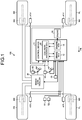
- FIG. 1 is a schematic diagram illustrating an exemplary configuration of a vehicle according to the embodiment.
- a vehicle 100 may be, for example, an automobile (internal combustion engined automobile) using an internal combustion engine (engine 20) as a driving source, an automobile (such as an electric vehicle or a fuel-cell vehicle) using an electric motor (motor, which is not illustrated) as the driving source, or an automobile (hybrid automobile) using both an internal combustion engine and an electric motor as driving sources.
- the vehicle 100 can be equipped with various types of transmissions and various types of devices (such as systems and components) needed for driving the internal combustion engine or the electric motor. For example, systems, numbers, and layouts of devices for driving wheels on the vehicle can be variously set.
- the vehicle 100 is a four-wheel vehicle (four-wheel automobile), and includes two left and right front wheels FL and FR and two left and right rear wheels RL and RR.
- the front side in a vehicle front-rear direction (arrow FB) corresponds to the left side in FIG. 1 .
- the vehicle 100 of the present embodiment includes an engine 20, a brake controller 30, an imaging device 51, a radar 52, a brake switch 42, an accelerator pedal stroke sensor 44, a front-rear directional acceleration sensor 43, and a control device 40.
- the vehicle 100 also includes wheel cylinders Wfr and Wfl and wheel speed sensors 41fr and 41fl corresponding to the two front wheels FR and FL, respectively, and includes wheel cylinders Wrr and Wrl and wheel speed sensors 41rr and 41rl corresponding to the two rear wheels RR and RL, respectively.
- the wheel speed sensors 41fr, 41fl, 41rr, and 41rl may be collectively referred to as wheel speed sensors 41
- the wheel cylinders Wfr, Wfl, Wrr, and Wrl may be collectively referred to as wheel cylinders W.
- vehicle 100 includes basic components as the vehicle 100 in addition to the components illustrated in FIG. 1 , description will herein be given of only relevant configurations of the vehicle 100 and control over the configurations.
- the imaging device 51 is, for example, a digital camera incorporating an image pickup device, such as a charge-coupled device (CCD) or a complementary metal-oxide semiconductor (CMOS) image sensor (CIS).
- the imaging device 51 can output image data (moving image data or frame data) at a certain frame rate.
- the imaging device 51 is located at a front-side end (end in a plan view) (front side in the vehicle front-rear direction) of a vehicle body (not illustrated), and can be provided, for example, on a front bumper.
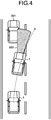
- the imaging device 51 outputs image data including an object to be avoided, such as a preceding vehicle 501 ahead of the vehicle 100 (refer to FIG. 4 ).
- the image data is an example of data from which the object to be avoided is to be detected.
- the radar 52 is, for example, a millimeter-wave radar.
- the radar 52 can output, for example, distance data indicating the distance (separation or detected distance (refer to FIG. 4 )) to the object to be avoided such as the preceding vehicle 501, and velocity data indicating relative speed (velocity) to the object to be avoided.
- the control device 40 updates results of measuring the distance by the radar 52 between the vehicle 100 and the object to be avoided as the preceding vehicle 501, and stores the updated results in a storage at appropriate times (for example, at certain time intervals). The updated distance measurements can be used for calculation.
- Each of the wheel speed sensors 41 outputs a pulse signal upon every rotation of the corresponding wheel by a certain angle.
- the accelerator pedal stroke sensor 44 is provided for an accelerator pedal AP to detect the stroke of the accelerator pedal AP by the driver.
- the brake switch 42 is provided for a brake pedal BP to output a brake operation signal indicating operation or non-operation to the brake pedal BP by the driver. Specifically, the brake switch 42 outputs an ON (High) brake operation signal when the brake pedal BP is operated, and outputs an OFF (Low) brake operation signal when the brake pedal BP is not operated.
- the front-rear directional acceleration sensor 43 detects the acceleration of the vehicle body in the front-rear direction (front-rear acceleration), and outputs a signal representing a front-rear acceleration Gx.
- the engine 20 outputs power in accordance with the operation of the accelerator pedal AP by the driver.
- the brake controller 30 controls the wheels FR, FL, RR, and RL to generate braking forces with brake fluid pressure.
- the brake controller 30 produces the brake fluid pressure corresponding to an operating force applied to the brake pedal BP, and can adjust the supply of the brake fluid pressure to the wheel cylinders Wfr, Wfl, Wrr, and Wrl disposed for the wheels FR, FL, RR, and RL, respectively.
- the control device 40 receives signals and data from the respective elements of the vehicle 100 to control them.
- the control device 40 mainly includes a collision avoidance electronic control unit (ECU) 60, the brake ECU 12, and an engine ECU 13.
- the control device 40 is an example of a collision avoidance device.
- the engine ECU 13 handles various types of control of the engine 20, including fuel injection control and air-intake adjustment control.
- the brake ECU 12 handles, for example, braking torque adjustment control over the vehicle and each of the wheels FR, FL, RR, and RL.
- the brake ECU 12 calculates, for example, the vehicle-body speed of the vehicle based on a detection signal from at least one of the wheel speed sensors 41 provided for the respective wheels FR, FL, RR, and RL, and the deceleration of the vehicle based on a detection signal from the front-rear directional acceleration sensor 43, and transmits the resultants to the other ECUs.
- the deceleration as calculated herein exhibits a positive value while the vehicle is decelerating and exhibits a negative value while the vehicle is accelerating.
- the brake ECU 12 performs an acceleration limiting function to limit the vehicle-body speed to a certain upper limit speed or below.
- the acceleration limiting function is also called an active speed limiter (ASL).
- ASL active speed limiter
- the brake ECU 12 At the start of the acceleration limiting function, notifies the collision avoidance ECU 60 of the execution of the acceleration limiting function.
- the brake ECU 12 At the end of the acceleration limiting function, notifies the collision avoidance ECU 60 of the completion of the acceleration limiting function.
- the collision avoidance ECU 60 sets an execution flag of the acceleration limiting function to ON, and stores it in a storage 65.
- the collision avoidance ECU 60 sets the execution flag of the acceleration limiting function to OFF in the storage 65.
- the collision avoidance ECU 60 controls a collision avoidance function to execute.
- the details of the collision avoidance ECU 60 will be described later.
- Each of the ECUs is configured as a computer, and includes an arithmetic processor (not illustrated) such as a central processing unit (CPU), and a storage (storage 65 in the collision avoidance ECU 60) including a read-only memory (ROM), a random access memory (RAM), or a flash memory.
- the arithmetic processor reads a program stored (installed) in a nonvolatile storage (such as a ROM or a flash memory), executes calculations according to the program, and serves as each of the ECUs.
- a nonvolatile storage such as a ROM or a flash memory
- the collision avoidance ECU 60 functions (operates) as the respective elements illustrated in FIG. 2 (to be described later).
- the storage can store, for example, data (such as tables (data groups) and functions) used in various calculations for the controls, and results of calculations (including values under calculation).
- the configuration of the vehicle 100 described above is merely an example, and can be modified in various forms. Known devices can be used as the individual units of the vehicle 100. The elements of the vehicle 100 can be shared with each other. The vehicle 100 can include a sonar to detect the object to be avoided.
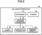
- FIG. 2 is a block diagram illustrating an exemplary functional configuration of the collision avoidance ECU 60 according to the present embodiment.
- the collision avoidance ECU 60 of the present embodiment can function (operate) as a determiner 61, a collision avoidance controller 66, an alarm controller 62, a notification controller 63, and an avoidance braking controller 64, as illustrated in FIG. 2 , through cooperation between hardware and software (program). That is, the program can include modules corresponding to the blocks excluding the storage 65, illustrated in FIG. 2 , as an example.
- the alarm controller 62, the notification controller 63, and the avoidance braking controller 64 are examples of a collision avoidance executor.
- the storage 65 stores, for example, various thresholds, a reference time T1, and various flags (to be described later).
- the collision avoidance controller 66 controls execution of the collision avoidance function.
- the collision avoidance function is a function to maintain a certain relative distance between the preceding vehicle as the object to be avoided and the vehicle so as to avoid collision with the preceding vehicle.
- the collision avoidance function specifically includes avoidance braking, notifying, and alarming.
- the avoidance braking is also called automatic braking to apply a brake to the vehicle 100 with the brake ECU 12 and the brake controller 30 to maintain the relative distance between the preceding vehicle and the vehicle 100.
- the notifying is outputs of sound from a speaker (not illustrated) provided, for example, ahead of the driver's seat, indicating that the avoidance braking is to be activated.
- the alarming is outputs of sound from the speaker (not illustrated), urging the activation of the avoidance braking.
- the notifying and the alarming differ in output sound.
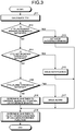
- FIG. 3 is a flowchart of a procedure of executing the collision avoidance function according to the present embodiment.
- the collision avoidance controller 66 calculates a time to collision TTC as an estimated time to collision with the preceding vehicle (S11).
- V AB denotes the relative speed of the vehicle with respect to the preceding vehicle.
- X AB denotes the relative distance from the vehicle to the preceding vehicle.
- ⁇ AB denotes the relative acceleration of the vehicle with respect to the preceding vehicle.
- the collision avoidance controller 66 can calculate V AB based on a result of the detection by any of the wheel speed sensors 41.
- the collision avoidance controller 66 can calculate ⁇ AB based on a result of the detection by the front-rear directional acceleration sensor 43.
- the collision avoidance controller 66 can calculate X AB based on a result of the detection by the radar 52.
- the collision avoidance controller 66 determines whether the time to collision TTC is equal to or smaller than a certain avoidance braking threshold (S12). When determining that the time to collision TTC is equal to or smaller than the avoidance braking threshold (Yes at S12), the collision avoidance controller 66 transmits an avoidance braking command to the avoidance braking controller 64 to activate the avoidance braking (S13). That is, upon receiving the command, the avoidance braking controller 64 instructs the brake ECU 12 to apply a brake. Thus, the brake controller 30 applies braking.
- the collision avoidance controller 66 determines whether the time to collision TTC is equal to or smaller than a certain notification threshold (S14).
- the notification threshold is higher than the avoidance braking threshold. Determining that the time to collision TTC is equal to or smaller than the notification threshold (Yes at S14), the collision avoidance controller 66 transmits a notification command to the notification controller 63 to issue a notification (S15). That is, the notification controller 63 outputs a message of activation of the avoidance braking from the speaker.
- the collision avoidance controller 66 determines whether the time to collision TTC is equal to or smaller than a certain alarm threshold (S16). The alarm threshold is higher than the notification threshold. Determining that the time to collision TTC is equal to or smaller than the alarm threshold (Yes at S16), the collision avoidance controller 66 transmits an alarm command to the alarm controller 62 to issue an alarm (S17). That is, the alarm controller 62 outputs a message of an urgent need for the avoidance braking from the speaker.
- the collision avoidance controller 66 determines whether to continue the alarm, the notification, or the avoidance braking (step S18).
- the continuance determination on the alarm, the notification, or the avoidance braking is a process to determine whether to continue the control of the alarm, the notification, or the avoidance braking when the time to collision TTC is increased by, for example, a deceleration of the vehicle or an advance of the preceding vehicle.
- the collision avoidance controller 66 determines whether to inhibit or end the execution of the collision avoidance function (S19). This determination is a process to determine whether to inhibit or end the execution of the collision avoidance function including the alarming, the notifying, and the avoidance braking based on the operation of the accelerator pedal AP.
- the inhibiting or ending process of the collision avoidance function is also called an accelerator override process.
- the collision avoidance controller 66 controls the relevant controllers to inhibit the execution of the collision avoidance function (alarm, notification, or avoidance braking). In this case, the collision avoidance controller 66 does not transmit an execution command to the alarm controller 62, the notification controller 63, and the avoidance braking controller 64 regardless of the value of the time to collision TTC.
- the collision avoidance controller 66 stores, as a flag, information indicating which item of the collision avoidance function, that is, alarming, notifying, or avoidance braking is activated in the storage 65. The determiner 61 determines whether the avoidance braking is working, with reference to the flag in the storage 65.
- FIG. 4 is a schematic diagram illustrating an example of overtaking the preceding vehicle in the present embodiment.
- the driver steps on the accelerator pedal AP for acceleration, aiming to overtake or slip by the preceding vehicle 501.
- the vehicle 1 decreases the inter-vehicle distance to the preceding vehicle 501 and the time to collision TTC.
- the collision avoidance function (alarm, notification, or avoidance braking) is activated. That is, the time to collision TTC falls to the threshold or less, which activates the collision avoidance function and hinders the vehicle 1 from overtaking or slipping by the preceding vehicle 501, contrary to the driver's intention.
- the collision avoidance controller 66 when determining that the driver clearly intends to accelerate, the collision avoidance controller 66 does not activate the collision avoidance function (alarm, notification, or avoidance braking) so as to allow the vehicle 1 to overtake or slip by the preceding vehicle 501.
- the stroke of the accelerator pedal AP at or above the first threshold is a reference for determining the clear intention of acceleration.
- the reference for determination of the intention of acceleration is not limited thereto.
- the collision avoidance controller 66 refrains from ending the execution of the collision avoidance function until the deceleration stops rising after the start of the avoidance braking. Specifically, the collision avoidance controller 66 does not end the execution of the collision avoidance function (alarm, notification, or avoidance braking) in principle until a certain threshold time T1 elapses from the start of the avoidance braking.
- the threshold time T1 corresponds to a length of time from the start of the avoidance braking to the driver's additional step-on to the accelerator pedal AP due to inertia caused by the deceleration by braking. Such a time is measured in advance and stored as the threshold time T1 in the storage 65.
- An operation of the accelerator pedal AP immediately after the start of the avoidance braking may be a driver's accidental step-on due to the inertia caused by the deceleration because the avoidance braking decelerates the vehicle 100.
- the collision avoidance controller 66 refrains from ending the execution of the collision avoidance function until the threshold time T1 elapses from the start of the collision avoidance function, even when detecting a stroke not exceeding the maximum stroke value of the accelerator pedal AP due to the inertia of the deceleration.
- the collision avoidance controller 66 prevents the executed collision avoidance function from ending by the operation of the accelerator pedal AP caused by the inertia of the deceleration by the braking after the start of the avoidance braking.
- the collision avoidance controller 66 ends the execution of the collision avoidance function (alarm, notification, or avoidance braking). That is, in this case, the collision avoidance controller 66 transmits an execution end command to the alarm controller 62, the notification controller 63, and the avoidance braking controller 64.
- the third threshold is a threshold for determining an accidental step-on to the accelerator pedal AP.
- the third threshold should not be limited as long as it is equal to or greater than the maximum stroke value caused by the inertia of the deceleration.
- the maximum stroke value caused by the inertia of the deceleration is measured in advance and set and stored as the third threshold in the storage 65.
- the third threshold is, however, not limited to this value.
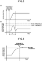
- FIG. 5 depicts diagrams illustrating an example of temporal changes in deceleration and accelerator pedal stroke from the start of the avoidance braking in the present embodiment.
- Horizontal axes in FIG. 5 represent time.
- the graph of FIG. 5(a) illustrates a temporal change in deceleration from the start of the avoidance braking
- the graph of FIG. 5(b) illustrates a temporal change in accelerator pedal stroke from the start of the avoidance braking.
- the threshold time T1 denotes the time taken for gradually increasing deceleration to reach and maintain a certain value of deceleration G from the start of the avoidance braking (in rising state).
- the accelerator pedal AP is depressed by the inertia caused by the deceleration before the threshold time T1 elapses.
- the collision avoidance controller 66 does not, however, end (cancel) the execution of the collision avoidance function unless the stroke exceeds the third threshold.
- the determiner 61 determines, based on the operation of the accelerator pedal AP by the driver, whether the driver clearly intends to cancel the collision avoidance function. Specifically, the determiner 61 receives, from the accelerator pedal stroke sensor 44, the stroke of the accelerator pedal AP detected by the accelerator pedal stroke sensor 44. When determining that the stroke of the accelerator pedal AP is equal to or greater than a second threshold, when two or more depressions of the accelerator pedal AP is detected within a certain period of time, or when the speed of depression of the accelerator pedal AP is equal to or greater than a certain speed threshold, the determiner 61 determines that the driver clearly intends to cancel the collision avoidance function.
- the collision avoidance controller 66 ends the execution of the collision avoidance function (alarm, notification, or avoidance braking). That is, in this case, the collision avoidance controller 66 transmits the execution end command to the alarm controller 62, the notification controller 63, and the avoidance braking controller 64.
- the collision avoidance controller 66 when determining, through the operation of the accelerator pedal AP, the driver's clear intention to cancel the collision avoidance function, the collision avoidance controller 66 ends the execution of the collision avoidance function (alarm, notification, or avoidance braking). Thereby, even in continuation of the collision avoidance function, the vehicle can be driven to overtake the preceding vehicle for avoiding collision with the preceding vehicle or the following vehicle.
- FIG. 6 is a diagram for explaining the clear intention of cancelation represented by the stroke of the accelerator pedal AP in the present embodiment.
- FIG. 6 illustrates the accelerator pedal stroke during the avoidance braking, where the horizontal axis represents time, and the vertical axis represents the accelerator pedal stroke.
- the second threshold is set to the operation amount (stroke) of the accelerator pedal AP which is beyond the amount by a normal operation of the driver during the deceleration control through the avoidance braking
- the second threshold may be set to a value other than the maximum stroke of 100%, taking into consideration the behavior of the vehicle 100 after the braking cancellation, for example.
- the first threshold under the condition in which the engine of the vehicle has low driving torque or the vehicle is placed in a gear with a small reduction ratio, the operation amount of the accelerator pedal AP by the driver is large during acceleration. Therefore, the first threshold is set to a relatively greater value than that under conditions other than the above-described condition.
- the third threshold under the condition such as a small change in deceleration caused by the collision avoidance, a large reaction force to the accelerator pedal AP, or a large stroke amount of the accelerator pedal AP from the fully closed throttle position to the full throttle position, the accelerator position (the stroke of the accelerator pedal AP) of an erroneously operated accelerator pedal is small. Therefore, the third threshold is set to be a relatively smaller value than that under conditions other than the above-described condition.
- the relation of magnitude between the first threshold and the third threshold can be such that the third threshold ⁇ the first threshold, unlike the present embodiment.
- the execution of the collision avoidance function can be ended according to the second threshold over the entire range after start of the deceleration control by the avoidance braking.
- the second threshold and the third threshold are preferably set such that the second threshold > the third threshold.
- the execution of the collision avoidance function can be ended outside the threshold time T1 according to the second threshold.
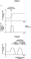
- FIG. 7 depicts diagrams for explaining the clear intention of cancelation represented by the depression speed of the accelerator pedal AP in the present embodiment.
- FIG. 7 illustrates the accelerator pedal stroke and the accelerator pedal depression speed during the avoidance braking.
- the graph of FIG. 7(a) illustrates a temporal change in accelerator pedal stroke
- the graph of FIG. 7(b) illustrates a temporal change in accelerator pedal depression speed.
- the change rate of the accelerator pedal stroke reaches or exceeds a certain gradient as illustrated in the graph of FIG. 7(a)
- the accelerator pedal depression speed reaches or exceeds the certain speed threshold as illustrated in the graph of FIG.
- the determiner 61 determines the driver's clear intention to cancel the collision avoidance function, and the collision avoidance controller 66 ends the execution of the avoidance braking.
- the accelerator pedal depression speed is calculated from the change amount in the stroke of the accelerator pedal AP.
- FIG. 8 is a diagram for explaining the clear intention of cancelation represented by the number of depressions of the accelerator pedal AP in the present embodiment.
- FIG. 8 illustrates the stroke of the accelerator pedal AP during the avoidance braking, where the horizontal axis represents time, and the vertical axis represents the accelerator pedal stroke.
- a detection signal is received from the accelerator pedal stroke sensor 44. When the stroke represented by the detection signal is greater than zero, the operation of the accelerator pedal AP is determined and counted as one depression.
- the determiner 61 determines, upon detecting a second-time depression, the clear intention to cancel the avoidance braking, and the collision avoidance controller 66 ends the avoidance braking.
- the depression count threshold is set to two in the example of FIG. 8
- the depression count threshold can be set to three or more.
- the depression count threshold can be set to one under a combination of the condition for determining the clear intention of cancelation with a condition for limiting the detection period or state such as continuation of the stroke of the accelerator pedal AP at 0% for a certain time or longer or the elapse of a certain time from the avoidance braking.
- the condition for limiting the detection period or state may additionally include no depression of the brake pedal BP and operation of the steering wheel.
- the clear intention of cancelation is determined in the three situations, that is, that the stroke of the accelerator pedal AP is equal to or greater than the second threshold, that two or more depressions of the accelerator pedal AP are detected within the certain period of time, and that the depression speed of the accelerator pedal AP is equal to or greater than the speed threshold.
- the present embodiment is, however, not limited to these three situations.
- the determiner 61 determines, with reference to the execution flag of the acceleration limiting function in the storage 65, whether the brake ECU 12 is executing the acceleration limiting function.
- the collision avoidance controller 66 controls the relevant controllers so as not to inhibit or end the execution of the collision avoidance function, regardless of the operation of the accelerator pedal AP detected by the accelerator pedal stroke sensor 44, that is, even when detecting the operation of the accelerator pedal AP indicating the clear intention of acceleration or cancelation thereof.
- the operation of the accelerator pedal AP is not consistent with the speed and the acceleration of the vehicle 100, and the driver may differently operate the accelerator pedal AP from a normal operation.
- the driver does not feel acceleration, which makes it difficult to determine the clear intention of acceleration of the driver from the stroke of the accelerator pedal AP.
- the present embodiment refrains from inhibiting or ending the collision avoidance function during the control of the acceleration limiting function, even when detecting the operation of the accelerator pedal AP. Thereby, erroneous determination on the inhibition or ending of the collision avoidance function is prevented.
- FIG. 9 depicts diagrams illustrating temporal changes in vehicle speed, accelerator pedal stroke, and acceleration of the vehicle during the control of the acceleration limiting function according to the present embodiment.
- FIG. 9(a) illustrates a temporal change in speed of the vehicle.
- FIG. 9(b) illustrates a temporal change in accelerator pedal stroke of the vehicle.
- FIG. 9(c) illustrates a temporal change in acceleration of the vehicle.
- the vehicle speed is limited to the upper limit speed even with an increase in the stroke of the accelerator pedal AP.
- the acceleration of the vehicle 100 increases under normal circumstances as indicated by the dotted line in FIG. 9(c) .
- the acceleration decreases as indicated by the solid line in FIG. 9(c) .
- the stroke of the accelerator pedal AP being the first threshold or above cannot be determined as the clear intention of acceleration since the vehicle body speed and the acceleration are limited.
- the determiner 61 receives the brake operation signal from the brake switch 42 to determine whether the brake pedal BP is operated from ON or OFF of the brake operation signal.
- the determiner 61 receives the detection signal from the accelerator pedal stroke sensor 44 to determine that the accelerator pedal AP is operated, when the stroke represented by the detection signal is greater than zero, as described above.
- the collision avoidance controller 66 controls the relevant controllers so as not to inhibit or end the execution of the collision avoidance function, regardless of the operation of the accelerator pedal AP detected by the accelerator pedal stroke sensor 44.
- the depression of both the accelerator pedal AP and the brake pedal BP generally signifies an unusual situation that the driver accidentally touches the accelerator pedal AP while depressing the brake pedal BP.
- the execution of the collision avoidance function is not inhibited or ended by the operation of the accelerator pedal AP by the driver.
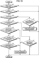
- FIG. 10 is a flowchart of an exemplary procedure of the inhibition or ending determination on the execution of the collision avoidance function according to the present embodiment.
- the process in FIG. 10 is executed individually when the avoidance braking is activated at S13 of FIG. 3 , when the notification is issued at S15 of FIG. 3 , and when the alarm is issued at S17 of FIG. 3 .
- the determiner 61 determines, with reference to the execution flag of the acceleration limiting function in the storage 65, whether the acceleration limiting function is being executed by, for example, the brake ECU 12 (S31). When determining that the acceleration limiting function is being executed (Yes at S31), the determiner 61 ends the process. As a result, the collision avoidance function is not inhibited or ended, regardless of the operation of the accelerator pedal AP.
- the determiner 61 determines whether the brake operation signal output from the brake switch 42 is ON to thereby determine detection or non-detection of the operation of the brake pedal BP (S32).
- the determiner 61 ends the process. Thereby, the execution of the collision avoidance function is not inhibited or ended, which means that the operation of the brake pedal BP is given a higher priority than that of the driver's operation of the accelerator pedal AP.
- the determiner 61 determines, with reference to the flag in the storage 65, whether the avoidance braking (automatic braking) is working (S33). When determining that avoidance braking is not working (No at S33), the determiner 61 determines, based on the detection signal from the accelerator pedal stroke sensor 44, whether the stroke of the accelerator pedal AP is equal to or greater than the first threshold (that is, whether the vehicle is accelerating) (S34).
- the determiner 61 determines that the driver clearly intends to accelerate, and the collision avoidance controller 66 ends the alarm or the notification if they are issued, or inhibits the issuance of the alarm or the notification if they are not issued.
- the collision avoidance controller 66 inhibits the activation of the avoidance braking (S35). Then, the process ends.
- the determiner 61 determines whether the threshold time T1 has elapsed from the start of the avoidance braking, that is, whether the deceleration has stopped rising (S36).
- the determiner 61 determines, from the detection signal from the accelerator pedal stroke sensor 44, whether the stroke of the accelerator pedal AP is equal to or greater than the third threshold (that is, whether it exceeds the stroke caused by the inertia of the deceleration) (S37).
- the collision avoidance controller 66 ends the alarm or the notification, or the avoidance braking (S41).
- the determiner 61 determines whether the stroke of the accelerator pedal AP is equal to or greater than the second threshold (that is, whether the vehicle is accelerating at a full throttle) (S38). Upon determining the stroke of the accelerator pedal AP as equal to or greater than the second threshold (Yes at S38), the determiner 61 determines the driver's clear intention to cancel the collision avoidance function, and the collision avoidance controller 66 ends the alarm or the notification, or the avoidance braking (S41) .
- the determiner 61 determines, based on the detection signals from the accelerator pedal stroke sensor 44, whether the accelerator pedal AP has been depressed two or more times within the certain period of time (S39). Upon determining two or more depressions of the accelerator pedal AP within the certain period of time (Yes at S39), the determiner 61 determines that the driver clearly intends to cancel the execution of the collision avoidance function, and the collision avoidance controller 66 ends the alarm, the notification, or the avoidance braking (S41).
- the determiner 61 determines, from the detection signal from the accelerator pedal stroke sensor 44, whether the depression speed of the accelerator pedal AP is equal to or greater than the speed threshold (S40). When determining the depression speed of the accelerator pedal AP as equal to or greater than the speed threshold (Yes at S40), the determiner 61 determines the driver's clear intention to cancel the execution of the collision avoidance function, and the collision avoidance controller 66 ends the alarm, the notification, or the avoidance braking (S41).
- the collision avoidance controller 66 controls the respective controllers to inhibit the activation of the collision avoidance function (alarm, notification, or avoidance braking).
- the vehicle equipped with the collision avoidance function can travel according to or reflecting the driver's intention, that is, can overtake or slip by the preceding vehicle.
- the collision avoidance controller 66 does not end the collision avoidance function from the start of the avoidance braking to the stop of rising of the deceleration. Because of this, even when the inertia by the deceleration of the vehicle 100 by the avoidance braking causes the driver to additionally step on the accelerator pedal AP by accident, the collision avoidance function is not ended, and thus, the collision avoidance function can be securely executed.
- the collision avoidance controller 66 ends the execution of the collision avoidance function (alarm, notification, or avoidance braking).
- the driver can intentionally end the collision avoidance function, for example, even before the rising of the deceleration after the start of the avoidance braking.
- the collision avoidance controller 66 ends the execution of the collision avoidance function (alarm, notification, or avoidance braking).
- the present embodiment enables the vehicle to run as the driver intends, for example, to overtake the preceding vehicle for avoiding the collision with the preceding vehicle or the following vehicle even during the continuation of the avoidance braking.
- the present embodiment during the control of the executed acceleration limiting function for limiting the speed and the acceleration of the vehicle 100, the execution of the collision avoidance function is not inhibited or ended even upon detection of the operation of the accelerator pedal AP.
- the present embodiment can prevent, for example, erroneous determination on the inhibition or ending of the collision avoidance function.
- the relevant controllers when determining simultaneous operations of the brake pedal BP and the accelerator pedal AP, do not inhibit or end the collision avoidance function regardless of the operation of the accelerator pedal AP.
- the collision avoidance function is not inhibited or ended by the driver's operation of the accelerator pedal AP, which can prioritize the deceleration over the acceleration.
Landscapes
- Engineering & Computer Science (AREA)
- Mechanical Engineering (AREA)
- Transportation (AREA)
- Combustion & Propulsion (AREA)
- Chemical & Material Sciences (AREA)
- Automation & Control Theory (AREA)
- Human Computer Interaction (AREA)
- Physics & Mathematics (AREA)
- General Physics & Mathematics (AREA)
- Radar, Positioning & Navigation (AREA)
- Remote Sensing (AREA)
- Regulating Braking Force (AREA)
- Control Of Driving Devices And Active Controlling Of Vehicle (AREA)
- Traffic Control Systems (AREA)
Applications Claiming Priority (2)
| Application Number | Priority Date | Filing Date | Title |
|---|---|---|---|
| JP2014242294A JP6166242B2 (ja) | 2014-11-28 | 2014-11-28 | 衝突回避装置 |
| PCT/JP2015/083506 WO2016084967A1 (ja) | 2014-11-28 | 2015-11-27 | 衝突回避装置 |
Publications (3)
| Publication Number | Publication Date |
|---|---|
| EP3225486A1 EP3225486A1 (en) | 2017-10-04 |
| EP3225486A4 EP3225486A4 (en) | 2018-01-10 |
| EP3225486B1 true EP3225486B1 (en) | 2021-09-29 |
Family
ID=56074512
Family Applications (1)
| Application Number | Title | Priority Date | Filing Date |
|---|---|---|---|
| EP15863734.8A Active EP3225486B1 (en) | 2014-11-28 | 2015-11-27 | Collision avoidance device |
Country Status (5)
| Country | Link |
|---|---|
| US (1) | US10384629B2 (ja) |
| EP (1) | EP3225486B1 (ja) |
| JP (1) | JP6166242B2 (ja) |
| CN (1) | CN107000743B (ja) |
| WO (1) | WO2016084967A1 (ja) |
Families Citing this family (24)
| Publication number | Priority date | Publication date | Assignee | Title |
|---|---|---|---|---|
| JP6413955B2 (ja) * | 2015-06-30 | 2018-10-31 | 株式会社デンソー | 逸脱回避装置 |
| JP6485328B2 (ja) * | 2015-11-09 | 2019-03-20 | 株式会社デンソー | 車両の運転支援装置 |
| JP6369477B2 (ja) * | 2016-01-07 | 2018-08-08 | トヨタ自動車株式会社 | 運転支援装置 |
| GB2554759B (en) | 2016-10-10 | 2020-02-19 | Jaguar Land Rover Ltd | Control of a vehicle emergency braking system |
| WO2018182747A1 (en) * | 2017-04-01 | 2018-10-04 | Intel Corporation | Automotive analytics technology to provide synergistic collision safety |
| JP6822306B2 (ja) * | 2017-05-11 | 2021-01-27 | トヨタ自動車株式会社 | 運転支援装置 |
| JP6791021B2 (ja) * | 2017-06-06 | 2020-11-25 | トヨタ自動車株式会社 | 操舵支援装置 |
| JP6972744B2 (ja) | 2017-08-01 | 2021-11-24 | トヨタ自動車株式会社 | 運転支援装置 |
| JP6939322B2 (ja) * | 2017-09-25 | 2021-09-22 | トヨタ自動車株式会社 | 運転支援装置 |
| JP7087432B2 (ja) * | 2018-02-16 | 2022-06-21 | マツダ株式会社 | 車両の制御装置 |
| JP7035753B2 (ja) | 2018-04-16 | 2022-03-15 | トヨタ自動車株式会社 | 運転支援装置 |
| CN108819928B (zh) * | 2018-05-25 | 2019-10-18 | 北京车和家信息技术有限公司 | 控制车辆运行的方法及装置 |
| JP7103050B2 (ja) * | 2018-08-08 | 2022-07-20 | 株式会社デンソー | 車両制御装置 |
| KR102637599B1 (ko) * | 2018-10-08 | 2024-02-19 | 주식회사 에이치엘클레무브 | 차량간 통신 정보를 이용한 차선변경 제어장치 및 방법과, 그를 위한 성향 정보 산출 장치 |
| JP7035995B2 (ja) * | 2018-12-25 | 2022-03-15 | トヨタ自動車株式会社 | 運転支援装置 |
| KR102658055B1 (ko) * | 2019-05-14 | 2024-04-17 | 현대모비스 주식회사 | 조향 회피 경로를 고려한 적응형 aeb 시스템 및 그 제어 방법 |
| JP7140077B2 (ja) * | 2019-09-02 | 2022-09-21 | トヨタ自動車株式会社 | 衝突回避支援装置 |
| JP7327032B2 (ja) * | 2019-09-19 | 2023-08-16 | スズキ株式会社 | 車両制御装置 |
| JP7147733B2 (ja) * | 2019-11-22 | 2022-10-05 | トヨタ自動車株式会社 | 衝突回避支援装置 |
| CN111152788B (zh) * | 2019-12-26 | 2021-08-10 | 的卢技术有限公司 | 一种车辆油门踏板误踩预防方法和系统 |
| US11433915B2 (en) * | 2020-08-28 | 2022-09-06 | Toyota Research Institute, Inc. | Determining an action to be performed by a vehicle in response to conflicting input signals |
| JP7498648B2 (ja) | 2020-11-13 | 2024-06-12 | 株式会社Subaru | 制動制御装置 |
| DE102021114530A1 (de) | 2021-06-07 | 2022-12-08 | Bayerische Motoren Werke Aktiengesellschaft | Verfahren und vorrichtung zum betrieb eines notbremsassistenten für ein fahrzeug |
| KR20230013222A (ko) * | 2021-07-16 | 2023-01-26 | 현대자동차주식회사 | 전방 차량과의 차간 거리 제어 장치 및 방법 |
Family Cites Families (20)
| Publication number | Priority date | Publication date | Assignee | Title |
|---|---|---|---|---|
| JPS5269132A (en) | 1975-12-08 | 1977-06-08 | Nissan Motor Co Ltd | Collision preventing apparatus |
| JP3325590B2 (ja) * | 1991-08-07 | 2002-09-17 | マツダ株式会社 | 車両の自動制動装置 |
| JP3697556B2 (ja) | 1994-03-16 | 2005-09-21 | アイシン精機株式会社 | 車両制動装置 |
| US6016543A (en) * | 1997-05-14 | 2000-01-18 | Mitsubishi Denki Kabushiki Kaisha | Microprocessor for controlling the conditional execution of instructions |
| JP4318505B2 (ja) * | 2003-08-06 | 2009-08-26 | ダイハツ工業株式会社 | 衝突回避装置 |
| JP2005082041A (ja) * | 2003-09-09 | 2005-03-31 | Toyota Motor Corp | 車両用自動ブレーキ装置 |
| JP3988732B2 (ja) | 2004-03-09 | 2007-10-10 | 日産自動車株式会社 | 車両用運転操作補助装置および車両用運転操作補助装置を備えた車両 |
| JP2006117188A (ja) * | 2004-10-25 | 2006-05-11 | Toyota Motor Corp | 車両制御装置 |
| JP5042128B2 (ja) * | 2008-06-10 | 2012-10-03 | Udトラックス株式会社 | 衝突被害軽減装置 |
| JP5353289B2 (ja) | 2009-02-19 | 2013-11-27 | 日産自動車株式会社 | 運転操作支援装置及び運転操作支援方法 |
| DE102009057836B4 (de) * | 2009-12-10 | 2013-02-21 | Continental Teves Ag & Co. Ohg | Notbremsassistenzsystem zur Unterstützung eines Fahrers eines Fahrzeugs beim Anfahren |
| DE102010049351A1 (de) * | 2010-10-23 | 2012-04-26 | Daimler Ag | Verfahren zum Betreiben einer Bremsassistenzvorrichtung und Bremsassistenzvorrichtung für ein Fahrzeug |
| JP2012121534A (ja) | 2010-12-10 | 2012-06-28 | Daimler Ag | 車両の自動制動装置 |
| JP5724569B2 (ja) | 2011-04-15 | 2015-05-27 | トヨタ自動車株式会社 | 車両用制動制御装置 |
| DE102011081707A1 (de) * | 2011-08-29 | 2013-02-28 | Robert Bosch Gmbh | Verfahren zur Unterstützung eines Fahrers eines Kraftfahrzeugs |
| DE102012202294A1 (de) * | 2012-02-15 | 2013-08-22 | Robert Bosch Gmbh | Verfahren und Kontrollsystem zur Plausibilisierung eines ersten Fahrerwunschsensors in Bezug auf einen zweiten zum ersten unterschiedlichen Fahrerwunschsensor eines Kraftfahrzeugs |
| JP5867302B2 (ja) * | 2012-06-13 | 2016-02-24 | 株式会社アドヴィックス | 車両の走行支援装置 |
| DE112012006878T5 (de) * | 2012-09-04 | 2015-05-21 | Toyota Jidosha Kabushiki Kaisha | Kollisionsvermeidungsunterstützungsvorrichtung und Kollisionsvermeidungsunterstützungsverfahren |
| CN104781867B (zh) * | 2012-11-13 | 2017-06-09 | 丰田自动车株式会社 | 驾驶辅助装置以及驾驶辅助方法 |
| US9493162B2 (en) * | 2013-02-05 | 2016-11-15 | Toyota Jidosha Kabushiki Kaisha | Vehicle control device |
-
2014
- 2014-11-28 JP JP2014242294A patent/JP6166242B2/ja active Active
-
2015
- 2015-11-27 US US15/529,557 patent/US10384629B2/en active Active
- 2015-11-27 WO PCT/JP2015/083506 patent/WO2016084967A1/ja active Application Filing
- 2015-11-27 CN CN201580063870.6A patent/CN107000743B/zh active Active
- 2015-11-27 EP EP15863734.8A patent/EP3225486B1/en active Active
Also Published As
| Publication number | Publication date |
|---|---|
| EP3225486A1 (en) | 2017-10-04 |
| US10384629B2 (en) | 2019-08-20 |
| CN107000743A (zh) | 2017-08-01 |
| US20170341612A1 (en) | 2017-11-30 |
| EP3225486A4 (en) | 2018-01-10 |
| JP2016101891A (ja) | 2016-06-02 |
| CN107000743B (zh) | 2019-03-15 |
| JP6166242B2 (ja) | 2017-07-19 |
| WO2016084967A1 (ja) | 2016-06-02 |
Similar Documents
| Publication | Publication Date | Title |
|---|---|---|
| EP3225486B1 (en) | Collision avoidance device | |
| EP3225472B1 (en) | Collision avoidance device | |
| US11932265B2 (en) | Driving assistance system | |
| KR101814784B1 (ko) | 차량 제어 방법 및 차량 제어 시스템 | |
| EP4071009B1 (en) | Collision avoidance assistance apparatus | |
| US10124776B2 (en) | Brake control device for vehicle | |
| US10434942B2 (en) | Driving assistance device | |
| EP3225474A1 (en) | Collision avoidance device | |
| CN108146433B (zh) | 车辆的紧急自动制动系统及方法 | |
| CN113212425A (zh) | 驾驶辅助装置 | |
| JP2008296887A (ja) | 車両制御装置 | |
| KR101511863B1 (ko) | 타이어 공기압을 고려한 긴급제동 장치 및 그 제어방법 | |
| US20210179039A1 (en) | Braking assistance apparatus for a vehicle | |
| JP7521517B2 (ja) | 車両制御装置、車両、加減速制御方法、及び車両制御プログラム | |
| JP2005329941A (ja) | 車間距離制御装置 | |
| US20240067178A1 (en) | Overtake for an automatic cruise control | |
| JP7387241B2 (ja) | 車両用制御装置 |
Legal Events
| Date | Code | Title | Description |
|---|---|---|---|
| STAA | Information on the status of an ep patent application or granted ep patent |
Free format text: STATUS: THE INTERNATIONAL PUBLICATION HAS BEEN MADE |
|
| PUAI | Public reference made under article 153(3) epc to a published international application that has entered the european phase |
Free format text: ORIGINAL CODE: 0009012 |
|
| STAA | Information on the status of an ep patent application or granted ep patent |
Free format text: STATUS: REQUEST FOR EXAMINATION WAS MADE |
|
| 17P | Request for examination filed |
Effective date: 20170518 |
|
| AK | Designated contracting states |
Kind code of ref document: A1 Designated state(s): AL AT BE BG CH CY CZ DE DK EE ES FI FR GB GR HR HU IE IS IT LI LT LU LV MC MK MT NL NO PL PT RO RS SE SI SK SM TR |
|
| AX | Request for extension of the european patent |
Extension state: BA ME |
|
| A4 | Supplementary search report drawn up and despatched |
Effective date: 20171211 |
|
| RIC1 | Information provided on ipc code assigned before grant |
Ipc: B60W 10/08 20060101ALI20171201BHEP Ipc: B60W 50/14 20120101ALI20171201BHEP Ipc: B60W 50/10 20120101ALI20171201BHEP Ipc: B60W 10/184 20120101ALI20171201BHEP Ipc: B60W 30/18 20120101ALI20171201BHEP Ipc: B60T 7/22 20060101ALI20171201BHEP Ipc: G08G 1/16 20060101ALI20171201BHEP Ipc: B60R 21/00 20060101ALI20171201BHEP Ipc: B60T 7/12 20060101ALI20171201BHEP Ipc: B60W 10/06 20060101ALI20171201BHEP Ipc: B60W 50/12 20120101ALI20171201BHEP Ipc: B60W 30/09 20120101AFI20171201BHEP |
|
| DAV | Request for validation of the european patent (deleted) | ||
| DAX | Request for extension of the european patent (deleted) | ||
| GRAP | Despatch of communication of intention to grant a patent |
Free format text: ORIGINAL CODE: EPIDOSNIGR1 |
|
| STAA | Information on the status of an ep patent application or granted ep patent |
Free format text: STATUS: GRANT OF PATENT IS INTENDED |
|
| INTG | Intention to grant announced |
Effective date: 20210423 |
|
| GRAS | Grant fee paid |
Free format text: ORIGINAL CODE: EPIDOSNIGR3 |
|
| GRAA | (expected) grant |
Free format text: ORIGINAL CODE: 0009210 |
|
| STAA | Information on the status of an ep patent application or granted ep patent |
Free format text: STATUS: THE PATENT HAS BEEN GRANTED |
|
| AK | Designated contracting states |
Kind code of ref document: B1 Designated state(s): AL AT BE BG CH CY CZ DE DK EE ES FI FR GB GR HR HU IE IS IT LI LT LU LV MC MK MT NL NO PL PT RO RS SE SI SK SM TR |
|
| RAP3 | Party data changed (applicant data changed or rights of an application transferred) |
Owner name: TOYOTA JIDOSHA KABUSHIKI KAISHA Owner name: ADVICS CO., LTD. |
|
| REG | Reference to a national code |
Ref country code: GB Ref legal event code: FG4D |
|
| RIN1 | Information on inventor provided before grant (corrected) |
Inventor name: IKE, WATARU Inventor name: OHMORI, YOSUKE |
|
| REG | Reference to a national code |
Ref country code: DE Ref legal event code: R096 Ref document number: 602015073786 Country of ref document: DE |
|
| REG | Reference to a national code |
Ref country code: CH Ref legal event code: EP Ref country code: AT Ref legal event code: REF Ref document number: 1433941 Country of ref document: AT Kind code of ref document: T Effective date: 20211015 |
|
| REG | Reference to a national code |
Ref country code: IE Ref legal event code: FG4D |
|
| REG | Reference to a national code |
Ref country code: LT Ref legal event code: MG9D |
|
| PG25 | Lapsed in a contracting state [announced via postgrant information from national office to epo] |
Ref country code: SE Free format text: LAPSE BECAUSE OF FAILURE TO SUBMIT A TRANSLATION OF THE DESCRIPTION OR TO PAY THE FEE WITHIN THE PRESCRIBED TIME-LIMIT Effective date: 20210929 Ref country code: RS Free format text: LAPSE BECAUSE OF FAILURE TO SUBMIT A TRANSLATION OF THE DESCRIPTION OR TO PAY THE FEE WITHIN THE PRESCRIBED TIME-LIMIT Effective date: 20210929 Ref country code: HR Free format text: LAPSE BECAUSE OF FAILURE TO SUBMIT A TRANSLATION OF THE DESCRIPTION OR TO PAY THE FEE WITHIN THE PRESCRIBED TIME-LIMIT Effective date: 20210929 Ref country code: LT Free format text: LAPSE BECAUSE OF FAILURE TO SUBMIT A TRANSLATION OF THE DESCRIPTION OR TO PAY THE FEE WITHIN THE PRESCRIBED TIME-LIMIT Effective date: 20210929 Ref country code: BG Free format text: LAPSE BECAUSE OF FAILURE TO SUBMIT A TRANSLATION OF THE DESCRIPTION OR TO PAY THE FEE WITHIN THE PRESCRIBED TIME-LIMIT Effective date: 20211229 Ref country code: NO Free format text: LAPSE BECAUSE OF FAILURE TO SUBMIT A TRANSLATION OF THE DESCRIPTION OR TO PAY THE FEE WITHIN THE PRESCRIBED TIME-LIMIT Effective date: 20211229 Ref country code: FI Free format text: LAPSE BECAUSE OF FAILURE TO SUBMIT A TRANSLATION OF THE DESCRIPTION OR TO PAY THE FEE WITHIN THE PRESCRIBED TIME-LIMIT Effective date: 20210929 |
|
| REG | Reference to a national code |
Ref country code: NL Ref legal event code: MP Effective date: 20210929 |
|
| REG | Reference to a national code |
Ref country code: AT Ref legal event code: MK05 Ref document number: 1433941 Country of ref document: AT Kind code of ref document: T Effective date: 20210929 |
|
| PG25 | Lapsed in a contracting state [announced via postgrant information from national office to epo] |
Ref country code: LV Free format text: LAPSE BECAUSE OF FAILURE TO SUBMIT A TRANSLATION OF THE DESCRIPTION OR TO PAY THE FEE WITHIN THE PRESCRIBED TIME-LIMIT Effective date: 20210929 Ref country code: GR Free format text: LAPSE BECAUSE OF FAILURE TO SUBMIT A TRANSLATION OF THE DESCRIPTION OR TO PAY THE FEE WITHIN THE PRESCRIBED TIME-LIMIT Effective date: 20211230 |
|
| PG25 | Lapsed in a contracting state [announced via postgrant information from national office to epo] |
Ref country code: AT Free format text: LAPSE BECAUSE OF FAILURE TO SUBMIT A TRANSLATION OF THE DESCRIPTION OR TO PAY THE FEE WITHIN THE PRESCRIBED TIME-LIMIT Effective date: 20210929 |
|
| PG25 | Lapsed in a contracting state [announced via postgrant information from national office to epo] |
Ref country code: IS Free format text: LAPSE BECAUSE OF FAILURE TO SUBMIT A TRANSLATION OF THE DESCRIPTION OR TO PAY THE FEE WITHIN THE PRESCRIBED TIME-LIMIT Effective date: 20220129 Ref country code: SK Free format text: LAPSE BECAUSE OF FAILURE TO SUBMIT A TRANSLATION OF THE DESCRIPTION OR TO PAY THE FEE WITHIN THE PRESCRIBED TIME-LIMIT Effective date: 20210929 Ref country code: RO Free format text: LAPSE BECAUSE OF FAILURE TO SUBMIT A TRANSLATION OF THE DESCRIPTION OR TO PAY THE FEE WITHIN THE PRESCRIBED TIME-LIMIT Effective date: 20210929 Ref country code: PT Free format text: LAPSE BECAUSE OF FAILURE TO SUBMIT A TRANSLATION OF THE DESCRIPTION OR TO PAY THE FEE WITHIN THE PRESCRIBED TIME-LIMIT Effective date: 20220131 Ref country code: PL Free format text: LAPSE BECAUSE OF FAILURE TO SUBMIT A TRANSLATION OF THE DESCRIPTION OR TO PAY THE FEE WITHIN THE PRESCRIBED TIME-LIMIT Effective date: 20210929 Ref country code: NL Free format text: LAPSE BECAUSE OF FAILURE TO SUBMIT A TRANSLATION OF THE DESCRIPTION OR TO PAY THE FEE WITHIN THE PRESCRIBED TIME-LIMIT Effective date: 20210929 Ref country code: ES Free format text: LAPSE BECAUSE OF FAILURE TO SUBMIT A TRANSLATION OF THE DESCRIPTION OR TO PAY THE FEE WITHIN THE PRESCRIBED TIME-LIMIT Effective date: 20210929 Ref country code: EE Free format text: LAPSE BECAUSE OF FAILURE TO SUBMIT A TRANSLATION OF THE DESCRIPTION OR TO PAY THE FEE WITHIN THE PRESCRIBED TIME-LIMIT Effective date: 20210929 Ref country code: CZ Free format text: LAPSE BECAUSE OF FAILURE TO SUBMIT A TRANSLATION OF THE DESCRIPTION OR TO PAY THE FEE WITHIN THE PRESCRIBED TIME-LIMIT Effective date: 20210929 Ref country code: AL Free format text: LAPSE BECAUSE OF FAILURE TO SUBMIT A TRANSLATION OF THE DESCRIPTION OR TO PAY THE FEE WITHIN THE PRESCRIBED TIME-LIMIT Effective date: 20210929 |
|
| PG25 | Lapsed in a contracting state [announced via postgrant information from national office to epo] |
Ref country code: MC Free format text: LAPSE BECAUSE OF FAILURE TO SUBMIT A TRANSLATION OF THE DESCRIPTION OR TO PAY THE FEE WITHIN THE PRESCRIBED TIME-LIMIT Effective date: 20210929 |
|
| REG | Reference to a national code |
Ref country code: DE Ref legal event code: R097 Ref document number: 602015073786 Country of ref document: DE Ref country code: CH Ref legal event code: PL |
|
| PG25 | Lapsed in a contracting state [announced via postgrant information from national office to epo] |
Ref country code: LU Free format text: LAPSE BECAUSE OF NON-PAYMENT OF DUE FEES Effective date: 20211127 Ref country code: DK Free format text: LAPSE BECAUSE OF FAILURE TO SUBMIT A TRANSLATION OF THE DESCRIPTION OR TO PAY THE FEE WITHIN THE PRESCRIBED TIME-LIMIT Effective date: 20210929 Ref country code: BE Free format text: LAPSE BECAUSE OF NON-PAYMENT OF DUE FEES Effective date: 20211130 |
|
| REG | Reference to a national code |
Ref country code: BE Ref legal event code: MM Effective date: 20211130 |
|
| PLBE | No opposition filed within time limit |
Free format text: ORIGINAL CODE: 0009261 |
|
| STAA | Information on the status of an ep patent application or granted ep patent |
Free format text: STATUS: NO OPPOSITION FILED WITHIN TIME LIMIT |
|
| GBPC | Gb: european patent ceased through non-payment of renewal fee |
Effective date: 20211229 |
|
| 26N | No opposition filed |
Effective date: 20220630 |
|
| PG25 | Lapsed in a contracting state [announced via postgrant information from national office to epo] |
Ref country code: IE Free format text: LAPSE BECAUSE OF NON-PAYMENT OF DUE FEES Effective date: 20211127 Ref country code: GB Free format text: LAPSE BECAUSE OF NON-PAYMENT OF DUE FEES Effective date: 20211229 |
|
| PG25 | Lapsed in a contracting state [announced via postgrant information from national office to epo] |
Ref country code: SI Free format text: LAPSE BECAUSE OF FAILURE TO SUBMIT A TRANSLATION OF THE DESCRIPTION OR TO PAY THE FEE WITHIN THE PRESCRIBED TIME-LIMIT Effective date: 20210929 Ref country code: FR Free format text: LAPSE BECAUSE OF NON-PAYMENT OF DUE FEES Effective date: 20211129 |
|
| PG25 | Lapsed in a contracting state [announced via postgrant information from national office to epo] |
Ref country code: IT Free format text: LAPSE BECAUSE OF FAILURE TO SUBMIT A TRANSLATION OF THE DESCRIPTION OR TO PAY THE FEE WITHIN THE PRESCRIBED TIME-LIMIT Effective date: 20210929 |
|
| PG25 | Lapsed in a contracting state [announced via postgrant information from national office to epo] |
Ref country code: HU Free format text: LAPSE BECAUSE OF FAILURE TO SUBMIT A TRANSLATION OF THE DESCRIPTION OR TO PAY THE FEE WITHIN THE PRESCRIBED TIME-LIMIT; INVALID AB INITIO Effective date: 20151127 |
|
| PG25 | Lapsed in a contracting state [announced via postgrant information from national office to epo] |
Ref country code: CY Free format text: LAPSE BECAUSE OF FAILURE TO SUBMIT A TRANSLATION OF THE DESCRIPTION OR TO PAY THE FEE WITHIN THE PRESCRIBED TIME-LIMIT Effective date: 20210929 |
|
| PG25 | Lapsed in a contracting state [announced via postgrant information from national office to epo] |
Ref country code: SM Free format text: LAPSE BECAUSE OF FAILURE TO SUBMIT A TRANSLATION OF THE DESCRIPTION OR TO PAY THE FEE WITHIN THE PRESCRIBED TIME-LIMIT Effective date: 20210929 Ref country code: LI Free format text: LAPSE BECAUSE OF NON-PAYMENT OF DUE FEES Effective date: 20220630 Ref country code: CH Free format text: LAPSE BECAUSE OF NON-PAYMENT OF DUE FEES Effective date: 20220630 |
|
| REG | Reference to a national code |
Ref country code: DE Ref legal event code: R084 Ref document number: 602015073786 Country of ref document: DE |
|
| PGFP | Annual fee paid to national office [announced via postgrant information from national office to epo] |
Ref country code: DE Payment date: 20230929 Year of fee payment: 9 |
|
| PG25 | Lapsed in a contracting state [announced via postgrant information from national office to epo] |
Ref country code: MK Free format text: LAPSE BECAUSE OF FAILURE TO SUBMIT A TRANSLATION OF THE DESCRIPTION OR TO PAY THE FEE WITHIN THE PRESCRIBED TIME-LIMIT Effective date: 20210929 |
|
| PG25 | Lapsed in a contracting state [announced via postgrant information from national office to epo] |
Ref country code: TR Free format text: LAPSE BECAUSE OF FAILURE TO SUBMIT A TRANSLATION OF THE DESCRIPTION OR TO PAY THE FEE WITHIN THE PRESCRIBED TIME-LIMIT Effective date: 20210929 |