EP3225319A1 - Verfahren zur herstellung eines drallrohrs - Google Patents
Verfahren zur herstellung eines drallrohrs Download PDFInfo
- Publication number
- EP3225319A1 EP3225319A1 EP15863144.0A EP15863144A EP3225319A1 EP 3225319 A1 EP3225319 A1 EP 3225319A1 EP 15863144 A EP15863144 A EP 15863144A EP 3225319 A1 EP3225319 A1 EP 3225319A1
- Authority
- EP
- European Patent Office
- Prior art keywords
- plug
- tube
- helical
- heat treatment
- steel tube
- Prior art date
- Legal status (The legal status is an assumption and is not a legal conclusion. Google has not performed a legal analysis and makes no representation as to the accuracy of the status listed.)
- Granted
Links
- 238000004519 manufacturing process Methods 0.000 title claims abstract description 27
- 238000000034 method Methods 0.000 title description 11
- 229910000831 Steel Inorganic materials 0.000 claims abstract description 88
- 239000010959 steel Substances 0.000 claims abstract description 88
- 238000010622 cold drawing Methods 0.000 claims abstract description 57
- 238000010438 heat treatment Methods 0.000 claims description 69
- 238000002791 soaking Methods 0.000 claims description 13
- 239000000126 substance Substances 0.000 claims description 10
- 239000000203 mixture Substances 0.000 claims description 7
- 238000012360 testing method Methods 0.000 description 27
- 239000011651 chromium Substances 0.000 description 15
- 238000009835 boiling Methods 0.000 description 8
- 230000002093 peripheral effect Effects 0.000 description 8
- 230000000052 comparative effect Effects 0.000 description 7
- XLYOFNOQVPJJNP-UHFFFAOYSA-N water Substances O XLYOFNOQVPJJNP-UHFFFAOYSA-N 0.000 description 7
- 238000011156 evaluation Methods 0.000 description 6
- 238000002360 preparation method Methods 0.000 description 5
- 238000009864 tensile test Methods 0.000 description 5
- 238000013459 approach Methods 0.000 description 4
- 238000010586 diagram Methods 0.000 description 4
- 230000001419 dependent effect Effects 0.000 description 3
- 238000010248 power generation Methods 0.000 description 3
- 230000009172 bursting Effects 0.000 description 2
- 230000000792 effect on seizure Effects 0.000 description 2
- 238000013021 overheating Methods 0.000 description 2
- 239000007787 solid Substances 0.000 description 2
- 238000010998 test method Methods 0.000 description 2
- VYZAMTAEIAYCRO-UHFFFAOYSA-N Chromium Chemical compound [Cr] VYZAMTAEIAYCRO-UHFFFAOYSA-N 0.000 description 1
- 229910001566 austenite Inorganic materials 0.000 description 1
- 230000015572 biosynthetic process Effects 0.000 description 1
- 229910052804 chromium Inorganic materials 0.000 description 1
- 238000002485 combustion reaction Methods 0.000 description 1
- 238000005260 corrosion Methods 0.000 description 1
- 230000007797 corrosion Effects 0.000 description 1
- 230000007423 decrease Effects 0.000 description 1
- 230000000694 effects Effects 0.000 description 1
- 238000003780 insertion Methods 0.000 description 1
- 230000037431 insertion Effects 0.000 description 1
- 239000000314 lubricant Substances 0.000 description 1
- 230000001050 lubricating effect Effects 0.000 description 1
- 238000005259 measurement Methods 0.000 description 1
- 230000003647 oxidation Effects 0.000 description 1
- 238000007254 oxidation reaction Methods 0.000 description 1
- 239000012071 phase Substances 0.000 description 1
- 230000009466 transformation Effects 0.000 description 1
- 239000012808 vapor phase Substances 0.000 description 1
- 238000003466 welding Methods 0.000 description 1
- LRXTYHSAJDENHV-UHFFFAOYSA-H zinc phosphate Chemical compound [Zn+2].[Zn+2].[Zn+2].[O-]P([O-])([O-])=O.[O-]P([O-])([O-])=O LRXTYHSAJDENHV-UHFFFAOYSA-H 0.000 description 1
- 229910000165 zinc phosphate Inorganic materials 0.000 description 1
Images


Classifications
-
- B—PERFORMING OPERATIONS; TRANSPORTING
- B21—MECHANICAL METAL-WORKING WITHOUT ESSENTIALLY REMOVING MATERIAL; PUNCHING METAL
- B21D—WORKING OR PROCESSING OF SHEET METAL OR METAL TUBES, RODS OR PROFILES WITHOUT ESSENTIALLY REMOVING MATERIAL; PUNCHING METAL
- B21D53/00—Making other particular articles
- B21D53/02—Making other particular articles heat exchangers or parts thereof, e.g. radiators, condensers fins, headers
- B21D53/06—Making other particular articles heat exchangers or parts thereof, e.g. radiators, condensers fins, headers of metal tubes
-
- B—PERFORMING OPERATIONS; TRANSPORTING
- B21—MECHANICAL METAL-WORKING WITHOUT ESSENTIALLY REMOVING MATERIAL; PUNCHING METAL
- B21C—MANUFACTURE OF METAL SHEETS, WIRE, RODS, TUBES OR PROFILES, OTHERWISE THAN BY ROLLING; AUXILIARY OPERATIONS USED IN CONNECTION WITH METAL-WORKING WITHOUT ESSENTIALLY REMOVING MATERIAL
- B21C37/00—Manufacture of metal sheets, bars, wire, tubes or like semi-manufactured products, not otherwise provided for; Manufacture of tubes of special shape
- B21C37/06—Manufacture of metal sheets, bars, wire, tubes or like semi-manufactured products, not otherwise provided for; Manufacture of tubes of special shape of tubes or metal hoses; Combined procedures for making tubes, e.g. for making multi-wall tubes
- B21C37/15—Making tubes of special shape; Making tube fittings
- B21C37/152—Making rifle and gunbarrels
-
- B—PERFORMING OPERATIONS; TRANSPORTING
- B21—MECHANICAL METAL-WORKING WITHOUT ESSENTIALLY REMOVING MATERIAL; PUNCHING METAL
- B21C—MANUFACTURE OF METAL SHEETS, WIRE, RODS, TUBES OR PROFILES, OTHERWISE THAN BY ROLLING; AUXILIARY OPERATIONS USED IN CONNECTION WITH METAL-WORKING WITHOUT ESSENTIALLY REMOVING MATERIAL
- B21C1/00—Manufacture of metal sheets, metal wire, metal rods, metal tubes by drawing
- B21C1/16—Metal drawing by machines or apparatus in which the drawing action is effected by other means than drums, e.g. by a longitudinally-moved carriage pulling or pushing the work or stock for making metal sheets, bars, or tubes
- B21C1/22—Metal drawing by machines or apparatus in which the drawing action is effected by other means than drums, e.g. by a longitudinally-moved carriage pulling or pushing the work or stock for making metal sheets, bars, or tubes specially adapted for making tubular articles
- B21C1/24—Metal drawing by machines or apparatus in which the drawing action is effected by other means than drums, e.g. by a longitudinally-moved carriage pulling or pushing the work or stock for making metal sheets, bars, or tubes specially adapted for making tubular articles by means of mandrels
-
- B—PERFORMING OPERATIONS; TRANSPORTING
- B21—MECHANICAL METAL-WORKING WITHOUT ESSENTIALLY REMOVING MATERIAL; PUNCHING METAL
- B21C—MANUFACTURE OF METAL SHEETS, WIRE, RODS, TUBES OR PROFILES, OTHERWISE THAN BY ROLLING; AUXILIARY OPERATIONS USED IN CONNECTION WITH METAL-WORKING WITHOUT ESSENTIALLY REMOVING MATERIAL
- B21C3/00—Profiling tools for metal drawing; Combinations of dies and mandrels
- B21C3/16—Mandrels; Mounting or adjusting same
-
- B—PERFORMING OPERATIONS; TRANSPORTING
- B21—MECHANICAL METAL-WORKING WITHOUT ESSENTIALLY REMOVING MATERIAL; PUNCHING METAL
- B21C—MANUFACTURE OF METAL SHEETS, WIRE, RODS, TUBES OR PROFILES, OTHERWISE THAN BY ROLLING; AUXILIARY OPERATIONS USED IN CONNECTION WITH METAL-WORKING WITHOUT ESSENTIALLY REMOVING MATERIAL
- B21C37/00—Manufacture of metal sheets, bars, wire, tubes or like semi-manufactured products, not otherwise provided for; Manufacture of tubes of special shape
- B21C37/06—Manufacture of metal sheets, bars, wire, tubes or like semi-manufactured products, not otherwise provided for; Manufacture of tubes of special shape of tubes or metal hoses; Combined procedures for making tubes, e.g. for making multi-wall tubes
- B21C37/15—Making tubes of special shape; Making tube fittings
- B21C37/20—Making helical or similar guides in or on tubes without removing material, e.g. by drawing same over mandrels, by pushing same through dies ; Making tubes with angled walls, ribbed tubes and tubes with decorated walls
- B21C37/207—Making helical or similar guides in or on tubes without removing material, e.g. by drawing same over mandrels, by pushing same through dies ; Making tubes with angled walls, ribbed tubes and tubes with decorated walls with helical guides
-
- F—MECHANICAL ENGINEERING; LIGHTING; HEATING; WEAPONS; BLASTING
- F28—HEAT EXCHANGE IN GENERAL
- F28F—DETAILS OF HEAT-EXCHANGE AND HEAT-TRANSFER APPARATUS, OF GENERAL APPLICATION
- F28F1/00—Tubular elements; Assemblies of tubular elements
- F28F1/10—Tubular elements and assemblies thereof with means for increasing heat-transfer area, e.g. with fins, with projections, with recesses
- F28F1/40—Tubular elements and assemblies thereof with means for increasing heat-transfer area, e.g. with fins, with projections, with recesses the means being only inside the tubular element
-
- F—MECHANICAL ENGINEERING; LIGHTING; HEATING; WEAPONS; BLASTING
- F28—HEAT EXCHANGE IN GENERAL
- F28F—DETAILS OF HEAT-EXCHANGE AND HEAT-TRANSFER APPARATUS, OF GENERAL APPLICATION
- F28F21/00—Constructions of heat-exchange apparatus characterised by the selection of particular materials
- F28F21/08—Constructions of heat-exchange apparatus characterised by the selection of particular materials of metal
- F28F21/081—Heat exchange elements made from metals or metal alloys
- F28F21/082—Heat exchange elements made from metals or metal alloys from steel or ferrous alloys
-
- F—MECHANICAL ENGINEERING; LIGHTING; HEATING; WEAPONS; BLASTING
- F28—HEAT EXCHANGE IN GENERAL
- F28F—DETAILS OF HEAT-EXCHANGE AND HEAT-TRANSFER APPARATUS, OF GENERAL APPLICATION
- F28F2210/00—Heat exchange conduits
- F28F2210/06—Heat exchange conduits having walls comprising obliquely extending corrugations, e.g. in the form of threads
Definitions
- the present invention relates to a method for producing a rifled tube having a plurality of helical ribs on its inner surface.
- a rifled tube In a water wall tube of a sub-critical power generation boiler, boiling phenomenon occurs in which water turns into steam.
- a rifled tube is used for such a water wall tube.
- a rifled tube has a plurality of helical ribs on its inner surface. The plurality of ribs increase the surface area of the inner surface, compared to a steel tube without ribs. Therefore, a rifled tube has an increased contact surface between the inner surface and water, thus improving the power generation efficiency of the boiler.
- the plurality of ribs agitate water in the tube, and put the water into a turbulent flow state. Therefore, occurrence of film boiling is suppressed.
- Film boiling is a phenomenon in which a film-like vapor phase is generated on the inner surface of the tube when the water flowing through the tube is heated and transformed into gas vapor at its boiling point. If film boiling occurs, the tube will be overheated to a high temperature beyond the boiling point, and bursting may occur due to overheating.
- the plurality of ribs suppress occurrence of film boiling, thereby suppressing bursting due to overheating.
- Patent Literature 1 discloses a method for producing a rifled tube.
- a rifled tube is generally produced by the following method. First, a steel tube is prepared. A plug having a plurality of helical grooves is attached to a nose of a mandrel so as to be rotatable about the axis of the plug. The plug attached to the mandrel is inserted into the steel tube. By using a die, cold drawing is performed on the steel tube into which the plug has been inserted. Through the above described process steps, the rifled tube is produced.
- Patent Literature 1 International Application Publication No. WO2009/081655
- a rifled tube has an inner surface of a complicated shape. Therefore, in cold drawing, load exerted on the mandrel may possibly be excessively larger. In such a case, seizure may occur in the plug. Particularly, when producing a rifled tube of high strength, seizure is likely to occur.
- An objective of the present invention is to provide a method for producing a rifled tube, with which occurrence of seizure due to cold drawing can be suppressed.
- a method for producing a rifled tube according to the present invention produces a rifled tube which includes a first helical rib on its inner surface and has an outer diameter of not more than 34 mm.
- the above described production method includes a step of preparing a steel tube having a tensile strength of not more than 600 MPa, and a step of producing a rifled tube by performing cold drawing on a steel tube by using a plug which includes a plurality of helical grooves and a plurality of second helical ribs each located between adjacent helical grooves, the plug satisfying Formulae (1) and (2): 0.08 ⁇ W ⁇ A ⁇ B ⁇ N / 2 ⁇ ⁇ A ⁇ 0.26 0.83 ⁇ S ⁇ A ⁇ B ⁇ N / 2 ⁇ M ⁇ 2.0 where, in Formulae (1) and (2), W is substituted by a width (mm) of a groove bottom surface of the helical groove in a cross section perpendicular to a central axis of the plug; A by
- the production method according to the present invention can suppress occurrence of seizure due to cold drawing.
- a method for producing a rifled tube according to the present invention produces a rifled tube which has a first helical rib on its inner surface and has an outer diameter of not more than 34 mm.
- the above described production method includes a step of preparing a steel tube having a tensile strength of not more than 600 MPa, and produces a rifled tube by performing cold drawing on a steel tube by using a plug which includes a plurality of helical grooves and a plurality of second helical ribs each located between adjacent helical grooves, the plug satisfying Formulae (1) and (2): 0.08 ⁇ W ⁇ A ⁇ B ⁇ N / 2 ⁇ ⁇ A ⁇ 0.26 0.83 ⁇ S ⁇ A ⁇ B ⁇ N / 2 ⁇ M ⁇ 2.0 where, in Formulae (1) and (2), W is substituted by a width (mm) of a groove bottom surface of the helical groove in a cross section perpendicular to a central axis of the plug; A by a maximum diameter (
- a rifled tube is produced by using a plug which satisfies Formulae (1) and (2) described above. In this case, it is possible to suppress occurrence of seizure in the plug in the cold drawing step.
- a rifled tube in which a lead angle of the first helical rib is 20 to 43 deg is produced.
- a steel tube having a tensile strength of not more than 500 MPa may be prepared, and in the step of producing a rifled tube, a rifled tube in which the lead angle is 30 to 43 deg may be produced.
- the tensile strength of the steel tube is not more than 500 MPa, even if a rifled tube of a large lead angle such as 30 to 43 deg is produced, a lead angle of high accuracy can be obtained.
- a steel tube having a chemical composition containing not more than 9.5% of Cr in mass% may be prepared.
- a two-stage heat treatment step may be performed on a blank tube containing not more than 2.6% of Cr in mass% to prepare a steel tube having a tensile strength of not more than 500 MPa.
- the two-stage heat treatment step includes a step of soaking a blank tube at a first heat treatment temperature of Ac 3 point to Ac 3 point + 50°C, and a step of reducing the heat treatment temperature to a second heat treatment temperature of less than Ar 1 point to Ar 1 point - 100°C after soaking at a first heat treatment temperature, and soaking the blank tube at the second heat treatment temperature.
- a steel tube whose Cr content is not more than 2.6% may have a tensile strength of not more than 500 MPa.
- the method for producing a rifled tube according to the present embodiment includes a step of preparing a steel tube (preparation step), and a step of performing cold drawing (cold drawing step).
- preparation step a step of preparing a steel tube
- cold drawing step a step of performing cold drawing
- a steel tube for a rifled tube is prepared.
- the tensile strength of the steel tube is not more than 600 MPa.
- an upper limit of the tensile strength of the steel tube is 600 MPa, preferably 500 MPa, and further preferably 480 MPa.
- a lower limit of the tensile strength of the steel tube is preferably 400 MPa.
- the chemical composition of the steel tube will not be particularly limited.
- the steel tube contains not more than 9.5% of Cr in mass%.
- Chromium (Cr) increases high-temperature strength of steel. Further, Cr improves corrosion resistance and oxidation resistance at high temperatures.
- an upper limit of the Cr content is preferably 9.5%.
- the upper limit of the Cr content is more preferably 6.0%, further preferably 2.6%, and most preferably 2.3%.
- a lower limit of the Cr content is preferably 0.5%.
- the steel tube may be a seamless steel tube or may be a welded steel tube typified by an electric resistance welded steel tube.
- the method for producing a steel tube is not particularly limited.
- a seamless steel tube may be produced by the Mannesmann-mandrel process, and an electric resistance welded steel tube may be produced by an electric resistance welding method and the like.
- the prepared steel tube is subjected to a cold drawing step.
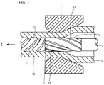
- FIG. 1 is a schematic diagram of a cold drawing step of the present embodiment.
- a cold drawing apparatus includes a die 1, a plug 2, and a mandrel 3.
- the die 1 includes, in the order from an entrance side (right side in FIG. 1 ) toward an exit side (left side in FIG. 1 ), an approach part, a bearing part, and a relief part, successively.
- the approach part has a so-called taper shape in which the inner diameter gradually decreases from the entrance side toward the exit side of the die 1.
- the shape of the approach part is not limited to the tapered type, and other shapes such as an R-type having a curvature will not be precluded.
- the bearing part is made up of a cylinder, whose inner diameter is constant and corresponds to the die diameter. In the relief part, the inner diameter gradually increases from the entrance side toward the exit side.
- the die 1 is fixed, for example, to a draw bench not shown.
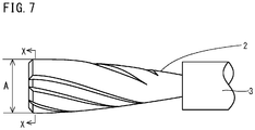
- the plug 2 has a columnar shape.
- the plug 2 includes a plurality of helical grooves 21 and a plurality of second helical ribs 22 on its surface.
- the second helical rib 22 is located between adjacent helical grooves 21.
- the plurality of helical grooves 21 and the second helical ribs 22 extend in a helical fashion along the central axis of the plug 2.
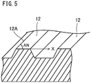
- the plurality of helical grooves 21 and the second helical ribs 22 form a plurality of first helical ribs 12 on the inner surface 11 of the rifled tube 15.
- the first helical rib 12 extends in a helical fashion along the central axis of the rifled tube 15.
- the inner surface 11 constitutes helical grooves.
- the first helical rib 12 and the helical groove (inner surface) 11 are alternately arranged.
- a front end of the plug 2 is attached to a rear end of the mandrel 3.
- the plug 2 is attached to the mandrel 3 so as to be rotatable around the central axis of the plug 2.
- the plug 2 forms first helical ribs 12 on the inner surface of the steel tube 10 while the plug 2 rotates.
- the mandrel 3 supports the plug 2 during cold drawing, and holds the plug 2 in a predetermined position.
- the plug 2 further satisfies Formulae (1) and (2): 0.08 ⁇ W ⁇ A ⁇ B ⁇ N / 2 ⁇ ⁇ A ⁇ 0.26 0.83 ⁇ S ⁇ A ⁇ B ⁇ N / 2 ⁇ M ⁇ 2.0 where, in Formulae (1) and (2), W is substituted by a width (mm) of a groove bottom surface of the helical groove 21 in a cross section perpendicular to a central axis of the plug 2. A is substituted by a maximum diameter (mm) of the plug 2, and B is substituted by a minimum diameter (mm) of the plug 2 in the same cross section as that of the maximum diameter A. N is substituted by a number of the second helical ribs 22 in the above described cross section.
- S is substituted by the width (mm) of the groove bottom surface of the helical groove 21 in a longitudinal section parallel with the central axis of the plug 2.
- M is substituted by a pitch (mm) of adjacent second helical ribs 22 in the above described longitudinal section.
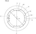
- Formula (1) shows the relationship between the second helical rib 22 and helical groove 21 in a cross section of the plug 2.
- FIG. 2 is a sectional (cross-sectional) view perpendicular to the central axis of the plug 2 in FIG. 1 .
- a maximum circle indicated by a broken line in FIG. 2 is an outer peripheral surface of a rifle tube 15.
- the plug 2 includes the helical groove 21 and the second helical rib 22. In a portion corresponding to the helical groove 21, the first helical rib 12 of the rifle tube 15 is formed.
- W is the width (mm) of the groove bottom surface 210 of the helical groove 21 in a cross section.
- the width W is represented by the distance (mm) along a circle 21C of a minimum diameter B of the plug 2 in the cross section.
- the width W is defined by the distance (mm) between two intersection points 21P at which the edge part of the radius of curvature 21R intersects with the circle 21C.
- a maximum diameter A is a straight line distance from the top of a second helical rib 22 up to the top of the second helical rib 22 on the opposite side through the central axis CL of the plug 2.
- a minimum diameter B is a straight line distance from the groove bottom surface 210 of a helical groove 21 up to the groove bottom surface 210 on the opposite side through the central axis CL in the same cross section as that of the maximum diameter A.
- N is the number of the helical ribs 22 in the cross-section shown in FIG. 2 . In FIG. 2 , N is 4. However, the number of the second helical ribs 22 is not particularly limited as long as it is plural. The number N of the second helical ribs 22 may be 2 or may be 6. The number of the second helical ribs 22 may be an odd number.
- a load exerted on the plug 2 during cold drawing is dependent on the degree of unevenness in the outer peripheral surface of the plug 2, that is, dependent on the shapes of the helical groove 21 and the second helical rib 22.
- F1 W x (A - B) x N/(2 ⁇ x A).
- F1 indicates a proportion occupied by the helical groove 21 in the outer peripheral surface of the plug 2.
- F1 is not less than 0.26, the load exerted on the plug 2 becomes excessively high and seizure is likely to occur in the plug 2.
- F1 is less than 0.26, it is possible to suppress the load exerted on the plug 2 on condition that Formula (2) is satisfied. Therefore, in the cold drawing, seizure is unlikely to occur in the plug 2.
- An upper limit of F1 is preferably 0.22, and more preferably 0.18.
- F1 is greater than 0.08.
- a lower limit of F1 is preferably 0.10, and more preferably 0.12.
- Formula (2) shows the relationship between the second helical rib 22 and helical groove 21 in a longitudinal section of the plug 2.
- FIG. 4 shows a part of a section parallel with the central axis (longitudinal section) of the plug 2 in FIG. 1 .
- a width S of the helical groove 21 in a longitudinal section is represented by a distance (a straight-line distance in this case, in the unit of mm) along the outer peripheral surface (a straight line in this case) of a minimum diameter B of the plug 2.
- M is a pitch (mm) of the second helical rib 22, and specifically is the distance between adjacent second helical ribs 22 in a longitudinal section.
- the distance between the center of a second helical rib 22 and the center of an adjacent second helical rib 22 is defined as a pitch (mm).
- a load exerted on the plug 2 during cold drawing is, as described above, dependent on the degree of unevenness of the outer peripheral surface of the plug 2. Not only the cross sectional shape of the plug 2, but also the longitudinal sectional shape affects the degree of unevenness of the outer peripheral surface of the plug 2.
- F2 S x (A - B) x N/(2 x M).
- F2 indicates a proportion occupied by the helical groove 21 in the outer peripheral surface of the plug 2.
- F2 is not less than 2.0, the load exerted on the plug 2 becomes excessively high, and seizure is likely to occur in the plug 2.
- F2 is less than 2.0, it is possible to suppress the load exerted on the plug 2 on condition that Formula (1) is satisfied. As a result of that, seizure is unlikely to occur in the plug 2 in cold drawing.
- An upper limit of F2 is preferably 1.8.
- F2 is not more than 0.83
- the rifle tube 15 will not function as a rifle tube since the area of the longitudinal sectional shape of the first helical rib 12 of the rifle tube 15 is too small. Accordingly, a lower limit of F2 is more than 0.83.
- the lower limit of F2 is more preferably 0.90.
- the cold drawing step using a plug 2 of the above described shape is performed, for example, as follows. First, a front end part of the steel tube 10 is subjected to nosing. Next, the front end part of the processed steel tube 10 is inserted into the die 1. After insertion, the steel tube 10 is fixed. For example, the front end part of the steel tube 10 is gripped by a chuck of a drawbench (not shown). Thus, the steel tube 10 is fixed.
- the plug 2 is rotatably attached to the nose of the mandrel 3. After attachment, the plug 2 is inserted into the steel tube 10 from the rear end side of the steel tube 10 (entrance side of the die 1) in the drawing direction Z (see FIG. 1 ).
- the steel tube 10 which is fixed by the chuck or the like, is drawn in the drawing direction Z.
- the plug 2 is advanced in the drawing direction Z so that the plug 2 is held at a position where the portion having the maximum diameter A of the plug 2 is closer to the exit side than to the approach part of the die 1.
- the steel tube 10 is further drawn to produce a rifled tube 15.
- the plug 2 is driven to move (automatically rotate) in association therewith.
- a plurality of first helical ribs 12 are formed in the inner surface 11 of the steel tube 10.
- the production method described above is particularly suitable for the preparation of a rifled tube 15 having an outer diameter of not more than 34 mm.
- the diameter of the plug 2 to be used also becomes large.
- the diameter of the plug 2 is large, the area ratio of the helical groove 21 with respect to the diameter of the plug 2 naturally becomes small. In this case, the uneven shape of the outer peripheral surface of the plug 2 when subjected to the cold drawing does not significantly have an effect on seizure of the plug 2.
- the outside diameter of the rifled tube 15 is small, the diameter of the plug 2 becomes also small.
- the area ratio of the helical groove 21 with respect to the diameter of the plug 2 increases, and the shapes of the helical groove 21 and the second helical rib 22 have an effect on seizure of the plug 2 during cold drawing. According to the production method of the present embodiment, it is possible to suppress occurrence of seizure even when a rifled tube 15 having an outer diameter of not more than 34 mm is produced.
- the lead angle (deg) is defined as an angle AN formed between the tube axis direction X of the rifled tube 15 and a side edge 12A of the upper surface of the first helical rib 12.
- the lead angle is preferably 30 to 43 deg.
- the rifled tube 15 can further suppress occurrence of film boiling.
- the above described preparation step includes a softening heat treatment step.
- the softening heat treatment step before the cold drawing step is carried out, the blank tube is softened by heat treatment to form a steel tube. This will improve workability of the steel tube in the cold drawing step.
- a one-stage heat treatment is performed.
- the one-stage heat treatment is as follows.
- the blank tube is charged into a heat treatment furnace.
- the blank tube is soaked at a heat treatment temperature from less than Ac 1 point to Ac 1 point - 100°C.
- the soaking time is preferably 30 to 60 minutes.
- a two-stage heat treatment in place of the one-stage heat treatment, is performed.
- the two-stage heat treatment includes a first heat treatment step and a second heat treatment step.
- the first heat treatment step first, the blank tube is charged into a heat treatment furnace and is soaked at a first heat treatment temperature, which is a y range temperature of Ac 3 point to Ac 3 point + 50°C (the first heat treatment step). Subsequently, the heat treatment temperature is lowered to a second heat treatment temperature of less than Ar 1 point to Ar 1 point - 100°C, and the blank tube is soaked at the second heat treatment temperature (the second heat treatment step).
- the microstructure of the blank tube becomes an austenite single phase.
- the soaking time in the first heat treatment step is preferably 5 minutes to 10 minutes.
- the soaking time in the second heat treatment step is preferably 30 minutes to 60 minutes.
- the first heat treatment step and the second heat treatment step may be performed in the same heat treatment furnace, or may be performed in different heat treatment furnaces.
- cold drawing for forming the steel tube having a circular cross section may be performed by using a plug having a smooth surface for the purpose of increasing the roundness of the steel tube.
- a lubricating treatment such as a chemical treatment is performed on the inner and outer surfaces of the steel tube.
- Oxide scale of the inner and outer surfaces of the steel tube may be removed by a descaling treatment after the heat treatment step and before carrying out the cold drawing step.
- the chemical treatment is performed after the descaling treatment.
- the plug 2 has a columnar shape.
- the shape of the plug 2 is not limited to a column.
- the plug 2 may be bullet-shaped as shown in FIG. 6 .
- the maximum diameter A is positioned at the rear end of the plug 2.
- the minimum diameter B is supposed to be the minimum diameter in the cross section X where the maximum diameter A is obtained.
- a plurality of rifled tubes having ribs of different shapes were produced to investigate occurrence or nonoccurrence of seizure in cold drawing.
- Plugs used in Test Nos. 1 to 10 each had a shape different from each other. F1 and F2 of each plug were as shown in Table 1.
- Each steel tube of each test number which was prepared by cold drawing, had a chemical composition corresponding to STBA22 defined in JIS G3462 (2009) and contained 1.25 mass% of Cr.
- the Ac 1 point of these steel tubes was 742°C.
- Each steel tube was produced by the following method. A billet having the chemical composition described above was prepared. By using the billet, a blank tube was produced by the Mannesmann-mandrel process. In order to improve the roundness, cold drawing process was performed on the blank tube by using a plug having smooth surface to produce a steel tube (seamless steel tube).
- the one-stage heat treatment described above was performed on each steel tube.
- the heat treatment temperature was 740°C and the soaking time was 20 minutes.
- Tensile test specimens were taken from steel tubes after heat treatment, and were subjected to a tensile test at room temperature (25°C) to obtain tensile strengths TS (MPa).
- the resultant tensile strengths TS were 462 MPa to 497 MPa.
- the steel tubes after heat treatment were subjected to cold drawing by use of zinc phosphate based lubricant and plugs having F1 and F2 shown in Table 1 to produce rifled tubes.
- the outer diameters (mm) and thicknesses (mm) of the rifled tubes were as shown in Table 1.
- FIG. 8 is a diagram showing relationship between F1 and F2, and occurrence or nonoccurrence of seizure.
- An open circle ( ⁇ ) in FIG. 8 means that no seizure occurred, and a solid circle ( ⁇ ) means that seizure occurred.
- the numbers denoted next to the open circle and the solid circle refer to Test Nos.
- F1 and F2 of the plug used satisfied Formulae (1) and (2). Therefore, even when rifled tubes having an outer diameter of as small as not more than 34 mm were produced, the maximum loads during cold drawing were less than 3.5 ton, and no seizing was observed.
- a plurality of steel tubes having a chemical composition corresponding to STBA24 defined in JIS G3462 (2009) and containing 2.25 mass% of Cr were prepared.
- the Ar 1 point of these steel tubes was 773°C and the Ac 3 point was 881°C.
- steel tubes were produced by the following method. Using a billet having the above described chemical composition, blank tubes were produced by the Mannesmann-mandrel process. In order to increase the roundness, blank tubes were subjected to cold drawing using a plug having smooth surface. After the steps described above, steel tubes (seamless steel tubes) of each Test No. were prepared.
- Test No. 11-1 A two-stage heat treatment was performed on Test No. 11-1 and a one-stage heat treatment was performed on Test No. 11-2.
- the steel tube of Test No. 11-1 was subjected to a two-stage heat treatment in which the heat treatment temperature in the first heat treatment step was 920°C, and the soaking time was 10 minutes.
- the heat treatment temperature in the second heat treatment step was 725°C, and the soaking time was 45 minutes.
- the steel tube of Test No. 11-2 was subjected to a one-step heat treatment, in which the heat treatment temperature was 760°C, and the soaking time was 20 minutes.
- a tensile test specimen was taken from each steel tube after heat treatment. Using the tensile test specimen, a tensile test was performed at room temperature (25°C) to obtain a tensile strength TS (MPa). The resulting tensile strengths TS were 460 MPa for Test No. 11, and 530 MPa for Test No. 12.
- the steel tubes of Test Nos. 11-1 and 11-2 were subjected to cold drawing by using the plugs of F1 and F2 shown in Table 2 to produce rifled tubes.
- the helical groove of the plug was set such that the lead angle of the rifled tube would be 40 deg.
- the load exerted on the mandrel during cold drawing was measured to obtain the maximum load thereof.
- the outer diameter of the rifled tube of each Test No. produced was 31.8 mm, and the thickness thereof was 5.6 mm.
- the surface of the plug used was visually observed to confirm the occurrence or nonoccurrence of seizure. Furthermore, the lead angle of each rifled tube produced was measured. Then, an error of the measured lead angle from 40 deg was calculated. When the error was -0 to +3 deg, it was evaluated as that the lead angle was highly accurate.
- Test results are shown in Table 2.
- the "lead angle evaluation” column shows the results of measurement of lead angle.
- E Excellent
- G Good
- the error was -0 deg to -1 deg (excluding -0 deg), or more than +3 deg to +5 deg.
- Test No. 11-1 As a result of performing the two-stage heat treatment, the tensile strength TS before cold drawing was lower than that of Test No. 11-2 as was not more than 500 MPa. Therefore, Test No. 11-1, compared with Test No. 11-2, had a lower maximum load, and the accuracy of the lead angle was as high as within -0 to +3 deg.
Applications Claiming Priority (2)
| Application Number | Priority Date | Filing Date | Title |
|---|---|---|---|
| JP2014238171 | 2014-11-25 | ||
| PCT/JP2015/005823 WO2016084361A1 (ja) | 2014-11-25 | 2015-11-24 | ライフルチューブの製造方法 |
Publications (4)
| Publication Number | Publication Date |
|---|---|
| EP3225319A1 true EP3225319A1 (de) | 2017-10-04 |
| EP3225319A4 EP3225319A4 (de) | 2018-08-08 |
| EP3225319B1 EP3225319B1 (de) | 2020-11-11 |
| EP3225319B8 EP3225319B8 (de) | 2021-01-06 |
Family
ID=56073950
Family Applications (1)
| Application Number | Title | Priority Date | Filing Date |
|---|---|---|---|
| EP15863144.0A Active EP3225319B8 (de) | 2014-11-25 | 2015-11-24 | Verfahren zur herstellung eines drallrohrs |
Country Status (14)
| Country | Link |
|---|---|
| US (1) | US10632521B2 (de) |
| EP (1) | EP3225319B8 (de) |
| JP (1) | JP6431548B2 (de) |
| KR (1) | KR101950628B1 (de) |
| CN (1) | CN107000009B (de) |
| BR (1) | BR112017010752B1 (de) |
| CL (1) | CL2017001325A1 (de) |
| ES (1) | ES2844405T3 (de) |
| MX (1) | MX2017006955A (de) |
| MY (1) | MY188610A (de) |
| PH (1) | PH12017500950A1 (de) |
| RU (1) | RU2664494C1 (de) |
| TW (1) | TWI566850B (de) |
| WO (1) | WO2016084361A1 (de) |
Families Citing this family (6)
| Publication number | Priority date | Publication date | Assignee | Title |
|---|---|---|---|---|
| CN106755785B (zh) * | 2016-11-22 | 2018-09-14 | 沈阳黎明航空发动机(集团)有限责任公司 | 一种防止管接头零件淬火变形的方法 |
| KR20200090518A (ko) | 2019-01-21 | 2020-07-29 | 부산대학교 산학협력단 | 비구동 회전형 인발 다이를 이용한 헬리컬 바의 제조장치 |
| CN109967988B (zh) * | 2019-03-18 | 2020-10-27 | 青岛登辉机械配件有限公司 | 内螺纹外翅管加工工艺 |
| CN111842517A (zh) * | 2020-07-24 | 2020-10-30 | 浙江久立特材科技股份有限公司 | 一种带肋包壳管的冷拔模具、生产工艺及其成品管 |
| RU203923U1 (ru) * | 2020-12-28 | 2021-04-28 | федеральное государственное бюджетное образовательное учреждение высшего образования «Белгородский государственный технологический университет им. В.Г. Шухова» | Продольный канал секции отопительного прибора |
| CN113070375B (zh) * | 2021-03-25 | 2022-11-15 | 江西耐乐铜业有限公司 | 一种铜管内螺纹成型调节系统 |
Family Cites Families (18)
| Publication number | Priority date | Publication date | Assignee | Title |
|---|---|---|---|---|
| US3830087A (en) | 1970-07-01 | 1974-08-20 | Sumitomo Metal Ind | Method of making a cross-rifled vapor generating tube |
| JPS5645208A (en) * | 1979-04-27 | 1981-04-24 | Sumitomo Metal Ind Ltd | Drawing method for internally rifled pipe and plug for use of present method |
| SU1082504A1 (ru) * | 1983-04-08 | 1984-03-30 | Магнитогорский горно-металлургический институт им.Г.И.Носова | Оправка дл производства изделий с внутренними спиральными ребрами |
| EP0153970A1 (de) * | 1984-03-07 | 1985-09-11 | Wieland-Werke AG | Verfahren und Vorrichtung zur Herstellung eines Rohres mit schraubenlinienförmig verlaufenden Innenrippen |
| JPH0231205Y2 (de) * | 1984-10-18 | 1990-08-23 | ||
| US4799972A (en) * | 1985-10-14 | 1989-01-24 | Sumitomo Metal Industries, Ltd. | Process for producing a high strength high-Cr ferritic heat-resistant steel |
| US4854148A (en) * | 1987-06-19 | 1989-08-08 | The Babcock & Wilcox Company | Cold drawing technique and apparatus for forming internally grooved tubes |
| SU1650294A1 (ru) * | 1987-12-29 | 1991-05-23 | Магнитогорский горно-металлургический институт им.Г.И.Носова | Оправка дл получени полых изделий с внутренними встречно направленными ребрами |
| JPH0621323B2 (ja) * | 1989-03-06 | 1994-03-23 | 住友金属工業株式会社 | 耐食、耐酸化性に優れた高強度高クロム鋼 |
| JPH04224013A (ja) * | 1990-12-21 | 1992-08-13 | Nkk Corp | 鋼管のライフル伸管方法 |
| JP2004298899A (ja) * | 2003-03-28 | 2004-10-28 | Kobe Steel Ltd | 内面溝付管の製造装置及び製造方法 |
| JP2005221153A (ja) * | 2004-02-05 | 2005-08-18 | Sumitomo Metal Ind Ltd | 熱分解反応用鋼管 |
| US7021106B2 (en) * | 2004-04-15 | 2006-04-04 | Mitsui Babcock (Us) Llc | Apparatus and method for forming internally ribbed or rifled tubes |
| JP4577611B2 (ja) | 2005-03-29 | 2010-11-10 | 住友金属工業株式会社 | ライフルチューブ引抜加工用工具及びこれを用いたライフルチューブの製造方法 |
| US7934332B2 (en) | 2006-02-23 | 2011-05-03 | Sturm, Ruger & Company, Inc. | Composite firearm barrel |
| EP2228149B1 (de) * | 2007-12-26 | 2017-02-01 | Nippon Steel & Sumitomo Metal Corporation | Herstellungsverfahren für innen geripptes stahlrohr |
| WO2009081670A1 (ja) * | 2007-12-26 | 2009-07-02 | Sumitomo Metal Industries, Ltd. | 被覆超硬プラグおよびそれを用いた冷間引抜方法 |
| AU2013266864B2 (en) * | 2012-05-24 | 2017-04-06 | Deka Products Limited Partnership | Apparatus for infusing fluid |
-
2015
- 2015-11-24 RU RU2017122143A patent/RU2664494C1/ru active
- 2015-11-24 TW TW104138964A patent/TWI566850B/zh active
- 2015-11-24 CN CN201580064270.1A patent/CN107000009B/zh active Active
- 2015-11-24 BR BR112017010752-0A patent/BR112017010752B1/pt active IP Right Grant
- 2015-11-24 EP EP15863144.0A patent/EP3225319B8/de active Active
- 2015-11-24 US US15/528,774 patent/US10632521B2/en active Active
- 2015-11-24 ES ES15863144T patent/ES2844405T3/es active Active
- 2015-11-24 KR KR1020177017371A patent/KR101950628B1/ko active IP Right Grant
- 2015-11-24 JP JP2016561241A patent/JP6431548B2/ja active Active
- 2015-11-24 WO PCT/JP2015/005823 patent/WO2016084361A1/ja active Application Filing
- 2015-11-24 MY MYPI2017701889A patent/MY188610A/en unknown
- 2015-11-24 MX MX2017006955A patent/MX2017006955A/es unknown
-
2017
- 2017-05-24 PH PH12017500950A patent/PH12017500950A1/en unknown
- 2017-05-24 CL CL2017001325A patent/CL2017001325A1/es unknown
Also Published As
| Publication number | Publication date |
|---|---|
| EP3225319B8 (de) | 2021-01-06 |
| BR112017010752B1 (pt) | 2021-10-26 |
| PH12017500950A1 (en) | 2017-10-02 |
| CN107000009A (zh) | 2017-08-01 |
| TWI566850B (zh) | 2017-01-21 |
| TW201632277A (zh) | 2016-09-16 |
| MY188610A (en) | 2021-12-22 |
| CL2017001325A1 (es) | 2017-12-11 |
| JP6431548B2 (ja) | 2018-11-28 |
| JPWO2016084361A1 (ja) | 2017-11-02 |
| EP3225319B1 (de) | 2020-11-11 |
| KR101950628B1 (ko) | 2019-02-20 |
| MX2017006955A (es) | 2017-08-10 |
| RU2664494C1 (ru) | 2018-08-17 |
| KR20170087940A (ko) | 2017-07-31 |
| ES2844405T3 (es) | 2021-07-22 |
| EP3225319A4 (de) | 2018-08-08 |
| CN107000009B (zh) | 2019-01-01 |
| WO2016084361A1 (ja) | 2016-06-02 |
| US10632521B2 (en) | 2020-04-28 |
| US20170320124A1 (en) | 2017-11-09 |
| BR112017010752A2 (pt) | 2018-01-09 |
Similar Documents
| Publication | Publication Date | Title |
|---|---|---|
| EP3225319B1 (de) | Verfahren zur herstellung eines drallrohrs | |
| JP5273036B2 (ja) | 一体成形型ドライブシャフト用冷間仕上継目無鋼管およびそれを用いたドライブシャフト、並びにその冷間仕上継目無鋼管の製造方法 | |
| CN110052792B (zh) | 一种液压缸用缸筒的制造方法 | |
| JPWO2005075121A1 (ja) | 冷間仕上げ継目無鋼管 | |
| CN103084426A (zh) | 一种核聚变反应堆用不锈钢异形管的制造方法 | |
| WO2013179496A1 (ja) | 金属管の拡管製造方法 | |
| CN109477173A (zh) | 耐应力腐蚀裂纹性优异的锅炉用电阻焊钢管及其制造方法 | |
| JP2008173643A (ja) | 二相ステンレス鋼管の製造方法、矯正方法および強度調整方法、ならびに、二相ステンレス鋼管の矯正機の操業方法 | |
| CN110538890B (zh) | 一种uns s32906无缝管的制造方法 | |
| CN110306120A (zh) | 一种X80钢级D1422mm无缝弯管及其制造方法 | |
| JP6686803B2 (ja) | 口絞り方法及び二相ステンレス鋼管の製造方法 | |
| JP5716468B2 (ja) | 継目無管の冷間圧延方法 | |
| JP6737321B2 (ja) | 継目無鋼管の製造方法 | |
| JPH1157842A (ja) | 管軸長方向の圧縮強度に優れた鋼管の製造方法 | |
| CN104388653A (zh) | 一种热轧12Cr1MoV无缝钢管后处理工艺及其所得钢管 | |
| JP6378141B2 (ja) | フレア加工用銅又は銅合金管 | |
| EP4094856A1 (de) | Nahtloses rohr und verfahren zum herstellen desselben | |
| JP7265131B2 (ja) | 金属管及び金属管の製造方法 | |
| KR101577160B1 (ko) | 이음매 없는 관의 냉간 압연 방법 | |
| JP2023134349A (ja) | 金属管の圧延方法、金属管の製造方法、圧延設備及び金属管 | |
| JPH1080715A (ja) | 冷間加工のままで使用される鋼管の製造方法 | |
| RU2378067C1 (ru) | Способ изготовления тонкостенных труб | |
| CN109536829A (zh) | 一种汽车半轴套用无缝钢管及其生产方法 | |
| WO2012070237A1 (ja) | 鋼管の冷間引抜き方法 |
Legal Events
| Date | Code | Title | Description |
|---|---|---|---|
| STAA | Information on the status of an ep patent application or granted ep patent |
Free format text: STATUS: THE INTERNATIONAL PUBLICATION HAS BEEN MADE |
|
| PUAI | Public reference made under article 153(3) epc to a published international application that has entered the european phase |
Free format text: ORIGINAL CODE: 0009012 |
|
| STAA | Information on the status of an ep patent application or granted ep patent |
Free format text: STATUS: REQUEST FOR EXAMINATION WAS MADE |
|
| 17P | Request for examination filed |
Effective date: 20170622 |
|
| AK | Designated contracting states |
Kind code of ref document: A1 Designated state(s): AL AT BE BG CH CY CZ DE DK EE ES FI FR GB GR HR HU IE IS IT LI LT LU LV MC MK MT NL NO PL PT RO RS SE SI SK SM TR |
|
| AX | Request for extension of the european patent |
Extension state: BA ME |
|
| DAV | Request for validation of the european patent (deleted) | ||
| DAX | Request for extension of the european patent (deleted) | ||
| A4 | Supplementary search report drawn up and despatched |
Effective date: 20180711 |
|
| RIC1 | Information provided on ipc code assigned before grant |
Ipc: B21C 3/16 20060101ALI20180705BHEP Ipc: B21C 1/24 20060101ALI20180705BHEP Ipc: B21C 37/20 20060101AFI20180705BHEP |
|
| RAP1 | Party data changed (applicant data changed or rights of an application transferred) |
Owner name: MITSUBISHI HITACHI POWER SYSTEMS, LTD. Owner name: NIPPON STEEL CORPORATION |
|
| STAA | Information on the status of an ep patent application or granted ep patent |
Free format text: STATUS: EXAMINATION IS IN PROGRESS |
|
| 17Q | First examination report despatched |
Effective date: 20191008 |
|
| GRAP | Despatch of communication of intention to grant a patent |
Free format text: ORIGINAL CODE: EPIDOSNIGR1 |
|
| STAA | Information on the status of an ep patent application or granted ep patent |
Free format text: STATUS: GRANT OF PATENT IS INTENDED |
|
| INTG | Intention to grant announced |
Effective date: 20200629 |
|
| GRAS | Grant fee paid |
Free format text: ORIGINAL CODE: EPIDOSNIGR3 |
|
| GRAA | (expected) grant |
Free format text: ORIGINAL CODE: 0009210 |
|
| STAA | Information on the status of an ep patent application or granted ep patent |
Free format text: STATUS: THE PATENT HAS BEEN GRANTED |
|
| AK | Designated contracting states |
Kind code of ref document: B1 Designated state(s): AL AT BE BG CH CY CZ DE DK EE ES FI FR GB GR HR HU IE IS IT LI LT LU LV MC MK MT NL NO PL PT RO RS SE SI SK SM TR |
|
| REG | Reference to a national code |
Ref country code: GB Ref legal event code: FG4D |
|
| REG | Reference to a national code |
Ref country code: CH Ref legal event code: EP |
|
| REG | Reference to a national code |
Ref country code: AT Ref legal event code: REF Ref document number: 1332957 Country of ref document: AT Kind code of ref document: T Effective date: 20201115 |
|
| REG | Reference to a national code |
Ref country code: DE Ref legal event code: R082 Ref document number: 602015061989 Country of ref document: DE Representative=s name: ZIMMERMANN & PARTNER PATENTANWAELTE MBB, DE Ref country code: DE Ref legal event code: R081 Ref document number: 602015061989 Country of ref document: DE Owner name: NIPPON STEEL CORPORATION, JP Free format text: FORMER OWNERS: MITSUBISHI HITACHI POWER SYSTEMS, LTD., YOKOHAMA-SHI, KANAGAWA, JP; NIPPON STEEL CORPORATION, TOKYO, JP Ref country code: DE Ref legal event code: R081 Ref document number: 602015061989 Country of ref document: DE Owner name: MITSUBISHI POWER, LTD., YOKOHAMA-SHI, JP Free format text: FORMER OWNERS: MITSUBISHI HITACHI POWER SYSTEMS, LTD., YOKOHAMA-SHI, KANAGAWA, JP; NIPPON STEEL CORPORATION, TOKYO, JP |
|
| REG | Reference to a national code |
Ref country code: DE Ref legal event code: R096 Ref document number: 602015061989 Country of ref document: DE |
|
| RAP2 | Party data changed (patent owner data changed or rights of a patent transferred) |
Owner name: MITSUBISHI POWER, LTD. Owner name: NIPPON STEEL CORPORATION |
|
| REG | Reference to a national code |
Ref country code: IE Ref legal event code: FG4D |
|
| REG | Reference to a national code |
Ref country code: CH Ref legal event code: PK Free format text: BERICHTIGUNG B8 |
|
| REG | Reference to a national code |
Ref country code: SK Ref legal event code: T3 Ref document number: E 35973 Country of ref document: SK |
|
| REG | Reference to a national code |
Ref country code: NL Ref legal event code: MP Effective date: 20201111 |
|
| REG | Reference to a national code |
Ref country code: AT Ref legal event code: MK05 Ref document number: 1332957 Country of ref document: AT Kind code of ref document: T Effective date: 20201111 |
|
| PG25 | Lapsed in a contracting state [announced via postgrant information from national office to epo] |
Ref country code: GR Free format text: LAPSE BECAUSE OF FAILURE TO SUBMIT A TRANSLATION OF THE DESCRIPTION OR TO PAY THE FEE WITHIN THE PRESCRIBED TIME-LIMIT Effective date: 20210212 Ref country code: PT Free format text: LAPSE BECAUSE OF FAILURE TO SUBMIT A TRANSLATION OF THE DESCRIPTION OR TO PAY THE FEE WITHIN THE PRESCRIBED TIME-LIMIT Effective date: 20210311 Ref country code: RS Free format text: LAPSE BECAUSE OF FAILURE TO SUBMIT A TRANSLATION OF THE DESCRIPTION OR TO PAY THE FEE WITHIN THE PRESCRIBED TIME-LIMIT Effective date: 20201111 Ref country code: FI Free format text: LAPSE BECAUSE OF FAILURE TO SUBMIT A TRANSLATION OF THE DESCRIPTION OR TO PAY THE FEE WITHIN THE PRESCRIBED TIME-LIMIT Effective date: 20201111 Ref country code: NO Free format text: LAPSE BECAUSE OF FAILURE TO SUBMIT A TRANSLATION OF THE DESCRIPTION OR TO PAY THE FEE WITHIN THE PRESCRIBED TIME-LIMIT Effective date: 20210211 |
|
| PG25 | Lapsed in a contracting state [announced via postgrant information from national office to epo] |
Ref country code: SE Free format text: LAPSE BECAUSE OF FAILURE TO SUBMIT A TRANSLATION OF THE DESCRIPTION OR TO PAY THE FEE WITHIN THE PRESCRIBED TIME-LIMIT Effective date: 20201111 Ref country code: IS Free format text: LAPSE BECAUSE OF FAILURE TO SUBMIT A TRANSLATION OF THE DESCRIPTION OR TO PAY THE FEE WITHIN THE PRESCRIBED TIME-LIMIT Effective date: 20210311 Ref country code: PL Free format text: LAPSE BECAUSE OF FAILURE TO SUBMIT A TRANSLATION OF THE DESCRIPTION OR TO PAY THE FEE WITHIN THE PRESCRIBED TIME-LIMIT Effective date: 20201111 Ref country code: LV Free format text: LAPSE BECAUSE OF FAILURE TO SUBMIT A TRANSLATION OF THE DESCRIPTION OR TO PAY THE FEE WITHIN THE PRESCRIBED TIME-LIMIT Effective date: 20201111 Ref country code: BG Free format text: LAPSE BECAUSE OF FAILURE TO SUBMIT A TRANSLATION OF THE DESCRIPTION OR TO PAY THE FEE WITHIN THE PRESCRIBED TIME-LIMIT Effective date: 20210211 Ref country code: AT Free format text: LAPSE BECAUSE OF FAILURE TO SUBMIT A TRANSLATION OF THE DESCRIPTION OR TO PAY THE FEE WITHIN THE PRESCRIBED TIME-LIMIT Effective date: 20201111 |
|
| REG | Reference to a national code |
Ref country code: SK Ref legal event code: T4 Ref document number: E 35973 Country of ref document: SK |
|
| REG | Reference to a national code |
Ref country code: LT Ref legal event code: MG9D |
|
| PG25 | Lapsed in a contracting state [announced via postgrant information from national office to epo] |
Ref country code: HR Free format text: LAPSE BECAUSE OF FAILURE TO SUBMIT A TRANSLATION OF THE DESCRIPTION OR TO PAY THE FEE WITHIN THE PRESCRIBED TIME-LIMIT Effective date: 20201111 |
|
| REG | Reference to a national code |
Ref country code: CH Ref legal event code: PL |
|
| REG | Reference to a national code |
Ref country code: ES Ref legal event code: FG2A Ref document number: 2844405 Country of ref document: ES Kind code of ref document: T3 Effective date: 20210722 |
|
| PG25 | Lapsed in a contracting state [announced via postgrant information from national office to epo] |
Ref country code: RO Free format text: LAPSE BECAUSE OF FAILURE TO SUBMIT A TRANSLATION OF THE DESCRIPTION OR TO PAY THE FEE WITHIN THE PRESCRIBED TIME-LIMIT Effective date: 20201111 Ref country code: SM Free format text: LAPSE BECAUSE OF FAILURE TO SUBMIT A TRANSLATION OF THE DESCRIPTION OR TO PAY THE FEE WITHIN THE PRESCRIBED TIME-LIMIT Effective date: 20201111 Ref country code: LT Free format text: LAPSE BECAUSE OF FAILURE TO SUBMIT A TRANSLATION OF THE DESCRIPTION OR TO PAY THE FEE WITHIN THE PRESCRIBED TIME-LIMIT Effective date: 20201111 Ref country code: LU Free format text: LAPSE BECAUSE OF NON-PAYMENT OF DUE FEES Effective date: 20201124 Ref country code: EE Free format text: LAPSE BECAUSE OF FAILURE TO SUBMIT A TRANSLATION OF THE DESCRIPTION OR TO PAY THE FEE WITHIN THE PRESCRIBED TIME-LIMIT Effective date: 20201111 Ref country code: CZ Free format text: LAPSE BECAUSE OF FAILURE TO SUBMIT A TRANSLATION OF THE DESCRIPTION OR TO PAY THE FEE WITHIN THE PRESCRIBED TIME-LIMIT Effective date: 20201111 |
|
| REG | Reference to a national code |
Ref country code: BE Ref legal event code: MM Effective date: 20201130 |
|
| REG | Reference to a national code |
Ref country code: DE Ref legal event code: R097 Ref document number: 602015061989 Country of ref document: DE |
|
| PG25 | Lapsed in a contracting state [announced via postgrant information from national office to epo] |
Ref country code: LI Free format text: LAPSE BECAUSE OF NON-PAYMENT OF DUE FEES Effective date: 20201130 Ref country code: MC Free format text: LAPSE BECAUSE OF FAILURE TO SUBMIT A TRANSLATION OF THE DESCRIPTION OR TO PAY THE FEE WITHIN THE PRESCRIBED TIME-LIMIT Effective date: 20201111 Ref country code: DK Free format text: LAPSE BECAUSE OF FAILURE TO SUBMIT A TRANSLATION OF THE DESCRIPTION OR TO PAY THE FEE WITHIN THE PRESCRIBED TIME-LIMIT Effective date: 20201111 Ref country code: CH Free format text: LAPSE BECAUSE OF NON-PAYMENT OF DUE FEES Effective date: 20201130 |
|
| PLBE | No opposition filed within time limit |
Free format text: ORIGINAL CODE: 0009261 |
|
| STAA | Information on the status of an ep patent application or granted ep patent |
Free format text: STATUS: NO OPPOSITION FILED WITHIN TIME LIMIT |
|
| 26N | No opposition filed |
Effective date: 20210812 |
|
| GBPC | Gb: european patent ceased through non-payment of renewal fee |
Effective date: 20210211 |
|
| PG25 | Lapsed in a contracting state [announced via postgrant information from national office to epo] |
Ref country code: NL Free format text: LAPSE BECAUSE OF FAILURE TO SUBMIT A TRANSLATION OF THE DESCRIPTION OR TO PAY THE FEE WITHIN THE PRESCRIBED TIME-LIMIT Effective date: 20201111 Ref country code: AL Free format text: LAPSE BECAUSE OF FAILURE TO SUBMIT A TRANSLATION OF THE DESCRIPTION OR TO PAY THE FEE WITHIN THE PRESCRIBED TIME-LIMIT Effective date: 20201111 Ref country code: IE Free format text: LAPSE BECAUSE OF NON-PAYMENT OF DUE FEES Effective date: 20201124 |
|
| PG25 | Lapsed in a contracting state [announced via postgrant information from national office to epo] |
Ref country code: SI Free format text: LAPSE BECAUSE OF FAILURE TO SUBMIT A TRANSLATION OF THE DESCRIPTION OR TO PAY THE FEE WITHIN THE PRESCRIBED TIME-LIMIT Effective date: 20201111 |
|
| PG25 | Lapsed in a contracting state [announced via postgrant information from national office to epo] |
Ref country code: GB Free format text: LAPSE BECAUSE OF NON-PAYMENT OF DUE FEES Effective date: 20210211 |
|
| PG25 | Lapsed in a contracting state [announced via postgrant information from national office to epo] |
Ref country code: IS Free format text: LAPSE BECAUSE OF FAILURE TO SUBMIT A TRANSLATION OF THE DESCRIPTION OR TO PAY THE FEE WITHIN THE PRESCRIBED TIME-LIMIT Effective date: 20210311 Ref country code: TR Free format text: LAPSE BECAUSE OF FAILURE TO SUBMIT A TRANSLATION OF THE DESCRIPTION OR TO PAY THE FEE WITHIN THE PRESCRIBED TIME-LIMIT Effective date: 20201111 Ref country code: MT Free format text: LAPSE BECAUSE OF FAILURE TO SUBMIT A TRANSLATION OF THE DESCRIPTION OR TO PAY THE FEE WITHIN THE PRESCRIBED TIME-LIMIT Effective date: 20201111 Ref country code: CY Free format text: LAPSE BECAUSE OF FAILURE TO SUBMIT A TRANSLATION OF THE DESCRIPTION OR TO PAY THE FEE WITHIN THE PRESCRIBED TIME-LIMIT Effective date: 20201111 |
|
| PG25 | Lapsed in a contracting state [announced via postgrant information from national office to epo] |
Ref country code: MK Free format text: LAPSE BECAUSE OF FAILURE TO SUBMIT A TRANSLATION OF THE DESCRIPTION OR TO PAY THE FEE WITHIN THE PRESCRIBED TIME-LIMIT Effective date: 20201111 |
|
| PG25 | Lapsed in a contracting state [announced via postgrant information from national office to epo] |
Ref country code: BE Free format text: LAPSE BECAUSE OF NON-PAYMENT OF DUE FEES Effective date: 20201130 |
|
| PGFP | Annual fee paid to national office [announced via postgrant information from national office to epo] |
Ref country code: FR Payment date: 20230929 Year of fee payment: 9 |
|
| PGFP | Annual fee paid to national office [announced via postgrant information from national office to epo] |
Ref country code: SK Payment date: 20231013 Year of fee payment: 9 |
|
| PGFP | Annual fee paid to national office [announced via postgrant information from national office to epo] |
Ref country code: ES Payment date: 20231201 Year of fee payment: 9 |
|
| PGFP | Annual fee paid to national office [announced via postgrant information from national office to epo] |
Ref country code: IT Payment date: 20231010 Year of fee payment: 9 Ref country code: DE Payment date: 20230929 Year of fee payment: 9 |