EP3212874B1 - Dispositif d'étanchéité - Google Patents
Dispositif d'étanchéité Download PDFInfo
- Publication number
- EP3212874B1 EP3212874B1 EP15784728.6A EP15784728A EP3212874B1 EP 3212874 B1 EP3212874 B1 EP 3212874B1 EP 15784728 A EP15784728 A EP 15784728A EP 3212874 B1 EP3212874 B1 EP 3212874B1
- Authority
- EP
- European Patent Office
- Prior art keywords
- seal
- sealing
- profile
- seal device
- figur
- Prior art date
- Legal status (The legal status is an assumption and is not a legal conclusion. Google has not performed a legal analysis and makes no representation as to the accuracy of the status listed.)
- Active
Links
- 238000007789 sealing Methods 0.000 title claims description 250
- 239000011324 bead Substances 0.000 claims description 15
- 238000004026 adhesive bonding Methods 0.000 claims description 3
- 238000003466 welding Methods 0.000 claims description 3
- 230000005540 biological transmission Effects 0.000 description 64
- 230000007246 mechanism Effects 0.000 description 40
- 238000006073 displacement reaction Methods 0.000 description 35
- 210000002414 leg Anatomy 0.000 description 11
- XLYOFNOQVPJJNP-UHFFFAOYSA-N water Substances O XLYOFNOQVPJJNP-UHFFFAOYSA-N 0.000 description 7
- 230000001960 triggered effect Effects 0.000 description 6
- 230000008878 coupling Effects 0.000 description 5
- 238000010168 coupling process Methods 0.000 description 5
- 238000005859 coupling reaction Methods 0.000 description 5
- 230000004913 activation Effects 0.000 description 4
- 229920001971 elastomer Polymers 0.000 description 4
- 229920001296 polysiloxane Polymers 0.000 description 4
- 230000008901 benefit Effects 0.000 description 3
- 230000000694 effects Effects 0.000 description 3
- 239000000463 material Substances 0.000 description 3
- 230000002787 reinforcement Effects 0.000 description 3
- 230000007704 transition Effects 0.000 description 3
- 239000000853 adhesive Substances 0.000 description 2
- 230000001070 adhesive effect Effects 0.000 description 2
- 230000006378 damage Effects 0.000 description 2
- 238000004519 manufacturing process Methods 0.000 description 2
- 238000005192 partition Methods 0.000 description 2
- 229920001187 thermosetting polymer Polymers 0.000 description 2
- 230000002146 bilateral effect Effects 0.000 description 1
- 230000007423 decrease Effects 0.000 description 1
- 230000001419 dependent effect Effects 0.000 description 1
- 239000013013 elastic material Substances 0.000 description 1
- 229920001821 foam rubber Polymers 0.000 description 1
- 238000009413 insulation Methods 0.000 description 1
- 238000000926 separation method Methods 0.000 description 1
- 210000000689 upper leg Anatomy 0.000 description 1
Images


Classifications
-
- E—FIXED CONSTRUCTIONS
- E06—DOORS, WINDOWS, SHUTTERS, OR ROLLER BLINDS IN GENERAL; LADDERS
- E06B—FIXED OR MOVABLE CLOSURES FOR OPENINGS IN BUILDINGS, VEHICLES, FENCES OR LIKE ENCLOSURES IN GENERAL, e.g. DOORS, WINDOWS, BLINDS, GATES
- E06B7/00—Special arrangements or measures in connection with doors or windows
- E06B7/16—Sealing arrangements on wings or parts co-operating with the wings
- E06B7/18—Sealing arrangements on wings or parts co-operating with the wings by means of movable edgings, e.g. draught sealings additionally used for bolting, e.g. by spring force or with operating lever
- E06B7/20—Sealing arrangements on wings or parts co-operating with the wings by means of movable edgings, e.g. draught sealings additionally used for bolting, e.g. by spring force or with operating lever automatically withdrawn when the wing is opened, e.g. by means of magnetic attraction, a pin or an inclined surface, especially for sills
- E06B7/215—Sealing arrangements on wings or parts co-operating with the wings by means of movable edgings, e.g. draught sealings additionally used for bolting, e.g. by spring force or with operating lever automatically withdrawn when the wing is opened, e.g. by means of magnetic attraction, a pin or an inclined surface, especially for sills with sealing strip being moved to a retracted position by elastic means, e.g. springs
-
- E—FIXED CONSTRUCTIONS
- E06—DOORS, WINDOWS, SHUTTERS, OR ROLLER BLINDS IN GENERAL; LADDERS
- E06B—FIXED OR MOVABLE CLOSURES FOR OPENINGS IN BUILDINGS, VEHICLES, FENCES OR LIKE ENCLOSURES IN GENERAL, e.g. DOORS, WINDOWS, BLINDS, GATES
- E06B7/00—Special arrangements or measures in connection with doors or windows
- E06B7/16—Sealing arrangements on wings or parts co-operating with the wings
- E06B7/18—Sealing arrangements on wings or parts co-operating with the wings by means of movable edgings, e.g. draught sealings additionally used for bolting, e.g. by spring force or with operating lever
- E06B7/20—Sealing arrangements on wings or parts co-operating with the wings by means of movable edgings, e.g. draught sealings additionally used for bolting, e.g. by spring force or with operating lever automatically withdrawn when the wing is opened, e.g. by means of magnetic attraction, a pin or an inclined surface, especially for sills
- E06B7/21—Sealing arrangements on wings or parts co-operating with the wings by means of movable edgings, e.g. draught sealings additionally used for bolting, e.g. by spring force or with operating lever automatically withdrawn when the wing is opened, e.g. by means of magnetic attraction, a pin or an inclined surface, especially for sills with sealing strip movable in plane of wing
-
- E—FIXED CONSTRUCTIONS
- E06—DOORS, WINDOWS, SHUTTERS, OR ROLLER BLINDS IN GENERAL; LADDERS
- E06B—FIXED OR MOVABLE CLOSURES FOR OPENINGS IN BUILDINGS, VEHICLES, FENCES OR LIKE ENCLOSURES IN GENERAL, e.g. DOORS, WINDOWS, BLINDS, GATES
- E06B7/00—Special arrangements or measures in connection with doors or windows
- E06B7/16—Sealing arrangements on wings or parts co-operating with the wings
- E06B7/22—Sealing arrangements on wings or parts co-operating with the wings by means of elastic edgings, e.g. elastic rubber tubes; by means of resilient edgings, e.g. felt or plush strips, resilient metal strips
- E06B7/23—Plastic, sponge rubber, or like strips or tubes
- E06B7/2316—Plastic, sponge rubber, or like strips or tubes used as a seal between the floor and the wing
-
- E—FIXED CONSTRUCTIONS
- E05—LOCKS; KEYS; WINDOW OR DOOR FITTINGS; SAFES
- E05Y—INDEXING SCHEME ASSOCIATED WITH SUBCLASSES E05D AND E05F, RELATING TO CONSTRUCTION ELEMENTS, ELECTRIC CONTROL, POWER SUPPLY, POWER SIGNAL OR TRANSMISSION, USER INTERFACES, MOUNTING OR COUPLING, DETAILS, ACCESSORIES, AUXILIARY OPERATIONS NOT OTHERWISE PROVIDED FOR, APPLICATION THEREOF
- E05Y2800/00—Details, accessories and auxiliary operations not otherwise provided for
- E05Y2800/10—Additional functions
- E05Y2800/12—Sealing
Definitions
- the present invention relates to a sealing device according to the preamble of claim 1, in particular a lowering seal.
- Door seals are usually used in areas where light transmission should be prevented and / or sound insulation should be ensured.
- Lowerable door seals usually consist of a housing in the form of a downwardly open, U-shaped profile rail, of a sealing strip held in this housing and displaceable relative to it with a sealing element and of a lowering mechanism for lowering and raising the sealing strip.
- the sealing strip usually lowers automatically when the door is closed in that a force acts in the longitudinal direction on an actuating rod and starts the mechanical lowering mechanism against a spring force.
- Such door seals are made of, for example EP 0 338 974 , DE 195 16 530 , EP 0 509 961 and EP 2 085 559 known.
- lowering mechanisms for example AU 2007/237192 and AU 2012/00490 known.
- AU 2012/12100488 the entire seal is closed on the end face by means of a cover plate, only the actuation button protruding.
- the sealing device according to the invention for a door or window sash has a rectilinear housing rail and a sealing strip held therein.
- the sealing strip has a sealing profile which seals against a bottom.
- the sealing profile is closed on at least one side and seals at least on this side against a vertical side surface. Thanks to the side seal, the sealing effect is increased.
- the sealing strip seals on two opposite sides on the end face from vertical side surfaces.
- a sealing system is provided with two sealing devices according to the invention, the two sealing devices being arranged parallel to one another and with each sealing device sealing on one end face and being open on the other end face. These two sealing devices jointly seal two opposite end faces of the sealing system.
- the sealing device according to the invention or the sealing system according to the invention thus enable sealing on three sides: below, right and left.
- the sealing profile is preferably formed without interruptions along this sealing line, in particular in one piece.
- the seal can be used optimally to protect against driving rain and flooding.
- the sealing profile is preferably designed to be stretchable along its longitudinal direction. This means that it can be optimally adapted to the local conditions on site with the appropriate means.
- the sealing profile is preferably made of an elastomeric or rubber-elastic material, for example silicone or rubber.
- the sealing strip has a carrier unit to which the sealing profile is fastened, the at least one closed end face of the sealing profile being displaceable in the longitudinal direction of the housing rail by means of an adjustable pressure plate of the carrier unit. This allows the contact pressure of the seal to be adjusted to the frame.
- a sealing cushion is arranged, in particular fastened, on a lower side of the pressure plate, which in the lowered state of the seal fills an end lower corner area of the sealing profile and thus presses the sealing profile even better formed into a corner between the frame and the floor.
- the sealing pad is preferably soft and / or elastic. But it can also be stiff or hard.
- the downward pressure can usually be adjusted by means of the lowering mechanism.
- At least one adjustable horizontal pressure plate is preferably present, the horizontally running area being displaceable downwards by means of this at least one horizontal pressure plate. This serves to adjust the contact pressure downwards.
- the sealing strip is trough-shaped, at least one end face of the sealing profile being closed and the sealing strip being open at the top. So that the seal without a counterpart can be used, preferably both ends of the trough-shaped sealing profile are closed.
- the sealing profile preferably consists of a base body and end walls attached to it.
- the end walls are preferably glued or welded to the base body.
- the base body is formed in one piece. However, it can also be constructed in two or more pieces, the individual pieces preferably being connected to one another in a watertight manner. They are preferably welded or glued to one another.
- the base body preferably has an essentially U-shaped cross section with two legs and a web connecting the legs to one another, the web forming a sealing arch for sealing contact on the floor.
- the legs preferably protrude upwards and lie slidingly and sealingly on the inner walls of the housing rail.
- the base body is preferably formed in one piece in cross section.
- the closure is formed by one or more plates.
- the closure is preferably designed such that the sealing arch forms an angle of approximately 90 ° or slightly larger with each of the two legs in the region of the closure. Even without termination, the cross-sectional area of the sealing profile in the end regions is preferably approximately rectangular.
- the lower region of the closure towards the sealing arch is designed to be thinned, so that there is sufficient flexibility in the region of the sealing arch to adapt to the shape of the door frame and floor.
- the sealing profile preferably has at least one fastening bead running in the longitudinal direction on its inside.
- the fastening beads are preferably held in recesses in the carrier rail. They preferably have a cross-section shaped like a fir tree.
- the sealing profile is preferably held displaceably in the longitudinal direction relative to the carrier rail at least in a central region with respect to the longitudinal axis, preferably over its entire length. As a result, the sealing profile is not overstretched during the lateral displacement of the carrier rail, in particular if the two carrier rail parts move away from one another.
- the sealing profile has on each side, preferably on the inside, at least one fastening bead running in the longitudinal direction, which is held in a corresponding recess in the carrier rail.
- the fastening bead of the sealing profile preferably has a dimensioning at least in the central region of its length, preferably over its entire length, which ensures sufficient play in the recess in the carrier rail.
- the sealing profile can also be attached to the carrier rail by other means.
- the sealing profile can also be attached, for example, on both sides at only one point. It is preferably fastened to the support rail two, three or more times on both sides.
- the at least one attachment is preferably designed to be detachable without destruction.
- the sealing profile described above can be used in particular for a lowering seal or a sliding seal.
- the sealing profile has a band-shaped, flat base body with a horizontally running region and front ends bent upwards. This sealing profile is particularly suitable as an abrasive seal.
- This sealing profile preferably has outwardly projecting ribs which are arranged on the base body.
- the transition area between the bottom and the end face of this sealing profile can be arched or angular.
- the protruding ribs are shaped accordingly.
- the angular embodiment has the advantage that the corner area of the door or window frame is optimally sealed.
- the sealing device according to the invention for a door or window sash has a housing rail, an actuating mechanism and a sealing strip, which is held in the housing rail and can be moved relative to the housing rail by means of the actuating mechanism.
- the sealing strip seals in the actuated state of the sealing device in both directions of a longitudinal axis of the sealing device on the end face.
- This sealing device can be arranged with a sealing element, e.g. in the floor below the door or window sash. a sealing pad, work together to ensure a bottom seal.
- the sealing device itself preferably has a sealing element which seals against the floor.
- the base is a lowering seal, which is supplemented with the side seal, optimal results are obtained, the seal being slim and small, so that it hardly limits the variety of designs of the door or window.
- this sealing device can be operated by hand. However, it can preferably be actuated automatically. It can preferably be actuated automatically by means of a mechanism which can be triggered mechanically, in particular at the same time it can be moved outwards and lowered.
- At least part of the sealing strip can be moved outwards in both directions of the longitudinal axis in order to seal on the end face.
- This part can be a carrier rail which holds a sealing profile.
- this part can also be a pressure plate which presses against a sealing profile.
- the sealing strip has a single-part or multi-part carrier rail or a carrier unit.
- the carrier rail can preferably be moved outwards in the direction of the longitudinal axis of the sealing device, so that the sealing strip seals at the end.
- the carrier rail is preferably provided with an adjustable pressure plate on at least one of its end faces, preferably on both end faces.
- the carrier rail preferably protrudes on both end faces in the outwardly moved and lowered state of the sealing strip of the housing rail, it not projecting on the end face in the raised state of the housing rail. This disturbs them when not in use, i.e. when the door is open, not. It is preferably moved outwards during the closing of the door leaf and / or during the lowering.
- the carrier rail can be moved outward in both directions without a side seal being present or the side seal being increased as a result.
- the movement of the carrier rail can take place when the seal is lowered or before. It can also be a seal that cannot be lowered automatically, for example a sliding seal.
- the carrier rail can protrude when the housing rail is moved outwards, or it can be dimensioned so short that it still does not protrude. The latter may be necessary for design reasons, for example.
- the movement of the carrier rail outwards is preferably carried out by means of a reversing movement, ie a force acting on a release rod in one direction is converted into a movement of the carrier rail in the opposite direction.
- the power transmission is preferably carried out exclusively by using sliders or force transmission rods or plates which can be displaced in the longitudinal direction of the seal. If there is a one-sided triggering, then preferably one can Coupling power transmission in the opposite direction with a power transmission in the same direction by using a reversing element, for example a swivel element.
- the carrier rail preferably has at least a first and a second carrier rail part, which are arranged at a distance from one another along the longitudinal axis and whose distance from one another can be changed.
- the actuating mechanism has a power transmission rod which can be displaced in the longitudinal direction, a pivot element and a displacement element.
- the force transmission rod can be moved parallel to the longitudinal axis and generates a movement of the sealing strip.
- the pivot element can be pivoted about a pivot axis perpendicular to the longitudinal axis when the force transmission rod is displaced longitudinally.
- the displacement element can be displaced parallel to the longitudinal axis and in the opposite direction to the displacement of the force transmission rod by pivoting the pivot element.
- the first carrier rail part is connected to the displacement element and the second carrier rail part to the force transmission rod, so that the displacement element shifts the first carrier rail part outwards and so that the force transmission rod displaces the second carrier rail part in the opposite direction to the first carrier rail part.
- pivoting element It is preferably a lever or a gearwheel.
- the force transmission rod and the displacement element each have a guide cam which engages with the lever and which move the lever when the force transmission rod or displacement element moves.
- the pivoting element is a gearwheel, the force transmission rod and the displacement element each having a toothed rack which engage with the gearwheel and which move the gearwheel when the force transmission rod or the displacement element is moved.
- the actuating mechanism has a first force transmission rod that can be displaced in the longitudinal direction and a second force transmission rod that can be displaced in the longitudinal direction, wherein both force transmission rods can be displaced parallel to the longitudinal axis and produce a movement of the sealing strip.
- the first carrier rail part is connected to the second force transmission rod and the second carrier rail part is connected to the first force transmission rod, so that the second force transmission rod shifts the first carrier rail part outwards in the direction parallel to its own direction of displacement and so that the first force transmission rod moves the second carrier rail part in the opposite direction to the first carrier rail part in the direction parallel to its own direction of displacement.
- no reversing element or swivel element is necessary.
- two-sided activation is also present.
- the direction of displacement of the carrier rail parts takes place in the opposite direction to the direction of displacement of the respective power transmission rod.
- the power transmission thus takes place crosswise, with reversing elements being used for this.
- the first carrier rail part is connected to the first force transmission rod and the second carrier rail part is connected to the second force transmission rod via a reversing element, preferably a pivoting element.
- the first power transmission rod moves the first carrier rail part and the second power transmission rod moves the second carrier rail part.
- the drive which effects the horizontal or lateral displacement of the sealing strip can be coupled to a lowering mechanism, the coupling being carried out with the simplest of means. This is space-saving, robust and inexpensive.
- the at least first and second carrier rail parts each have a guide element on their mutually adjacent end faces, which are connected to one another and which allow relative movement of adjacent support rail parts only parallel to the longitudinal axis.
- the sealing device is a lowering seal.
- the sealing strip can be lowered and raised transversely to the longitudinal axis of the sealing device.
- the sealing strip has the carrier rail for fastening the sealing strip to the housing rail and a sealing profile held on the carrier rail in order to seal a gap between the door or window sash against a floor when the sealing strip is lowered.
- the sealing device is preferably an automatically lowerable and lifting seal. It is preferably triggered mechanically.
- the sealing profile In the lowered state, the sealing profile preferably seals at the same time downwards and on both end faces. This minimizes the number of parts of the sealing device and thus also the manufacturing costs.
- the sealing strip can preferably be lowered and raised by means of the actuating mechanism; i.e. the actuating mechanism is the lowering mechanism of the lowering seal. This in turn minimizes the number of elements of the seal and the seal can be made relatively narrow.
- each carrier rail part has its own separate sealing profile part.
- the length of the sealing profile is preferably formed in one piece and held together by the at least two carrier rail parts. This optimizes the seal because the sealing line between the two carrier rail parts is not broken.
- the sealing profile is preferably watertightly closed on at least one end face, preferably on both end faces, and at least over half its height, preferably over almost its entire height. As a result, no water can penetrate into the sealing profile and remain there. Damage to moisture can thus be avoided.
- the sealing profile can also be provided with outlet openings so that water which has penetrated into the sealing profile can flow off again.
- the length of the sealing profile is preferably formed in one piece and held together by the at least two carrier rail parts.
- the displacement element or the second force transmission rod preferably lowers the first carrier rail part and displaces it outwards, and the force transmission rod or the first force transmission rod lowers the second carrier rail part and displaces it in the opposite direction to the first carrier rail part.
- the lowering mechanism is preferably based on the tried and tested mechanism with one-sided triggering, as is the case in the seals EP 0 338 974 , DE 195 16 530 , EP 0 509 961 and EP 2 085 559 is used.
- the force transmission rod and the displacement element are preferably held displaceably in a groove in the housing rail parallel to the longitudinal axis.
- the lowering mechanism comprises at least one leaf spring per mounting rail part, a first leaf spring of the first mounting rail part being connected at a first end to the housing rail, at a second end to the displacement element and in a central region to the first mounting rail part, and wherein a second Leaf spring of the second support rail part is connected at a first end to the force transmission rod, at a second end to the housing rail and in a central region to the second support rail part.
- the sealing device for sealing a gap between a door or window sash and a floor has a housing rail and a sealing strip held therein with a carrier rail and a sealing profile, the carrier rail being held in the housing rail and the sealing profile being held on the carrier rail .
- the carrier rail has an essentially U-shaped cross section with a lower connecting web and two side walls. Furthermore, there are at least two further spaced-apart connecting webs, each of the connecting webs having the two side walls connects with each other.
- the carrier rail thus essentially has a box profile. Its height is preferably 31 to 100 mm, more preferably 60 to 80 mm.
- the above-mentioned robust support rail preferably leads to a sealing strip with a lateral sealing height of 20 to 80 mm, more preferably 20 to 60 mm.
- This carrier rail is robust and can withstand a higher water pressure from the outside. In addition, it can be made higher than the known carrier rails, so that it enables an effective seal even with higher backwater.
- This sealing device can, but does not have to have a lateral seal by means of the sealing strip.
- the sealing profile of this embodiment extends over almost the entire height of the side walls of the carrier rail, wherein it is fastened at least two, preferably at least three, points over this height of the side walls. This prevents the sealing profile from being pushed off the carrier rail by driving rain or backwater. The seal remains intact even in extreme conditions.
- the seal is triggered on one side. In other preferred embodiments, it is designed as a seal that can be triggered or triggered on both sides.
- the sealing profile is also closed on the end face in the embodiments without lateral displacement, so that no water can penetrate the seal.
- a first embodiment of the lowering seal according to the invention is disclosed. Like the known seals, it has a housing rail 1 in which a sealing strip can be lowered and raised.
- the sealing strip comprises a carrier rail 2, 2 'and an elastomeric or rubber-elastic sealing profile 3, which is fastened to the sealing strip 2, 2'.
- the carrier rail consists of at least two, preferably exactly two carrier profile parts 2, 2 ', which are arranged one behind the other along a longitudinal axis L of the seal.
- the carrier profile rail 2, 2 'and the sealing profile 3 are preferably of the same or similar design as in FIG EP 0338 974 disclosed.
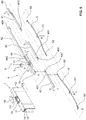
- the lowering seal has a spring-loaded lowering mechanism 4, which can be activated by means of an operating button 40.
- the lowering mechanism 4 has a first slide 41, which is connected at one end to the actuating button 40 and at the other end to a power transmission rod 42.
- the force transmission rod 42 acts on a second slide 43.
- it is connected at its second end to a third slide 43 '.
- the lowering mechanism 4 further comprises leaf springs 5, 5 '.
- a first leaf spring 5 is pivotally attached to the housing rail 1 at a first end. This forms the first fastening point 50. It is fastened to the first carrier rail part 2 in a central region. This forms the second attachment point 50. It is attached to the second slide 43 at a second end. This forms the third fastening point 52.
- the second leaf spring 5 ' is pivotally fastened to the housing rail 1 with its first end in a first fastening point 50', in a central region in a second fastening point 51 'on the second carrier profile part 2' and with a second end in a third fastening point 52 'on the third slide 43'.
- the two first fastening points 50, 50 ' are located in the region of the front ends of the seal, the two third fastening points 52, 52' are adjacent to one another.
- the actuation button 40 projects from the housing rail 1 on one end face. It is pushed in by the door frame when the door leaf is closed and thus moves the first one Slider 41 and the power transmission rod 42 in a longitudinal direction of the lowering seal. As a result, the leaf springs 5, 5 'are compressed and the support rail 2, 2' is lowered together with the sealing profile 3.
- the longitudinal force is in Figure 2a marked with the arrow A, the lowering movement with the arrow B.
- the sealing strip seals in the lowered state not only against the floor, but also in both directions of the longitudinal axis L on the end face. In the examples described here, this is achieved by the sealing strip moving outwards in both longitudinal directions.
- the sealing strip When the sealing strip is lowered, the two support rail parts 2, 2 'are moved away from one another thanks to the second and third sliders 43, 43' and their connection or coupling with the force transmission rod 42, so that their distance 6 increases from one another and they are each on one side of the Project housing rail 1 on the front.
- This is in Figure 2a represented by arrows C and D.
- a pivot axis of the lowering mechanism is denoted by S.
- the lowering seal according to the invention thus couples the lowering or raising of the sealing strip with a longitudinal displacement of the sealing strip in both longitudinal directions, the movements preferably taking place simultaneously.
- the same mechanism is also used for these movements.
- the sealing profile 3 is formed in one piece and attached to both carrier profile parts 2, 2 '.
- the sealing profile 3 is pressed outwards on both sides when the carrier profile parts 2, 2 'are moved laterally, preferably stretched. It has end sections which at least partially, preferably completely, cover the outer end faces of the carrier profile parts 2, 2 '. These sections form a hinge end 30 and a lock-side closure 31, which seal correspondingly with respect to the hinge-side frame and the lock-side frame of the door frame.
- the sealing profile 3 is preferably designed to be elastic enough so that it can be stretched or stretched when the carrier profile parts 2, 2 'are moved without tearing or without impeding the movement.
- the seal can be stretchable over the entire length or have zones, in particular central zones in the longitudinal direction, which have increased stretchability.
- the extensibility is increased at least in the longitudinal direction.
- the adjacent ends of the support rail parts 2, 2 ' are each provided with a guide plate 24, 24'. These are connected to one another with one or more guide pins 25 running in the longitudinal direction, at least one of the plates 24, 24 ′ being held displaceably along the guide pins 25.
- a first guide plate 24 fixedly connected to the guide pins 25 and a second guide plate 24 'slidably held to the guide pins.
- Figure 10 shows the arrangement with raised sealing strip, Figure 11 with the sealing strip lowered.
- the drive mechanism is shown in detail. The individual parts have already been described above and will not be repeated.
- the sliders 41, 43, 43 'and the force transmission rod 42 are preferably flat rods which are welded, screwed, riveted or otherwise connected to one another, for example via a plug connection.
- the corresponding fastening bolts or fastening points of the connections shown here have the reference numbers 420, 421, 431 and 431 ', the associated recesses or fastening points have reference numbers 410, 410', 430, 430 ', 52 and 52'.
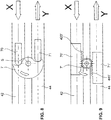
- FIG. 6 a type of coupling between the power transmission rod 42 and the second slide 43 is now also shown.
- a sliding plate 44 which is preferably arranged at the same height as the force transmission rod 42.
- the power transmission rod 42 preferably has an L-shaped recess, the displacement plate 44 forming an L-shaped counterpart to it.
- This design enables the connection in the transverse direction of the housing rail 1 to the sliders 41, 43, 43 'and the central arrangement of the force transmission element between the force transmission rod 42 and the displacement plate 44.
- the end of the second slide 43 is fixed to one end of the displacement plate 44.
- the fastening bolt is designated with the reference number 440.
- the other end region of the displacement plate 44 is operatively connected to the force transmission rod 42 via the force transmission element, here a lever connection.
- a lever 7 is fastened to a plate 110 so as to be pivotable about the pivot axis S.
- This plate is in Figure 6 shown. It is a cover plate 110, which closes an access opening 111 in the upper web 11 of the housing rail 1. It can be divided into a middle partition 13 (see Figure 5 ), preferably screw on. This design enables easy assembly of the lever 7 from above when the slides are inserted.
- a first guide cam 70 is arranged on the force transmission rod 42, a second guide cam 71 running parallel thereto is arranged on the sliding plate 44. Both Guide cams 70, 71 are in engagement with the semicircular, curved lever 7. This is in Figure 8 good to see. If the force transmission rod 42 is now pushed in the "X" direction when the door is closed, the lever 7 rotates, as with the arrow in Figure 8 shown, and pushes the slide plate 44 in the opposite direction "Y”. The sliding plate 44 thereby pushes the second slide 43 in the same direction, this movement in the Figure 6 is designated with "D”. It therefore moves in the opposite direction to the external force.
- Figure 9 shows an alternative embodiment.
- a toothed wheel 7 ' which engages in corresponding toothed racks 70', 71 '
- the toothed racks 70'. 71 ' are arranged on the force transmission rod 42 or the displacement plate 44.
- the sequence of movements is the same.
- the attachment to the cover plate 110 also.
- FIG 7 different cuts are shown, which in Figure 6 are designated.
- the housing rail has an upper groove 10 (see Figure 5 ), in which the force transmission rod 42 and the displacement plate 44 are guided so as to be displaceable.
- the lever 7 or the gear 7 ' can rotate within this groove 10.
- the middle partition 13 serves to fasten the cover plate 110.
- the upper groove 10 is delimited by an upper web 11, to which two downwardly projecting side walls 12 of the housing rail 1 adjoin and thus form a U-shaped profile which is open at the bottom.
- the upper groove 10 is delimited on its underside by a two inwardly projecting lateral webs 14, which have a passage 18 for Release connection with sliders 41, 43, 43 '.
- a vertical rib 16 projects downward from each of the lateral webs 14.
- an inner web 15 is directed inwards at the same height, so that they form a further groove for the guided displacement and mounting of the sliders 41, 43, 43 '.
- the first fastening points 50, 50 'for fastening the leaf springs 5, 5' are also located on these vertical ribs 16.
- the cross section of the housing rail 1 is preferably constant over its entire length, so that a bar profile can be used.
- the carrier rail parts 2, 2 ' are preferably made from bar profiles. They essentially have a box-shaped cross section, with a lower connecting web 26, an upper connecting web 27 and a central connecting web 20. All three webs 20, 26, 27 connect the vertically running side walls to one another. On the upper connecting web 29 there are preferably two vertical ribs 28 which run parallel to one another and protrude upward in the central region. These serve to form the second fastening points 51, 51 'for the leaf springs 5, 5'.
- the central connecting web 20 is preferably held in a groove in the stop plates 21, 21 'and the guide plates 24, 24', as in FIG Figure 3a is clearly recognizable.
- the sealing profile 3 has a U-shaped cross section with two lateral, upwardly projecting free legs 35 and a lower sealing arch 36 connecting these legs 35 to one another.
- the seal lies in the lowered state according to FIG Figure 7 with this sealing sheet 36 sealing on the floor.
- the sealing profile 3 has fastening beads 32, 33, 34 arranged one above the other along its legs, which are held in corresponding recesses in the carrier profile parts 2, 2 '. They are preferably at least in the middle
- the area of the seal ie in the area of the transition from one support profile part to another, is held in the recesses so that the seal can move more freely in the longitudinal direction relative to one another when the support profile parts 2, 2 'are moved and is not overstretched.
- the recesses preferably have a receiving opening over the entire length or over a partial area, in particular the area between the individual carrier profile parts, which is oversized in comparison to the size of the fastening beads so that the fastening beads are held, but are easily displaceable. This can be achieved in the middle area, for example, by mechanically widening the recesses or by undersizing the fastening beads.
- the legs 35 preferably protrude beyond the uppermost lateral fastening point so that they slide against the inner side walls of the housing rail 1.
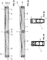
- a sealing profile 3 is shown, which is suitable for use in the lowering seals described above. It has the cross section already described.
- the trough-shaped base body is preferably an extruded profile.
- the end faces are provided with the termination 30, 31, so that the sealing profile 3 is designed to be closed on the end face.
- Each termination 30, 31 has an end face 310, two adjoining side faces 301, 311 and a bottom face 302. Side surfaces 301, 311 and base surface 302 are tightly connected, for example glued or welded, to the corresponding counterparts of the base body.
- the end faces of the sealing profile 3 can be flat as the rest of the sealing profile. However, they preferably have grooves or ribs which increase the sealing effect due to the labyrinth-like structure.
- the terminations 30, 31 are of flat design, and in turn they can be connected to the base body, for example by gluing or welding.
- FIGS 15a and 15b Another embodiment of the sealing profile 3 is shown. Only that end of the sealing profile 3 is shown which is located at the end of the seal opposite the actuating button 40. This is in in this case the end on the lock side.
- the end lying on the same side as the actuation button, here the end on the hinge side, is preferably of identical design. However, it can also be designed differently. In particular, it can be designed to be open at the end.
- the sealing profile 3 in turn has a U-shaped base body with two legs 35 and a sealing bow 36 connecting these legs 35 to one another. No fastening beads are shown here, preferably at least one on each side.
- the end face of the sealing profile 3 is in turn closed with the closure 31 on the lock side.
- this termination 31 is formed by a flat end plate 313. It is preferably made of the same material as the rest of the sealing profile 3. It is preferably made of silicone or rubber. However, it can also consist of a denser material.
- the face plate 313 is preferably watertight.
- This end plate 313 is preferably relatively thick, that is to say many times thicker than the side walls 35 and the sealing elbow 36, so that it is stiffer and more stable. However, it can also consist of two or more plates glued or welded together. In the example according to Figures 15a and 15b the end plate 313 is connected at a distance from the front edge of the sealing sheet 36 to this sheet 36 and the side walls 35, in particular glued or welded. The projecting edges of the legs 35 are provided with the reference number 350. The adhesive seams are provided with the reference number 315 in the figures.
- FIG. 15c and 15d A further exemplary embodiment of an end 31 of the sealing profile 3 is shown. These terminations can also be used on the hinge and lock side.
- the end 31 is in turn formed by a one-part or multi-part flat end plate 313.
- the end plate 313 is tapered toward the arc 36, here in one step. This tapering or recess means that the front end in the region of the arch 36 is still relatively soft and flexible, so that when the seal is lowered it can adapt optimally to the shape of the door frame and the floor and seal optimally .
- This tapered end plate 313 can be flush or spaced from the front edge 350 of the Sealing profile may be arranged.
- a sealing profile is preferably used which is approximately rectangular in shape on at least one, preferably on both end faces, and in particular has an approximately right-angled transition from the floor into the side walls in the lower region.
- the angle can also be slightly larger than 90 °. If flat end plates 313 are used, these are preferably rectangular or trapezoidal with angles deviating only slightly from 90 °.
- the degrees 31 according to the Figures 15a to 15d can be manufactured easily and inexpensively, while still guaranteeing an optimal front seal.
- the front ends 30, 31 preferably extend approximately over the entire height of the support rail parts 2, 2 '.
- the termination 30, 31 in the upper edge region 303 is preferably not fixed to the base body, but is releasable.
- the seal is particularly when using terminations 30, 31 with the shape according to the Figures 12 and 13 guaranteed anyway. This also applies when using the degrees according to Figures 14a to 15d .
- the first actuation button 40 is connected to the first slide 41, the first power transmission rod 42 and the third slide 43 '.
- the second actuation button 40 ' is connected to a left first slide 41', which is connected to a second power transmission rod 42 'and this to the second slide 43.
- the second force transmission rod 42 ′ is preferably mirror-symmetrical to the first force transmission rod 42. It is in Figure 19 good to see.
- Both rods 42, 42 ' have recesses into which the other force transmission rod 42, 42' protrude.
- there is no further reversing or power transmission element e.g. a lever 7 or a gear 7 '.
- a force transmission element can additionally be used analogously to the first example, in which case it connects the two force transmission rods 42, 42 ′ to one another.
- the first actuation button 40 thus acts via the force transmission rod 42 on the third slide 43 'and the second leaf spring 5'.
- the second actuation button 40 'acts on the second slide 43 and the first leaf spring 5 via the second force transmission rod 42'.
- the release force is thus transmitted crosswise to the springs and to the sealing strip.
- This type of bilateral triggering using leaf springs is an independent invention and is claimed here independently of the other elements, in particular regardless of the side seal, the longitudinally displaceable support rail and the trough-shaped sealing profile.
- the lowering seal is also triggered on both sides, in contrast to the embodiment according to Figure 19 a reversal of direction on both sides analogous to the embodiment according to Figure 6 takes place.
- a second actuation button 40 'and a second set of the above-mentioned elements namely the slide, the power transmission rod, the direction reversing element, the displacement plate and the leaf spring, which also lower a second carrier rail part 2' and move in the opposite direction to the external triggering force acting on the second actuating button 40 '.
- This mechanism can be used with the trough-shaped sealing profile described here or with another sealing profile, in particular a multi-part.
- the seal can have sealing elements on the end face and / or acting downwards.
- FIG. 20 to 23 A third embodiment of a sealing system according to the invention is shown.
- two seals D1, D 2 are arranged one behind the other in the transverse direction.
- the two seals are preferably identical. It is preferably the lowering seals mentioned above.
- other types of seals can also be used, in particular grinding seals.
- These two seals each have a sealing profile 3, which is trough-shaped. However, only one end face 310 is formed closed. The opposite second end face 312 is open.
- the two seals D 1 and D 2 are arranged with respect to one another in such a way that their closed end faces 310 lie opposite one another in the longitudinal direction. The door leaf T is thus sealed on both sides.
- the release button 40 is preferably located on the side opposite the closed end face 310, as shown in FIGS Figures 22 and 23 is clearly recognizable.
- the seal is an abrasive seal, as shown in the Figures 25 to 27 is shown.
- This seal in turn has a housing rail 1 with a sealing strip arranged therein.
- the housing rail 1 is fastened to a lower end face or in a lower groove of a door leaf by means of fastening brackets 9.
- the sealing strip comprises an elastomeric or rubber-elastic sealing profile 3 ', which is held in the housing rail 1. It is preferably glued to the pressure plates 22, 22 ', 22 "described below.
- the sealing profile 3 ' has, as in Figure 26 is clearly recognizable, a band-shaped flat base body, which is bent upwards at its two opposite ends. It forms a stop surface 38. At least one outwardly directed rib 37 is formed on this base body. It extends over the entire length and up to the ends of the regions of the base body which are bent upwards. There are preferably several ribs. In this example there are two ribs 37.
- Stop plates 21, 21 ', 21 are also rigidly fastened to the housing rail.
- the side stop plates 21, 21' are preferably fastened to the upper web 11 of the housing rail 1, the lower stop plate 21" preferably to the two side walls 12 of the housing rail 1
- one or more guide pins 23, 23 ', 23 are slidably held in these stop plates 21, 21', 21", which are firmly connected to pressure plates 22, 22 ', 22 ".
- the downward horizontal Pressure plate 22 "preferably extends approximately over the entire length and width of the sealing profile 3 'and presses against the stop surface 38.
- the side pressure plates 22, 22' preferably extend over the entire height and width of the end face of the sealing profile and also press on the stop surface 38. This stop surface 38 is preferably flat.
- two or more such pressure plates 22" can also be arranged one behind the other in the longitudinal direction of the seal and attached individually to the housing rail. This has the advantage that the sealing profile 3 'can be moved downwards independently of one another at two or more points. This is with the vertical arrows in the Figure 26 shown. This means that the grinding seal can be easily adapted to uneven floors.
- stop plate 21, 21 ', 21 "and pressure plate 22, 22', 22" can be set by means of adjusting screws with the aid of a hand tool 8. In this way, the lateral and downward contact pressure of the grinding seal can also be set on site with the grinding seal shown here.
- FIG 27c Another embodiment of the sealing profile 3 'is shown. Instead of rounded corners, the corner here is rectangular. This has the advantage that it seals optimally in the corner of the door frame.
- This sealing profile 3 ' can also be used with an actuating mechanism, as is shown in FIG Figures 1 to 19 or the Figures 28a and 28b use. In these cases, the sealing profile 3 'is arranged on the carrier rail parts 2, 2' and is pressed laterally by them and preferably also downwards.
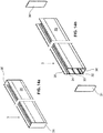
- FIG. 28a and 28b shows a variant which can be used, for example, in the exemplary embodiments described above.
- This variant can be used at the hinge and / or lock end of the seal.
- the carrier rail in turn has a first carrier rail part 2 and a stop plate 21 connected thereto and a pressure plate 22.
- Guide pins 23 and an adjusting screw 29 allow the adjustable connection between the parts.
- the upper connecting web of the first carrier rail part 2 is again provided with the reference number 27 and the lower connecting web with the reference number 26.
- a sealing pad 220 is attached to the underside of the pressure plate 22. This preferably extends in the transverse direction of the seal over the entire width of the pressure plate 22. In the longitudinal direction of the seal, the sealing pad 220 is longer than the pressure plate 22 and preferably extends over the stop plate 21 to the lower connecting web 26. However, it preferably does not extend over the entire length of the seal is only present in one or both front end areas of the seal.
- the sealing pad 220 is preferably only attached to the pressure plate 22 and can move freely relative to the stop plate 21 and to the lower connecting web 26.
- the sealing pad 220 preferably has the shape of a flat cuboid. It is preferably soft and consists, for example, of foam rubber, silicone or rubber. However, it can also be stiff and hard, for example made of a thermoset.
- the sealing pad 220 is in the assembled state of the seal between the support rail 2 and the sealing sheet 36 and thus optimizes the seal in the lower corner area of the seal.
- a reinforcement plate 304 is also shown on the end face behind the end closure 30. However, this reinforcement plate 304 is optional.
- a seal is schematically shown as it is arranged in a door leaf T.
- the two sides of the door frame are labeled R 1 , R 2 .
- the floor on which the lowered seal rests is labeled B.
- the actuating button 40 is pressed in and has moved the carrier rail 2 and the sealing profile 3 to the left towards the lock-side door frame side R 2 via the lowering mechanism, not shown.
- the sealing profile 3 is thus on this side of the door frame.
- the sealing profile 3 is preferably designed to be closed on this end face.
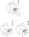
- the button 40 here the hinge side, a recess 49 in the door frame.
- An additional module is arranged in this recess, which includes a stop 45, a return spring 46, a lever mechanism 47 and a sealing body 48.
- the additional module preferably has a housing or a frame to accommodate these elements.
- FIG 30a the situation is shown with the door open.
- the sealing body 48 is preferably aligned with the surrounding surface of the door frame. It also seals the opening that it penetrates.
- Figure 30b the possible directions of movement of the sealing body 48 are represented by arrows, it being able to be actuated by means of the lever mechanism 47.
- Figure 30c it is shown that in the lowered state of the seal, the end of the sealing profile 3 rests on the sealing body 48 and this end and corner region is thereby sealed.
- the actuation button 40 does not press the door frame itself when closing the door leaf T, but on the stop 45 of the additional module. This stop 45 is pressed against the spring force of the return spring 46 deeper into the door frame until the counterforce is sufficient to press in the actuation button 40 and to lower the carrier rail 2 with the sealing profile 3 in a known manner.
- the displacement of the stop 45 has the result that the lever mechanism 47 connected to it is actuated, which in the opposite direction, i.e. in the direction parallel to the displacement of the actuating button 45, the sealing body 48 moves out of the door frame, wherein it is still held in the door frame and seals the recess 49 with its circumference.
- the sealing body 48 rests on the one hand on the bottom B and seals downward. On the other hand, it contacts the front end of the sealing profile 3 and seals together with it on the front side.
- the lever mechanism is preferably designed and adjusted in such a way that it ensures a downward and / or frontal contact pressure.
- the sealing profile 3 can be designed to be open on this end face. Preferably it is however, formed closed, and more preferably as described above.
- the sealing body 48 is preferably made of the same material as the sealing profile 3, in particular silicone or rubber. It is preferably soft and / or flexible in order to ensure an optimal seal. However, it can also be rigid and in particular consist of a thermoset. It is preferably water-tight.
- the additional module can be activated by an additional trigger element, which interacts or is operatively connected to the trigger element of the sealing strip, that is to say to the actuating button mentioned above.
- the seal according to the invention enables a single sealing line which encompasses both front sides and the lower area of the seal and thus can also seal the lower corner area of the door frame. It thus provides optimal protection against driving rain and flooding, while still being relatively simple and slim.
Landscapes
- Engineering & Computer Science (AREA)
- Civil Engineering (AREA)
- Structural Engineering (AREA)
- Specific Sealing Or Ventilating Devices For Doors And Windows (AREA)
Claims (19)
- Dispositif d'étanchéité pour un vantail de porte ou de fenêtre, le dispositif d'étanchéité possédant un rail de boîtier (1) rectiligne et une baguette d'étanchéité (2, 2', 2", 3, 3') maintenue dans celui-ci et la baguette d'étanchéité (2, 2', 2", 3, 3') possédant un profil d'étanchéité (3) qui réalise l'étanchéité vers le bas par rapport à un fond, caractérisé en ce que le profil d'étanchéité (3) est fermé du côté frontal sur au moins un côté, le profil d'étanchéité (3) réalisant l'étanchéité du côté frontal sur ce côté par rapport à une surface latérale verticale.
- Dispositif d'étanchéité selon la revendication 1, la baguette d'étanchéité (3, 3') réalisant l'étanchéité par rapport à des surfaces latérales verticales du côté frontal sur deux côtés mutuellement opposés.
- Dispositif d'étanchéité selon l'une des revendications 1 et 2, la baguette d'étanchéité (2, 2', 2", 3, 3') possédant une unité porteuse (2, 2', 2") à laquelle est fixé le profil d'étanchéité (3, 3'), l'au moins un côté frontal fermé du profil d'étanchéité (3, 3') pouvant coulisser dans la direction longitudinale (L) du rail de boîtier (1) au moyen d'une plaque de pressage (22, 22') réglable de l'unité porteuse (2, 2', 2").
- Dispositif d'étanchéité selon la revendication 3, un coussin d'étanchéité (220) étant disposé au niveau d'un côté inférieur de la plaque de pressage (22, 22'), lequel, à l'état abaissé de la garniture d'étanchéité, remplit une zone de coin inférieure côté frontal du profil d'étanchéité (3).
- Dispositif d'étanchéité selon l'une des revendications 1 à 4, le profil d'étanchéité (3) étant réalisé expansible le long de sa direction longitudinale.
- Dispositif d'étanchéité selon l'une des revendications 1 à 5, la baguette d'étanchéité (3) étant réalisée en forme de cuvette, au moins un côté frontal (30, 31) du profil d'étanchéité (3) étant de configuration fermée et la baguette d'étanchéité (3) étant de configuration ouverte vers l'extérieur.
- Dispositif d'étanchéité selon la revendication 6, les deux côtés frontaux (30, 31) du profil d'étanchéité (3) en forme de cuvette étant de configuration fermée.
- Dispositif d'étanchéité selon l'une des revendications 6 à 7, le profil d'étanchéité possédant un corps de base ayant une section transversale sensiblement en forme de U avec deux branches (35) et un élément jointif (36) qui relie les branches (35) l'une à l'autre, l'élément jointif formant un coude d'étanchéité destiné à reposer de manière étanche sur le fond.
- Dispositif d'étanchéité selon la revendication 8, une terminaison (30, 31) se trouvant au niveau d'au moins un côté frontal fermé, laquelle est reliée au corps de base par fusion de matières, notamment par collage ou soudage.
- Dispositif d'étanchéité selon la revendication 9, la terminaison (30, 31) étant formée par au moins une plaque plane (313, 314).
- Dispositif d'étanchéité selon l'une des revendications 8 à 10, le coude d'étanchéité (36), à l'état assemblé de la garniture d'étanchéité, formant dans la zone de la terminaison (30, 31) un angle d'approximativement 90° avec chacune des deux branches (35).
- Dispositif d'étanchéité selon l'une des revendications 8 à 11, le corps de base étant de configuration monobloc en section transversale.
- Dispositif d'étanchéité selon l'une des revendications 6 à 12, le profil d'étanchéité (3) possédant sur son côté intérieur au moins un bourrelet de fixation (32, 33, 34) servant à la fixation au rail porteur (2, 2').
- Dispositif d'étanchéité selon la revendication 13, deux ou trois bourrelets de fixation étant disposés espacés les uns au-dessus des autres sur le même côté intérieur du profil d'étanchéité.
- Dispositif d'étanchéité selon l'une des revendications 1 à 14, lequel est un dispositif d'étanchéité à abaissement automatique.
- Dispositif d'étanchéité selon l'une des revendications 1 à 5, le profil d'étanchéité (3') possédant un corps de base (38) plat en forme de bande pourvue d'une zone qui suit un tracé horizontal et des extrémités côté frontal courbées vers le haut.
- Dispositif d'étanchéité selon la revendication 16, des nervures (37) faisant saillie vers l'extérieur étant disposées sur le corps de base (38).
- Dispositif d'étanchéité selon l'une des revendications 16 et 17, au moins une plaque de pressage (22") horizontale réglable étant présente et la zone qui suit un tracé horizontal pouvant être décalée vers le bas au moyen de cette plaque de pressage (22") horizontale.
- Système d'étanchéité comprenant deux dispositifs d'étanchéité selon l'une des revendications 1 à 18, les deux dispositifs d'étanchéité étant disposés parallèlement l'un à l'autre, chaque dispositif d'étanchéité réalisant l'étanchéité unilatéralement du côté frontal et étant de configuration ouverte de l'autre côté et les deux dispositifs d'étanchéité rendant ensemble étanches deux côtés frontaux opposés du système d'étanchéité.
Applications Claiming Priority (3)
| Application Number | Priority Date | Filing Date | Title |
|---|---|---|---|
| EP14190501 | 2014-10-27 | ||
| EP14190499 | 2014-10-27 | ||
| PCT/EP2015/074726 WO2016066576A1 (fr) | 2014-10-27 | 2015-10-26 | Dispositif d'étanchéité |
Publications (2)
| Publication Number | Publication Date |
|---|---|
| EP3212874A1 EP3212874A1 (fr) | 2017-09-06 |
| EP3212874B1 true EP3212874B1 (fr) | 2020-07-29 |
Family
ID=54347563
Family Applications (2)
| Application Number | Title | Priority Date | Filing Date |
|---|---|---|---|
| EP15797262.1A Active EP3212875B1 (fr) | 2014-10-27 | 2015-10-26 | Dispositif d'étanchéité |
| EP15784728.6A Active EP3212874B1 (fr) | 2014-10-27 | 2015-10-26 | Dispositif d'étanchéité |
Family Applications Before (1)
| Application Number | Title | Priority Date | Filing Date |
|---|---|---|---|
| EP15797262.1A Active EP3212875B1 (fr) | 2014-10-27 | 2015-10-26 | Dispositif d'étanchéité |
Country Status (8)
| Country | Link |
|---|---|
| US (2) | US20180291673A1 (fr) |
| EP (2) | EP3212875B1 (fr) |
| JP (2) | JP2017535699A (fr) |
| KR (2) | KR20170076760A (fr) |
| CN (2) | CN107075900B (fr) |
| AU (2) | AU2015340758B2 (fr) |
| SG (2) | SG11201703300RA (fr) |
| WO (2) | WO2016066577A2 (fr) |
Families Citing this family (26)
| Publication number | Priority date | Publication date | Assignee | Title |
|---|---|---|---|---|
| KR20170126868A (ko) * | 2015-01-15 | 2017-11-20 | 플래닛 지디제트 아게 | 무문턱 도어용 시일 |
| EP3112577B1 (fr) * | 2015-07-01 | 2017-08-30 | Planet GDZ AG | Joint abaissable |
| AT518428B1 (de) * | 2016-08-23 | 2017-10-15 | Ing Degelsegger Walter | Schwenkbarer Tür- oder Fensterflügel |
| CA3048900A1 (fr) * | 2017-01-05 | 2018-07-12 | Aurora Systems Inc. | Porte coulissante suspendue comprenant un guide inferieur et un joint |
| US10865599B2 (en) * | 2017-06-29 | 2020-12-15 | The Boeing Company | Seal assembly for a galley door of a galley and method of assembling a galley with a seal assembly |
| EP3502406A1 (fr) | 2017-12-19 | 2019-06-26 | Planet GDZ AG | Vantail de porte doté d'un système d'étanchéité |
| US10934772B2 (en) * | 2018-02-19 | 2021-03-02 | Tucson Rolling Shutters, Inc. | Self-adjusting bottom bar for a retractable screen |
| DE102018204075A1 (de) * | 2018-03-16 | 2019-09-19 | eds electric drive solution GmbH & Co. KG | Dichteinheit für eine Gebäudetür |
| WO2019179937A1 (fr) | 2018-03-19 | 2019-09-26 | Planet Gdz Ag | Dispositif d'étanchéité |
| EP3768931B1 (fr) | 2018-03-19 | 2024-01-17 | ASSA ABLOY (Schweiz) AG | Unité d'étanchéité |
| CN110552608B (zh) * | 2018-05-31 | 2024-08-23 | 北京天乐交控科技发展有限公司 | 塞拉门密封结构 |
| KR102120222B1 (ko) | 2018-10-19 | 2020-06-08 | 서준영 | 도어 자동 실링장치 |
| CN109282033B (zh) * | 2018-10-29 | 2020-08-04 | 中车戚墅堰机车有限公司 | 机车非接触密封结构 |
| CN109826495B (zh) * | 2019-03-07 | 2023-10-24 | 宁波市维特建筑五金有限公司 | 一种门窗传动锁闭器 |
| EP3712369A1 (fr) | 2019-03-18 | 2020-09-23 | ASSA ABLOY (Schweiz) AG | Dispositif de joint d'étanchéité |
| CN110316208A (zh) * | 2019-05-27 | 2019-10-11 | 南京康尼机电股份有限公司 | 一种轨道车辆密闭门 |
| CN210463300U (zh) * | 2019-08-09 | 2020-05-05 | 广东美的制冷设备有限公司 | 用于窗式空调器的密封装置及具有其的窗式空调器 |
| DE102019126666B4 (de) | 2019-10-02 | 2022-06-09 | Honerkamp Industrievertriebs GmbH | Vorrichtung zum Schutz vor einem Wassereinbruch sowie eine Tür oder ein Fenster mit einer solchen Vorrichtung |
| DE102019135252A1 (de) | 2019-12-19 | 2021-06-24 | Baugruppentechnik Pollmeier Gmbh | Schiebetür und Trockenbau-Tragrahmen mit einer Schiebetür |
| DE102019135251A1 (de) * | 2019-12-19 | 2021-06-24 | Baugruppentechnik Pollmeier Gmbh | Trockenbau-Tragrahmen für eine Schallschutz-Schiebetür |
| EP4026978A1 (fr) * | 2021-01-11 | 2022-07-13 | Athmer OHG | Joint d'étanchéité automatique pour une porte à double battant doté d'un revers |
| US11761262B2 (en) * | 2021-05-03 | 2023-09-19 | National Guard Products, Inc. | Method, system and apparatus for controlling excessive gaps of a door bottom |
| US11873677B2 (en) | 2021-09-28 | 2024-01-16 | Westhampton Architectural Glass, Inc. | Fenestration system with actuatable sealing device, and related devices, systems, and methods |
| DE102022115569B9 (de) | 2022-06-22 | 2024-03-07 | KÜFFNER Aluzargen GmbH & Co. OHG | Schallschutztür |
| EP4382713A1 (fr) * | 2022-12-08 | 2024-06-12 | ASSA ABLOY (Schweiz) AG | Dispositif d'étanchéité |
| CN116357209B (zh) * | 2023-01-03 | 2024-03-26 | 广东玫瑰岛家居股份有限公司 | 一种无地轨式防溅水淋浴房 |
Family Cites Families (35)
| Publication number | Priority date | Publication date | Assignee | Title |
|---|---|---|---|---|
| US1452703A (en) * | 1920-06-23 | 1923-04-24 | Henry V Pollard | Threshold eliminator |
| US4395854A (en) * | 1980-12-15 | 1983-08-02 | American Standard Inc. | Universal latch means for drop seal assembly for a moveable wall |
| DE3329829A1 (de) * | 1983-08-18 | 1985-02-28 | Hans-Joachim 6350 Bad Nauheim Bayer | Einrichtung zum abdichten ruhender teile sowie teile mit einer solchen einrichtung |
| DE3427938A1 (de) * | 1984-02-28 | 1985-09-12 | Fa. F. Athmer, 5760 Arnsberg | Automatische dichtungsvorrichtung fuer einen unteren tuerspalt |
| ES1002297Y (es) * | 1987-03-20 | 1990-02-16 | Berniola Gil Antonio | Nuevo burlete para el extremo inferior de las puertas y similares |
| FI88332C (fi) | 1988-04-19 | 1993-04-26 | Planet Matthias Jaggi | Taetningsanordning foer en troeskelloes doerr |
| EP0509961B1 (fr) | 1991-04-17 | 1994-12-14 | Planet MJT AG | Dispositif d'étanchéité, particulièrement pour battants de portes |
| CH688741A5 (de) * | 1994-06-01 | 1998-02-13 | Matthias Jaggi | Dichtungsvorrichtung, insbesondere für Türflügel. |
| JPH08170473A (ja) * | 1994-12-16 | 1996-07-02 | Yagi:Kk | 扉の密閉装置 |
| JP3015271B2 (ja) * | 1994-12-22 | 2000-03-06 | 株式会社ニチベイ | 扉のシールジャッキ機構 |
| US6125584A (en) * | 1994-12-29 | 2000-10-03 | Pemko Manufacturing Co. | Automatic door bottom |
| JPH10292748A (ja) * | 1997-04-21 | 1998-11-04 | Sankyo Alum Ind Co Ltd | サッシ |
| EP1033467B1 (fr) * | 1999-03-02 | 2006-08-30 | Luis Müller Carranza | Bande d'étanchéité |
| IE20000330A1 (en) * | 2000-05-03 | 2001-11-14 | Brian C Allport | Weather excluder system |
| CN2433384Y (zh) * | 2000-07-27 | 2001-06-06 | 马龙建筑及机械(天津)有限公司 | 房门门底密封挡板 |
| CN2441960Y (zh) * | 2000-08-28 | 2001-08-08 | 祖国玉 | 自动伸缩门缝挡条 |
| CN2570424Y (zh) * | 2002-09-29 | 2003-09-03 | 程树斌 | 平开门密封装置 |
| US20040111972A1 (en) * | 2002-12-16 | 2004-06-17 | Planet Gdz Ag | Sill-free door with lowerable seal |
| DE202005011984U1 (de) * | 2005-07-30 | 2005-10-13 | Fa. F. Athmer | Dichtungsanordnung für eine Schiebetür |
| US7665245B2 (en) * | 2005-12-30 | 2010-02-23 | Speyer Door And Window, Inc. | Sealing system positioned within frame for door/window |
| EP2426297B1 (fr) * | 2006-11-13 | 2013-12-25 | Van der Kooij, Johannes Jacob Hans Willem | Ensemble comportant un panneau mobile, par exemple une porte ou fenêtre battante et son mécanisme de verrouillage |
| AU2007237192B2 (en) | 2006-11-22 | 2013-09-05 | Raven Products Pty Ltd | Automatic Threshold Seal |
| AU2012100490A4 (en) | 2006-11-22 | 2012-05-24 | Raven Products Pty Ltd | Automatic Threshold Seal |
| US7469502B1 (en) * | 2007-02-27 | 2008-12-30 | Jonathan Steel | Window shutter system |
| EP3165703B1 (fr) | 2008-02-04 | 2021-05-19 | ASSA ABLOY (Schweiz) AG | Dispositif d'étanchéité abaissable |
| JP3142738U (ja) * | 2008-03-24 | 2008-06-26 | プラネット ゲーデーツェット アーゲー | シール部材、及びケース体 |
| CN102086751A (zh) * | 2009-12-07 | 2011-06-08 | 李雪平 | 安全门 |
| GB201014833D0 (en) * | 2010-09-07 | 2010-10-20 | Rbp Associates Ltd | Drop-down door seal |
| JP5687530B2 (ja) * | 2011-03-08 | 2015-03-18 | 株式会社シブタニ | ドアボトムのシール装置 |
| DE202011051326U1 (de) * | 2011-09-16 | 2012-12-17 | Athmer Ohg | Dichtung für Türen, Fenster oder Ähnlichem mit einer absenkbaren Dichtleiste |
| CN103443383B (zh) * | 2011-09-30 | 2015-09-09 | 韦伯太克控股公司 | 用于摆门的密封组件 |
| AU2012100488A4 (en) | 2012-04-27 | 2012-05-24 | Raven Products Pty Ltd | Door drop seal and escutcheon plate with a dampening device |
| US9803418B2 (en) * | 2012-07-30 | 2017-10-31 | Planet Gdz Ag | Drop-down seal and building part |
| CN104736790B (zh) * | 2012-08-23 | 2017-05-10 | 普兰特Gdz股份公司 | 具有两个密封平面的门密封件 |
| US9816314B2 (en) * | 2013-02-12 | 2017-11-14 | Norman David Eansor | Inflatable weatherstrip system |
-
2015
- 2015-10-26 EP EP15797262.1A patent/EP3212875B1/fr active Active
- 2015-10-26 KR KR1020177014392A patent/KR20170076760A/ko unknown
- 2015-10-26 WO PCT/EP2015/074727 patent/WO2016066577A2/fr active Application Filing
- 2015-10-26 US US15/522,537 patent/US20180291673A1/en not_active Abandoned
- 2015-10-26 AU AU2015340758A patent/AU2015340758B2/en not_active Ceased
- 2015-10-26 EP EP15784728.6A patent/EP3212874B1/fr active Active
- 2015-10-26 WO PCT/EP2015/074726 patent/WO2016066576A1/fr active Application Filing
- 2015-10-26 SG SG11201703300RA patent/SG11201703300RA/en unknown
- 2015-10-26 KR KR1020177014394A patent/KR20170072334A/ko unknown
- 2015-10-26 CN CN201580058708.5A patent/CN107075900B/zh not_active Expired - Fee Related
- 2015-10-26 SG SG11201703303QA patent/SG11201703303QA/en unknown
- 2015-10-26 US US15/522,508 patent/US20180291674A1/en not_active Abandoned
- 2015-10-26 CN CN201580058710.2A patent/CN107002457A/zh active Pending
- 2015-10-26 JP JP2017522500A patent/JP2017535699A/ja not_active Ceased
- 2015-10-26 JP JP2017522478A patent/JP2017535698A/ja active Pending
- 2015-10-26 AU AU2015340757A patent/AU2015340757B2/en not_active Ceased
Non-Patent Citations (1)
| Title |
|---|
| None * |
Also Published As
| Publication number | Publication date |
|---|---|
| US20180291673A1 (en) | 2018-10-11 |
| KR20170072334A (ko) | 2017-06-26 |
| WO2016066576A1 (fr) | 2016-05-06 |
| CN107002457A (zh) | 2017-08-01 |
| KR20170076760A (ko) | 2017-07-04 |
| JP2017535698A (ja) | 2017-11-30 |
| EP3212875B1 (fr) | 2020-11-25 |
| JP2017535699A (ja) | 2017-11-30 |
| WO2016066577A2 (fr) | 2016-05-06 |
| AU2015340758A1 (en) | 2017-05-18 |
| AU2015340757A1 (en) | 2017-05-18 |
| EP3212874A1 (fr) | 2017-09-06 |
| CN107075900B (zh) | 2020-04-17 |
| EP3212875A2 (fr) | 2017-09-06 |
| WO2016066577A3 (fr) | 2016-08-04 |
| US20180291674A1 (en) | 2018-10-11 |
| CN107075900A (zh) | 2017-08-18 |
| SG11201703300RA (en) | 2017-05-30 |
| AU2015340758B2 (en) | 2018-12-06 |
| SG11201703303QA (en) | 2017-06-29 |
| AU2015340757B2 (en) | 2018-12-13 |
Similar Documents
| Publication | Publication Date | Title |
|---|---|---|
| EP3212874B1 (fr) | Dispositif d'étanchéité | |
| DE10136681C2 (de) | Rahmengestell | |
| EP0841456B1 (fr) | Fenêtre du type jalousie pour des façades essentiellement verticales | |
| EP1279775B1 (fr) | Conteneur | |
| EP2888428B1 (fr) | Joint descendant et élément de construction | |
| DE69936554T2 (de) | Eckpfosten für Schaltschrank und damit ausgerüsteter Schaltschrank | |
| EP2554774B1 (fr) | Joint pour une porte sans seuil | |
| DE102008023500A1 (de) | Tür mit einer Bodendichtung | |
| EP3768931B1 (fr) | Unité d'étanchéité | |
| EP1717405A1 (fr) | Dispositif d'étanchéité pour porte | |
| EP4060158A1 (fr) | Paroi coulissante pourvue d'agencement d'étanchéité | |
| EP3112577B1 (fr) | Joint abaissable | |
| EP2851501B1 (fr) | Porte sectionnelle | |
| DE19751657C2 (de) | Glaswand für Dachgeschoßräume unter einem geneigten Dach | |
| EP1279791B1 (fr) | Joint d'étanchéité descendant pour porte | |
| EP2088277B1 (fr) | Agencement d'étanchéité pour une porte sans seuil | |
| DE10037329A1 (de) | Sektionalhub- oder Falttor | |
| WO2009147131A1 (fr) | Dispositif destiné à rendre les portes étanches vis-à-vis du sol | |
| EP2182157B1 (fr) | Ecran pour un espace entre un dormant de porte ou de portail et intrados | |
| AT510200B1 (de) | Flexibles raumbelüftungssystem | |
| DE202005007998U1 (de) | Abdichtung | |
| DE202005003560U1 (de) | Vorrichtung zur Abdichtung von Türen | |
| EP3985219A1 (fr) | Agencement doté d'un joint d'étanchéité de plancher pour une porte, un espace intermédiaire se trouvant entre un battant de porte et un cadre, dans lequel passe le seul axe de rotation du battant | |
| EP2868849A1 (fr) | Agencement d'éléments coulissants | |
| EP2657445A1 (fr) | Volets coulissants et pliables manuels ou motorisés |
Legal Events
| Date | Code | Title | Description |
|---|---|---|---|
| STAA | Information on the status of an ep patent application or granted ep patent |
Free format text: STATUS: THE INTERNATIONAL PUBLICATION HAS BEEN MADE |
|
| PUAI | Public reference made under article 153(3) epc to a published international application that has entered the european phase |
Free format text: ORIGINAL CODE: 0009012 |
|
| STAA | Information on the status of an ep patent application or granted ep patent |
Free format text: STATUS: REQUEST FOR EXAMINATION WAS MADE |
|
| 17P | Request for examination filed |
Effective date: 20170510 |
|
| AK | Designated contracting states |
Kind code of ref document: A1 Designated state(s): AL AT BE BG CH CY CZ DE DK EE ES FI FR GB GR HR HU IE IS IT LI LT LU LV MC MK MT NL NO PL PT RO RS SE SI SK SM TR |
|
| AX | Request for extension of the european patent |
Extension state: BA ME |
|
| DAV | Request for validation of the european patent (deleted) | ||
| DAX | Request for extension of the european patent (deleted) | ||
| STAA | Information on the status of an ep patent application or granted ep patent |
Free format text: STATUS: EXAMINATION IS IN PROGRESS |
|
| 17Q | First examination report despatched |
Effective date: 20190516 |
|
| GRAP | Despatch of communication of intention to grant a patent |
Free format text: ORIGINAL CODE: EPIDOSNIGR1 |
|
| STAA | Information on the status of an ep patent application or granted ep patent |
Free format text: STATUS: GRANT OF PATENT IS INTENDED |
|
| INTG | Intention to grant announced |
Effective date: 20200211 |
|
| RIN1 | Information on inventor provided before grant (corrected) |
Inventor name: DINTHEER, ANDREAS Inventor name: EICHELBERGER, DANIEL |
|
| GRAS | Grant fee paid |
Free format text: ORIGINAL CODE: EPIDOSNIGR3 |
|
| GRAA | (expected) grant |
Free format text: ORIGINAL CODE: 0009210 |
|
| STAA | Information on the status of an ep patent application or granted ep patent |
Free format text: STATUS: THE PATENT HAS BEEN GRANTED |
|
| AK | Designated contracting states |
Kind code of ref document: B1 Designated state(s): AL AT BE BG CH CY CZ DE DK EE ES FI FR GB GR HR HU IE IS IT LI LT LU LV MC MK MT NL NO PL PT RO RS SE SI SK SM TR |
|
| RAP1 | Party data changed (applicant data changed or rights of an application transferred) |
Owner name: ASSA ABLOY (SCHWEIZ) AG |
|
| REG | Reference to a national code |
Ref country code: CH Ref legal event code: EP Ref country code: CH Ref legal event code: NV Representative=s name: ISLER AND PEDRAZZINI AG, CH |
|
| REG | Reference to a national code |
Ref country code: AT Ref legal event code: REF Ref document number: 1295996 Country of ref document: AT Kind code of ref document: T Effective date: 20200815 |
|
| REG | Reference to a national code |
Ref country code: IE Ref legal event code: FG4D Free format text: LANGUAGE OF EP DOCUMENT: GERMAN |
|
| REG | Reference to a national code |
Ref country code: DE Ref legal event code: R096 Ref document number: 502015013131 Country of ref document: DE |
|
| REG | Reference to a national code |
Ref country code: NL Ref legal event code: FP |
|
| REG | Reference to a national code |
Ref country code: LT Ref legal event code: MG4D |
|
| PG25 | Lapsed in a contracting state [announced via postgrant information from national office to epo] |
Ref country code: ES Free format text: LAPSE BECAUSE OF FAILURE TO SUBMIT A TRANSLATION OF THE DESCRIPTION OR TO PAY THE FEE WITHIN THE PRESCRIBED TIME-LIMIT Effective date: 20200729 Ref country code: BG Free format text: LAPSE BECAUSE OF FAILURE TO SUBMIT A TRANSLATION OF THE DESCRIPTION OR TO PAY THE FEE WITHIN THE PRESCRIBED TIME-LIMIT Effective date: 20201029 Ref country code: SE Free format text: LAPSE BECAUSE OF FAILURE TO SUBMIT A TRANSLATION OF THE DESCRIPTION OR TO PAY THE FEE WITHIN THE PRESCRIBED TIME-LIMIT Effective date: 20200729 Ref country code: HR Free format text: LAPSE BECAUSE OF FAILURE TO SUBMIT A TRANSLATION OF THE DESCRIPTION OR TO PAY THE FEE WITHIN THE PRESCRIBED TIME-LIMIT Effective date: 20200729 Ref country code: LT Free format text: LAPSE BECAUSE OF FAILURE TO SUBMIT A TRANSLATION OF THE DESCRIPTION OR TO PAY THE FEE WITHIN THE PRESCRIBED TIME-LIMIT Effective date: 20200729 Ref country code: GR Free format text: LAPSE BECAUSE OF FAILURE TO SUBMIT A TRANSLATION OF THE DESCRIPTION OR TO PAY THE FEE WITHIN THE PRESCRIBED TIME-LIMIT Effective date: 20201030 Ref country code: FI Free format text: LAPSE BECAUSE OF FAILURE TO SUBMIT A TRANSLATION OF THE DESCRIPTION OR TO PAY THE FEE WITHIN THE PRESCRIBED TIME-LIMIT Effective date: 20200729 Ref country code: PT Free format text: LAPSE BECAUSE OF FAILURE TO SUBMIT A TRANSLATION OF THE DESCRIPTION OR TO PAY THE FEE WITHIN THE PRESCRIBED TIME-LIMIT Effective date: 20201130 Ref country code: NO Free format text: LAPSE BECAUSE OF FAILURE TO SUBMIT A TRANSLATION OF THE DESCRIPTION OR TO PAY THE FEE WITHIN THE PRESCRIBED TIME-LIMIT Effective date: 20201029 |
|
| PG25 | Lapsed in a contracting state [announced via postgrant information from national office to epo] |
Ref country code: RS Free format text: LAPSE BECAUSE OF FAILURE TO SUBMIT A TRANSLATION OF THE DESCRIPTION OR TO PAY THE FEE WITHIN THE PRESCRIBED TIME-LIMIT Effective date: 20200729 Ref country code: LV Free format text: LAPSE BECAUSE OF FAILURE TO SUBMIT A TRANSLATION OF THE DESCRIPTION OR TO PAY THE FEE WITHIN THE PRESCRIBED TIME-LIMIT Effective date: 20200729 Ref country code: PL Free format text: LAPSE BECAUSE OF FAILURE TO SUBMIT A TRANSLATION OF THE DESCRIPTION OR TO PAY THE FEE WITHIN THE PRESCRIBED TIME-LIMIT Effective date: 20200729 Ref country code: IS Free format text: LAPSE BECAUSE OF FAILURE TO SUBMIT A TRANSLATION OF THE DESCRIPTION OR TO PAY THE FEE WITHIN THE PRESCRIBED TIME-LIMIT Effective date: 20201129 |
|
| PG25 | Lapsed in a contracting state [announced via postgrant information from national office to epo] |
Ref country code: EE Free format text: LAPSE BECAUSE OF FAILURE TO SUBMIT A TRANSLATION OF THE DESCRIPTION OR TO PAY THE FEE WITHIN THE PRESCRIBED TIME-LIMIT Effective date: 20200729 Ref country code: RO Free format text: LAPSE BECAUSE OF FAILURE TO SUBMIT A TRANSLATION OF THE DESCRIPTION OR TO PAY THE FEE WITHIN THE PRESCRIBED TIME-LIMIT Effective date: 20200729 Ref country code: SM Free format text: LAPSE BECAUSE OF FAILURE TO SUBMIT A TRANSLATION OF THE DESCRIPTION OR TO PAY THE FEE WITHIN THE PRESCRIBED TIME-LIMIT Effective date: 20200729 Ref country code: DK Free format text: LAPSE BECAUSE OF FAILURE TO SUBMIT A TRANSLATION OF THE DESCRIPTION OR TO PAY THE FEE WITHIN THE PRESCRIBED TIME-LIMIT Effective date: 20200729 Ref country code: CZ Free format text: LAPSE BECAUSE OF FAILURE TO SUBMIT A TRANSLATION OF THE DESCRIPTION OR TO PAY THE FEE WITHIN THE PRESCRIBED TIME-LIMIT Effective date: 20200729 |
|
| REG | Reference to a national code |
Ref country code: DE Ref legal event code: R097 Ref document number: 502015013131 Country of ref document: DE |
|
| PG25 | Lapsed in a contracting state [announced via postgrant information from national office to epo] |
Ref country code: AL Free format text: LAPSE BECAUSE OF FAILURE TO SUBMIT A TRANSLATION OF THE DESCRIPTION OR TO PAY THE FEE WITHIN THE PRESCRIBED TIME-LIMIT Effective date: 20200729 |
|
| PLBE | No opposition filed within time limit |
Free format text: ORIGINAL CODE: 0009261 |
|
| STAA | Information on the status of an ep patent application or granted ep patent |
Free format text: STATUS: NO OPPOSITION FILED WITHIN TIME LIMIT |
|
| GBPC | Gb: european patent ceased through non-payment of renewal fee |
Effective date: 20201029 |
|
| PG25 | Lapsed in a contracting state [announced via postgrant information from national office to epo] |
Ref country code: SK Free format text: LAPSE BECAUSE OF FAILURE TO SUBMIT A TRANSLATION OF THE DESCRIPTION OR TO PAY THE FEE WITHIN THE PRESCRIBED TIME-LIMIT Effective date: 20200729 Ref country code: MC Free format text: LAPSE BECAUSE OF FAILURE TO SUBMIT A TRANSLATION OF THE DESCRIPTION OR TO PAY THE FEE WITHIN THE PRESCRIBED TIME-LIMIT Effective date: 20200729 Ref country code: LU Free format text: LAPSE BECAUSE OF NON-PAYMENT OF DUE FEES Effective date: 20201026 |
|
| 26N | No opposition filed |
Effective date: 20210430 |
|
| REG | Reference to a national code |
Ref country code: BE Ref legal event code: MM Effective date: 20201031 |
|
| PG25 | Lapsed in a contracting state [announced via postgrant information from national office to epo] |
Ref country code: FR Free format text: LAPSE BECAUSE OF NON-PAYMENT OF DUE FEES Effective date: 20201031 |
|
| PG25 | Lapsed in a contracting state [announced via postgrant information from national office to epo] |
Ref country code: BE Free format text: LAPSE BECAUSE OF NON-PAYMENT OF DUE FEES Effective date: 20201031 Ref country code: GB Free format text: LAPSE BECAUSE OF NON-PAYMENT OF DUE FEES Effective date: 20201029 Ref country code: SI Free format text: LAPSE BECAUSE OF FAILURE TO SUBMIT A TRANSLATION OF THE DESCRIPTION OR TO PAY THE FEE WITHIN THE PRESCRIBED TIME-LIMIT Effective date: 20200729 |
|
| PG25 | Lapsed in a contracting state [announced via postgrant information from national office to epo] |
Ref country code: IE Free format text: LAPSE BECAUSE OF NON-PAYMENT OF DUE FEES Effective date: 20201026 |
|
| REG | Reference to a national code |
Ref country code: AT Ref legal event code: MM01 Ref document number: 1295996 Country of ref document: AT Kind code of ref document: T Effective date: 20201026 |
|
| PG25 | Lapsed in a contracting state [announced via postgrant information from national office to epo] |
Ref country code: AT Free format text: LAPSE BECAUSE OF NON-PAYMENT OF DUE FEES Effective date: 20201026 |
|
| PG25 | Lapsed in a contracting state [announced via postgrant information from national office to epo] |
Ref country code: TR Free format text: LAPSE BECAUSE OF FAILURE TO SUBMIT A TRANSLATION OF THE DESCRIPTION OR TO PAY THE FEE WITHIN THE PRESCRIBED TIME-LIMIT Effective date: 20200729 Ref country code: MT Free format text: LAPSE BECAUSE OF FAILURE TO SUBMIT A TRANSLATION OF THE DESCRIPTION OR TO PAY THE FEE WITHIN THE PRESCRIBED TIME-LIMIT Effective date: 20200729 Ref country code: CY Free format text: LAPSE BECAUSE OF FAILURE TO SUBMIT A TRANSLATION OF THE DESCRIPTION OR TO PAY THE FEE WITHIN THE PRESCRIBED TIME-LIMIT Effective date: 20200729 |
|
| PG25 | Lapsed in a contracting state [announced via postgrant information from national office to epo] |
Ref country code: MK Free format text: LAPSE BECAUSE OF FAILURE TO SUBMIT A TRANSLATION OF THE DESCRIPTION OR TO PAY THE FEE WITHIN THE PRESCRIBED TIME-LIMIT Effective date: 20200729 |
|
| PGFP | Annual fee paid to national office [announced via postgrant information from national office to epo] |
Ref country code: NL Payment date: 20230915 Year of fee payment: 9 Ref country code: IT Payment date: 20230913 Year of fee payment: 9 |
|
| PGFP | Annual fee paid to national office [announced via postgrant information from national office to epo] |
Ref country code: DE Payment date: 20230912 Year of fee payment: 9 |
|
| PGFP | Annual fee paid to national office [announced via postgrant information from national office to epo] |
Ref country code: CH Payment date: 20240127 Year of fee payment: 9 |