EP3206197B1 - Dispositif d'immobilisation pour objets - Google Patents
Dispositif d'immobilisation pour objets Download PDFInfo
- Publication number
- EP3206197B1 EP3206197B1 EP17162106.3A EP17162106A EP3206197B1 EP 3206197 B1 EP3206197 B1 EP 3206197B1 EP 17162106 A EP17162106 A EP 17162106A EP 3206197 B1 EP3206197 B1 EP 3206197B1
- Authority
- EP
- European Patent Office
- Prior art keywords
- security device
- alarm
- baseplate
- generating
- closed state
- Prior art date
- Legal status (The legal status is an assumption and is not a legal conclusion. Google has not performed a legal analysis and makes no representation as to the accuracy of the status listed.)
- Active
Links
Images


Classifications
-
- G—PHYSICS
- G08—SIGNALLING
- G08B—SIGNALLING OR CALLING SYSTEMS; ORDER TELEGRAPHS; ALARM SYSTEMS
- G08B13/00—Burglar, theft or intruder alarms
-
- E—FIXED CONSTRUCTIONS
- E05—LOCKS; KEYS; WINDOW OR DOOR FITTINGS; SAFES
- E05B—LOCKS; ACCESSORIES THEREFOR; HANDCUFFS
- E05B73/00—Devices for locking portable objects against unauthorised removal; Miscellaneous locking devices
- E05B73/0017—Anti-theft devices, e.g. tags or monitors, fixed to articles, e.g. clothes, and to be removed at the check-out of shops
- E05B73/0029—Tags wrapped around the protected product using cables, wires or the like, e.g. with cable retraction for tensioning
-
- G—PHYSICS
- G08—SIGNALLING
- G08B—SIGNALLING OR CALLING SYSTEMS; ORDER TELEGRAPHS; ALARM SYSTEMS
- G08B13/00—Burglar, theft or intruder alarms
- G08B13/22—Electrical actuation
- G08B13/24—Electrical actuation by interference with electromagnetic field distribution
- G08B13/2402—Electronic Article Surveillance [EAS], i.e. systems using tags for detecting removal of a tagged item from a secure area, e.g. tags for detecting shoplifting
- G08B13/2428—Tag details
- G08B13/2434—Tag housing and attachment details
-
- E—FIXED CONSTRUCTIONS
- E05—LOCKS; KEYS; WINDOW OR DOOR FITTINGS; SAFES
- E05B—LOCKS; ACCESSORIES THEREFOR; HANDCUFFS
- E05B73/00—Devices for locking portable objects against unauthorised removal; Miscellaneous locking devices
- E05B73/0017—Anti-theft devices, e.g. tags or monitors, fixed to articles, e.g. clothes, and to be removed at the check-out of shops
Definitions
- the invention relates to a security device for objects that are prevented from being opened by two straps that cross them and intersect each other, according to the preamble of patent claim 1.
- Tags are attached to the goods to be secured, which can be detected by the electronics of the system via antennas usually arranged at the outlet of the shops.
- the tags are e.g. electrical resonant circuits with resonance frequencies in the radio frequency range (a few MHz).
- tags For the security to work, the tags must be connected to the goods to be secured in such a way that unauthorized persons cannot remove them easily and unnoticed. For garments this is e.g. by inserting a needle through the fabric and securing the tip of the needle with a lock that requires special equipment to remove it.
- the day is housed in the needle head (hard tag) or in the lock. Small items can be stored in clear, lockable containers that hold the day inside.
- tags are used in housings that are attached to the packaging with tapes (or cables).
- the tapes are electrically conductive and are monitored for electrical continuity by electronics. If they are cut to remove the security device without authorization, the electronics generate an alarm.
- a mechanism is housed in the housing for winding and tensioning the tapes. Since this must not be voluminous, the adjustment range is of the belts, which limits their use on packaging in a certain size range.
- a security device is proposed for objects of the type mentioned at the beginning, which are strapped with simple, electrically non-conductive bands, as are used as standard in packaging technology.
- the tapes are made of stable plastic and are stretched around the packaging using a tensioning device, their ends being connected to form a closed loop by means of sealing sleeves or by welding. There are no restrictions on the size of the packaging.
- the securing device has two housing shells which can be locked together and in engagement with the straps.
- the device further comprises two cylindrical, rotatably mounted tensioning elements, each provided with a slot for the straps, which are prestressed by tensioning springs. When attaching the security device to the object, the tapes are guided through the slots of the tensioning elements.
- Closing and locking the two housing shells releases the clamping elements and the straps are additionally tensioned. These means for additional tensioning of the straps are coupled with an alarm. If the additional tension is lost, eg due to unauthorized cutting of the straps, the tensioning elements continue to rotate due to the tension springs and trigger an alarm.
- tapes can also be used to prevent the packaging from being opened.
- the content of the packaging is not checked when buying. It is not uncommon then when unpacking at home it turns out that the content does not meet expectations. This can be caused by the packaging being opened during transport, in the warehouse or in the sales shop and the goods contained therein removed and, at best, exchanged for another, but usually inferior product.
- high-quality, expensive goods are often placed in the packaging of cheaper goods, so that only the lower price of the cheaper goods has to be paid at the checkout.
- the invention has for its object to provide a security device of the type mentioned, which can be attached to objects such as larger packaging boxes so that they can not be removed unnoticed by them, which does not require complex mechanics and still ensures adequate protection.
- the means for generating an alarm include a mechanical and possibly an optical sensor.
- the mechanical sensor When closed, the mechanical sensor can detect contact with the object through the base plate and react to loss of contact with the object. It triggers an alarm in particular if the security device is removed from the object without authorization.
- the optical sensor if present, emits light through the base plate when closed, can detect reflections of this light from the object through the base plate and can react to changes in these reflections. The optical sensor can thus also trigger an alarm if the security device is removed from the object without authorization.
- the base plate and the cover can be movably connected to one another via a hinge for easier handling.
- the optical sensor can be a reflex light barrier or an image sensor, which is preferably insensitive to ambient light.
- the light it emits is further preferably infrared light. But it can also be provided that the optical sensor reacts to ambient light, especially when the security device is lifted from the object.
- the means for generating an alarm have a resonant circuit which can be detected by an electronic goods security system.
- the object to be secured can then, together with the security device according to the invention, that is to say without first removing it from the object, not simply removed from an area monitored by an electronic goods security system, such as a retail store.
- an electronic goods security system such as a retail store.
- the electronic goods security system detects the resonant circuit in the security device according to the invention, it issues an alarm.
- the means for generating an alarm of the security device can generate an alarm if the resonant circuit is excited by an electronic goods security system by the electromagnetic alternating field generated by it.
- the lock is activated when and by closing the safety device. It should only be possible to solve it with a special tool, including a magnet opener, such as is used to open a hard tag of the type mentioned at the beginning, and, if necessary, also with a key.
- a magnet opener such as is used to open a hard tag of the type mentioned at the beginning, and, if necessary, also with a key.
- the means for generating an alarm are activated when and by closing the safety device (in the sense of armed). An activation is of course not yet triggered by this activation. However, the means for generating an alarm can be designed so that they signal their activation by a flashing signal and / or an acoustic control tone.
- the means for generating an alarm are deactivated when authorized opening, for which purpose a special magnetic opener or a key must preferably be used. Deactivation could also be provided electronically by remote control or by means of a deactivator plate. In this case, an alarm would also be triggered, for example, if the safety device was provided with one special magnetic opener or key is opened. If the safety device is opened by force, the means for generating an alarm should of course also be deactivated and an alarm triggered.
- the means for generating an alarm can be designed to generate an alarm which is multi-level in terms of its intensity and / or duration. This can be used to trigger a warning pre-alarm when the safety device is lifted slightly from the object and / or when the safety device is only slightly moved on the object. This may be enough to deter the manipulator from further manipulation without causing general turmoil.
- an alarm can only be triggered at a lower than the highest alarm level if only the optical sensor (19) responds. Especially if this is set sensitively, this can already occur when handling the object with authorization.
- the security device is designed such that it can be attached to the object with two straps stretched around the object to be secured. This is achieved in that the base plate can be inserted between the straps and the object in the open state of the securing device and that the base plate and the lid can be locked in engagement with the straps by means of the lock when the securing device is closed.
- the straps can be attached in such a way that the sales box cannot be opened, at least without causing major damage to it.
- the base plate can have channel-shaped depressions and the cover can have a plurality of recesses into which the tapes can be inserted.
- the securing device can have means to prevent the base plate from slipping on the object to be secured, which can be possible when attached with tapes. This can e.g. a rubber layer or the like, which is arranged on the side of the base plate facing the object.
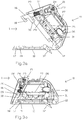
- Fig. 1a shows a perspective view of an embodiment of a security device 1 according to the invention, which is attached to an object 2, for example a sales box, spanned by two intersecting bands 3.
- the securing device 1 is shown in the closed state and in engagement with the two straps 3.
- the two bands 3 run through the safety device 1 and intersect in this.
- the securing device 1 is held on the surface of the object 2 by the tension of the bands 3.
- Fig. 1b shows a plan view of the securing device 1 and the object 2 spanned by the bands 3 Fig. 1a ).
- Fig. 2a the safety device 1 is off Fig. 1a ) shown in the open state in a perspective view.
- Fig. 2b shows the safety device 1 in the closed state.
- Fig. 3 shows the safety device 1 Fig. 1 alone in a view of the section along the section line AA Fig. 1b ) in the open state ( Fig. 3a ) and when closed ( Fig. 3b ).
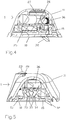
- Fig. 4 shows the securing device alone in a view of the section along the section line BB Fig. 1b ) and Fig. 5 in a view of the section along the section line CC Fig. 1b ) each in the closed state.
- the securing device 1 has a housing comprising a base plate 10 and a cover 11. Cover 11 and base plate 10 are movably connected to one another via a hinge 12. In the open state, the securing device 1 with the base plate 10 can be pushed between the surface of the object 2 and the straps 3 spanning the object 2, so that the straps 3 intersect in the middle of the base plate 10.
- the base plate 10 has two groove-shaped depressions 14 which also intersect to guide the bands 3.
- the lid 11 in the Fig. 2a still in the folded-back state, has cutouts 13 along its edge for the straps 3 running through the securing device 1.
- the cover 11 has a plurality of cylindrical projections 15 on the surface which faces the base plate 10 in the closed state. These projections 15, the function of which will be explained below, are arranged such that they lie in the region of the channel-shaped depressions 14 in the closed state of the securing device 1.
- the cover 11 can be locked with the base plate 10 in the closed state of the securing device 1.
- the locking provided for this purpose comprises a hook-shaped slide 16 which can be moved in the cover 11 between two positions.
- the extended position of the slide 16 shows Fig. 3a ) while the safety device is open, while Fig. 3b ) shows the slide 16 in its inserted position in the closed state of the safety device.
- the slider 16 engages in a recess 17 in the base plate 10 and engages under it with its hook-shaped end 18, the inner edge 19 thereof.
- This engaging occurs when the slider 16 closes the lid 11 starting from its extended position under an oblique angle Angle relative to the base plate 10 is pressed into the lid 11 as soon as it is in Engagement with the recess 17 has come and is present in it.
- a spring 20, which is otherwise arranged between the slide 16 and the cover 11, is also tensioned, which loads the cover 11 in the opening direction or the slide 16 into its extended position and the resistance of which must be overcome when the cover 11 is closed.
- the opening of the lid 11 under the action of the spring 20 is in accordance with the closed state Fig. 3b however, prevented by a magnetic lock 21 provided in the cover 11.
- the lock 21 is of the type known from so-called hard tags.
- a thin pin 22 connected to the slide 16 is inserted into this lock 21 when the slide 16 moves into its inserted position, where it is prevented from moving back by spring-loaded balls.
- Cover 11 and base plate 10 are thereby automatically locked together when the cover 11 is closed in the closed state of the securing device, without further manipulation being necessary for this.
- the balls of the lock 21 must be pulled away from the pin 22 by the force of a magnet to be applied to 23 against the action of a spring 24 acting on them, so that this is free and can be withdrawn from the lock 21.
- the lid 11 jumps open automatically and the slide 16 in its extended position.
- the means for generating the alarm are also essentially arranged in the cover 11. These means comprise a battery 25 (in Fig. 2a ) denotes 25 the battery compartment), electronics (PCB) 26, an acoustic signal transmitter (buzzer) 27, an optical signal transmitter (LED) 28 and a main switch 29.
- the latter is actuated by a pin 30 formed on the slide 16 and closes when the lid is closed 11 and inserted slider 16 the battery circuit.
- the cover 11 is open and the slide 16 is extended, the battery circuit is interrupted by the main switch 29.
- the means for generating an alarm are thereby activated when the safety device is closed and deactivated when the safety device is opened.
- the means for generating the alarm further comprise a mechanical and an optical sensor.
- the mechanical sensor comprises a contact switch 31 in the cover 11 and a pivotable pushbutton 32 in the base plate 10, which interact when the safety device is closed.
- the button 32 is loaded by a spring so that it normally, as in the Figures 3 - 5 shown, protrudes downward over the base plate 10. If, on the other hand, the securing device is of the type Fig. 1 attached to an object 2 and thus with its base plate 10 under a contact pressure caused by the tensioned bands 3 in contact with the object 2, the button 32 is pivoted back by the object 2 into the base plate 10, whereby the contact switch 31 is actuated. The contact switch 31 thereby assumes a switching position from which the electronics 26 infer the presence of the object 2.
- the button 32 swings out of the base plate, the contact switch 31 being actuated and thereby reaching a switching position from which the electronics 26 concludes that there has been no contact with the object and an alarm (acoustically via the buzzer 27 and / or triggered optically via LED 28).
- the contact switch 31 could also have several switching stages, so that only a slight lifting of the security device from the object merely results in a pre-alarm, e.g. a brief flashing of the optical signal generator (LED) 28, generated in the sense of a warning of further manipulation.
- the optical sensor designed as a reflex light barrier is in Fig. 5 recognizable and has a light transmitter 33 and a reflected light receiver 34. It is preferably insensitive to ambient light in that the light transmitter 33 emits infrared light and the reflected light receiver 34 is only sensitive to infrared light.
- the light transmitter 33 When the safety device is closed, the light transmitter 33 emits light at an oblique angle through an opening 35 in the base plate 10. If the safety device in the manner of Fig. 1 is attached to an object 2, part of this light is reflected on the surface of the object 2 and reaches the reflected light receiver 34 through the opening 35. Against direct light from the light transmitter 33 the reflected light receiver 34 shielded. Depending on the nature of the surface in terms of brightness, color and / or gloss, but also depending on the distance to the surface, more or less reflected light will reach the reflected light receiver. In order to take account of the respective circumstances, the electronics first determine the intensity of the light received in each case after the securing device has been attached and closed on an object and store this as a reference value. Then it can react to changes in the received light intensity.
- Such changes are to be expected in particular if the securing device is separated from the object, and a slight lifting of the securing device from the object in the area of the compliance of the object or the tapes may be sufficient.
- Detectable changes can also be caused when a flat object is pushed between the security device and the object, which has slightly different reflection properties, which will usually be the case.
- a flat object in the form of a stiff card between the security device and the object someone could try to remove the security device from the object without the mechanical sensor triggering an alarm by swiveling the button 32 on the flat object when the security device is removed with the flat object is prevented from the base plate 10.
- the optical sensor can also register changes that are produced by moving the security device on an object with a structured surface.
- the securing device should be well fixed on the object with the straps and be as little displaceable as possible.
- the aforementioned cylindrical projections 15 are provided in the cover 11. In the closed state of the securing device, they press on the straps 3, which are guided along the trough-shaped depressions 14 of the base plate 10, and clamp them firmly, so that the securing device 1 cannot be moved along the straps 3.
- the cylindrical projections 15 can consist, for example, of an elastic material.
- the base plate 10 can also be provided with a rubber coating on the side facing the object 2.
- an alarm is only triggered if the displacement exceeds a certain size in each case.
- a light sensor can be used that is sensitive to ambient light.
- the light sensor could e.g. simply react to the difference in brightness that results when the safety device is lifted off the object.
- an electrical resonant circuit consisting of a coil and a capacitor is also present in the cover 11 of the present embodiment, which can be excited and detected by an electronic goods security system, such as is installed in many retail stores.
- the coil has a ferrite core, which is designated by 36.
- the lid 11 springs open under the action of the spring 20 when unlocking and the slide 16 into its extended position, the battery circuit being interrupted by the main switch 29.
- the safety device can then be removed from object 2 without an alarm being triggered.
- the security device according to the invention is designed with regard to the stability of its parts in such a way that it resists attempts to break it open by force to a certain degree.
- the engagement of the hook-shaped end 18 on the slide 16 with the edge 19 is preferably provided. It can be provided, for example, that the hook-shaped end 18 slides over the edge 19 or breaks off the slide 16.
- the slide 16 remains in its inserted position in the cover 11 and with it the pin 30, so that the main switch 29 also remains in its position closing the battery circuit. This means that the means for generating alarms remain active. If the cover 11 is opened after such a violent breaking open, its distance to the object changes, which is detected by both the mechanical and the optical sensor, which then trigger an alarm.
- Fig. 6 shows an extension of the inventive safety device of Fig. 1 around a cable 50, with which this can be connected to yet another object in order to additionally secure this, if necessary.
- the safety device from Fig. 7 there is a two-wire cable 50, one end of which is provided with a plug 51 and is inserted with this plug 51 in the cover 11 of the housing into a plug-in base 52 provided there.
- said cable end with the plug connection consisting of plug 51 and plug base 52 is not accessible from the outside.
- the plug connection cannot be released in the closed state.
- the cable end in the cover 11 is also secured with several baffles to prevent it being pulled out in the closed state.
- the cable 50 protrudes from the housing through one of the cutouts 13 and is provided with a plurality of spiral windings 53, so that its length can be flexibly adapted to the respective distance from the other object.
- the cable 50 is provided with means for attachment to another object.
- Fig. 6 shows a first embodiment of such means in the form of a further, substantially smaller housing 54.
- a mechanical sensor which can detect contact with another object through the further housing 54 and react to loss of contact with the further object.
- This mechanical sensor can in turn be a contact switch with a button 55, which is loaded by a spring such that it normally protrudes slightly beyond the housing 54 on one side.
- the housing 54 is simply attached to a further object such as with an adhesive strip (not shown), in particular one of the type already described, with the side mentioned for example in Fig. 6 Object 60 shown glued, so that the button 55 is pushed back into the housing 54.
- the contact switch closes a circuit via the cable 50 and the plug connection 51, 52, which is connected to the above-described means for generating the alarm in the cover 11 of the safety device. If there is a loss of contact between the further housing and the further object, these means in the cover 11, when activated, generate an alarm of the type also described above.
- a suitable surface for being able to glue the housing 54 as described can be found on most objects find, which accommodates the fact that the housing 54 can be made relatively small, for example only 1 - 4 cm in length and / or width.
- the embodiment according to comes without adhesive strips for attachment to another object Fig. 7 out.
- the further object must have an opening or the like.
- An eyelet 56 is formed in FIG. 8 at the free end of the cable 50.
- the two wires of the cable 50 are electrically connected to one another in a sleeve 57 closing the eyelet 56.
- the cable 50 thereby in turn forms a closed circuit which is monitored for continuity by the alarm means in the cover 11.
- Cable 50 is connected to another object such as object 61 in Fig. 7 connected by its end provided with the plug 51 being passed through a suitable opening 62 in the object 61, subsequently being pushed through the eyelet 56 to form a closed loop 58 and finally being inserted into the plug base 52 in the cover 11 of the housing.
- An alarm is generated here by the alarm means in the cover 11 when the cable 50 is cut, for example, to remove the further object.
Claims (11)
- Dispositif de sécurisation pour des objets (2) qui sont empêchés d'être ouverts par deux bandes (3) tendues autour de ceux-ci et se croisant, le dispositif de sécurisation (1) possédant un boîtier ayant une plaque de base (10) et un couvercle (11) ainsi que des moyens pour générer une alarme en cas d'éloignement non autorisé du dispositif de sécurisation (1) de l'objet (2), le dispositif de sécurisation (1) possédant un état ouvert et un état fermé, à l'état fermé, la plaque de base (10) et le couvercle (11) pouvant être verrouillés l'un à l'autre au moyen d'un verrouillage, la plaque de base (10) à l'état ouvert pouvant être insérée entre les bandes (3) qui se croisent et l'objet (2), la plaque de base (10) et le couvercle (11), à l'état fermé, pouvant être verrouillés, au moyen du verrouillage, en engageant les bandes (3), les deux bandes, lorsque le dispositif de sécurisation (1) engage les deux bandes et est verrouillé dans l'état fermé, s'étendant à travers le dispositif de sécurisation (1) et se croisant dans celui-ci, le dispositif de sécurisation (1), lorsqu'il engage les deux bandes et est verrouillé dans l'état fermé, étant maintenu sur la surface de l'objet (2) par la tension des bandes (3), le verrouillage étant activé par la fermeture du dispositif de sécurisation et les moyens pour générer une alarme comportant un circuit de résonance détectable par un système électronique de surveillance de marchandises, caractérisé en ce que les moyens pour générer une alarme comportent un capteur mécanique (31, 32) muni d'un commutateur de contact (31) qui, à l'état fermé, peut détecter un contact avec l'objet (2) à travers la plaque de base (10) et peut réagir à une perte de contact avec l'objet (2), en ce que les moyens pour générer une alarme sont activés lors de la fermeture du dispositif de sécurisation, en ce que les moyens pour générer une alarme sont désactivés lors de l'ouverture du dispositif de sécurisation après une libération du verrouillage, en ce que le verrouillage comporte un curseur (16) et une serrure magnétique (21) et en ce que la fermeture du dispositif de sécurisation comporte un mouvement du curseur (16) d'une position sortie dans une position insérée.
- Dispositif de sécurisation selon la revendication 1, caractérisé en ce que la plaque de base (10) et le couvercle (11) sont reliés avec mobilité l'un à l'autre par le biais d'une charnière (12).
- Dispositif de sécurisation selon l'une des revendications 1 et 2, caractérisé en ce que les moyens pour générer une alarme comportent un capteur optique (33, 34) qui, à l'état fermé, émet de la lumière à travers la plaque de base (10), peut détecter des réflexions de cette lumière par l'objet (2) à travers la plaque de base (10) et peut réagir aux modifications de ces réflexions.
- Dispositif de sécurisation selon l'une des revendications 1 à 3, caractérisé en ce que le capteur optique est une barrière photoélectrique à réflexion (33, 34) ou un capteur d'image et est de préférence insensible à la lumière ambiante, la lumière émise par lui étant en outre de préférence de la lumière infrarouge.
- Dispositif de sécurisation selon l'une des revendications 1 à 4, caractérisé en ce que le verrouillage peut également être libéré mécaniquement avec une clé.
- Dispositif de sécurisation selon l'une des revendications 1 à 5, caractérisé en ce que les moyens pour générer une alarme peuvent être désactivés par commande à distance ou au moyen d'une plaque de désactivation.
- Dispositif de sécurisation selon l'une des revendications 1 à 6, caractérisé en ce que les moyens pour générer une alarme sont configurés pour générer une alarme à plusieurs niveaux en ce qui concerne son intensité et/ou sa durée.
- Dispositif de sécurisation selon l'une des revendications 1 à 7, caractérisé en ce que la plaque de base (10) possède des empreintes (14) en forme de gouttière et/ou le couvercle (11) possède plusieurs cavités (13) dans lesquelles peuvent être placées les bandes (3).
- Dispositif de sécurisation selon l'une des revendications 1 à 8, caractérisé en ce qu'il (1) possède des moyens (15) contre un glissement de la plaque de base (10) sur l'objet (2) à sécuriser.
- Dispositif de sécurisation selon l'une des revendications 1 à 9, caractérisé en ce qu'auprès de la serrure magnétique (21), une broche (22) mince reliée au curseur (16) est introduite dans cette serrure (21) lors du mouvement du curseur (16) de sa position sortie dans sa position insérée, où son mouvement de recul est empêché par des billes montées sur ressort et avec laquelle, pour libérer le verrouillage, les billes de la serrure (21) sont tirées à l'écart de la broche (22) par la force d'un aimant agissant contre l'effet d'un ressort (24) qui agit sur elles.
- Dispositif de sécurisation selon l'une des revendications 1 à 10, caractérisé en ce que les moyens pour générer une alarme génèrent une alarme lorsque le circuit de résonance est excité par un système électronique de surveillance de marchandises.
Applications Claiming Priority (4)
| Application Number | Priority Date | Filing Date | Title |
|---|---|---|---|
| CH00902/10A CH703299A1 (de) | 2010-06-07 | 2010-06-07 | Sicherungsvorrichtung für Objekte. |
| PCT/CH2011/000134 WO2011153651A1 (fr) | 2010-06-07 | 2011-06-07 | Dispositif d'immobilisation pour objets |
| EP15158287.1A EP2905759B1 (fr) | 2010-06-07 | 2011-06-07 | Dispositif d'immobilisation pour objets |
| EP11725859.0A EP2577631B1 (fr) | 2010-06-07 | 2011-06-07 | Dispositif d'immobilisation pour objets |
Related Parent Applications (2)
| Application Number | Title | Priority Date | Filing Date |
|---|---|---|---|
| EP11725859.0A Division EP2577631B1 (fr) | 2010-06-07 | 2011-06-07 | Dispositif d'immobilisation pour objets |
| EP15158287.1A Division EP2905759B1 (fr) | 2010-06-07 | 2011-06-07 | Dispositif d'immobilisation pour objets |
Publications (2)
| Publication Number | Publication Date |
|---|---|
| EP3206197A1 EP3206197A1 (fr) | 2017-08-16 |
| EP3206197B1 true EP3206197B1 (fr) | 2020-04-08 |
Family
ID=43827221
Family Applications (3)
| Application Number | Title | Priority Date | Filing Date |
|---|---|---|---|
| EP17162106.3A Active EP3206197B1 (fr) | 2010-06-07 | 2011-06-07 | Dispositif d'immobilisation pour objets |
| EP11725859.0A Active EP2577631B1 (fr) | 2010-06-07 | 2011-06-07 | Dispositif d'immobilisation pour objets |
| EP15158287.1A Active EP2905759B1 (fr) | 2010-06-07 | 2011-06-07 | Dispositif d'immobilisation pour objets |
Family Applications After (2)
| Application Number | Title | Priority Date | Filing Date |
|---|---|---|---|
| EP11725859.0A Active EP2577631B1 (fr) | 2010-06-07 | 2011-06-07 | Dispositif d'immobilisation pour objets |
| EP15158287.1A Active EP2905759B1 (fr) | 2010-06-07 | 2011-06-07 | Dispositif d'immobilisation pour objets |
Country Status (4)
| Country | Link |
|---|---|
| US (2) | US9524626B2 (fr) |
| EP (3) | EP3206197B1 (fr) |
| CH (1) | CH703299A1 (fr) |
| WO (1) | WO2011153651A1 (fr) |
Families Citing this family (32)
| Publication number | Priority date | Publication date | Assignee | Title |
|---|---|---|---|---|
| US9404291B1 (en) * | 2015-03-04 | 2016-08-02 | Checkpoint Systems, Inc. | Device and method for an alarming strap tag |
| CH703299A1 (de) | 2010-06-07 | 2011-12-15 | Pataco Ag Ind Und Unterhaltungselektronik | Sicherungsvorrichtung für Objekte. |
| US9103142B2 (en) | 2011-02-24 | 2015-08-11 | Invue Security Products Inc. | Merchandise display security tether including releasable adhesive |
| PL2920015T3 (pl) | 2012-10-17 | 2020-10-05 | Hutchinson S.A. | Moduł tłumienia ognia, system modułowy zawierający taki moduł, oraz sposób instalowania systemu modułowego |
| US20160005279A1 (en) * | 2013-02-20 | 2016-01-07 | Giovanni Salvo | Device and package for retail theft prevention |
| WO2015054192A1 (fr) | 2013-10-08 | 2015-04-16 | Invue Security Products, Inc. | Capteur à détachement rapide pour présentoir de marchandise |
| US10180017B2 (en) * | 2015-06-08 | 2019-01-15 | Southern Imperial Llc | Security device with reusable base member |
| US20170175426A1 (en) * | 2015-12-18 | 2017-06-22 | Checkpoint Systems, Inc. | Anti-impact locking feature |
| USD899218S1 (en) * | 2016-04-10 | 2020-10-20 | Delta Lock Company, LLC | Locking device |
| GB2549699B (en) * | 2016-04-18 | 2021-07-07 | Sekura Global Ip Llp | Security tag |
| CH712486A1 (de) | 2016-05-24 | 2017-11-30 | Pataco Ag | Klebeetikett, Sicherungskabel, Sicherungsanordnung und Verfahren zum Sichern von Objekten. |
| US9934665B1 (en) | 2016-09-16 | 2018-04-03 | Ningsheng Zhang | Box edge security device |
| US9965933B1 (en) | 2017-03-08 | 2018-05-08 | Checkpoint Systems, Inc. | Product strap detection apparatus and method |
| US20180340357A1 (en) | 2017-05-25 | 2018-11-29 | Invue Security Products Inc. | Package wrap |
| US11619073B2 (en) * | 2017-07-28 | 2023-04-04 | Checkpoint Systems, Inc. | Locking sled security device |
| CN107444771A (zh) * | 2017-08-04 | 2017-12-08 | 思创医惠科技股份有限公司 | 一种包装盒保护装置及其报警方法 |
| JP6975973B2 (ja) * | 2018-01-22 | 2021-12-01 | エム・ケー・パビック株式会社 | 盗難防止装置及びアタッチメント |
| US11164433B2 (en) * | 2018-02-01 | 2021-11-02 | Edge Security Products, Llc | Box edge security device |
| AT16444U1 (de) * | 2018-04-26 | 2019-10-15 | Veder Waterbox Gmbh | Sicherheitszustellvorrichtung und -system zum Schutz einer Ware |
| WO2019204851A1 (fr) * | 2018-04-26 | 2019-10-31 | Veder Waterbox Gmbh | Dispositif de distribution, système de distribution et procédé de distribution d'envois |
| US11908307B2 (en) | 2018-06-07 | 2024-02-20 | William J. Hoofe, IV | Security system |
| US11322005B2 (en) * | 2018-06-10 | 2022-05-03 | Hangzhou Timing Security Technologies Co., Ltd. | Portions of a security device system; methods of making and using them |
| CN110006553B (zh) * | 2019-04-29 | 2024-01-16 | 国家电网有限公司 | 一种无源无线测温装置 |
| GB2591269B (en) * | 2020-01-23 | 2023-10-18 | Sekura Global Ip Llp | Security tag |
| US11429830B2 (en) | 2020-03-05 | 2022-08-30 | Fasteners For Retail, Inc. | Security tag holder and assembly for use with package having curved surfaces |
| USD956607S1 (en) | 2020-04-16 | 2022-07-05 | Fasteners For Retail, Inc. | Security tag holder |
| US20210355715A1 (en) * | 2020-05-18 | 2021-11-18 | Fasteners For Retail, Inc. | Security tag holder |
| US20230386312A1 (en) | 2020-10-22 | 2023-11-30 | Pataco Ag | Security bag |
| USD988835S1 (en) | 2021-05-10 | 2023-06-13 | Innovation Lock, Llc | Ratchet locking device |
| US11879269B2 (en) | 2021-05-10 | 2024-01-23 | Innovation Lock, Llc | Ratchet lock assemblies |
| US20220398884A1 (en) * | 2021-06-09 | 2022-12-15 | Ashten Gilliard | Retail Point of Sale Security System |
| CN116101155B (zh) * | 2023-03-21 | 2023-09-12 | 张家港欣迈克五金工具有限公司 | 一种夜间行车用货物固定装置 |
Family Cites Families (37)
| Publication number | Priority date | Publication date | Assignee | Title |
|---|---|---|---|---|
| US4620182A (en) * | 1985-01-10 | 1986-10-28 | Check Mate Systems, Inc. | Security apparatus for retail goods |
| US5349834A (en) | 1992-03-17 | 1994-09-27 | Tortoise Products, Inc. | Adhesively mounted security system |
| EP0642442A1 (fr) * | 1992-06-02 | 1995-03-15 | Minnesota Mining And Manufacturing Company | Systeme distributeur a l'unite pour bande adhesive a decollement par etirement variable |
| DE4222849C2 (de) * | 1992-07-11 | 2000-02-10 | Beiersdorf Ag | Verwendung eines Streifens einer Klebefolie für wiederlösbare Verklebung |
| US5910768A (en) * | 1995-04-04 | 1999-06-08 | Ott; Reinhold | Anti-theft device |
| US5627520A (en) * | 1995-07-10 | 1997-05-06 | Protell Systems International, Inc. | Tamper detect monitoring device |
| US5699591A (en) | 1996-05-29 | 1997-12-23 | Kane; Roger | Security anchor |
| US5709110A (en) | 1996-10-07 | 1998-01-20 | Greenfield; Jack | Security system for a lap-top computer |
| US5886633A (en) * | 1998-06-29 | 1999-03-23 | I.S.P.A. Woodworking Limited | Selectively disconnectable sensor switch for an alarm |
| EP0978812B1 (fr) * | 1998-08-03 | 2006-04-12 | Hi-G-Tek Ltd | Sceau autoverrouillable |
| US6105922A (en) | 1999-08-09 | 2000-08-22 | Derman; Jay S. | Support device for attaching wire cable or a padlock shackle to portable equipment |
| US6641910B1 (en) * | 1999-08-24 | 2003-11-04 | 3M Innovative Properties Company | Stretch releasing adhesive tape with segmented release liner |
| US6578394B2 (en) * | 2001-09-06 | 2003-06-17 | Hewlett-Packard Development Company | Portable computer security device |
| US6811126B2 (en) * | 2001-09-13 | 2004-11-02 | 3M Innovative Properties Company | Stretch releasing adhesive tape article with flexible cover |
| DE10251133B3 (de) * | 2002-10-31 | 2004-07-29 | Gerd Reime | Einrichtung zur Steuerung einer Beleuchtung, insbesondere für Fahrzeuginnenräume sowie Verfahren zu ihrer Steuerung |
| US7501937B2 (en) * | 2003-08-27 | 2009-03-10 | Omega Patents, L.L.C. | Vehicle security device including pre-warn indicator and related methods |
| US7168275B2 (en) * | 2004-12-28 | 2007-01-30 | Alpha Security Products, Inc. | Cable wrap security device |
| WO2007027345A2 (fr) * | 2005-07-27 | 2007-03-08 | Autronic Plastics, Inc. | Dispositifs antivol de surete et systeme de detection perimetrique |
| US20070171061A1 (en) * | 2006-01-13 | 2007-07-26 | Alpha Security Products, Inc. | Theft deterrent device with dual sensor assembly |
| JP5043340B2 (ja) * | 2006-02-01 | 2012-10-10 | スリーエム イノベイティブ プロパティズ カンパニー | 物品取り付けキット |
| US8081075B2 (en) * | 2006-03-31 | 2011-12-20 | Checkpoint Systems, Inc. | Tether cord and sensor alarms |
| US20080246656A1 (en) * | 2006-04-25 | 2008-10-09 | Ghazarian Ohanes D | Automatic GPS tracking system with passive battery circuitry |
| CH698863B1 (de) * | 2006-07-19 | 2009-11-30 | Pataco Ag Ind Und Unterhaltung | Sicherungsvorrichtung |
| US20080018066A1 (en) * | 2006-07-20 | 2008-01-24 | Kehau Pickford | Footwear contact indication system |
| US7522048B2 (en) * | 2007-01-12 | 2009-04-21 | Checkpoint Systems, Inc. | Banding clip alarm |
| US8122744B2 (en) * | 2007-03-28 | 2012-02-28 | Checkpoint Systems, Inc. | Cable wrap security device |
| CA2690131C (fr) * | 2007-06-08 | 2017-07-04 | Chris Chattaway | Procede et systeme pour determiner l'alteration d'une etiquette rfid |
| US8650097B2 (en) * | 2007-12-03 | 2014-02-11 | Yu Yung Choi | System and method for streamlined registration of products over a communication network and for verification and management of information related thereto |
| US8274391B2 (en) * | 2008-02-22 | 2012-09-25 | Xiao Hui Yang | EAS tag using tape with conductive element |
| US8305219B2 (en) * | 2008-02-22 | 2012-11-06 | Xiao Hui Yang | EAS tag using tape with conductive element |
| US20090235428A1 (en) * | 2008-03-20 | 2009-09-24 | Horne Iii Franklin Stebin | Item Wrapping Assistance Device |
| US20100147041A1 (en) * | 2008-12-16 | 2010-06-17 | Sandisk Il Ltd. | Tethering arrangement for portable electronic devices |
| US8514070B2 (en) * | 2010-04-07 | 2013-08-20 | Securealert, Inc. | Tracking device incorporating enhanced security mounting strap |
| CH703299A1 (de) * | 2010-06-07 | 2011-12-15 | Pataco Ag Ind Und Unterhaltungselektronik | Sicherungsvorrichtung für Objekte. |
| US9103142B2 (en) | 2011-02-24 | 2015-08-11 | Invue Security Products Inc. | Merchandise display security tether including releasable adhesive |
| US8541745B2 (en) * | 2011-11-16 | 2013-09-24 | Motorola Mobility Llc | Methods and devices for clothing detection about a wearable electronic device |
| ES2566604T3 (es) * | 2012-04-03 | 2016-04-14 | Hartmut Schmitz | Dispositivo de cierre para una eslinga de cable, dispositivo de seguridad, dispositivo de alta presión y método para montar el dispositivo de seguridad |
-
2010
- 2010-06-07 CH CH00902/10A patent/CH703299A1/de not_active Application Discontinuation
-
2011
- 2011-06-07 WO PCT/CH2011/000134 patent/WO2011153651A1/fr active Application Filing
- 2011-06-07 EP EP17162106.3A patent/EP3206197B1/fr active Active
- 2011-06-07 EP EP11725859.0A patent/EP2577631B1/fr active Active
- 2011-06-07 EP EP15158287.1A patent/EP2905759B1/fr active Active
- 2011-06-07 US US13/702,891 patent/US9524626B2/en active Active
-
2016
- 2016-11-11 US US15/349,721 patent/US10134248B2/en active Active
Non-Patent Citations (1)
| Title |
|---|
| None * |
Also Published As
| Publication number | Publication date |
|---|---|
| EP2905759A1 (fr) | 2015-08-12 |
| US20170323536A1 (en) | 2017-11-09 |
| WO2011153651A1 (fr) | 2011-12-15 |
| EP2577631B1 (fr) | 2015-03-11 |
| EP2577631A1 (fr) | 2013-04-10 |
| CH703299A1 (de) | 2011-12-15 |
| US20130169440A1 (en) | 2013-07-04 |
| EP3206197A1 (fr) | 2017-08-16 |
| EP2905759B1 (fr) | 2017-03-22 |
| US9524626B2 (en) | 2016-12-20 |
| US10134248B2 (en) | 2018-11-20 |
Similar Documents
| Publication | Publication Date | Title |
|---|---|---|
| EP3206197B1 (fr) | Dispositif d'immobilisation pour objets | |
| DE60204869T2 (de) | Diebstahlschutz, insbesondere für verkaufsstellenauslagen | |
| DE102008009491B4 (de) | Vorrichtung zur Sicherung von Waren | |
| DE602005005091T2 (de) | Sicherheitsvorrichtung für eine Flasche | |
| CH684134A5 (de) | An einen Gegenstand anbringbarer Sicherungsanhänger zur Signalisierung eines versuchten Diebstahls. | |
| DE19713110A1 (de) | Tragbare Antidiebstahl-Überwachungsvorrichtung | |
| DE112008002047T5 (de) | Diebstahlschutzvorrichtung | |
| DE102009049738A1 (de) | Vorrichtung zur Sicherung von Gegenständen | |
| DD294584A5 (de) | Erkennungsmarke fuer ein system zur verhinderung von ladendiebstaehlen | |
| DE112004000006T5 (de) | Sicherheitsbehälter mit verbundenen ersten und zweiten Sicherheitseinrichtungen | |
| EP2772890B1 (fr) | Dispositif d'alarme | |
| DE202018100247U1 (de) | Warensicherungsvorrichtung mit umhülltem Eingriffsstift | |
| WO2008009148A1 (fr) | Dispositif de sécurité | |
| WO2008144952A1 (fr) | Contenant destiné à sécuriser un objet contre le vol et outil et procédé destinés à ouvrir le contenant | |
| WO2021214458A1 (fr) | Dispositif de sécurité | |
| DE102004041602A1 (de) | Warensicherungseinrichtung mit Farbsicherung | |
| DE3916615C2 (fr) | ||
| DE2248443A1 (de) | Signalgebende vorrichtung zur sicherung von gegenstaenden gegen diebstahl | |
| DE202007013449U1 (de) | Warensicherungsvorrichtung zur Sicherung von Waren und Zubehörteilen gegen Diebstahl | |
| EP0819290B1 (fr) | Dispositif antivol | |
| DE102004027089A1 (de) | Kleinvolumige Warensicherungseinrichtung zur Anbringung an Waren | |
| DE19512567C1 (de) | Diebstahlsicherungsvorrichtung | |
| DE4418542A1 (de) | Diebstahlsicherungselement | |
| DE102015014920B3 (de) | Teilbare Vorrichtung zum Sichern zweier Bänder | |
| WO2005041153A2 (fr) | Dispositif de volume reduit pour securiser des marchandises, a placer sur des marchandises |
Legal Events
| Date | Code | Title | Description |
|---|---|---|---|
| PUAI | Public reference made under article 153(3) epc to a published international application that has entered the european phase |
Free format text: ORIGINAL CODE: 0009012 |
|
| STAA | Information on the status of an ep patent application or granted ep patent |
Free format text: STATUS: THE APPLICATION HAS BEEN PUBLISHED |
|
| AC | Divisional application: reference to earlier application |
Ref document number: 2577631 Country of ref document: EP Kind code of ref document: P Ref document number: 2905759 Country of ref document: EP Kind code of ref document: P |
|
| AK | Designated contracting states |
Kind code of ref document: A1 Designated state(s): AL AT BE BG CH CY CZ DE DK EE ES FI FR GB GR HR HU IE IS IT LI LT LU LV MC MK MT NL NO PL PT RO RS SE SI SK SM TR |
|
| AX | Request for extension of the european patent |
Extension state: BA ME |
|
| STAA | Information on the status of an ep patent application or granted ep patent |
Free format text: STATUS: REQUEST FOR EXAMINATION WAS MADE |
|
| 17P | Request for examination filed |
Effective date: 20180216 |
|
| RBV | Designated contracting states (corrected) |
Designated state(s): AL AT BE BG CH CY CZ DE DK EE ES FI FR GB GR HR HU IE IS IT LI LT LU LV MC MK MT NL NO PL PT RO RS SE SI SK SM TR |
|
| GRAP | Despatch of communication of intention to grant a patent |
Free format text: ORIGINAL CODE: EPIDOSNIGR1 |
|
| STAA | Information on the status of an ep patent application or granted ep patent |
Free format text: STATUS: GRANT OF PATENT IS INTENDED |
|
| INTG | Intention to grant announced |
Effective date: 20191108 |
|
| GRAS | Grant fee paid |
Free format text: ORIGINAL CODE: EPIDOSNIGR3 |
|
| GRAA | (expected) grant |
Free format text: ORIGINAL CODE: 0009210 |
|
| STAA | Information on the status of an ep patent application or granted ep patent |
Free format text: STATUS: THE PATENT HAS BEEN GRANTED |
|
| AC | Divisional application: reference to earlier application |
Ref document number: 2905759 Country of ref document: EP Kind code of ref document: P Ref document number: 2577631 Country of ref document: EP Kind code of ref document: P |
|
| AK | Designated contracting states |
Kind code of ref document: B1 Designated state(s): AL AT BE BG CH CY CZ DE DK EE ES FI FR GB GR HR HU IE IS IT LI LT LU LV MC MK MT NL NO PL PT RO RS SE SI SK SM TR |
|
| REG | Reference to a national code |
Ref country code: CH Ref legal event code: EP Ref country code: AT Ref legal event code: REF Ref document number: 1255409 Country of ref document: AT Kind code of ref document: T Effective date: 20200415 |
|
| REG | Reference to a national code |
Ref country code: DE Ref legal event code: R096 Ref document number: 502011016609 Country of ref document: DE |
|
| REG | Reference to a national code |
Ref country code: IE Ref legal event code: FG4D Free format text: LANGUAGE OF EP DOCUMENT: GERMAN |
|
| REG | Reference to a national code |
Ref country code: CH Ref legal event code: NV Representative=s name: RENTSCH PARTNER AG, CH |
|
| REG | Reference to a national code |
Ref country code: NL Ref legal event code: MP Effective date: 20200408 |
|
| REG | Reference to a national code |
Ref country code: LT Ref legal event code: MG4D |
|
| PG25 | Lapsed in a contracting state [announced via postgrant information from national office to epo] |
Ref country code: IS Free format text: LAPSE BECAUSE OF FAILURE TO SUBMIT A TRANSLATION OF THE DESCRIPTION OR TO PAY THE FEE WITHIN THE PRESCRIBED TIME-LIMIT Effective date: 20200808 Ref country code: SE Free format text: LAPSE BECAUSE OF FAILURE TO SUBMIT A TRANSLATION OF THE DESCRIPTION OR TO PAY THE FEE WITHIN THE PRESCRIBED TIME-LIMIT Effective date: 20200408 Ref country code: GR Free format text: LAPSE BECAUSE OF FAILURE TO SUBMIT A TRANSLATION OF THE DESCRIPTION OR TO PAY THE FEE WITHIN THE PRESCRIBED TIME-LIMIT Effective date: 20200709 Ref country code: NO Free format text: LAPSE BECAUSE OF FAILURE TO SUBMIT A TRANSLATION OF THE DESCRIPTION OR TO PAY THE FEE WITHIN THE PRESCRIBED TIME-LIMIT Effective date: 20200708 Ref country code: FI Free format text: LAPSE BECAUSE OF FAILURE TO SUBMIT A TRANSLATION OF THE DESCRIPTION OR TO PAY THE FEE WITHIN THE PRESCRIBED TIME-LIMIT Effective date: 20200408 Ref country code: PT Free format text: LAPSE BECAUSE OF FAILURE TO SUBMIT A TRANSLATION OF THE DESCRIPTION OR TO PAY THE FEE WITHIN THE PRESCRIBED TIME-LIMIT Effective date: 20200817 Ref country code: LT Free format text: LAPSE BECAUSE OF FAILURE TO SUBMIT A TRANSLATION OF THE DESCRIPTION OR TO PAY THE FEE WITHIN THE PRESCRIBED TIME-LIMIT Effective date: 20200408 Ref country code: NL Free format text: LAPSE BECAUSE OF FAILURE TO SUBMIT A TRANSLATION OF THE DESCRIPTION OR TO PAY THE FEE WITHIN THE PRESCRIBED TIME-LIMIT Effective date: 20200408 |
|
| PG25 | Lapsed in a contracting state [announced via postgrant information from national office to epo] |
Ref country code: LV Free format text: LAPSE BECAUSE OF FAILURE TO SUBMIT A TRANSLATION OF THE DESCRIPTION OR TO PAY THE FEE WITHIN THE PRESCRIBED TIME-LIMIT Effective date: 20200408 Ref country code: RS Free format text: LAPSE BECAUSE OF FAILURE TO SUBMIT A TRANSLATION OF THE DESCRIPTION OR TO PAY THE FEE WITHIN THE PRESCRIBED TIME-LIMIT Effective date: 20200408 Ref country code: HR Free format text: LAPSE BECAUSE OF FAILURE TO SUBMIT A TRANSLATION OF THE DESCRIPTION OR TO PAY THE FEE WITHIN THE PRESCRIBED TIME-LIMIT Effective date: 20200408 Ref country code: BG Free format text: LAPSE BECAUSE OF FAILURE TO SUBMIT A TRANSLATION OF THE DESCRIPTION OR TO PAY THE FEE WITHIN THE PRESCRIBED TIME-LIMIT Effective date: 20200708 |
|
| PG25 | Lapsed in a contracting state [announced via postgrant information from national office to epo] |
Ref country code: AL Free format text: LAPSE BECAUSE OF FAILURE TO SUBMIT A TRANSLATION OF THE DESCRIPTION OR TO PAY THE FEE WITHIN THE PRESCRIBED TIME-LIMIT Effective date: 20200408 |
|
| REG | Reference to a national code |
Ref country code: DE Ref legal event code: R097 Ref document number: 502011016609 Country of ref document: DE |
|
| PG25 | Lapsed in a contracting state [announced via postgrant information from national office to epo] |
Ref country code: SM Free format text: LAPSE BECAUSE OF FAILURE TO SUBMIT A TRANSLATION OF THE DESCRIPTION OR TO PAY THE FEE WITHIN THE PRESCRIBED TIME-LIMIT Effective date: 20200408 Ref country code: IT Free format text: LAPSE BECAUSE OF FAILURE TO SUBMIT A TRANSLATION OF THE DESCRIPTION OR TO PAY THE FEE WITHIN THE PRESCRIBED TIME-LIMIT Effective date: 20200408 Ref country code: EE Free format text: LAPSE BECAUSE OF FAILURE TO SUBMIT A TRANSLATION OF THE DESCRIPTION OR TO PAY THE FEE WITHIN THE PRESCRIBED TIME-LIMIT Effective date: 20200408 Ref country code: DK Free format text: LAPSE BECAUSE OF FAILURE TO SUBMIT A TRANSLATION OF THE DESCRIPTION OR TO PAY THE FEE WITHIN THE PRESCRIBED TIME-LIMIT Effective date: 20200408 Ref country code: MC Free format text: LAPSE BECAUSE OF FAILURE TO SUBMIT A TRANSLATION OF THE DESCRIPTION OR TO PAY THE FEE WITHIN THE PRESCRIBED TIME-LIMIT Effective date: 20200408 Ref country code: ES Free format text: LAPSE BECAUSE OF FAILURE TO SUBMIT A TRANSLATION OF THE DESCRIPTION OR TO PAY THE FEE WITHIN THE PRESCRIBED TIME-LIMIT Effective date: 20200408 Ref country code: CZ Free format text: LAPSE BECAUSE OF FAILURE TO SUBMIT A TRANSLATION OF THE DESCRIPTION OR TO PAY THE FEE WITHIN THE PRESCRIBED TIME-LIMIT Effective date: 20200408 Ref country code: RO Free format text: LAPSE BECAUSE OF FAILURE TO SUBMIT A TRANSLATION OF THE DESCRIPTION OR TO PAY THE FEE WITHIN THE PRESCRIBED TIME-LIMIT Effective date: 20200408 |
|
| PLBE | No opposition filed within time limit |
Free format text: ORIGINAL CODE: 0009261 |
|
| STAA | Information on the status of an ep patent application or granted ep patent |
Free format text: STATUS: NO OPPOSITION FILED WITHIN TIME LIMIT |
|
| PG25 | Lapsed in a contracting state [announced via postgrant information from national office to epo] |
Ref country code: SK Free format text: LAPSE BECAUSE OF FAILURE TO SUBMIT A TRANSLATION OF THE DESCRIPTION OR TO PAY THE FEE WITHIN THE PRESCRIBED TIME-LIMIT Effective date: 20200408 Ref country code: PL Free format text: LAPSE BECAUSE OF FAILURE TO SUBMIT A TRANSLATION OF THE DESCRIPTION OR TO PAY THE FEE WITHIN THE PRESCRIBED TIME-LIMIT Effective date: 20200408 |
|
| 26N | No opposition filed |
Effective date: 20210112 |
|
| PG25 | Lapsed in a contracting state [announced via postgrant information from national office to epo] |
Ref country code: LU Free format text: LAPSE BECAUSE OF NON-PAYMENT OF DUE FEES Effective date: 20200607 |
|
| PG25 | Lapsed in a contracting state [announced via postgrant information from national office to epo] |
Ref country code: IE Free format text: LAPSE BECAUSE OF NON-PAYMENT OF DUE FEES Effective date: 20200607 |
|
| PG25 | Lapsed in a contracting state [announced via postgrant information from national office to epo] |
Ref country code: SI Free format text: LAPSE BECAUSE OF FAILURE TO SUBMIT A TRANSLATION OF THE DESCRIPTION OR TO PAY THE FEE WITHIN THE PRESCRIBED TIME-LIMIT Effective date: 20200408 |
|
| PG25 | Lapsed in a contracting state [announced via postgrant information from national office to epo] |
Ref country code: TR Free format text: LAPSE BECAUSE OF FAILURE TO SUBMIT A TRANSLATION OF THE DESCRIPTION OR TO PAY THE FEE WITHIN THE PRESCRIBED TIME-LIMIT Effective date: 20200408 Ref country code: MT Free format text: LAPSE BECAUSE OF FAILURE TO SUBMIT A TRANSLATION OF THE DESCRIPTION OR TO PAY THE FEE WITHIN THE PRESCRIBED TIME-LIMIT Effective date: 20200408 Ref country code: CY Free format text: LAPSE BECAUSE OF FAILURE TO SUBMIT A TRANSLATION OF THE DESCRIPTION OR TO PAY THE FEE WITHIN THE PRESCRIBED TIME-LIMIT Effective date: 20200408 |
|
| PG25 | Lapsed in a contracting state [announced via postgrant information from national office to epo] |
Ref country code: MK Free format text: LAPSE BECAUSE OF FAILURE TO SUBMIT A TRANSLATION OF THE DESCRIPTION OR TO PAY THE FEE WITHIN THE PRESCRIBED TIME-LIMIT Effective date: 20200408 |
|
| P01 | Opt-out of the competence of the unified patent court (upc) registered |
Effective date: 20230512 |
|
| PGFP | Annual fee paid to national office [announced via postgrant information from national office to epo] |
Ref country code: FR Payment date: 20230628 Year of fee payment: 13 Ref country code: DE Payment date: 20230620 Year of fee payment: 13 |
|
| PGFP | Annual fee paid to national office [announced via postgrant information from national office to epo] |
Ref country code: AT Payment date: 20230621 Year of fee payment: 13 |
|
| PGFP | Annual fee paid to national office [announced via postgrant information from national office to epo] |
Ref country code: BE Payment date: 20230620 Year of fee payment: 13 |
|
| PGFP | Annual fee paid to national office [announced via postgrant information from national office to epo] |
Ref country code: GB Payment date: 20230622 Year of fee payment: 13 Ref country code: CH Payment date: 20230702 Year of fee payment: 13 |