EP3206197B1 - Securing device for objects - Google Patents
Securing device for objects Download PDFInfo
- Publication number
- EP3206197B1 EP3206197B1 EP17162106.3A EP17162106A EP3206197B1 EP 3206197 B1 EP3206197 B1 EP 3206197B1 EP 17162106 A EP17162106 A EP 17162106A EP 3206197 B1 EP3206197 B1 EP 3206197B1
- Authority
- EP
- European Patent Office
- Prior art keywords
- security device
- alarm
- baseplate
- generating
- closed state
- Prior art date
- Legal status (The legal status is an assumption and is not a legal conclusion. Google has not performed a legal analysis and makes no representation as to the accuracy of the status listed.)
- Active
Links
Images


Classifications
-
- G—PHYSICS
- G08—SIGNALLING
- G08B—SIGNALLING OR CALLING SYSTEMS; ORDER TELEGRAPHS; ALARM SYSTEMS
- G08B13/00—Burglar, theft or intruder alarms
-
- E—FIXED CONSTRUCTIONS
- E05—LOCKS; KEYS; WINDOW OR DOOR FITTINGS; SAFES
- E05B—LOCKS; ACCESSORIES THEREFOR; HANDCUFFS
- E05B73/00—Devices for locking portable objects against unauthorised removal; Miscellaneous locking devices
- E05B73/0017—Anti-theft devices, e.g. tags or monitors, fixed to articles, e.g. clothes, and to be removed at the check-out of shops
- E05B73/0029—Tags wrapped around the protected product using cables, wires or the like, e.g. with cable retraction for tensioning
-
- G—PHYSICS
- G08—SIGNALLING
- G08B—SIGNALLING OR CALLING SYSTEMS; ORDER TELEGRAPHS; ALARM SYSTEMS
- G08B13/00—Burglar, theft or intruder alarms
- G08B13/22—Electrical actuation
- G08B13/24—Electrical actuation by interference with electromagnetic field distribution
- G08B13/2402—Electronic Article Surveillance [EAS], i.e. systems using tags for detecting removal of a tagged item from a secure area, e.g. tags for detecting shoplifting
- G08B13/2428—Tag details
- G08B13/2434—Tag housing and attachment details
-
- E—FIXED CONSTRUCTIONS
- E05—LOCKS; KEYS; WINDOW OR DOOR FITTINGS; SAFES
- E05B—LOCKS; ACCESSORIES THEREFOR; HANDCUFFS
- E05B73/00—Devices for locking portable objects against unauthorised removal; Miscellaneous locking devices
- E05B73/0017—Anti-theft devices, e.g. tags or monitors, fixed to articles, e.g. clothes, and to be removed at the check-out of shops
Definitions
- the invention relates to a security device for objects that are prevented from being opened by two straps that cross them and intersect each other, according to the preamble of patent claim 1.
- Tags are attached to the goods to be secured, which can be detected by the electronics of the system via antennas usually arranged at the outlet of the shops.
- the tags are e.g. electrical resonant circuits with resonance frequencies in the radio frequency range (a few MHz).
- tags For the security to work, the tags must be connected to the goods to be secured in such a way that unauthorized persons cannot remove them easily and unnoticed. For garments this is e.g. by inserting a needle through the fabric and securing the tip of the needle with a lock that requires special equipment to remove it.
- the day is housed in the needle head (hard tag) or in the lock. Small items can be stored in clear, lockable containers that hold the day inside.
- tags are used in housings that are attached to the packaging with tapes (or cables).
- the tapes are electrically conductive and are monitored for electrical continuity by electronics. If they are cut to remove the security device without authorization, the electronics generate an alarm.
- a mechanism is housed in the housing for winding and tensioning the tapes. Since this must not be voluminous, the adjustment range is of the belts, which limits their use on packaging in a certain size range.
- a security device is proposed for objects of the type mentioned at the beginning, which are strapped with simple, electrically non-conductive bands, as are used as standard in packaging technology.
- the tapes are made of stable plastic and are stretched around the packaging using a tensioning device, their ends being connected to form a closed loop by means of sealing sleeves or by welding. There are no restrictions on the size of the packaging.
- the securing device has two housing shells which can be locked together and in engagement with the straps.
- the device further comprises two cylindrical, rotatably mounted tensioning elements, each provided with a slot for the straps, which are prestressed by tensioning springs. When attaching the security device to the object, the tapes are guided through the slots of the tensioning elements.
- Closing and locking the two housing shells releases the clamping elements and the straps are additionally tensioned. These means for additional tensioning of the straps are coupled with an alarm. If the additional tension is lost, eg due to unauthorized cutting of the straps, the tensioning elements continue to rotate due to the tension springs and trigger an alarm.
- tapes can also be used to prevent the packaging from being opened.
- the content of the packaging is not checked when buying. It is not uncommon then when unpacking at home it turns out that the content does not meet expectations. This can be caused by the packaging being opened during transport, in the warehouse or in the sales shop and the goods contained therein removed and, at best, exchanged for another, but usually inferior product.
- high-quality, expensive goods are often placed in the packaging of cheaper goods, so that only the lower price of the cheaper goods has to be paid at the checkout.
- the invention has for its object to provide a security device of the type mentioned, which can be attached to objects such as larger packaging boxes so that they can not be removed unnoticed by them, which does not require complex mechanics and still ensures adequate protection.
- the means for generating an alarm include a mechanical and possibly an optical sensor.
- the mechanical sensor When closed, the mechanical sensor can detect contact with the object through the base plate and react to loss of contact with the object. It triggers an alarm in particular if the security device is removed from the object without authorization.
- the optical sensor if present, emits light through the base plate when closed, can detect reflections of this light from the object through the base plate and can react to changes in these reflections. The optical sensor can thus also trigger an alarm if the security device is removed from the object without authorization.
- the base plate and the cover can be movably connected to one another via a hinge for easier handling.
- the optical sensor can be a reflex light barrier or an image sensor, which is preferably insensitive to ambient light.
- the light it emits is further preferably infrared light. But it can also be provided that the optical sensor reacts to ambient light, especially when the security device is lifted from the object.
- the means for generating an alarm have a resonant circuit which can be detected by an electronic goods security system.
- the object to be secured can then, together with the security device according to the invention, that is to say without first removing it from the object, not simply removed from an area monitored by an electronic goods security system, such as a retail store.
- an electronic goods security system such as a retail store.
- the electronic goods security system detects the resonant circuit in the security device according to the invention, it issues an alarm.
- the means for generating an alarm of the security device can generate an alarm if the resonant circuit is excited by an electronic goods security system by the electromagnetic alternating field generated by it.
- the lock is activated when and by closing the safety device. It should only be possible to solve it with a special tool, including a magnet opener, such as is used to open a hard tag of the type mentioned at the beginning, and, if necessary, also with a key.
- a magnet opener such as is used to open a hard tag of the type mentioned at the beginning, and, if necessary, also with a key.
- the means for generating an alarm are activated when and by closing the safety device (in the sense of armed). An activation is of course not yet triggered by this activation. However, the means for generating an alarm can be designed so that they signal their activation by a flashing signal and / or an acoustic control tone.
- the means for generating an alarm are deactivated when authorized opening, for which purpose a special magnetic opener or a key must preferably be used. Deactivation could also be provided electronically by remote control or by means of a deactivator plate. In this case, an alarm would also be triggered, for example, if the safety device was provided with one special magnetic opener or key is opened. If the safety device is opened by force, the means for generating an alarm should of course also be deactivated and an alarm triggered.
- the means for generating an alarm can be designed to generate an alarm which is multi-level in terms of its intensity and / or duration. This can be used to trigger a warning pre-alarm when the safety device is lifted slightly from the object and / or when the safety device is only slightly moved on the object. This may be enough to deter the manipulator from further manipulation without causing general turmoil.
- an alarm can only be triggered at a lower than the highest alarm level if only the optical sensor (19) responds. Especially if this is set sensitively, this can already occur when handling the object with authorization.
- the security device is designed such that it can be attached to the object with two straps stretched around the object to be secured. This is achieved in that the base plate can be inserted between the straps and the object in the open state of the securing device and that the base plate and the lid can be locked in engagement with the straps by means of the lock when the securing device is closed.
- the straps can be attached in such a way that the sales box cannot be opened, at least without causing major damage to it.
- the base plate can have channel-shaped depressions and the cover can have a plurality of recesses into which the tapes can be inserted.
- the securing device can have means to prevent the base plate from slipping on the object to be secured, which can be possible when attached with tapes. This can e.g. a rubber layer or the like, which is arranged on the side of the base plate facing the object.
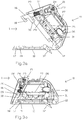
- Fig. 1a shows a perspective view of an embodiment of a security device 1 according to the invention, which is attached to an object 2, for example a sales box, spanned by two intersecting bands 3.
- the securing device 1 is shown in the closed state and in engagement with the two straps 3.
- the two bands 3 run through the safety device 1 and intersect in this.
- the securing device 1 is held on the surface of the object 2 by the tension of the bands 3.
- Fig. 1b shows a plan view of the securing device 1 and the object 2 spanned by the bands 3 Fig. 1a ).
- Fig. 2a the safety device 1 is off Fig. 1a ) shown in the open state in a perspective view.
- Fig. 2b shows the safety device 1 in the closed state.
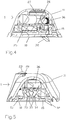
- Fig. 3 shows the safety device 1 Fig. 1 alone in a view of the section along the section line AA Fig. 1b ) in the open state ( Fig. 3a ) and when closed ( Fig. 3b ).
- Fig. 4 shows the securing device alone in a view of the section along the section line BB Fig. 1b ) and Fig. 5 in a view of the section along the section line CC Fig. 1b ) each in the closed state.
- the securing device 1 has a housing comprising a base plate 10 and a cover 11. Cover 11 and base plate 10 are movably connected to one another via a hinge 12. In the open state, the securing device 1 with the base plate 10 can be pushed between the surface of the object 2 and the straps 3 spanning the object 2, so that the straps 3 intersect in the middle of the base plate 10.
- the base plate 10 has two groove-shaped depressions 14 which also intersect to guide the bands 3.
- the lid 11 in the Fig. 2a still in the folded-back state, has cutouts 13 along its edge for the straps 3 running through the securing device 1.
- the cover 11 has a plurality of cylindrical projections 15 on the surface which faces the base plate 10 in the closed state. These projections 15, the function of which will be explained below, are arranged such that they lie in the region of the channel-shaped depressions 14 in the closed state of the securing device 1.
- the cover 11 can be locked with the base plate 10 in the closed state of the securing device 1.
- the locking provided for this purpose comprises a hook-shaped slide 16 which can be moved in the cover 11 between two positions.
- the extended position of the slide 16 shows Fig. 3a ) while the safety device is open, while Fig. 3b ) shows the slide 16 in its inserted position in the closed state of the safety device.
- the slider 16 engages in a recess 17 in the base plate 10 and engages under it with its hook-shaped end 18, the inner edge 19 thereof.
- This engaging occurs when the slider 16 closes the lid 11 starting from its extended position under an oblique angle Angle relative to the base plate 10 is pressed into the lid 11 as soon as it is in Engagement with the recess 17 has come and is present in it.
- a spring 20, which is otherwise arranged between the slide 16 and the cover 11, is also tensioned, which loads the cover 11 in the opening direction or the slide 16 into its extended position and the resistance of which must be overcome when the cover 11 is closed.
- the opening of the lid 11 under the action of the spring 20 is in accordance with the closed state Fig. 3b however, prevented by a magnetic lock 21 provided in the cover 11.
- the lock 21 is of the type known from so-called hard tags.
- a thin pin 22 connected to the slide 16 is inserted into this lock 21 when the slide 16 moves into its inserted position, where it is prevented from moving back by spring-loaded balls.
- Cover 11 and base plate 10 are thereby automatically locked together when the cover 11 is closed in the closed state of the securing device, without further manipulation being necessary for this.
- the balls of the lock 21 must be pulled away from the pin 22 by the force of a magnet to be applied to 23 against the action of a spring 24 acting on them, so that this is free and can be withdrawn from the lock 21.
- the lid 11 jumps open automatically and the slide 16 in its extended position.
- the means for generating the alarm are also essentially arranged in the cover 11. These means comprise a battery 25 (in Fig. 2a ) denotes 25 the battery compartment), electronics (PCB) 26, an acoustic signal transmitter (buzzer) 27, an optical signal transmitter (LED) 28 and a main switch 29.
- the latter is actuated by a pin 30 formed on the slide 16 and closes when the lid is closed 11 and inserted slider 16 the battery circuit.
- the cover 11 is open and the slide 16 is extended, the battery circuit is interrupted by the main switch 29.
- the means for generating an alarm are thereby activated when the safety device is closed and deactivated when the safety device is opened.
- the means for generating the alarm further comprise a mechanical and an optical sensor.
- the mechanical sensor comprises a contact switch 31 in the cover 11 and a pivotable pushbutton 32 in the base plate 10, which interact when the safety device is closed.
- the button 32 is loaded by a spring so that it normally, as in the Figures 3 - 5 shown, protrudes downward over the base plate 10. If, on the other hand, the securing device is of the type Fig. 1 attached to an object 2 and thus with its base plate 10 under a contact pressure caused by the tensioned bands 3 in contact with the object 2, the button 32 is pivoted back by the object 2 into the base plate 10, whereby the contact switch 31 is actuated. The contact switch 31 thereby assumes a switching position from which the electronics 26 infer the presence of the object 2.
- the button 32 swings out of the base plate, the contact switch 31 being actuated and thereby reaching a switching position from which the electronics 26 concludes that there has been no contact with the object and an alarm (acoustically via the buzzer 27 and / or triggered optically via LED 28).
- the contact switch 31 could also have several switching stages, so that only a slight lifting of the security device from the object merely results in a pre-alarm, e.g. a brief flashing of the optical signal generator (LED) 28, generated in the sense of a warning of further manipulation.
- the optical sensor designed as a reflex light barrier is in Fig. 5 recognizable and has a light transmitter 33 and a reflected light receiver 34. It is preferably insensitive to ambient light in that the light transmitter 33 emits infrared light and the reflected light receiver 34 is only sensitive to infrared light.
- the light transmitter 33 When the safety device is closed, the light transmitter 33 emits light at an oblique angle through an opening 35 in the base plate 10. If the safety device in the manner of Fig. 1 is attached to an object 2, part of this light is reflected on the surface of the object 2 and reaches the reflected light receiver 34 through the opening 35. Against direct light from the light transmitter 33 the reflected light receiver 34 shielded. Depending on the nature of the surface in terms of brightness, color and / or gloss, but also depending on the distance to the surface, more or less reflected light will reach the reflected light receiver. In order to take account of the respective circumstances, the electronics first determine the intensity of the light received in each case after the securing device has been attached and closed on an object and store this as a reference value. Then it can react to changes in the received light intensity.
- Such changes are to be expected in particular if the securing device is separated from the object, and a slight lifting of the securing device from the object in the area of the compliance of the object or the tapes may be sufficient.
- Detectable changes can also be caused when a flat object is pushed between the security device and the object, which has slightly different reflection properties, which will usually be the case.
- a flat object in the form of a stiff card between the security device and the object someone could try to remove the security device from the object without the mechanical sensor triggering an alarm by swiveling the button 32 on the flat object when the security device is removed with the flat object is prevented from the base plate 10.
- the optical sensor can also register changes that are produced by moving the security device on an object with a structured surface.
- the securing device should be well fixed on the object with the straps and be as little displaceable as possible.
- the aforementioned cylindrical projections 15 are provided in the cover 11. In the closed state of the securing device, they press on the straps 3, which are guided along the trough-shaped depressions 14 of the base plate 10, and clamp them firmly, so that the securing device 1 cannot be moved along the straps 3.
- the cylindrical projections 15 can consist, for example, of an elastic material.
- the base plate 10 can also be provided with a rubber coating on the side facing the object 2.
- an alarm is only triggered if the displacement exceeds a certain size in each case.
- a light sensor can be used that is sensitive to ambient light.
- the light sensor could e.g. simply react to the difference in brightness that results when the safety device is lifted off the object.
- an electrical resonant circuit consisting of a coil and a capacitor is also present in the cover 11 of the present embodiment, which can be excited and detected by an electronic goods security system, such as is installed in many retail stores.
- the coil has a ferrite core, which is designated by 36.
- the lid 11 springs open under the action of the spring 20 when unlocking and the slide 16 into its extended position, the battery circuit being interrupted by the main switch 29.
- the safety device can then be removed from object 2 without an alarm being triggered.
- the security device according to the invention is designed with regard to the stability of its parts in such a way that it resists attempts to break it open by force to a certain degree.
- the engagement of the hook-shaped end 18 on the slide 16 with the edge 19 is preferably provided. It can be provided, for example, that the hook-shaped end 18 slides over the edge 19 or breaks off the slide 16.
- the slide 16 remains in its inserted position in the cover 11 and with it the pin 30, so that the main switch 29 also remains in its position closing the battery circuit. This means that the means for generating alarms remain active. If the cover 11 is opened after such a violent breaking open, its distance to the object changes, which is detected by both the mechanical and the optical sensor, which then trigger an alarm.
- Fig. 6 shows an extension of the inventive safety device of Fig. 1 around a cable 50, with which this can be connected to yet another object in order to additionally secure this, if necessary.
- the safety device from Fig. 7 there is a two-wire cable 50, one end of which is provided with a plug 51 and is inserted with this plug 51 in the cover 11 of the housing into a plug-in base 52 provided there.
- said cable end with the plug connection consisting of plug 51 and plug base 52 is not accessible from the outside.
- the plug connection cannot be released in the closed state.
- the cable end in the cover 11 is also secured with several baffles to prevent it being pulled out in the closed state.
- the cable 50 protrudes from the housing through one of the cutouts 13 and is provided with a plurality of spiral windings 53, so that its length can be flexibly adapted to the respective distance from the other object.
- the cable 50 is provided with means for attachment to another object.
- Fig. 6 shows a first embodiment of such means in the form of a further, substantially smaller housing 54.
- a mechanical sensor which can detect contact with another object through the further housing 54 and react to loss of contact with the further object.
- This mechanical sensor can in turn be a contact switch with a button 55, which is loaded by a spring such that it normally protrudes slightly beyond the housing 54 on one side.
- the housing 54 is simply attached to a further object such as with an adhesive strip (not shown), in particular one of the type already described, with the side mentioned for example in Fig. 6 Object 60 shown glued, so that the button 55 is pushed back into the housing 54.
- the contact switch closes a circuit via the cable 50 and the plug connection 51, 52, which is connected to the above-described means for generating the alarm in the cover 11 of the safety device. If there is a loss of contact between the further housing and the further object, these means in the cover 11, when activated, generate an alarm of the type also described above.
- a suitable surface for being able to glue the housing 54 as described can be found on most objects find, which accommodates the fact that the housing 54 can be made relatively small, for example only 1 - 4 cm in length and / or width.
- the embodiment according to comes without adhesive strips for attachment to another object Fig. 7 out.
- the further object must have an opening or the like.
- An eyelet 56 is formed in FIG. 8 at the free end of the cable 50.
- the two wires of the cable 50 are electrically connected to one another in a sleeve 57 closing the eyelet 56.
- the cable 50 thereby in turn forms a closed circuit which is monitored for continuity by the alarm means in the cover 11.
- Cable 50 is connected to another object such as object 61 in Fig. 7 connected by its end provided with the plug 51 being passed through a suitable opening 62 in the object 61, subsequently being pushed through the eyelet 56 to form a closed loop 58 and finally being inserted into the plug base 52 in the cover 11 of the housing.
- An alarm is generated here by the alarm means in the cover 11 when the cable 50 is cut, for example, to remove the further object.
Description
Die Erfindung betrifft eine Sicherungsvorrichtung für Objekte, die durch zwei um sie herum gespannte und sich überkreuzende Bänder daran gehindert sind, geöffnet zu werden gemäss dem Oberbegriff des Patentanspruchs 1.The invention relates to a security device for objects that are prevented from being opened by two straps that cross them and intersect each other, according to the preamble of
Zur Sicherung von Waren in Ladengeschäften gegen Diebstahl haben sich elektronische Warensicherungssysteme bewährt. An den zu sichernden Waren werden dabei Tags angebracht, welche durch die Elektronik des Systems über meist am Ausgang der Ladengeschäfte angeordnete Antennen detektierbar sind. Bei den Tags handelt es sich z.B. um elektrische Resonanzschwingkreise mit Resonanzfrequenzen im Radiofrequenzbereich (einige MHz).Electronic anti-theft systems have proven their worth to secure goods in shops against theft. Tags are attached to the goods to be secured, which can be detected by the electronics of the system via antennas usually arranged at the outlet of the shops. The tags are e.g. electrical resonant circuits with resonance frequencies in the radio frequency range (a few MHz).
Damit die Sicherung funktioniert, müssen die Tags mit den zu sichernden Waren so verbunden sein, dass sie von Unbefugten nicht einfach und unbemerkt entfernt werden können. Bei Kleidungsstücken wird dies z.B. dadurch erreicht, dass eine Nadel durch den Stoff gestochen und die Nadelspitze mit einem Schloss gesichert wird, zu dessen Entfernung spezielles Gerät erforderlich ist. Der Tag ist dabei im Nadelkopf (Hard-Tag) oder in dem Schloss untergebracht. Kleine Gegenstände können in durchsichtigen, verriegelbaren Behältern untergebracht werden, die in ihrem Innern den Tag enthalten. Zur Sicherung von Waren, die in Verpackungen wie Kartons oder dergleichen zum Verkauf kommen, kommen Tags in Gehäusen zum Einsatz, die mit Bändern (oder Kabeln) an den Verpackungen befestigt werden.For the security to work, the tags must be connected to the goods to be secured in such a way that unauthorized persons cannot remove them easily and unnoticed. For garments this is e.g. by inserting a needle through the fabric and securing the tip of the needle with a lock that requires special equipment to remove it. The day is housed in the needle head (hard tag) or in the lock. Small items can be stored in clear, lockable containers that hold the day inside. To secure goods that are sold in packaging such as boxes or the like, tags are used in housings that are attached to the packaging with tapes (or cables).
Bei einer Ausführungsform sind die Bänder elektrisch leitend und werden von einer Elektronik auf elektrischen Durchgang überwacht. Werden sie zum unbefugten Entfernen der Sicherungsvorrichtung durchtrennt, erzeugt die Elektronik einen Alarm. Zum Aufwickeln und Spannen der Bänder ist in den Gehäusen eine Mechanik untergebracht. Da diese nicht beliebig voluminös sein darf, ist der Verstellungsbereich der Bänder begrenzt, was ihre Anwendung auf Verpackungen in einem bestimmten Grössenbereich einschränkt.In one embodiment, the tapes are electrically conductive and are monitored for electrical continuity by electronics. If they are cut to remove the security device without authorization, the electronics generate an alarm. A mechanism is housed in the housing for winding and tensioning the tapes. Since this must not be voluminous, the adjustment range is of the belts, which limits their use on packaging in a certain size range.
In
Bei geeigneter geometrischer Anordnung kann mit Bändern auch verhindert werden, dass die Verpackungen geöffnet werden. Häufig wird der Inhalt der Verpackung beim Kauf nicht kontrolliert. Nicht selten stellt sich dann beim Auspacken zu Hause heraus, dass der Inhalt den Erwartungen nicht entspricht. Das kann dadurch verursacht sein, dass die Verpackung beim Transport, im Lager oder im Verkaufsgeschäft geöffnet und die darin enthaltene Ware entnommen und im besten Fall noch gegen eine andere, meist aber minderwertige Ware ausgetauscht wurde. Auch werden hochwertige, teure Waren nicht selten in Verpackungen billigerer Waren plaziert, um an der Kasse nur den niedrigeren Preis der billigeren Ware bezahlen zu müssen.With a suitable geometric arrangement, tapes can also be used to prevent the packaging from being opened. Often the content of the packaging is not checked when buying. It is not uncommon then when unpacking at home it turns out that the content does not meet expectations. This can be caused by the packaging being opened during transport, in the warehouse or in the sales shop and the goods contained therein removed and, at best, exchanged for another, but usually inferior product. Also, high-quality, expensive goods are often placed in the packaging of cheaper goods, so that only the lower price of the cheaper goods has to be paid at the checkout.
Die Erfindung stellt sich die Aufgabe, eine Sicherungsvorrichtung der eingangs genannten Art anzugeben, welche sich an Objekten wie grösseren Verpackungskartons so anbringen lässt, dass sie von diesen nicht unbemerkt entfernt werden kann, die keine aufwendige Mechanik benötigt und dennoch einen ausreichenden Schutz gewährleistet.The invention has for its object to provide a security device of the type mentioned, which can be attached to objects such as larger packaging boxes so that they can not be removed unnoticed by them, which does not require complex mechanics and still ensures adequate protection.
Erfindungsgemäss wird dies bei einer solchen Sicherungsvorrichtung durch die Merkmale des Anspruchs 1 erreicht.According to the invention, this is achieved in such a safety device by the features of
Dabei umfassen die Mittel zur Erzeugung eines Alarms einen mechanischen und ggf. einen optischen Sensor. Der mechanische Sensor kann im geschlossenen Zustand durch die Basisplatte Kontakt mit dem Objekt detektieren und auf Kontaktverlust mit dem Objekt reagieren. Er löst insbesondere dann einen Alarm aus, wenn die Sicherungsvorrichtung unbefugt vom Objekt entfernt wird. Der optische Sensor, sofern vorhanden, emittiert im geschlossenen Zustand Licht durch die Basisplatte, kann Reflexionen dieses Lichtes vom Objekt durch die Basisplatte erfassen und kann auf Veränderungen dieser Reflexionen reagieren. Der optische Sensor kann damit ebenfalls einen Alarm auslösen, wenn die Sicherungsvorrichtung unbefugt vom Objekt entfernt wird.The means for generating an alarm include a mechanical and possibly an optical sensor. When closed, the mechanical sensor can detect contact with the object through the base plate and react to loss of contact with the object. It triggers an alarm in particular if the security device is removed from the object without authorization. The optical sensor, if present, emits light through the base plate when closed, can detect reflections of this light from the object through the base plate and can react to changes in these reflections. The optical sensor can thus also trigger an alarm if the security device is removed from the object without authorization.
Bei der Anbringung der Sicherungsvorrichtung am Objekt mittels Bändern könnte es möglich sein, die Sicherungsvorrichtung auf dem Objekt etwas zu verschieben oder einen flachen Gegenstand zwischen die Sicherungsvorrichtung und das Objekt zu schieben. Letzteres, um beispielsweise das Reagieren des mechanischen Sensors zu verhindern. Dabei würde jedoch jeweils der optische Sensor ansprechen.When attaching the security device to the object by means of tapes, it could be possible to move the security device slightly on the object or to push a flat object between the security device and the object. The latter, for example, to prevent the mechanical sensor from reacting. However, the optical sensor would respond in each case.
Die Basisplatte und der Deckel können zur leichteren Handhabung über ein Scharnier beweglich miteinander verbunden sein.The base plate and the cover can be movably connected to one another via a hinge for easier handling.
Der optische Sensor kann eine Reflexlichtschranke oder ein Bildsensor sein, welcher vorzugsweise unempfindlich gegenüber Umgebungslicht ist. Das von ihm emittierte Licht ist weiter vorzugsweise Infrarot-Licht. Es kann aber auch vorgesehen sein, dass der optische Sensor auf Umgebungslicht reagiert, insbesondere, wenn die Sicherungsvorrichtung vom Objekt abgehoben wird.The optical sensor can be a reflex light barrier or an image sensor, which is preferably insensitive to ambient light. The light it emits is further preferably infrared light. But it can also be provided that the optical sensor reacts to ambient light, especially when the security device is lifted from the object.
Die Mittel zur Erzeugung eines Alarms weisen einen von einer elektronischen Warensicherungsanlage detektierbaren Resonanzschwingkreis auf. Das zu sichernde Objekt kann dann zusammen mit der erfindungsgemässen Sicherungsvorrichtung, also ohne diese zuvor vom Objekt zu entfernen, nicht einfach aus einem durch eine elektronischen Warensicherungsanlage überwachten Bereich wie einem Verkaufsgeschäft entfernt werden. Sobald die elektronische Warensicherungsanlage den Resonanzschwingkreis in der erfindungsgemässen Sicherungsvorrichtung detektiert, gibt sie Alarm.The means for generating an alarm have a resonant circuit which can be detected by an electronic goods security system. The object to be secured can then, together with the security device according to the invention, that is to say without first removing it from the object, not simply removed from an area monitored by an electronic goods security system, such as a retail store. As soon as the electronic goods security system detects the resonant circuit in the security device according to the invention, it issues an alarm.
Umgekehrt können die Mittel zur Erzeugung eines Alarms der erfindungsgemässen Sicherungsvorrichtung einen Alarm erzeugen, wenn der Resonanzschwingkreis durch eine elektronische Warensicherungsanlage durch das von dieser erzeugte elektromagnetische Wechselfeld angeregt wird.Conversely, the means for generating an alarm of the security device according to the invention can generate an alarm if the resonant circuit is excited by an electronic goods security system by the electromagnetic alternating field generated by it.
Die Verriegelung wird beim und durch das Schliessen der Sicherungsvorrichtung aktiviert. Lösbar sein sollte ist nur mit einem speziellen Werkzeug, darunter einem Magnet-Öffner, wie er zum Öffnen eines Hard-Tags der eingangs erwähnten Art verwendet wird, sowie ggf. zusätzlich mit einem Schlüssel.The lock is activated when and by closing the safety device. It should only be possible to solve it with a special tool, including a magnet opener, such as is used to open a hard tag of the type mentioned at the beginning, and, if necessary, also with a key.
Die Mittel zur Erzeugung eines Alarms werden beim und durch das Schliessen der Sicherungsvorrichtung aktiviert (im Sinne von scharf gemacht). Ein Alarm wird durch diese Aktivierung natürlich noch nicht ausgelöst. Allerdings können die Mittel zur Erzeugung eines Alarms so ausgebildet sein, dass sie ihre Aktivierung durch ein Blinksignal und/oder einen akustischen Kontrollton signalisieren.The means for generating an alarm are activated when and by closing the safety device (in the sense of armed). An activation is of course not yet triggered by this activation. However, the means for generating an alarm can be designed so that they signal their activation by a flashing signal and / or an acoustic control tone.
Die Deaktivierung der Mittel zur Erzeugung eines Alarms erfolgt beim befugten Öffnen, wozu vorzugsweise ein spezieller Magnetöffner bzw. ein Schlüssel verwendet werden muss. Es könnte auch eine Deaktivierung elektronisch per Fernbedienung oder mittels einer Deaktivatorplatte vorgesehen sein. In diesem Fall würde ein Alarm z.B. auch dann noch ausgelöst, wenn die Sicherungsvorrichtung mit einem dazu vorgesehenen speziellen Magnetöffner bzw. Schlüssel geöffnet wird. Bei einer gewaltsamen Öffnung der Sicherungsvorrichtung sollte natürlich ebenfalls eine Deaktivierung der Mittel zur Erzeugung eines Alarms unterbleiben und ein Alarm ausgelöst werden.The means for generating an alarm are deactivated when authorized opening, for which purpose a special magnetic opener or a key must preferably be used. Deactivation could also be provided electronically by remote control or by means of a deactivator plate. In this case, an alarm would also be triggered, for example, if the safety device was provided with one special magnetic opener or key is opened. If the safety device is opened by force, the means for generating an alarm should of course also be deactivated and an alarm triggered.
Die Mittel zur Erzeugung eines Alarms können zur Erzeugung eines bezüglich seiner Intensität und/oder Dauer mehrstufigen Alarms ausgebildet sein. Das kann dazu verwendet werden, bereits bei leichtem Abheben der Sicherungsvorrichtung von dem Objekt und/oder bei einer nur geringen Verschiebung der Sicherungsvorrichtung auf dem Objekt einen warnenden Voralarm auszulösen. Das kann ggf. schon ausreichen, die manipulierende Person vor weitergehenden Manipulationen abzuschrecken, ohne allgemeinen Aufruhr zu verursachen. Insbesondere kann lediglich ein Alarm auf einer niedrigeren als der höchsten Alarmstufe ausgelöst werden, wenn nur der optische Sensor (19) anspricht. Vor allem wenn dieser empfindlich eingestellt ist, kann dies schon beim befugten Hantieren mit dem Objekt vorkommen.The means for generating an alarm can be designed to generate an alarm which is multi-level in terms of its intensity and / or duration. This can be used to trigger a warning pre-alarm when the safety device is lifted slightly from the object and / or when the safety device is only slightly moved on the object. This may be enough to deter the manipulator from further manipulation without causing general turmoil. In particular, an alarm can only be triggered at a lower than the highest alarm level if only the optical sensor (19) responds. Especially if this is set sensitively, this can already occur when handling the object with authorization.
Die erfindungsgemässe Sicherungsvorrichtung ist so ausgebildet, dass sie mit zwei um das zu sichernde Objekt gespannten Bändern an dem Objekt anbringbar ist. Dies wird dadurch erreicht, dass die Basisplatte im offenen Zustand der Sicherungsvorrichtung zwischen die Bänder und das Objekt einschiebbar ist und dass die Basisplatte und der Deckel im geschlossenen Zustand der Sicherungsvorrichtung in Eingriff mit den Bändern mittels der Verriegelung verriegelbar sind. Bei einem Verkaufskarton können die Bänder dabei so angebracht sein, dass der Verkaufskarton, zumindest ohne grössere Beschädigungen an ihm zu verursachen, nicht geöffnet werden kann.The security device according to the invention is designed such that it can be attached to the object with two straps stretched around the object to be secured. This is achieved in that the base plate can be inserted between the straps and the object in the open state of the securing device and that the base plate and the lid can be locked in engagement with the straps by means of the lock when the securing device is closed. In the case of a sales box, the straps can be attached in such a way that the sales box cannot be opened, at least without causing major damage to it.
Für ein sicheres und festes Führen der Bänder können die Basisplatte rinnenförmige Vertiefungen und der Deckel mehrere Aussparungen aufweisen, in welche die Bänder einlegbar sind. Zudem kann die Sicherungsvorrichtung Mittel gegen Verrutschen der Basisplatte auf dem zu sichernden Objekt aufweisen, was bei einer Anbringung mit Bändern möglich sein kann. Dies kann z.B. eine Gummischicht oder dergleichen sein, welche an der dem Objekt zugewandten Seite der Basisplatte angeordnet ist.For a secure and firm guiding of the tapes, the base plate can have channel-shaped depressions and the cover can have a plurality of recesses into which the tapes can be inserted. In addition, the securing device can have means to prevent the base plate from slipping on the object to be secured, which can be possible when attached with tapes. This can e.g. a rubber layer or the like, which is arranged on the side of the base plate facing the object.
Die Erfindung soll nachfolgend anhand eines Ausführungsbeispiels im Zusammenhang mit der Zeichnung näher erläutert werden. Es zeigen:
- Fig. 1
- eine erfindungsgemässe Sicherungsvorrichtung an einem mit zwei Bändern umspannten Objekt unter a) in einer perspektivischen Ansicht und unter b) in einer Draufsicht;
- Fig. 2
- perspektivische Ansichten der Sicherungsvorrichtung aus
Fig. 1 unter a) im offenen Zustand und unter b) im geschlossenen Zustand; - Fig. 3
- eine Ansicht auf den Schnitt A-A aus
Fig. 1b ) unter a) im offenen Zustand und unter b) im geschlossenen Zustand; - Fig. 4
- eine Ansicht auf den Schnitt B-B aus
Fig. 1b ) im geschlossenen Zustand; - Fig. 5
- eine Ansicht auf den Schnitt C-C aus
Fig. 1b ) im geschlossenen Zustand; - Fig. 6
- eine erfindungsgemässe Sicherungsvorrichtung, die
um ein Kabel 50 gemäss einer ersten Ausführungsform erweitert ist, mit welchem Kabel sie sich mit noch einem anderen Objekt verbinden lässt; und - Fig. 7
- eine andere Ausführungsform eines solchen Kabels.
- Fig. 1
- a security device according to the invention on an object spanned by two bands under a) in a perspective view and under b) in a plan view;
- Fig. 2
- perspective views of the safety device
Fig. 1 under a) in the open state and under b) in the closed state; - Fig. 3
- a view of the section AA
Fig. 1b ) under a) in the open state and under b) in the closed state; - Fig. 4
- a view of the section BB from
Fig. 1b ) when closed; - Fig. 5
- a view of the section CC from
Fig. 1b ) when closed; - Fig. 6
- a security device according to the invention, which is extended by a
cable 50 according to a first embodiment, with which cable it can be connected to yet another object; and - Fig. 7
- another embodiment of such a cable.
In den Figuren sind übereinstimmende Teile mit denselben Bezugszeichen versehen.In the figures, identical parts are provided with the same reference symbols.
In
Die Sicherungsvorrichtung 1 weist ein Gehäuse umfassend eine Basisplatte 10 und einen Deckel 11 auf. Deckel 11 und Basisplatte 10 sind über ein Scharnier 12 beweglich miteinander verbunden. Im offenen Zustand kann die Sicherungsvorrichtung 1 mit der Basisplatte 10 zwischen die Oberfläche des Objekts 2 und die das Objekt 2 umspannenden Bänder 3 geschoben werden, so dass die Bänder 3 sich in der Mitte der Basisplatte 10 kreuzen. Die Basisplatte 10 weist zur Führung der Bänder 3 zwei sich ebenfalls kreuzende, rinnenförmige Vertiefungen 14 auf. Der Deckel 11, in der
Der Deckel 11 ist mit der Basisplatte 10 im geschlossenen Zustand der Sicherungsvorrichtung 1 verriegelbar. Die dazu vorgesehene Verriegelung umfasst einen hakenförmigen Schieber 16, der im Deckel 11 zwischen zwei Stellungen verschiebbar ist. Die ausgefahrene Stellung des Schiebers 16 zeigt
Das Öffnen des Deckels 11 unter der Wirkung der Feder 20 wird im geschlossenen Zustand gemäss
Zum Lösen der Verriegelung müssen die Kugeln des Schlosses 21 durch die Kraft eines bei 23 anzulegenden Magneten gegen die Wirkung einer auf sie einwirkenden Feder 24 von dem Stift 22 weggezogen werden, so dass dieser frei wird und aus dem Schloss 21 zurückgezogen werden kann. Unter der Wirkung der Feder 20 springt dabei der Deckel 11 selbsttätig auf und der Schieber 16 in seine ausgefahrene Stellung.To release the lock, the balls of the
In dem Deckel 11 sind im Wesentlichen auch die Mittel zur Erzeugung des Alarms angeordnet. Diese Mittel umfassen eine Batterie 25 (in
Die Mittel zur Erzeugung des Alarms umfassen weiter einen mechanischen und einen optischen Sensor. Der mechanische Sensor umfasst im Deckel 11 einen Kontaktschalter 31 und in der Basisplatte 10 einen schwenkbar gelagerten Taster 32, welche im geschlossenen Zustand der Sicherungsvorrichtung zusammenwirken. Der Taster 32 ist von einer Feder so belastet, dass er normalerweise, wie in den
Wird die Sicherungsvorrichtung im geschlossenen Zustand von dem Objekt 2 getrennt, nachdem z.B. die Bänder 3 durchschnitten wurden, schwenkt der Taster 32 aus der Basisplatte aus, wobei der Kontaktschalter 31 betätigt wird und hierdurch eine Schaltstellung erreicht, aus der die Elektronik 26 auf den Kontaktverlust mit dem Objekt schliesst und einen Alarm (akustisch über den Buzzer 27 und/oder optisch über die LED 28) auslöst. Der Kontaktschalter 31 könnte auch mehrere Schaltstufen aufweisen, so dass ein nur leichtes Abheben der Sicherungsvorrichtung vom Objekt lediglich einen Voralarm, z.B. ein kurzes Aufleuchten des optischen Signalgebers (LED) 28, im Sinne einer Warnung vor weitergehenden Manipulationen generiert.If the safety device is separated from the
Der als Reflexlichtschranke ausgebildete optische Sensor ist in
Der Lichtsender 33 strahlt im geschlossenen Zustand der Sicherungsvorrichtung Licht unter einem schrägen Winkel durch eine Öffnung 35 in der Basisplatte 10 ab. Wenn die Sicherungsvorrichtung nach Art von
Solche Veränderungen sind insbesondere zu erwarten, wenn die Sicherungsvorrichtung vom Objekt getrennt wird, wobei schon ein leichtes Abheben der Sicherungsvorrichtung vom Objekt im Bereich der Nachgiebigkeit des Objekts oder der Bänder ausreichend sein kann. Detektierbare Veränderungen können auch verursacht werden, wenn ein flacher Gegenstand zwischen die Sicherungsvorrichtung und das Objekt geschoben wird, der etwas andere Reflexionseigenschaften aufweist, was meist der Fall sein wird. Durch Einschieben eines flachen Gegenstandes in Form einer steifen Karte zwischen die Sicherungsvorrichtung und das Objekt könnte jemand versuchen, die Sicherungsvorrichtung vom Objekt zu entfernen, ohne dass dabei der mechanische Sensor Alarm auslöst, indem beim Abnehmen der Sicherungsvorrichtung mit dem flachen Gegenstand der Taster 32 am Ausschwenken aus der Basisplatte 10 gehindert wird.Such changes are to be expected in particular if the securing device is separated from the object, and a slight lifting of the securing device from the object in the area of the compliance of the object or the tapes may be sufficient. Detectable changes can also be caused when a flat object is pushed between the security device and the object, which has slightly different reflection properties, which will usually be the case. By inserting a flat object in the form of a stiff card between the security device and the object, someone could try to remove the security device from the object without the mechanical sensor triggering an alarm by swiveling the
Der optische Sensor kann auch Veränderungen registrieren, die durch Verschieben der Sicherungsvorrichtung auf einem Objekt mit strukturierter Oberfläche erzeugt werden. Damit hierdurch beim bestimmungsgemässen Hantieren mit dem Objekt keine Alarme ausgelöst werden, sollte die Sicherungsvorrichtung auf dem Objekt mit den Bändern gut fixiert und möglichst wenig verschiebbar sein. Im vorliegenden Ausführungsbeispiel sind deshalb die vorangehend erwähnten zylinderförmigen Vorsprünge 15 im Deckel 11 vorgesehen. Sie drücken im geschlossenen Zustand der Sicherungsvorrichtung auf die Bänder 3, welche entlang der rinnenförmigen Vertiefungen 14 der Basisplatte 10 geführt sind und klemmen diese fest, so dass sich die Sicherungsvorrichtung 1 nicht entlang der Bändern 3 verschieben lässt. Die zylinderförmigen Vorsprünge 15 können z.B. aus einem elastischen Material bestehen. Um eine unerwünschte Verschiebung der Sicherungsvorrichtung 1 relativ zur Oberfläche des Objekts 2 zusätzlich zu erschweren, kann die Basisplatte 10 an der dem Objekt 2 zugewandten Seite auch mit einer Gummibeschichtung versehen sein.The optical sensor can also register changes that are produced by moving the security device on an object with a structured surface. To ensure that no alarms are triggered when the object is handled as intended, the securing device should be well fixed on the object with the straps and be as little displaceable as possible. In the present exemplary embodiment, therefore, the aforementioned
Andererseits oder zusätzlich kann vorgesehen sein, einen Alarm nur auszulösen, wenn die Verschiebung jeweils eine bestimmte Grösse überschreitet. Auch könnte die Erzeugung eines Alarms oder Voralarms von geringerer Intensität und/oder Dauer, wie oben für den mechanischen Sensor beschrieben, vorgesehen sein.On the other hand or in addition, it can be provided that an alarm is only triggered if the displacement exceeds a certain size in each case. The generation of an alarm or pre-alarm of lower intensity and / or duration, as described above for the mechanical sensor, could also be provided.
In einer alternativen Ausführungsform kann ein Lichtsensor eingesetzt werden, der empfindlich gegenüber Umgebungslicht ist. Der Lichtsensor könnte hierbei z.B. einfach auf den Helligkeitsunterschied reagieren, der sich beim Abheben der Sicherungsvorrichtung vom Objekt ergibt.In an alternative embodiment, a light sensor can be used that is sensitive to ambient light. The light sensor could e.g. simply react to the difference in brightness that results when the safety device is lifted off the object.
Als ein weiteres Mittel zur Alarmerzeugung ist im Deckel 11 der vorliegenden Ausführungsform noch ein elektrischer Resonanzschwingkreis aus Spule und Kondensator vorhanden, der von einer elektronischen Warensicherungsanlage, wie sie in vielen Verkaufsgeschäften installiert ist, angeregt und detektiert werden kann. Die Spule weist einen Ferritkern auf, der mit 36 bezeichnet ist. Bei Anregung des Resonanzschwingkreises löst die Elektronik 26 einen Alarm aus.As a further means of generating the alarm, an electrical resonant circuit consisting of a coil and a capacitor is also present in the
Wie erläutert, springt der Deckel 11 unter der Wirkung der Feder 20 beim Entriegeln auf und der Schieber 16 in seine ausgefahrene Stellung, wobei der Batteriestromkreis durch den Hauptschalter 29 unterbrochen wird. Danach kann die Sicherungsvorrichtung vom Objekt 2 abgenommen werden, ohne dass ein Alarm ausgelöst wird.As explained, the
Die erfindungsgemässe Sicherungsvorrichtung ist bezüglich der Stabilität ihrer Teile so ausgebildet, dass sie Versuchen, sie gewaltsam aufzubrechen, bis zum einem gewissen Grad widersteht. Als schwächstes Glied, das, wenn überhaupt, als erstes bei dem Versuch einer gewaltsamen Öffnung nachgibt, ist dabei vorzugsweise der Eingriff des hakenförmigen Endes 18 am Schieber 16 mit der Kante 19 vorgesehen. Es kann z.B. vorgesehen sein, dass das hakenförmige Ende 18 über die Kante 19 rutscht oder vom Schieber 16 abbricht. Der Schieber 16 verbleibt dabei in seiner eingeschobenen Position im Deckel 11 und mit ihm der Zapfen 30, so dass auch der Hauptschalter 29 in seiner den Batteriestromkreis schliessenden Stellung bleibt. Damit bleiben auch die Mittel zur Alarmerzeugung aktiv. Wird der Deckel 11 nach einem solchen gewaltsamen Aufbrechen aufgeklappt, verändert sich sein Abstand zum Objekt, was sowohl von dem mechanischen als auch dem optischen Sensor detektiert wird, die daraufhin einen Alarm auslösen.The security device according to the invention is designed with regard to the stability of its parts in such a way that it resists attempts to break it open by force to a certain degree. As the weakest link that yields first, if at all, when trying to open it violently, the engagement of the hook-shaped
Ohne Klebstreifen zur Anbringung an einem weiteren Objekt kommt die Ausführungsform gemäss
- 1-1-
- SicherungsvorrichtungSafety device
- 22nd
- Objektobject
- 33rd
- BänderTapes
- 1010th
- BasisplatteBase plate
- 1111
- Deckelcover
- 1212th
- Scharnierhinge
- 1313
- AussparungenRecesses
- 1414
- rinnenförmige Vertiefungentrough-shaped depressions
- 1515
- VorsprüngeLedges
- 1616
- SchieberSlider
- 1717th
- AussparungRecess
- 1818th
- hakenförmiges Endehook-shaped end
- 1919th
- innere Kanteinner edge
- 2020th
- Federfeather
- 2121
- magnetisches Schlossmagnetic lock
- 2222
- Stiftpen
- 2323
- Anlegeposition für MagnetenPosition for magnets
- 2424th
- Federfeather
- 2525th
- Batterie/BatteriefachBattery / battery compartment
- 2626
- Elektronik (PCB)Electronics (PCB)
- 2727
- akustischer Signalgeber (Buzzer)acoustic signal generator (buzzer)
- 2828
- optischer Signalgeber (LED)optical signaling device (LED)
- 2929
- HauptschalterMain switch
- 3030th
- ZapfenCones
- 3131
- KontaktschalterContact switch
- 3232
- TasterButton
- 3333
- LichtsenderLight transmitter
- 3434
- ReflexlichtempfängerLens Flare Receiver
- 3535
- Öffnungopening
- 3636
- FerritkernFerrite core
- 5050
- Kabelelectric wire
- 5151
- Steckerplug
- 5252
- StecksockelSocket
- 5353
- spiralförmige Windungenspiral turns
- 5454
- kleineres Gehäusesmaller housing
- 5555
- TasterButton
- 5656
- Öseeyelet
- 5757
- HülseSleeve
- 5858
- geschlossene Schlaufeclosed loop
- 6060
- weiteres Objektanother object
- 6161
- weiteres Objektanother object
- 6262
- Öffnung im weiteren Objekt.Opening in the further object.
Claims (11)
- Security device for objects (2) that are prevented from being opened by two intersecting strips (3) clamped around said objects, wherein the security device (1) has a housing with a baseplate (10) and a cover (11) and means for generating an alarm when the security device (1) is removed from the object (2) without authorization, wherein the security device (1) has an open and a closed state, wherein, in the closed state, the baseplate (10) and the cover (11) can be locked to one another by way of a locking mechanism, wherein the baseplate (10), in the open state, can be inserted between the intersecting strips (3) and the object (2), wherein the baseplate (10) and the cover (11), in the closed state, can be locked in engagement the stripes (3), wherein the two strips run through the security device (1) and intersect therein when the security device (1) is locked in the closed state, so as to engage with the two strips, wherein the security device (1), when it is locked in engagement with the two strips and in the closed state, is held on the surface of the object (2) by the tension of the strips (3), wherein the locking mechanism is activated by closing the security device and wherein the means for generating an alarm comprise a resonant oscillating circuit which can be detected by an electronic goods security system, characterized in that the means for generating an alarm comprise a mechanical sensor (31, 32) having a contact switch (31) that, in the closed state, can detect contact with the object (2) through the baseplate (10) and respond to a loss of contact with the object (2), in that the means for generating an alarm are activated when the security device is closed, in that the means for generating an alarm are deactivated when the security device is opened after the locking mechanism has been released, in that the locking mechanism comprises a slider (16) and a magnetic lock (21) and in that closing the security device comprises moving the slider (16) from a retracted position into an inserted position.
- Security device according to Claim 1, characterized in that the baseplate (10) and the cover (11) are connected movably to one another by way of a hinge (12) .
- Security device according to either of Claims 1 - 2, characterized in that the means for generating an alarm comprise an optical sensor (33, 34) that, in the closed state, emits light through the baseplate (10), can detect reflections of this light from the object (2) through the baseplate (10) and can respond to changes in these reflections.
- Security device according to one of Claims 1 - 3, characterized in that the optical sensor is a reflex light barrier (33, 34) or an image sensor and is preferably insensitive to ambient light, wherein the light emitted thereby is further preferably infrared light.
- Security device according to one of Claims 1 - 4, characterized in that the locking mechanism can also be released mechanically using a key.
- Security device according to one of Claims 1 - 5, characterized in that the means for generating an alarm can be deactivated through remote operation or by way of a deactivator plate.
- Security device according to one of Claims 1 - 6, characterized in that the means for generating an alarm are designed to generate an alarm that has multiple levels in terms of its intensity and/or duration.
- Security device according to one of Claims 1 - 7, characterized in that the baseplate (10) has groove-shaped indentations (14) and/or the cover (11) has a plurality of recesses (13) into which the strips (3) can be laid.
- Security device according to one of Claims 1 - 8, characterized in that said security device (1) has means (15) for preventing the baseplate (10) from slipping on the object (2) to be secured.
- Security device according to one of Claims 1 - 9, characterized in that at the magnetic lock (21) a thin pin (22) connected to the slider (16) is inserted into this lock (21) when the slider (16) moves from its retracted position into its inserted position and is prevented from moving backwards there by spring-loaded balls and in which, in order to release the locking mechanism, the balls of the lock (21) are moved by the force of a magnet away from the pin (22) counter to the effect of a spring (24) acting thereon.
- Security device according to one of Claims 1 - 10, characterized in that the means for generating an alarm generate an alarm when the resonant oscillating circuit is excited by an electronic goods security system.
Applications Claiming Priority (4)
| Application Number | Priority Date | Filing Date | Title |
|---|---|---|---|
| CH00902/10A CH703299A1 (en) | 2010-06-07 | 2010-06-07 | Safety device for objects. |
| PCT/CH2011/000134 WO2011153651A1 (en) | 2010-06-07 | 2011-06-07 | Securing device for objects |
| EP11725859.0A EP2577631B1 (en) | 2010-06-07 | 2011-06-07 | Securing device for objects |
| EP15158287.1A EP2905759B1 (en) | 2010-06-07 | 2011-06-07 | Securing device fo objects |
Related Parent Applications (2)
| Application Number | Title | Priority Date | Filing Date |
|---|---|---|---|
| EP11725859.0A Division EP2577631B1 (en) | 2010-06-07 | 2011-06-07 | Securing device for objects |
| EP15158287.1A Division EP2905759B1 (en) | 2010-06-07 | 2011-06-07 | Securing device fo objects |
Publications (2)
| Publication Number | Publication Date |
|---|---|
| EP3206197A1 EP3206197A1 (en) | 2017-08-16 |
| EP3206197B1 true EP3206197B1 (en) | 2020-04-08 |
Family
ID=43827221
Family Applications (3)
| Application Number | Title | Priority Date | Filing Date |
|---|---|---|---|
| EP17162106.3A Active EP3206197B1 (en) | 2010-06-07 | 2011-06-07 | Securing device for objects |
| EP11725859.0A Active EP2577631B1 (en) | 2010-06-07 | 2011-06-07 | Securing device for objects |
| EP15158287.1A Active EP2905759B1 (en) | 2010-06-07 | 2011-06-07 | Securing device fo objects |
Family Applications After (2)
| Application Number | Title | Priority Date | Filing Date |
|---|---|---|---|
| EP11725859.0A Active EP2577631B1 (en) | 2010-06-07 | 2011-06-07 | Securing device for objects |
| EP15158287.1A Active EP2905759B1 (en) | 2010-06-07 | 2011-06-07 | Securing device fo objects |
Country Status (4)
| Country | Link |
|---|---|
| US (2) | US9524626B2 (en) |
| EP (3) | EP3206197B1 (en) |
| CH (1) | CH703299A1 (en) |
| WO (1) | WO2011153651A1 (en) |
Families Citing this family (32)
| Publication number | Priority date | Publication date | Assignee | Title |
|---|---|---|---|---|
| US9404291B1 (en) | 2015-03-04 | 2016-08-02 | Checkpoint Systems, Inc. | Device and method for an alarming strap tag |
| CH703299A1 (en) | 2010-06-07 | 2011-12-15 | Pataco Ag Ind Und Unterhaltungselektronik | Safety device for objects. |
| US9103142B2 (en) * | 2011-02-24 | 2015-08-11 | Invue Security Products Inc. | Merchandise display security tether including releasable adhesive |
| PL2920015T3 (en) | 2012-10-17 | 2020-10-05 | Hutchinson S.A. | Fire suppression module, modular system including same, and method of installing modular system |
| MX2015010678A (en) | 2013-02-20 | 2016-04-11 | Giovanni Salvo | Device and package for retail theft prevention. |
| EP3054814A4 (en) | 2013-10-08 | 2016-09-21 | Invue Security Products Inc | Quick release sensor for merchandise display |
| US10180017B2 (en) * | 2015-06-08 | 2019-01-15 | Southern Imperial Llc | Security device with reusable base member |
| US20170175426A1 (en) * | 2015-12-18 | 2017-06-22 | Checkpoint Systems, Inc. | Anti-impact locking feature |
| USD899218S1 (en) * | 2016-04-10 | 2020-10-20 | Delta Lock Company, LLC | Locking device |
| GB2549699B (en) * | 2016-04-18 | 2021-07-07 | Sekura Global Ip Llp | Security tag |
| CH712486A1 (en) | 2016-05-24 | 2017-11-30 | Pataco Ag | Adhesive label, security cable, fuse arrangement and method for securing objects. |
| US9934665B1 (en) | 2016-09-16 | 2018-04-03 | Ningsheng Zhang | Box edge security device |
| US9965933B1 (en) | 2017-03-08 | 2018-05-08 | Checkpoint Systems, Inc. | Product strap detection apparatus and method |
| US20180340357A1 (en) * | 2017-05-25 | 2018-11-29 | Invue Security Products Inc. | Package wrap |
| US11619073B2 (en) * | 2017-07-28 | 2023-04-04 | Checkpoint Systems, Inc. | Locking sled security device |
| CN107444771A (en) * | 2017-08-04 | 2017-12-08 | 思创医惠科技股份有限公司 | A kind of packing box protection device and its alarm method |
| JP6975973B2 (en) * | 2018-01-22 | 2021-12-01 | エム・ケー・パビック株式会社 | Anti-theft device and attachment |
| WO2019152683A1 (en) * | 2018-02-01 | 2019-08-08 | Edge Security Products, Inc. | Box edge security device |
| WO2019204851A1 (en) * | 2018-04-26 | 2019-10-31 | Veder Waterbox Gmbh | Delivery device, delivery system, and method for delivering shipments |
| AT16444U1 (en) * | 2018-04-26 | 2019-10-15 | Veder Waterbox Gmbh | Security delivery device and system for protecting a good |
| US11908307B2 (en) | 2018-06-07 | 2024-02-20 | William J. Hoofe, IV | Security system |
| CN112368751A (en) * | 2018-06-10 | 2021-02-12 | 杭州泰铭信息技术有限公司 | Security device system composition, method of manufacture and use |
| CN110006553B (en) * | 2019-04-29 | 2024-01-16 | 国家电网有限公司 | Passive wireless temperature measuring device |
| GB2591269B (en) * | 2020-01-23 | 2023-10-18 | Sekura Global Ip Llp | Security tag |
| US11429830B2 (en) | 2020-03-05 | 2022-08-30 | Fasteners For Retail, Inc. | Security tag holder and assembly for use with package having curved surfaces |
| USD956607S1 (en) | 2020-04-16 | 2022-07-05 | Fasteners For Retail, Inc. | Security tag holder |
| US20210355715A1 (en) * | 2020-05-18 | 2021-11-18 | Fasteners For Retail, Inc. | Security tag holder |
| WO2022083872A1 (en) | 2020-10-22 | 2022-04-28 | Pataco Ag | Security bag |
| US11879269B2 (en) | 2021-05-10 | 2024-01-23 | Innovation Lock, Llc | Ratchet lock assemblies |
| USD988835S1 (en) | 2021-05-10 | 2023-06-13 | Innovation Lock, Llc | Ratchet locking device |
| US20220398884A1 (en) * | 2021-06-09 | 2022-12-15 | Ashten Gilliard | Retail Point of Sale Security System |
| CN116101155B (en) * | 2023-03-21 | 2023-09-12 | 张家港欣迈克五金工具有限公司 | Cargo fixing device for night driving |
Family Cites Families (37)
| Publication number | Priority date | Publication date | Assignee | Title |
|---|---|---|---|---|
| US4620182A (en) * | 1985-01-10 | 1986-10-28 | Check Mate Systems, Inc. | Security apparatus for retail goods |
| US5349834A (en) | 1992-03-17 | 1994-09-27 | Tortoise Products, Inc. | Adhesively mounted security system |
| WO1993024373A1 (en) * | 1992-06-02 | 1993-12-09 | Minnesota Mining And Manufacturing Company | Variable stretch detackification adhesive tape unitizer system |
| DE4222849C2 (en) * | 1992-07-11 | 2000-02-10 | Beiersdorf Ag | Use a strip of adhesive film for releasable gluing |
| US5910768A (en) * | 1995-04-04 | 1999-06-08 | Ott; Reinhold | Anti-theft device |
| US5627520A (en) * | 1995-07-10 | 1997-05-06 | Protell Systems International, Inc. | Tamper detect monitoring device |
| US5699591A (en) | 1996-05-29 | 1997-12-23 | Kane; Roger | Security anchor |
| US5709110A (en) | 1996-10-07 | 1998-01-20 | Greenfield; Jack | Security system for a lap-top computer |
| US5886633A (en) * | 1998-06-29 | 1999-03-23 | I.S.P.A. Woodworking Limited | Selectively disconnectable sensor switch for an alarm |
| EP0978812B1 (en) * | 1998-08-03 | 2006-04-12 | Hi-G-Tek Ltd | Self-locking seal |
| US6105922A (en) | 1999-08-09 | 2000-08-22 | Derman; Jay S. | Support device for attaching wire cable or a padlock shackle to portable equipment |
| US6641910B1 (en) * | 1999-08-24 | 2003-11-04 | 3M Innovative Properties Company | Stretch releasing adhesive tape with segmented release liner |
| US6578394B2 (en) * | 2001-09-06 | 2003-06-17 | Hewlett-Packard Development Company | Portable computer security device |
| US6811126B2 (en) * | 2001-09-13 | 2004-11-02 | 3M Innovative Properties Company | Stretch releasing adhesive tape article with flexible cover |
| DE10251133B3 (en) * | 2002-10-31 | 2004-07-29 | Gerd Reime | Device for controlling lighting, in particular for vehicle interiors, and method for controlling it |
| US7501937B2 (en) * | 2003-08-27 | 2009-03-10 | Omega Patents, L.L.C. | Vehicle security device including pre-warn indicator and related methods |
| US7168275B2 (en) * | 2004-12-28 | 2007-01-30 | Alpha Security Products, Inc. | Cable wrap security device |
| US7671741B2 (en) * | 2005-07-27 | 2010-03-02 | Lax Michael R | Anti-theft security device and perimeter detection system |
| US20070171061A1 (en) * | 2006-01-13 | 2007-07-26 | Alpha Security Products, Inc. | Theft deterrent device with dual sensor assembly |
| JP5043340B2 (en) * | 2006-02-01 | 2012-10-10 | スリーエム イノベイティブ プロパティズ カンパニー | Article mounting kit |
| US8081075B2 (en) * | 2006-03-31 | 2011-12-20 | Checkpoint Systems, Inc. | Tether cord and sensor alarms |
| US20080246656A1 (en) * | 2006-04-25 | 2008-10-09 | Ghazarian Ohanes D | Automatic GPS tracking system with passive battery circuitry |
| CH698863B1 (en) * | 2006-07-19 | 2009-11-30 | Pataco Ag Ind Und Unterhaltung | safety device |
| US20080018066A1 (en) * | 2006-07-20 | 2008-01-24 | Kehau Pickford | Footwear contact indication system |
| US7522048B2 (en) * | 2007-01-12 | 2009-04-21 | Checkpoint Systems, Inc. | Banding clip alarm |
| US8122744B2 (en) * | 2007-03-28 | 2012-02-28 | Checkpoint Systems, Inc. | Cable wrap security device |
| GB2462964B (en) * | 2007-06-08 | 2012-09-05 | Guard Rfid Solutions Inc | Method and system for determining RFID tag tampering |
| US8650097B2 (en) * | 2007-12-03 | 2014-02-11 | Yu Yung Choi | System and method for streamlined registration of products over a communication network and for verification and management of information related thereto |
| US8305219B2 (en) * | 2008-02-22 | 2012-11-06 | Xiao Hui Yang | EAS tag using tape with conductive element |
| US8274391B2 (en) * | 2008-02-22 | 2012-09-25 | Xiao Hui Yang | EAS tag using tape with conductive element |
| US20090235428A1 (en) * | 2008-03-20 | 2009-09-24 | Horne Iii Franklin Stebin | Item Wrapping Assistance Device |
| US20100147041A1 (en) * | 2008-12-16 | 2010-06-17 | Sandisk Il Ltd. | Tethering arrangement for portable electronic devices |
| US8514070B2 (en) * | 2010-04-07 | 2013-08-20 | Securealert, Inc. | Tracking device incorporating enhanced security mounting strap |
| CH703299A1 (en) * | 2010-06-07 | 2011-12-15 | Pataco Ag Ind Und Unterhaltungselektronik | Safety device for objects. |
| US9103142B2 (en) | 2011-02-24 | 2015-08-11 | Invue Security Products Inc. | Merchandise display security tether including releasable adhesive |
| US8541745B2 (en) * | 2011-11-16 | 2013-09-24 | Motorola Mobility Llc | Methods and devices for clothing detection about a wearable electronic device |
| WO2013149631A1 (en) * | 2012-04-03 | 2013-10-10 | Hartmut Schmitz | Closure device for a cable sling, securing device, high-pressure device, and method for assembling the securing device |
-
2010
- 2010-06-07 CH CH00902/10A patent/CH703299A1/en not_active Application Discontinuation
-
2011
- 2011-06-07 EP EP17162106.3A patent/EP3206197B1/en active Active
- 2011-06-07 WO PCT/CH2011/000134 patent/WO2011153651A1/en active Application Filing
- 2011-06-07 EP EP11725859.0A patent/EP2577631B1/en active Active
- 2011-06-07 US US13/702,891 patent/US9524626B2/en active Active
- 2011-06-07 EP EP15158287.1A patent/EP2905759B1/en active Active
-
2016
- 2016-11-11 US US15/349,721 patent/US10134248B2/en active Active
Non-Patent Citations (1)
| Title |
|---|
| None * |
Also Published As
| Publication number | Publication date |
|---|---|
| US9524626B2 (en) | 2016-12-20 |
| EP2905759A1 (en) | 2015-08-12 |
| US10134248B2 (en) | 2018-11-20 |
| EP2577631B1 (en) | 2015-03-11 |
| EP3206197A1 (en) | 2017-08-16 |
| EP2577631A1 (en) | 2013-04-10 |
| WO2011153651A1 (en) | 2011-12-15 |
| US20130169440A1 (en) | 2013-07-04 |
| CH703299A1 (en) | 2011-12-15 |
| EP2905759B1 (en) | 2017-03-22 |
| US20170323536A1 (en) | 2017-11-09 |
Similar Documents
| Publication | Publication Date | Title |
|---|---|---|
| EP3206197B1 (en) | Securing device for objects | |
| DE60204869T2 (en) | Theft prevention, in particular for sales agent expenses | |
| DE102008009491B4 (en) | Device for securing goods | |
| DE602005005091T2 (en) | Safety device for a bottle | |
| CH684134A5 (en) | On an object attachable safety trailer for signaling an attempted theft. | |
| DE19713110A1 (en) | Portable surveillance system e.g. for shop-lifting prevention | |
| DE112008002047T5 (en) | Antitheft device | |
| DE102009049738A1 (en) | Device for securing objects | |
| DD294584A5 (en) | IDENTIFICATION MARK FOR A SYSTEM FOR PREVENTING LOADING POWER | |
| DE112004000006T5 (en) | Security container with connected first and second security devices | |
| EP2772890B1 (en) | Alarm device | |
| DE202018100247U1 (en) | Goods security device with enveloped engagement pin | |
| WO2008009148A1 (en) | Securing device | |
| WO2008144952A1 (en) | Container for protecting an object against theft, and tool and method for opening the container | |
| WO2021214458A1 (en) | Security device | |
| DE102004041602A1 (en) | Goods security device with variable individual magnetic locks has number of separate clamp elements adjustable in angular position and/or asymmetrically arranged relative to prong inserted in hosing | |
| DE3916615C2 (en) | ||
| DE2248443A1 (en) | SIGNAL DEVICE FOR SECURING OBJECTS AGAINST THEFT | |
| DE202007013449U1 (en) | Anti-theft device for securing goods and accessories against theft | |
| DE102004027089A1 (en) | Anti theft device for use with articles is attached by a strip that is looped round the article with the end inserted into the security module housing and is retained | |
| DE19512567C1 (en) | Theft protection device, esp. for radio-, TV-, video- and telephone equipment | |
| DE4418542A1 (en) | Anti-theft element | |
| DE102015014920B3 (en) | Divisible device for securing two bands | |
| WO2005041153A2 (en) | Low volume goods security device for fixing to goods | |
| WO1996031852A1 (en) | Anti-theft device |
Legal Events
| Date | Code | Title | Description |
|---|---|---|---|
| PUAI | Public reference made under article 153(3) epc to a published international application that has entered the european phase |
Free format text: ORIGINAL CODE: 0009012 |
|
| STAA | Information on the status of an ep patent application or granted ep patent |
Free format text: STATUS: THE APPLICATION HAS BEEN PUBLISHED |
|
| AC | Divisional application: reference to earlier application |
Ref document number: 2577631 Country of ref document: EP Kind code of ref document: P Ref document number: 2905759 Country of ref document: EP Kind code of ref document: P |
|
| AK | Designated contracting states |
Kind code of ref document: A1 Designated state(s): AL AT BE BG CH CY CZ DE DK EE ES FI FR GB GR HR HU IE IS IT LI LT LU LV MC MK MT NL NO PL PT RO RS SE SI SK SM TR |
|
| AX | Request for extension of the european patent |
Extension state: BA ME |
|
| STAA | Information on the status of an ep patent application or granted ep patent |
Free format text: STATUS: REQUEST FOR EXAMINATION WAS MADE |
|
| 17P | Request for examination filed |
Effective date: 20180216 |
|
| RBV | Designated contracting states (corrected) |
Designated state(s): AL AT BE BG CH CY CZ DE DK EE ES FI FR GB GR HR HU IE IS IT LI LT LU LV MC MK MT NL NO PL PT RO RS SE SI SK SM TR |
|
| GRAP | Despatch of communication of intention to grant a patent |
Free format text: ORIGINAL CODE: EPIDOSNIGR1 |
|
| STAA | Information on the status of an ep patent application or granted ep patent |
Free format text: STATUS: GRANT OF PATENT IS INTENDED |
|
| INTG | Intention to grant announced |
Effective date: 20191108 |
|
| GRAS | Grant fee paid |
Free format text: ORIGINAL CODE: EPIDOSNIGR3 |
|
| GRAA | (expected) grant |
Free format text: ORIGINAL CODE: 0009210 |
|
| STAA | Information on the status of an ep patent application or granted ep patent |
Free format text: STATUS: THE PATENT HAS BEEN GRANTED |
|
| AC | Divisional application: reference to earlier application |
Ref document number: 2905759 Country of ref document: EP Kind code of ref document: P Ref document number: 2577631 Country of ref document: EP Kind code of ref document: P |
|
| AK | Designated contracting states |
Kind code of ref document: B1 Designated state(s): AL AT BE BG CH CY CZ DE DK EE ES FI FR GB GR HR HU IE IS IT LI LT LU LV MC MK MT NL NO PL PT RO RS SE SI SK SM TR |
|
| REG | Reference to a national code |
Ref country code: CH Ref legal event code: EP Ref country code: AT Ref legal event code: REF Ref document number: 1255409 Country of ref document: AT Kind code of ref document: T Effective date: 20200415 |
|
| REG | Reference to a national code |
Ref country code: DE Ref legal event code: R096 Ref document number: 502011016609 Country of ref document: DE |
|
| REG | Reference to a national code |
Ref country code: IE Ref legal event code: FG4D Free format text: LANGUAGE OF EP DOCUMENT: GERMAN |
|
| REG | Reference to a national code |
Ref country code: CH Ref legal event code: NV Representative=s name: RENTSCH PARTNER AG, CH |
|
| REG | Reference to a national code |
Ref country code: NL Ref legal event code: MP Effective date: 20200408 |
|
| REG | Reference to a national code |
Ref country code: LT Ref legal event code: MG4D |
|
| PG25 | Lapsed in a contracting state [announced via postgrant information from national office to epo] |
Ref country code: IS Free format text: LAPSE BECAUSE OF FAILURE TO SUBMIT A TRANSLATION OF THE DESCRIPTION OR TO PAY THE FEE WITHIN THE PRESCRIBED TIME-LIMIT Effective date: 20200808 Ref country code: SE Free format text: LAPSE BECAUSE OF FAILURE TO SUBMIT A TRANSLATION OF THE DESCRIPTION OR TO PAY THE FEE WITHIN THE PRESCRIBED TIME-LIMIT Effective date: 20200408 Ref country code: GR Free format text: LAPSE BECAUSE OF FAILURE TO SUBMIT A TRANSLATION OF THE DESCRIPTION OR TO PAY THE FEE WITHIN THE PRESCRIBED TIME-LIMIT Effective date: 20200709 Ref country code: NO Free format text: LAPSE BECAUSE OF FAILURE TO SUBMIT A TRANSLATION OF THE DESCRIPTION OR TO PAY THE FEE WITHIN THE PRESCRIBED TIME-LIMIT Effective date: 20200708 Ref country code: FI Free format text: LAPSE BECAUSE OF FAILURE TO SUBMIT A TRANSLATION OF THE DESCRIPTION OR TO PAY THE FEE WITHIN THE PRESCRIBED TIME-LIMIT Effective date: 20200408 Ref country code: PT Free format text: LAPSE BECAUSE OF FAILURE TO SUBMIT A TRANSLATION OF THE DESCRIPTION OR TO PAY THE FEE WITHIN THE PRESCRIBED TIME-LIMIT Effective date: 20200817 Ref country code: LT Free format text: LAPSE BECAUSE OF FAILURE TO SUBMIT A TRANSLATION OF THE DESCRIPTION OR TO PAY THE FEE WITHIN THE PRESCRIBED TIME-LIMIT Effective date: 20200408 Ref country code: NL Free format text: LAPSE BECAUSE OF FAILURE TO SUBMIT A TRANSLATION OF THE DESCRIPTION OR TO PAY THE FEE WITHIN THE PRESCRIBED TIME-LIMIT Effective date: 20200408 |
|
| PG25 | Lapsed in a contracting state [announced via postgrant information from national office to epo] |
Ref country code: LV Free format text: LAPSE BECAUSE OF FAILURE TO SUBMIT A TRANSLATION OF THE DESCRIPTION OR TO PAY THE FEE WITHIN THE PRESCRIBED TIME-LIMIT Effective date: 20200408 Ref country code: RS Free format text: LAPSE BECAUSE OF FAILURE TO SUBMIT A TRANSLATION OF THE DESCRIPTION OR TO PAY THE FEE WITHIN THE PRESCRIBED TIME-LIMIT Effective date: 20200408 Ref country code: HR Free format text: LAPSE BECAUSE OF FAILURE TO SUBMIT A TRANSLATION OF THE DESCRIPTION OR TO PAY THE FEE WITHIN THE PRESCRIBED TIME-LIMIT Effective date: 20200408 Ref country code: BG Free format text: LAPSE BECAUSE OF FAILURE TO SUBMIT A TRANSLATION OF THE DESCRIPTION OR TO PAY THE FEE WITHIN THE PRESCRIBED TIME-LIMIT Effective date: 20200708 |
|
| PG25 | Lapsed in a contracting state [announced via postgrant information from national office to epo] |
Ref country code: AL Free format text: LAPSE BECAUSE OF FAILURE TO SUBMIT A TRANSLATION OF THE DESCRIPTION OR TO PAY THE FEE WITHIN THE PRESCRIBED TIME-LIMIT Effective date: 20200408 |
|
| REG | Reference to a national code |
Ref country code: DE Ref legal event code: R097 Ref document number: 502011016609 Country of ref document: DE |
|
| PG25 | Lapsed in a contracting state [announced via postgrant information from national office to epo] |
Ref country code: SM Free format text: LAPSE BECAUSE OF FAILURE TO SUBMIT A TRANSLATION OF THE DESCRIPTION OR TO PAY THE FEE WITHIN THE PRESCRIBED TIME-LIMIT Effective date: 20200408 Ref country code: IT Free format text: LAPSE BECAUSE OF FAILURE TO SUBMIT A TRANSLATION OF THE DESCRIPTION OR TO PAY THE FEE WITHIN THE PRESCRIBED TIME-LIMIT Effective date: 20200408 Ref country code: EE Free format text: LAPSE BECAUSE OF FAILURE TO SUBMIT A TRANSLATION OF THE DESCRIPTION OR TO PAY THE FEE WITHIN THE PRESCRIBED TIME-LIMIT Effective date: 20200408 Ref country code: DK Free format text: LAPSE BECAUSE OF FAILURE TO SUBMIT A TRANSLATION OF THE DESCRIPTION OR TO PAY THE FEE WITHIN THE PRESCRIBED TIME-LIMIT Effective date: 20200408 Ref country code: MC Free format text: LAPSE BECAUSE OF FAILURE TO SUBMIT A TRANSLATION OF THE DESCRIPTION OR TO PAY THE FEE WITHIN THE PRESCRIBED TIME-LIMIT Effective date: 20200408 Ref country code: ES Free format text: LAPSE BECAUSE OF FAILURE TO SUBMIT A TRANSLATION OF THE DESCRIPTION OR TO PAY THE FEE WITHIN THE PRESCRIBED TIME-LIMIT Effective date: 20200408 Ref country code: CZ Free format text: LAPSE BECAUSE OF FAILURE TO SUBMIT A TRANSLATION OF THE DESCRIPTION OR TO PAY THE FEE WITHIN THE PRESCRIBED TIME-LIMIT Effective date: 20200408 Ref country code: RO Free format text: LAPSE BECAUSE OF FAILURE TO SUBMIT A TRANSLATION OF THE DESCRIPTION OR TO PAY THE FEE WITHIN THE PRESCRIBED TIME-LIMIT Effective date: 20200408 |
|
| PLBE | No opposition filed within time limit |
Free format text: ORIGINAL CODE: 0009261 |
|
| STAA | Information on the status of an ep patent application or granted ep patent |
Free format text: STATUS: NO OPPOSITION FILED WITHIN TIME LIMIT |
|
| PG25 | Lapsed in a contracting state [announced via postgrant information from national office to epo] |
Ref country code: SK Free format text: LAPSE BECAUSE OF FAILURE TO SUBMIT A TRANSLATION OF THE DESCRIPTION OR TO PAY THE FEE WITHIN THE PRESCRIBED TIME-LIMIT Effective date: 20200408 Ref country code: PL Free format text: LAPSE BECAUSE OF FAILURE TO SUBMIT A TRANSLATION OF THE DESCRIPTION OR TO PAY THE FEE WITHIN THE PRESCRIBED TIME-LIMIT Effective date: 20200408 |
|
| 26N | No opposition filed |
Effective date: 20210112 |
|
| PG25 | Lapsed in a contracting state [announced via postgrant information from national office to epo] |
Ref country code: LU Free format text: LAPSE BECAUSE OF NON-PAYMENT OF DUE FEES Effective date: 20200607 |
|
| PG25 | Lapsed in a contracting state [announced via postgrant information from national office to epo] |
Ref country code: IE Free format text: LAPSE BECAUSE OF NON-PAYMENT OF DUE FEES Effective date: 20200607 |
|
| PG25 | Lapsed in a contracting state [announced via postgrant information from national office to epo] |
Ref country code: SI Free format text: LAPSE BECAUSE OF FAILURE TO SUBMIT A TRANSLATION OF THE DESCRIPTION OR TO PAY THE FEE WITHIN THE PRESCRIBED TIME-LIMIT Effective date: 20200408 |
|
| PG25 | Lapsed in a contracting state [announced via postgrant information from national office to epo] |
Ref country code: TR Free format text: LAPSE BECAUSE OF FAILURE TO SUBMIT A TRANSLATION OF THE DESCRIPTION OR TO PAY THE FEE WITHIN THE PRESCRIBED TIME-LIMIT Effective date: 20200408 Ref country code: MT Free format text: LAPSE BECAUSE OF FAILURE TO SUBMIT A TRANSLATION OF THE DESCRIPTION OR TO PAY THE FEE WITHIN THE PRESCRIBED TIME-LIMIT Effective date: 20200408 Ref country code: CY Free format text: LAPSE BECAUSE OF FAILURE TO SUBMIT A TRANSLATION OF THE DESCRIPTION OR TO PAY THE FEE WITHIN THE PRESCRIBED TIME-LIMIT Effective date: 20200408 |
|
| PG25 | Lapsed in a contracting state [announced via postgrant information from national office to epo] |
Ref country code: MK Free format text: LAPSE BECAUSE OF FAILURE TO SUBMIT A TRANSLATION OF THE DESCRIPTION OR TO PAY THE FEE WITHIN THE PRESCRIBED TIME-LIMIT Effective date: 20200408 |
|
| P01 | Opt-out of the competence of the unified patent court (upc) registered |
Effective date: 20230512 |
|
| PGFP | Annual fee paid to national office [announced via postgrant information from national office to epo] |
Ref country code: FR Payment date: 20230628 Year of fee payment: 13 Ref country code: DE Payment date: 20230620 Year of fee payment: 13 |
|
| PGFP | Annual fee paid to national office [announced via postgrant information from national office to epo] |
Ref country code: AT Payment date: 20230621 Year of fee payment: 13 |
|
| PGFP | Annual fee paid to national office [announced via postgrant information from national office to epo] |
Ref country code: BE Payment date: 20230620 Year of fee payment: 13 |
|
| PGFP | Annual fee paid to national office [announced via postgrant information from national office to epo] |
Ref country code: GB Payment date: 20230622 Year of fee payment: 13 Ref country code: CH Payment date: 20230702 Year of fee payment: 13 |