EP3199488A1 - Verfahren und vorrichtung zur sterilisierung einer einfülldüse - Google Patents
Verfahren und vorrichtung zur sterilisierung einer einfülldüse Download PDFInfo
- Publication number
- EP3199488A1 EP3199488A1 EP15843260.9A EP15843260A EP3199488A1 EP 3199488 A1 EP3199488 A1 EP 3199488A1 EP 15843260 A EP15843260 A EP 15843260A EP 3199488 A1 EP3199488 A1 EP 3199488A1
- Authority
- EP
- European Patent Office
- Prior art keywords
- filling
- hot water
- chemical agent
- flow rate
- filling nozzle
- Prior art date
- Legal status (The legal status is an assumption and is not a legal conclusion. Google has not performed a legal analysis and makes no representation as to the accuracy of the status listed.)
- Granted
Links
- 238000011049 filling Methods 0.000 title claims abstract description 197
- 230000001954 sterilising effect Effects 0.000 title claims abstract description 81
- 238000000034 method Methods 0.000 title claims abstract description 58
- XLYOFNOQVPJJNP-UHFFFAOYSA-N water Substances O XLYOFNOQVPJJNP-UHFFFAOYSA-N 0.000 claims abstract description 106
- 239000007788 liquid Substances 0.000 claims abstract description 94
- 239000013043 chemical agent Substances 0.000 claims abstract description 88
- 238000004659 sterilization and disinfection Methods 0.000 claims abstract description 45
- 238000011144 upstream manufacturing Methods 0.000 claims abstract description 13
- 238000005422 blasting Methods 0.000 claims description 4
- 239000000945 filler Substances 0.000 description 66
- 238000012544 monitoring process Methods 0.000 description 13
- HEMHJVSKTPXQMS-UHFFFAOYSA-M Sodium hydroxide Chemical compound [OH-].[Na+] HEMHJVSKTPXQMS-UHFFFAOYSA-M 0.000 description 12
- QTBSBXVTEAMEQO-UHFFFAOYSA-N Acetic acid Chemical compound CC(O)=O QTBSBXVTEAMEQO-UHFFFAOYSA-N 0.000 description 9
- KWYUFKZDYYNOTN-UHFFFAOYSA-M Potassium hydroxide Chemical compound [OH-].[K+] KWYUFKZDYYNOTN-UHFFFAOYSA-M 0.000 description 9
- 238000012371 Aseptic Filling Methods 0.000 description 8
- 238000002474 experimental method Methods 0.000 description 8
- 238000002360 preparation method Methods 0.000 description 8
- MHAJPDPJQMAIIY-UHFFFAOYSA-N Hydrogen peroxide Chemical compound OO MHAJPDPJQMAIIY-UHFFFAOYSA-N 0.000 description 6
- KFSLWBXXFJQRDL-UHFFFAOYSA-N Peracetic acid Chemical compound CC(=O)OO KFSLWBXXFJQRDL-UHFFFAOYSA-N 0.000 description 6
- 238000004140 cleaning Methods 0.000 description 6
- 230000008878 coupling Effects 0.000 description 6
- 238000010168 coupling process Methods 0.000 description 6
- 238000005859 coupling reaction Methods 0.000 description 6
- OSVXSBDYLRYLIG-UHFFFAOYSA-N dioxidochlorine(.) Chemical compound O=Cl=O OSVXSBDYLRYLIG-UHFFFAOYSA-N 0.000 description 6
- 230000000694 effects Effects 0.000 description 6
- 239000012459 cleaning agent Substances 0.000 description 4
- 235000011121 sodium hydroxide Nutrition 0.000 description 4
- 239000007921 spray Substances 0.000 description 4
- 239000004155 Chlorine dioxide Substances 0.000 description 3
- CBENFWSGALASAD-UHFFFAOYSA-N Ozone Chemical compound [O-][O+]=O CBENFWSGALASAD-UHFFFAOYSA-N 0.000 description 3
- 239000005708 Sodium hypochlorite Substances 0.000 description 3
- 235000019398 chlorine dioxide Nutrition 0.000 description 3
- 238000010586 diagram Methods 0.000 description 3
- 238000010438 heat treatment Methods 0.000 description 3
- 244000005700 microbiome Species 0.000 description 3
- SUKJFIGYRHOWBL-UHFFFAOYSA-N sodium hypochlorite Chemical compound [Na+].Cl[O-] SUKJFIGYRHOWBL-UHFFFAOYSA-N 0.000 description 3
- 238000005406 washing Methods 0.000 description 3
- 244000269722 Thea sinensis Species 0.000 description 2
- 239000002253 acid Substances 0.000 description 2
- 239000000654 additive Substances 0.000 description 2
- 230000000996 additive effect Effects 0.000 description 2
- 239000003795 chemical substances by application Substances 0.000 description 2
- 239000000470 constituent Substances 0.000 description 2
- 238000005259 measurement Methods 0.000 description 2
- 239000003513 alkali Substances 0.000 description 1
- 238000004891 communication Methods 0.000 description 1
- 238000011161 development Methods 0.000 description 1
- 238000009826 distribution Methods 0.000 description 1
- 235000015203 fruit juice Nutrition 0.000 description 1
- 235000009569 green tea Nutrition 0.000 description 1
- 239000004615 ingredient Substances 0.000 description 1
- 229910052500 inorganic mineral Inorganic materials 0.000 description 1
- 239000011707 mineral Substances 0.000 description 1
- 235000010755 mineral Nutrition 0.000 description 1
- 239000000203 mixture Substances 0.000 description 1
- 238000012986 modification Methods 0.000 description 1
- 230000004048 modification Effects 0.000 description 1
- 235000013616 tea Nutrition 0.000 description 1
Images


Classifications
-
- A—HUMAN NECESSITIES
- A61—MEDICAL OR VETERINARY SCIENCE; HYGIENE
- A61L—METHODS OR APPARATUS FOR STERILISING MATERIALS OR OBJECTS IN GENERAL; DISINFECTION, STERILISATION OR DEODORISATION OF AIR; CHEMICAL ASPECTS OF BANDAGES, DRESSINGS, ABSORBENT PADS OR SURGICAL ARTICLES; MATERIALS FOR BANDAGES, DRESSINGS, ABSORBENT PADS OR SURGICAL ARTICLES
- A61L2/00—Methods or apparatus for disinfecting or sterilising materials or objects other than foodstuffs or contact lenses; Accessories therefor
- A61L2/16—Methods or apparatus for disinfecting or sterilising materials or objects other than foodstuffs or contact lenses; Accessories therefor using chemical substances
- A61L2/18—Liquid substances or solutions comprising solids or dissolved gases
-
- A—HUMAN NECESSITIES
- A61—MEDICAL OR VETERINARY SCIENCE; HYGIENE
- A61L—METHODS OR APPARATUS FOR STERILISING MATERIALS OR OBJECTS IN GENERAL; DISINFECTION, STERILISATION OR DEODORISATION OF AIR; CHEMICAL ASPECTS OF BANDAGES, DRESSINGS, ABSORBENT PADS OR SURGICAL ARTICLES; MATERIALS FOR BANDAGES, DRESSINGS, ABSORBENT PADS OR SURGICAL ARTICLES
- A61L2/00—Methods or apparatus for disinfecting or sterilising materials or objects other than foodstuffs or contact lenses; Accessories therefor
- A61L2/02—Methods or apparatus for disinfecting or sterilising materials or objects other than foodstuffs or contact lenses; Accessories therefor using physical phenomena
- A61L2/04—Heat
-
- B—PERFORMING OPERATIONS; TRANSPORTING
- B08—CLEANING
- B08B—CLEANING IN GENERAL; PREVENTION OF FOULING IN GENERAL
- B08B3/00—Cleaning by methods involving the use or presence of liquid or steam
- B08B3/02—Cleaning by the force of jets or sprays
-
- B—PERFORMING OPERATIONS; TRANSPORTING
- B08—CLEANING
- B08B—CLEANING IN GENERAL; PREVENTION OF FOULING IN GENERAL
- B08B3/00—Cleaning by methods involving the use or presence of liquid or steam
- B08B3/04—Cleaning involving contact with liquid
- B08B3/10—Cleaning involving contact with liquid with additional treatment of the liquid or of the object being cleaned, e.g. by heat, by electricity or by vibration
-
- B—PERFORMING OPERATIONS; TRANSPORTING
- B08—CLEANING
- B08B—CLEANING IN GENERAL; PREVENTION OF FOULING IN GENERAL
- B08B9/00—Cleaning hollow articles by methods or apparatus specially adapted thereto
- B08B9/02—Cleaning pipes or tubes or systems of pipes or tubes
- B08B9/023—Cleaning the external surface
-
- B—PERFORMING OPERATIONS; TRANSPORTING
- B08—CLEANING
- B08B—CLEANING IN GENERAL; PREVENTION OF FOULING IN GENERAL
- B08B9/00—Cleaning hollow articles by methods or apparatus specially adapted thereto
- B08B9/02—Cleaning pipes or tubes or systems of pipes or tubes
- B08B9/027—Cleaning the internal surfaces; Removal of blockages
- B08B9/032—Cleaning the internal surfaces; Removal of blockages by the mechanical action of a moving fluid, e.g. by flushing
- B08B9/0321—Cleaning the internal surfaces; Removal of blockages by the mechanical action of a moving fluid, e.g. by flushing using pressurised, pulsating or purging fluid
- B08B9/0325—Control mechanisms therefor
-
- B—PERFORMING OPERATIONS; TRANSPORTING
- B67—OPENING, CLOSING OR CLEANING BOTTLES, JARS OR SIMILAR CONTAINERS; LIQUID HANDLING
- B67C—CLEANING, FILLING WITH LIQUIDS OR SEMILIQUIDS, OR EMPTYING, OF BOTTLES, JARS, CANS, CASKS, BARRELS, OR SIMILAR CONTAINERS, NOT OTHERWISE PROVIDED FOR; FUNNELS
- B67C3/00—Bottling liquids or semiliquids; Filling jars or cans with liquids or semiliquids using bottling or like apparatus; Filling casks or barrels with liquids or semiliquids
- B67C3/001—Cleaning of filling devices
- B67C3/005—Cleaning outside parts of filling devices
-
- B—PERFORMING OPERATIONS; TRANSPORTING
- B67—OPENING, CLOSING OR CLEANING BOTTLES, JARS OR SIMILAR CONTAINERS; LIQUID HANDLING
- B67C—CLEANING, FILLING WITH LIQUIDS OR SEMILIQUIDS, OR EMPTYING, OF BOTTLES, JARS, CANS, CASKS, BARRELS, OR SIMILAR CONTAINERS, NOT OTHERWISE PROVIDED FOR; FUNNELS
- B67C7/00—Concurrent cleaning, filling, and closing of bottles; Processes or devices for at least two of these operations
-
- A—HUMAN NECESSITIES
- A61—MEDICAL OR VETERINARY SCIENCE; HYGIENE
- A61L—METHODS OR APPARATUS FOR STERILISING MATERIALS OR OBJECTS IN GENERAL; DISINFECTION, STERILISATION OR DEODORISATION OF AIR; CHEMICAL ASPECTS OF BANDAGES, DRESSINGS, ABSORBENT PADS OR SURGICAL ARTICLES; MATERIALS FOR BANDAGES, DRESSINGS, ABSORBENT PADS OR SURGICAL ARTICLES
- A61L2202/00—Aspects relating to methods or apparatus for disinfecting or sterilising materials or objects
- A61L2202/10—Apparatus features
- A61L2202/14—Means for controlling sterilisation processes, data processing, presentation and storage means, e.g. sensors, controllers, programs
-
- A—HUMAN NECESSITIES
- A61—MEDICAL OR VETERINARY SCIENCE; HYGIENE
- A61L—METHODS OR APPARATUS FOR STERILISING MATERIALS OR OBJECTS IN GENERAL; DISINFECTION, STERILISATION OR DEODORISATION OF AIR; CHEMICAL ASPECTS OF BANDAGES, DRESSINGS, ABSORBENT PADS OR SURGICAL ARTICLES; MATERIALS FOR BANDAGES, DRESSINGS, ABSORBENT PADS OR SURGICAL ARTICLES
- A61L2202/00—Aspects relating to methods or apparatus for disinfecting or sterilising materials or objects
- A61L2202/10—Apparatus features
- A61L2202/17—Combination with washing or cleaning means
-
- B—PERFORMING OPERATIONS; TRANSPORTING
- B08—CLEANING
- B08B—CLEANING IN GENERAL; PREVENTION OF FOULING IN GENERAL
- B08B2230/00—Other cleaning aspects applicable to all B08B range
- B08B2230/01—Cleaning with steam
Definitions
- the present invention relates to a method and an apparatus for sterilizing a filling nozzle of a filler that fills a container such as a PET bottle with a drink.
- an aseptic filling apparatus fills a container such as a bottle with a drink
- a container such as a bottle with a drink
- drink supply piping of the aseptic filling apparatus including a surge tank, a liquid feeding pipe, a filler, and filling nozzles in the filler has to be cleaned and sterilized to be aseptic in advance.
- CIP is performed by passing a cleaner containing water and an alkali agent such as caustic soda as an additive through a flow path from the pipe line of the drink filling path to the filing nozzles of the filler and then passing a cleaner containing water and an acid agent as an additive.
- CIP removes a residue of the previous drink in the drink filling path, for example (see Patent Documents 1, 2 and 3, for example).
- SIP is a process to sterilize the interior of the drink supply piping before the drink filling operation is started, and is performed by passing a heated steam or hot water through the drink filling path cleaned by the CIP described above, for example. SIP sterilizes the interior of the drink filling path and makes it aseptic (see the paragraph [0003] in Patent Document 3, for example).
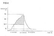
- the drink supply piping is heated to 130°C for 30 minutes.
- This sterilization condition is empirically considered to pose no problem about the sterilization effect. More specifically, heated steam or hot water is passed through the drink supply piping, the temperature of the drink supply piping is measured by temperature sensors at various positions where the temperature of the drink supply piping resists increasing, a timer is activated when the temperatures indicated by all the temperature sensors have reached 130°C, and the heating is ended when the temperature sensors have continued indicating a temperature higher than 130°C for 30 minutes.
- the drink supply piping branches into a large number of branch pipes via a manifold in the filler, and each branch pipe is connected to a filling nozzle at an end thereof.
- An experiment conducted by the inventor has shown that the large number of filling nozzles have different temperatures.
- the temperature sensor is expensive, and there is a problem that the cost significantly increases if a temperature sensor is provided on each filling nozzle in a filler that has 100 or more filling nozzles, for example.
- An object of the present invention is to provide a method and an apparatus for sterilizing a filling nozzle that can solve the problem described above.
- the present invention is configured as described below.
- the invention defined in claim 1 adopts a method for sterilizing a filling nozzle, wherein hot water or a liquid chemical agent is fed to drink supply piping (7)that feeds a drink to a plurality of filling nozzles (2a) at the same time, a flow rate of the hot water or liquid chemical agent is detected at all the filling nozzles (2a) while the hot water or liquid chemical agent is being discharged from all the filling nozzles (2a), a representative temperature of the hot water or liquid chemical agent upstream or downstream of at least one filling nozzle is measured, and a sterilization process is ended when both the flow rate at each filling nozzle and the representative temperature reach respective target values.
- an F value may be calculated based on the representative temperature, and it may be determined whether or not the F value has reached a target value.
- an alarm notifying a failure of the sterilization process may be issued if the flow rate at any of the filling nozzles (2a) is lower than a flow rate required for sterilization.
- an interior and an exterior of the filling nozzles (2a) may be sterilized at the same time by blasting hot water or a liquid chemical agent to the exterior of all the filling nozzles (2a) while the hot water or liquid or gaseous chemical agent is being discharged from all the filling nozzles (2a).
- the interior and the exterior of the filling nozzles may also be washed at the same time with the hot water or liquid chemical agent.
- the invention defined in claim 6 adopts an apparatus for sterilizing a filling nozzle, wherein a flow rate sensor (10a) is provided on each of a plurality of filling nozzles (2a), hot water or a liquid chemical agent is fed to drink supply piping (7) that feeds a drink to the plurality of filling nozzles (2a) at the same time, a flow rate of the hot water or liquid chemical agent is detected at all the filling nozzles (2a) by the respective flow rate sensors (10a) while the hot water or liquid chemical agent is being discharged from all the filling nozzles (2a), a representative temperature of the hot water or liquid chemical agent upstream or downstream of at least one filling nozzle is measured by a temperature sensor, and a sterilization process is ended when both the flow rate at each filling nozzle and the representative temperature reach respective target values.
- a drink metering sensor provided on each filling nozzle (2a) may be used as the flow rate sensor (10a).
- an F value may be calculated based on the representative temperature, and it may be determined whether or not the F value has reached a target value.
- an alarm notifying a failure of the sterilization process may be issued if the flow rate at any of the filling nozzles (2a) is lower than a flow rate required for sterilization.
- all the filling nozzles (2a) may be capable of integrally rotating, and during the rotation, an interior and an exterior of the filling nozzles (2a) may be sterilized at the same time by blasting hot water or a liquid or gaseous chemical agent to the exterior of all the filling nozzles (2a) while the hot water or liquid chemical agent is being discharged from all the filling nozzles (2a).
- the interior and the exterior of the filling nozzles may also be washed at the same time with the hot water or liquid chemical agent.
- hot water or a liquid chemical agent is fed to drink supply piping (7)that feeds a drink to a plurality of filling nozzles (2a) at the same time, a flow rate of the hot water or liquid chemical agent is detected at all the filling nozzles (2a) while the hot water or liquid chemical agent is being discharged from all the filling nozzles (2a), a representative temperature of the hot water or liquid chemical agent upstream or downstream of at least one filling nozzle is measured, and a sterilization process is ended when both the flow rate at each filling nozzle and the representative temperature reach respective target values.
- the representative temperature is measured, it can be confirmed whether or not the interior of the filling nozzles has been properly sterilized. Since the flow rate of the hot water or liquid chemical agent in each filling nozzle is measured, it can be confirmed whether or not the valves of all the filling nozzles have been normally opened, the hot water or liquid chemical agent has smoothly flowed in all the filling nozzles, and the interior of the filling nozzles has been properly sterilized. In addition, since the need of providing the expensive temperature sensor on each filling nozzle is eliminated, and only the representative temperature is measured, SIP of the filler (2) can be managed at relatively low cost.
- the drink metering sensor provided on each filling nozzle (2a) may be used as the flow rate sensor (10a).
- the filler (2) can be manufactured at low cost, and the structural complexity of the filler (2) can be reduced.
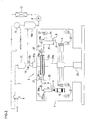
- an aseptic filling apparatus includes a filler 2, and the filler 2 includes a large number of filling nozzles 2a arranged at predetermined angular intervals in a predetermined horizontal plane.
- the aseptic filling apparatus has a drink preparation unit (not shown), and the preparation unit feeds a drink to the filler 2 via a manifold valve 8.
- the preparation unit which produces a drink such as tea or fruit juice by mixing ingredients in desired proportions, is well-known and thus will not be described in detail herein.
- the preparation unit and the filling nozzles 2a in the filler 2 are coupled to each other by drink supply piping 7.
- the manifold valve 8 and a head tank 11 are disposed in this order from upstream to downstream of the flow of the drink.
- the drink supplied to the filler 2 through the drink supply piping 7 is metered and supplied into a bottle b, which is a container, through each filling nozzle 2a.
- the aseptic filling apparatus includes a bottle conveying path that conveys the bottle b to the filler 2 and conveys the bottle b filled with the drink by the filler 2 to a capper (not shown).
- the bottle conveying path is typically formed by a series of a large number of wheels and grippers 4 disposed around the respective wheels, for example.
- the filler 2 is a filling machine that fills a large number of bottles b with a drink at high rate and includes a wheel 5, which forms a part of the conveying path for the bottles b, as shown in FIG. 1 .
- the wheel 5 is attached to a part forming a pivot 21a of a spindle 21 that stands vertically from a floor surface of the aseptic filling apparatus.
- the grippers 4 that grasp neck portions of the bottles b are arranged at regular intervals around the wheel 5.
- the grippers 4 can rotate in one direction integrally with the wheel 5.
- the large number of filling nozzle 2a are arranged at the same intervals as the grippers 4 around the wheel 5.
- An upper part of the spindle 21, which is inhibited from rotating, is fixed to a casing of the filler 2.
- the pivot 21a is provided with a rotary joint 21b at an upper part thereof corresponding to the position where the spindle 21 is fixed.
- An upper manifold 22 is arranged on the pivot 21a at a position below the rotary joint 21b.
- a part of the spindle 21 from the top to the upper manifold 22 is hollow, and the drink supply piping 7 is introduced into the hollow part at the top of the spindle 21.
- Branch pipes 7b of the drink supply piping 7 extend from the upper manifold 22 to the filling nozzles 2a.
- the wheel 5 rotates at high speed
- the bottles b grasped by the grippers 4 are conveyed at high speed on the conveying path in synchronization with the rotation of the wheel 5, and a predetermined amount of the drink is supplied successively to each bottle b when the bottle b is located directly below the nozzle mouth at the lower end of the filling nozzle 2a.
- Each filling nozzle 2a is provided with a drink metering sensor (not shown), and thus, the drink is metered by the drink metering sensor and supplied into each bottle b.
- the filler 2 is housed in an aseptic chamber 3 in its entirety as shown in FIG. 1 so that a sterilized bottle b can be filled with a sterilized drink by preventing a foreign matter such as microorganisms from entering the bottle b.
- the aseptic chamber 3 has an inlet port and an outlet port for the bottles b at an upstream part and a downstream part of the conveying path for the bottles b, respectively.
- hot water or a liquid chemical agent is supplied to the interior of the filler including the interior of the filling nozzles to perform SIP as a sterilization process.
- hydrogen peroxide peracetic acid, acetic acid, ozone water, sodium hypochlorite, sodium hydroxide, potassium hydroxide, acid water, chlorine dioxide or a mixture thereof can be used. Any other liquid that can inactivate microorganisms can be used.
- the filler is provided with a sterilizing apparatus described below.
- a SIP cup 9 is arranged at the nozzle mouth of each filling nozzle 2a of the filler 2 in such a manner that the SIP cup 9 can be connected to and separated from the nozzle mouth.
- a drain pipe 20 formed by a flexible pipe is connected to each cup 9.
- a temperature sensor 10 is disposed to detect the temperature of the hot water or liquid chemical agent supplied to perform SIP as a sterilization process in the drink supply piping 7.
- Information about the temperature measured by the temperature sensor 10 is transmitted to a controller (not shown), so that a representative temperature of the hot water or liquid chemical agent upstream of at least one filling nozzle 2a can be monitored.
- This monitoring is achieved based on an F value calculated from the representative temperature or the like as described later.
- a common temperature monitoring is also possible, although the monitoring based on the F value is preferred from the viewpoint of energy savings.
- Each of the plurality of filling nozzles 2a of the filler 2 is provided with a flow rate sensor 10a.
- the hot water or liquid chemical agent is fed to the drink supply piping 7, the hot water or liquid chemical agent is discharged from all the filling nozzles 2a.
- the flow rate of the hot water or liquid chemical agent is detected at all the filling nozzles 2a by the respective flow rate sensors 10a, and the flow rate sensors 10a each transmit a flow rate signal to the controller.
- the flow rate signals are also used in monitoring of SIP as described later.
- the drink metering sensor provided on each filling nozzle 2a may be used instead of the flow rate sensor 10a.
- Each filling nozzle 2a is provided with the drink metering sensor that allows the drink supplied to the drink supply piping 7 to be supplied in a predetermined amount into the container after SIP.
- the drink metering sensor is used instead of the flow rate sensor 10a, the flow rate of the hot water or liquid chemical agent flowing through each filling nozzle 2a can be measured by the drink metering sensor, and the measurement value can be transmitted to the controller.
- Each cup 9 described above is coupled to a lower manifold 24 by the drain pipe 20.
- the lower manifold 24 is attached to the pivot 21a of the filler 2 and can rotate integrally with the wheel 5, the filling nozzles 2a and the like.
- the drain pipe 20 is provided with a disconnectable coupling 25 at a part where the drain pipe 20 extending from the lower manifold 24 exits to the outside of the aseptic chamber 3.
- the coupling 25 is connected. In this state, the wheel 5, the filling nozzles 2a and the like are inhibited from rotating.
- SIP is completed, and the coupling 25 is disconnected, the wheel 5, the filling nozzles 2a and the like are allowed to rotate.
- the drain pipe 20 is also provided with a temperature sensor 10b at a part outside the aseptic chamber 3. Information about the temperature measured by the temperature sensor 10b is also transmitted to the controller, so that a representative temperature of the hot water or liquid chemical agent downstream of at least one filling nozzle 2a can be monitored. This monitoring is achieved based on the F value calculated from the representative temperature or the like as described later. Instead of the monitoring based on calculation of the F value, a common temperature monitoring is also possible.
- a return pipe 1 extends to the manifold valve 8.
- the return pipe 1 is provided with a reservoir tank 19a of the hot water or chemical agent, a pump 6, a heater 12 and the like at predetermined positions.
- the water, hot water or chemical agent is supplied to the reservoir tank 19a from a supply source 19 thereof.
- the pump 6 and the heater 12 may be provided on another pipe line such as the drink supply piping 7, instead of being provided on the return pipe 1.
- the hot water or liquid chemical agent is heated to a predetermined temperature by the heater 12 and is fed under pressure by the pump 6 to circulate in an annular flow path formed by the drink supply piping 7, the drain pipe 20 and the return pipe 1.
- the hot water or liquid chemical agent sterilizes the interior of the filling nozzles 2a and the interior of the filler 2.
- the controller uses temperature information from the various kinds of temperature sensors 10 and 10b to calculate the F value. In addition, the controller compares a representative temperature with a reference temperature and provides a predetermined output. In addition, the controller provides a predetermined output based on flow rate information from the flow rate sensor 10a. Based on the various kinds of outputs of the controller, the manifold valve 8 provided on the drink supply piping 7, the actuator (not shown), various kinds of switch valves, various kinds of pumps or the like are controlled.
- the bottle b filled with the drink is fed out of the filler 2 and then capped and sealed by the capper (not shown).
- a two-stage rotary joint 21c is provided on the pivot 21a.
- a two-stage manifold 26 is provided on the pivot 21a at a position below the rotary joint 21b.
- a part of the spindle 21 from the top to an upper-stage manifold 26a is hollow, and the drink supply piping 7 is coupled to the top of the spindle 21.
- Branch pipes 7b of the drink supply piping 7 radially extend from the upper-stage manifold 26a to the filling nozzles 2a.
- the wheel 5 rotates at high speed, the bottles b grasped by the grippers 4 are conveyed at high speed on the conveying path in synchronization with the rotation of the wheel 5, and a predetermined amount of the drink is supplied successively to each bottle b when the bottle b is located directly below the nozzle mouth at the lower end of the filling nozzle 2a.
- hot water or a liquid chemical agent is supplied to the interior of the filler 2 including the interior of the filling nozzles 2a to perform SIP as a sterilization process.
- the filler 2 is provided with a sterilizing apparatus described below.
- the SIP cup 9 is arranged at the nozzle mouth of each filling nozzle 2a of the filler 2 in such a manner that the SIP cup 9 can be connected to and separated from the nozzle mouth.
- the drain pipe 20 formed by a flexible pipe is connected to each cup 9.
- the temperature sensor 10 is disposed to detect the temperature of the hot water or liquid chemical agent supplied to perform SIP as a sterilization process in the drink supply piping 7.
- the filling nozzles 2a and the like can rotate with the pivot 21a while the hot water or liquid chemical agent is flowing in the annular flow path.
- COP cleaning out of place
- SOP sterilizizing out of place
- the sterilizer preferably contains liquid or gaseous hydrogen peroxide.
- the sterilizer may contain other constituents, such as acetic acid, peracetic acid, ozone, chlorine dioxide, sodium hypochlorite, sodium hydroxide or potassium hydroxide.
- Information about the temperature measured by the temperature sensor 10 is transmitted to the controller, so that a representative temperature of the hot water or liquid chemical agent upstream of at least one filling nozzle 2a can be monitored. Instead of the monitoring based on calculation of the F value, a common temperature monitoring is also possible.
- Each of the plurality of filling nozzles 2a of the filler 2 is provided with the flow rate sensor 10a.
- the hot water or liquid chemical agent is fed to the drink supply piping 7, the hot water or liquid chemical agent is discharged from all the filling nozzles 2a.
- the flow rate of the hot water or liquid chemical agent is detected at all the filling nozzles 2a by the respective flow rate sensors 10a, and the flow rate sensors 10a each transmit a flow rate signal to the controller.
- the flow rate signals are also used in monitoring of SIP as described later.
- the drink metering sensor (not shown) provided on each filling nozzle 2a may be used instead of the flow rate sensor 10a.
- Each filling nozzle 2a is provided with the drink metering sensor that allows the drink supplied to the drink supply piping 7 to be supplied in a predetermined amount into the bottle b that is the container after SIP.
- the drink metering sensor is used instead of the flow rate sensor 10a, the flow rate of the hot water or liquid chemical agent flowing through each filling nozzle 2a can be measured by the drink metering sensor, and the measurement value can be transmitted to the controller.
- Each cup 9 described above is coupled to a lower-stage manifold 26b by the drain pipe 20.
- the second manifold 26b is also attached to the pivot 21a of the filler 2 and can rotate integrally with the wheel 5, the filling nozzles 2a and the like.
- the spindle 21 has another hollow part between the top thereof and the lower-stage manifold 26b, and the return pipe 1 is coupled to the hollow part at the top of the spindle 21.
- the return pipe 1 is provided with the temperature sensor 10b at a position outside the spindle 21. Information about the temperature measured by the temperature sensor 10b is transmitted to the controller, so that a representative temperature of the hot water or liquid chemical agent downstream of at least one filling nozzle 2a can be monitored. This monitoring is achieved based on the F value calculated from the representative temperature or the like as described later. Instead of the monitoring based on calculation of the F value, a common temperature monitoring is also possible.
- the return pipe 1 extends to the manifold valve 8.
- the return pipe 1 is provided with the reservoir tank 19a of the water or chemical agent, the pump 6, the heater 12 and the like at predetermined positions.
- the water or chemical agent is supplied to the reservoir tank 19a from the supply source 19 thereof.
- the pump 6 and the heater 12 may be provided on another pipe line such as the drink supply piping 7, instead of being provided on the return pipe 1.
- the water or liquid chemical agent is heated by the heater 12 and is fed under pressure by the pump 6 to circulate in the annular flow path formed by the drink supply piping 7, the upper-stage manifold 26a, the branch pipes 7b, the filling nozzles 2a, the drain pipe 20, the lower-stage manifold 26b and the return pipe 1 and heat the annular flow path.
- the hot water or liquid chemical agent sterilizes the interior of the filling nozzles 2a and the interior of the filler 2.
- the controller calculates the F value based on the temperature information from the various kinds of temperature sensors 10 and 10b. In addition, the controller compares the representative temperature with the reference temperature and provides a predetermined output. In addition, the controller provides a predetermined output based on flow rate information from the flow rate sensor 2a. Based on the various kinds of outputs of the controller, the manifold valve 8 provided on the drink supply piping 7, the actuator (not shown), various kinds of switch valves, various kinds of pumps or the like are controlled.
- the bottle b filled with the drink is fed out of the filler 2 and then capped and sealed by the capper (not shown).
- an upper rotary joint 21b is provided on an upper part of the pivot 21a.
- a lower rotary joint 21c is provided on a lower part of the pivot 21a.
- the lower manifold 24 has a configuration similar to that of the upper manifold 22 and is in communication with the return pipe 1 via the lower rotary joint 21c.
- the supply source 19 of the hot water or chemical agent is connected to the drink supply piping 7 via the manifold valve 8.
- the bottle b filled with the drink is fed out of the filler 2 and then capped and sealed by the capper (not shown).
Landscapes
- Health & Medical Sciences (AREA)
- Engineering & Computer Science (AREA)
- Mechanical Engineering (AREA)
- General Health & Medical Sciences (AREA)
- Life Sciences & Earth Sciences (AREA)
- Animal Behavior & Ethology (AREA)
- Epidemiology (AREA)
- Public Health (AREA)
- Veterinary Medicine (AREA)
- Chemical & Material Sciences (AREA)
- Chemical Kinetics & Catalysis (AREA)
- General Chemical & Material Sciences (AREA)
- Filling Of Jars Or Cans And Processes For Cleaning And Sealing Jars (AREA)
- Cleaning By Liquid Or Steam (AREA)
Applications Claiming Priority (2)
| Application Number | Priority Date | Filing Date | Title |
|---|---|---|---|
| JP2014194746A JP5920433B2 (ja) | 2014-09-25 | 2014-09-25 | 充填ノズルの殺菌方法及び装置 |
| PCT/JP2015/076718 WO2016047604A1 (ja) | 2014-09-25 | 2015-09-18 | 充填ノズルの殺菌方法及び装置 |
Publications (3)
| Publication Number | Publication Date |
|---|---|
| EP3199488A1 true EP3199488A1 (de) | 2017-08-02 |
| EP3199488A4 EP3199488A4 (de) | 2018-05-30 |
| EP3199488B1 EP3199488B1 (de) | 2024-05-22 |
Family
ID=55581131
Family Applications (1)
| Application Number | Title | Priority Date | Filing Date |
|---|---|---|---|
| EP15843260.9A Active EP3199488B1 (de) | 2014-09-25 | 2015-09-18 | Verfahren und vorrichtung zur sterilisierung einer einfülldüse |
Country Status (5)
| Country | Link |
|---|---|
| US (2) | US10556028B2 (de) |
| EP (1) | EP3199488B1 (de) |
| JP (1) | JP5920433B2 (de) |
| CN (1) | CN106715320B (de) |
| WO (1) | WO2016047604A1 (de) |
Cited By (2)
| Publication number | Priority date | Publication date | Assignee | Title |
|---|---|---|---|---|
| IT201800005582A1 (it) * | 2018-05-22 | 2019-11-22 | Apparato di riempimento di contenitori in asettico e metodo per sterilizzare tale apparato | |
| EP3825277A3 (de) * | 2017-03-23 | 2022-11-16 | Krones Ag | Vorrichtung zum befüllen eines behälters mit einem füllprodukt |
Families Citing this family (7)
| Publication number | Priority date | Publication date | Assignee | Title |
|---|---|---|---|---|
| JP5920433B2 (ja) | 2014-09-25 | 2016-05-18 | 大日本印刷株式会社 | 充填ノズルの殺菌方法及び装置 |
| JP6265223B2 (ja) * | 2016-04-14 | 2018-01-24 | 大日本印刷株式会社 | 無菌充填装置 |
| DE102016123965A1 (de) * | 2016-12-09 | 2018-06-14 | Krones Ag | Füllvorrichtung zum Abfüllen eines Füllprodukts in einen zu befüllenden Behälter in einer Füllproduktabfüllanlage |
| DE102017104313A1 (de) * | 2017-03-01 | 2018-09-06 | Krones Ag | Vorrichtung zum Befüllen eines Behälters mit einem sterilisierten Füllprodukt |
| JP6521396B2 (ja) * | 2017-07-04 | 2019-05-29 | 大日本印刷株式会社 | 無菌充填システム |
| JP6819709B2 (ja) * | 2019-03-01 | 2021-01-27 | 大日本印刷株式会社 | 容器殺菌装置、内容物充填システム、容器殺菌方法および内容物充填方法 |
| JP7060567B2 (ja) * | 2019-12-10 | 2022-04-26 | 三菱重工機械システム株式会社 | 充填システム、その浄化方法、および製造方法 |
Family Cites Families (27)
| Publication number | Priority date | Publication date | Assignee | Title |
|---|---|---|---|---|
| US4414036A (en) * | 1981-09-18 | 1983-11-08 | Anderson Frank E | Sanitizer system and sanitizing method for carbonated beverage container filler machine |
| JPH0526900U (ja) | 1991-08-08 | 1993-04-06 | キユーピー株式会社 | 充填ノズル洗滌装置 |
| JPH09323794A (ja) * | 1996-06-04 | 1997-12-16 | Shibuya Kogyo Co Ltd | 流量計測式充填機における充填手段洗浄装置 |
| JPH10338296A (ja) | 1997-06-05 | 1998-12-22 | Shintaku Kogyo Kk | 液体充填機の充填ノズルの洗浄装置 |
| JP4282126B2 (ja) | 1998-11-20 | 2009-06-17 | 山陽コカ・コーラボトリング株式会社 | 飲料等の製造ラインの洗浄方法 |
| JP2000246192A (ja) | 1998-12-28 | 2000-09-12 | Kazuo Tokida | 洗浄装置 |
| JP2004001850A (ja) | 2002-05-31 | 2004-01-08 | Daiwa Can Co Ltd | 充填ノズルの洗浄又は殺菌監視装置 |
| SE524496C2 (sv) | 2002-12-13 | 2004-08-17 | Tetra Laval Holdings & Finance | Styrning av steriliseringsanordning |
| US6889603B2 (en) * | 2002-12-24 | 2005-05-10 | Nestec S.A. | Clean-in-place automated food or beverage dispenser |
| JP4133561B2 (ja) | 2003-05-07 | 2008-08-13 | Jsr株式会社 | ポリアミック酸オリゴマー、ポリイミドオリゴマー、溶液組成物、および繊維強化複合材料 |
| US7143793B2 (en) * | 2005-02-18 | 2006-12-05 | Johnsondiversey, Inc. | Cleaning system for a filling machine |
| JP2007022600A (ja) | 2005-07-19 | 2007-02-01 | Toyo Seikan Kaisha Ltd | 食品充填システムにおける充填機の配管系洗浄殺菌方法 |
| JP2007106464A (ja) | 2005-10-14 | 2007-04-26 | Dainippon Printing Co Ltd | 充填機の充填ノズルの処理方法、該方法に使用するノズルホルダ及び充填機 |
| JP2007215893A (ja) | 2006-02-20 | 2007-08-30 | Masanari Tsutsumoto | 殺菌強度測定出力システム |
| JP2007261639A (ja) | 2006-03-29 | 2007-10-11 | Mitsubishi Heavy Industries Food & Packaging Machinery Co Ltd | 殺菌洗浄方法及び装置 |
| JP4876714B2 (ja) * | 2006-05-23 | 2012-02-15 | 花王株式会社 | 充填システムの洗浄装置 |
| WO2008012996A1 (fr) * | 2006-07-26 | 2008-01-31 | Toyo Seikan Kaisha, Ltd. | Procédé pour produire une boisson conditionnée |
| US20100170867A1 (en) | 2007-09-03 | 2010-07-08 | Dai Nippon Printing Co., Ltd | Packaging container and apparatus and method for manufacturing same |
| JP5415116B2 (ja) * | 2009-03-25 | 2014-02-12 | 麒麟麦酒株式会社 | 充填装置の洗浄方法及び充填装置 |
| DE102009023406A1 (de) * | 2009-05-29 | 2010-12-02 | Krones Ag | Blasmaschine mit CIP-Reinigungssystem zur Herstellung von Kunststoff-Flaschen, insbesondere PET-Flaschen |
| DE102011008878A1 (de) * | 2011-01-18 | 2012-07-19 | Khs Gmbh | Füllelement für Behälterbehandlungsmaschinen in Form von Füllmaschinen, Behälterbehandlungsmaschine sowie Verfahren zum Reinigen von Maschinenelementen an Behälterbehandlungsmaschinen |
| JP5974739B2 (ja) * | 2012-09-05 | 2016-08-23 | 大日本印刷株式会社 | 無菌充填用チャンバ内の滅菌方法及び装置 |
| JP6233315B2 (ja) * | 2012-11-16 | 2017-11-22 | 大日本印刷株式会社 | 飲料充填装置の浄化方法 |
| JP5582213B1 (ja) | 2013-03-28 | 2014-09-03 | 大日本印刷株式会社 | フィラーの浄化方法及び装置 |
| JP5574025B1 (ja) * | 2013-06-25 | 2014-08-20 | 大日本印刷株式会社 | 飲料供給系配管の殺菌方法及び装置 |
| CN203573189U (zh) * | 2013-09-27 | 2014-04-30 | 贵州李记食品有限公司 | 蒸汽控制装置 |
| JP5920433B2 (ja) | 2014-09-25 | 2016-05-18 | 大日本印刷株式会社 | 充填ノズルの殺菌方法及び装置 |
-
2014
- 2014-09-25 JP JP2014194746A patent/JP5920433B2/ja active Active
-
2015
- 2015-09-18 US US15/511,691 patent/US10556028B2/en active Active
- 2015-09-18 WO PCT/JP2015/076718 patent/WO2016047604A1/ja active Application Filing
- 2015-09-18 EP EP15843260.9A patent/EP3199488B1/de active Active
- 2015-09-18 CN CN201580049656.5A patent/CN106715320B/zh active Active
-
2019
- 2019-12-13 US US16/713,190 patent/US11103607B2/en active Active
Cited By (3)
| Publication number | Priority date | Publication date | Assignee | Title |
|---|---|---|---|---|
| EP3825277A3 (de) * | 2017-03-23 | 2022-11-16 | Krones Ag | Vorrichtung zum befüllen eines behälters mit einem füllprodukt |
| IT201800005582A1 (it) * | 2018-05-22 | 2019-11-22 | Apparato di riempimento di contenitori in asettico e metodo per sterilizzare tale apparato | |
| WO2019224625A1 (en) * | 2018-05-22 | 2019-11-28 | Gea Procomac S.P.A. | Filling apparatus for filling containers in aseptic conditions and method for sterilizing such apparatus |
Also Published As
| Publication number | Publication date |
|---|---|
| EP3199488A4 (de) | 2018-05-30 |
| EP3199488B1 (de) | 2024-05-22 |
| US11103607B2 (en) | 2021-08-31 |
| JP2016064855A (ja) | 2016-04-28 |
| US20200138992A1 (en) | 2020-05-07 |
| CN106715320B (zh) | 2020-05-08 |
| WO2016047604A1 (ja) | 2016-03-31 |
| US20170290938A1 (en) | 2017-10-12 |
| US10556028B2 (en) | 2020-02-11 |
| CN106715320A (zh) | 2017-05-24 |
| JP5920433B2 (ja) | 2016-05-18 |
Similar Documents
| Publication | Publication Date | Title |
|---|---|---|
| US11103607B2 (en) | Method and apparatus for sterilizing filling nozzle | |
| CN105246821B (zh) | 饮料供给系配管的杀菌方法及装置 | |
| EP3693329B1 (de) | Verfahren zum reinigen und sterilisieren einer getränkefüllvorrichtung | |
| US9751742B2 (en) | Drink filling system and sterilizing method thereof | |
| EP3395750B1 (de) | Migrationsverfahren für sterilisationsbehandlung und produktfüllvorrichtung | |
| JP6519607B2 (ja) | 充填ノズルの殺菌方法及び装置 | |
| EP4269323A1 (de) | Getränkeabfüllsystem und cip-verarbeitungsverfahren | |
| EP3957598A1 (de) | Verfahren zum sterilisieren einer getränkeabfüllvorrichtung und getränkeabfüllvorrichtung | |
| JP6265222B2 (ja) | 充填ノズルの殺菌方法及び装置 | |
| JP6265223B2 (ja) | 無菌充填装置 | |
| EP4269324A1 (de) | Getränkeabfüllsystem und cip-verarbeitungsverfahren |
Legal Events
| Date | Code | Title | Description |
|---|---|---|---|
| STAA | Information on the status of an ep patent application or granted ep patent |
Free format text: STATUS: THE INTERNATIONAL PUBLICATION HAS BEEN MADE |
|
| PUAI | Public reference made under article 153(3) epc to a published international application that has entered the european phase |
Free format text: ORIGINAL CODE: 0009012 |
|
| STAA | Information on the status of an ep patent application or granted ep patent |
Free format text: STATUS: REQUEST FOR EXAMINATION WAS MADE |
|
| 17P | Request for examination filed |
Effective date: 20170330 |
|
| AK | Designated contracting states |
Kind code of ref document: A1 Designated state(s): AL AT BE BG CH CY CZ DE DK EE ES FI FR GB GR HR HU IE IS IT LI LT LU LV MC MK MT NL NO PL PT RO RS SE SI SK SM TR |
|
| AX | Request for extension of the european patent |
Extension state: BA ME |
|
| DAV | Request for validation of the european patent (deleted) | ||
| DAX | Request for extension of the european patent (deleted) | ||
| A4 | Supplementary search report drawn up and despatched |
Effective date: 20180504 |
|
| RIC1 | Information provided on ipc code assigned before grant |
Ipc: B08B 3/02 20060101ALI20180424BHEP Ipc: B67C 3/00 20060101ALI20180424BHEP Ipc: B08B 9/032 20060101AFI20180424BHEP Ipc: B67C 7/00 20060101ALI20180424BHEP |
|
| STAA | Information on the status of an ep patent application or granted ep patent |
Free format text: STATUS: EXAMINATION IS IN PROGRESS |
|
| STAA | Information on the status of an ep patent application or granted ep patent |
Free format text: STATUS: EXAMINATION IS IN PROGRESS |
|
| 17Q | First examination report despatched |
Effective date: 20210818 |
|
| GRAP | Despatch of communication of intention to grant a patent |
Free format text: ORIGINAL CODE: EPIDOSNIGR1 |
|
| STAA | Information on the status of an ep patent application or granted ep patent |
Free format text: STATUS: GRANT OF PATENT IS INTENDED |
|
| INTG | Intention to grant announced |
Effective date: 20240103 |
|
| GRAS | Grant fee paid |
Free format text: ORIGINAL CODE: EPIDOSNIGR3 |
|
| GRAA | (expected) grant |
Free format text: ORIGINAL CODE: 0009210 |
|
| STAA | Information on the status of an ep patent application or granted ep patent |
Free format text: STATUS: THE PATENT HAS BEEN GRANTED |
|
| AK | Designated contracting states |
Kind code of ref document: B1 Designated state(s): AL AT BE BG CH CY CZ DE DK EE ES FI FR GB GR HR HU IE IS IT LI LT LU LV MC MK MT NL NO PL PT RO RS SE SI SK SM TR |
|
| REG | Reference to a national code |
Ref country code: GB Ref legal event code: FG4D |