EP3192953A1 - Türgriffträgervorrichtung eines kraftfahrzeugs - Google Patents
Türgriffträgervorrichtung eines kraftfahrzeugs Download PDFInfo
- Publication number
- EP3192953A1 EP3192953A1 EP16201725.5A EP16201725A EP3192953A1 EP 3192953 A1 EP3192953 A1 EP 3192953A1 EP 16201725 A EP16201725 A EP 16201725A EP 3192953 A1 EP3192953 A1 EP 3192953A1
- Authority
- EP
- European Patent Office
- Prior art keywords
- door handle
- handle support
- locking element
- spring
- locking
- Prior art date
- Legal status (The legal status is an assumption and is not a legal conclusion. Google has not performed a legal analysis and makes no representation as to the accuracy of the status listed.)
- Granted
Links
Images


Classifications
-
- E—FIXED CONSTRUCTIONS
- E05—LOCKS; KEYS; WINDOW OR DOOR FITTINGS; SAFES
- E05B—LOCKS; ACCESSORIES THEREFOR; HANDCUFFS
- E05B85/00—Details of vehicle locks not provided for in groups E05B77/00 - E05B83/00
- E05B85/06—Lock cylinder arrangements
-
- E—FIXED CONSTRUCTIONS
- E05—LOCKS; KEYS; WINDOW OR DOOR FITTINGS; SAFES
- E05B—LOCKS; ACCESSORIES THEREFOR; HANDCUFFS
- E05B79/00—Mounting or connecting vehicle locks or parts thereof
- E05B79/02—Mounting of vehicle locks or parts thereof
- E05B79/06—Mounting of handles, e.g. to the wing or to the lock
-
- E—FIXED CONSTRUCTIONS
- E05—LOCKS; KEYS; WINDOW OR DOOR FITTINGS; SAFES
- E05B—LOCKS; ACCESSORIES THEREFOR; HANDCUFFS
- E05B79/00—Mounting or connecting vehicle locks or parts thereof
- E05B79/10—Connections between movable lock parts
- E05B79/22—Operative connections between handles, sill buttons or lock knobs and the lock unit
-
- E—FIXED CONSTRUCTIONS
- E05—LOCKS; KEYS; WINDOW OR DOOR FITTINGS; SAFES
- E05B—LOCKS; ACCESSORIES THEREFOR; HANDCUFFS
- E05B9/00—Lock casings or latch-mechanism casings ; Fastening locks or fasteners or parts thereof to the wing
- E05B9/04—Casings of cylinder locks
- E05B2009/047—Means for returning cylinder locks to their neutral position
-
- E—FIXED CONSTRUCTIONS
- E05—LOCKS; KEYS; WINDOW OR DOOR FITTINGS; SAFES
- E05B—LOCKS; ACCESSORIES THEREFOR; HANDCUFFS
- E05B15/00—Other details of locks; Parts for engagement by bolts of fastening devices
- E05B15/04—Spring arrangements in locks
- E05B2015/0403—Wound springs
- E05B2015/0406—Wound springs wound in a cylindrical shape
- E05B2015/041—Wound springs wound in a cylindrical shape loaded perpendicular to cylinder axis
Definitions
- the invention relates to a door handle support device of a motor vehicle, comprising a door handle support with a receiving space, a lockable to the door handle carrier locking device which is housed at least partially in the receiving space and the at least one housing, a rotatably mounted in the housing cylinder core and a rotatably connected to the cylinder core driver element for actuating a lock of the motor vehicle, and a restoring element, which exerts a the driver element in a basic position or restoring restoring force on the driver element, wherein the driver element is rotatable against the restoring force of the restoring element from the basic position to an unlocked position or into a locking position ,
- a door handle support device of the type described is, for example, from DE 10 2012 104 889 A1 known, which describes a door handle support with an opening which serves for receiving a housing of a locking device of the type of a lock cylinder.
- a locking device of the type described above is also known from the prior art and is used in combination with a mechanical key for unlocking and locking a vehicle-mounted lock.
- a cylinder core is rotatably mounted in the housing, wherein the cylinder core is rotatably coupled to a driver element.
- the driver element is for actuation of the vehicle-mounted lock from a basic position in various working positions can be transferred, which are known to be referred to as an unlocking position and a locking position.
- a return element formed in the manner of a spring element ensures that the driver element is repeatedly moved back into the basic position.
- the spring element is within the housing of the locking device housed and arranged in extension of the cylinder core axially behind the longitudinal end of the cylinder core and the housing, resulting in an increase in the installation space of the locking device and consequently the door handle support device by itself.
- This has the disadvantageous consequence that the depth of the door of the motor vehicle must take into account this installation depth. For in the total depth of the door, so the extension of the door outside to the inside of the door, in general, in addition, the depth is taken into account, which is needed so that the window can be passed when opening on the door handle support device.
- the depth to sink the window pane is as good as not to reduce, so that the installation depth of the door handle support device determines the total depth of the door significantly.
- the invention has for its object to develop a door handle support device of a motor vehicle in a structurally simple manner and cost, which has a small installation depth and through which the total depth of the door can be reduced.
- this object is achieved in that the restoring element is arranged radially around the cylinder core around and outside of the housing.
- the invention provides a door handle support device in a structurally simple manner and cost-effectively, by means of which the total depth of the door can be reduced to a minimum.
- the restoring element is disposed within the housing and axially behind the longitudinal end of the cylinder core, this installation depth is saved by the invention, because the restoring element is in particular arranged radially around the housing around, so that according to the invention no installation space in the depth direction, ie axially behind the longitudinal end of the cylinder core, is needed, but this space is saved, so that the installation depth of the Door handle support device and thus the total depth of the door can be kept low.
- the restoring element is arranged around the outer circumference of the cylinder core.
- the invention provides that a wheel-shaped or disc-shaped locking element for coupling with the lock of the motor vehicle is rotatably mounted on the door handle carrier, wherein the driver is rotatably connected to the wheel-shaped locking element. More specifically, the driver element is inserted into a centrally formed in the locking member receptacle, whereby the rotationally fixed connection is made.
- the locking element lies substantially flat within a recess formed in the door handle carrier, so that the installation depth of the door handle carrier device is not impaired.
- the return element is attached to the locking element holding.
- the restoring element is designed as at least one spring element with a first spring leg and a second spring leg, wherein the first spring leg and the second spring leg are spring-loaded against each other and apply the restoring force, which via the locking element acts on the driver element.
- the invention provides in a further embodiment that at least one support arm is formed on the locking element, via which the at least one spring element is held on the locking element.
- the spring element or the restoring element are therefore not attached to the cylinder core or the door handle support, but to the locking element, which facilitates the assembly of the door handle support device, because the return element can be pre-assembled on the locking element, before the locking element itself is rotatably mounted on the door handle support.
- the invention provides, in a further embodiment, that both the first spring leg and the second spring leg are respectively supported on a support extension formed on the door handle carrier.
- the Abstützansatz serves as a structurally particularly simple to design stationary reference point.
- the two spring legs can be spring-loaded against each other and can apply the restoring force, it is in another embodiment of the invention of particular advantage, when both the first spring leg and the second spring legs respectively abut against a formed on the locking element movement approach, so that during a movement the driver element from the basic position in the unlocked position or in the locking position, the two spring legs are spring-loaded against each other and apply the restoring force.
- At least one guide arm is formed on the door handle support, which extends in the longitudinal direction of the housing and the peripheral edge of the wheel-shaped locking element at least in the normal position and at least during a movement the basic position engages behind in the unlocked position or in the locking position.
- the invention provides in a further embodiment that the peripheral edge of the wheel-shaped locking element has at least one mounting recess, wherein the locking element for mounting on the door handle support is rotatable in a mounting position, in which the at least one guide arm with the at least one mounting recess in alignment is arranged and does not engage behind the peripheral edge of the wheel-shaped or disc-shaped locking element.
- the invention provides in a further embodiment, that on the wheel-shaped locking element, a lever arm is formed, which extends radially over the Extending the peripheral edge of the locking element and can be coupled to the lock of the motor vehicle.
- the entire assembly of locking device, locking element, which is attached to the driving element of the locking device, and restoring element, which is non-rotatably mounted on the locking element and is supported on the door handle support can be carried out with a small installation depth, which is further supported by the lever arm, which projects radially beyond the peripheral edge of the locking element.
- FIG. 1 is a vehicle or motor vehicle 1 in the form of a car exemplified, which in the example of four doors 2 (two of which are from FIG. 1 apparent), which can be opened via a door handle assembly 3 and in particular by means of a door handle or a handle 4.
- the handle 4 is at an in FIG. 1 only schematically for the driver's door 2 indicated door handle support device 5 movably mounted.
- the door handle support device 5 is in FIG. 2 shown in a front view, whereas in FIG. 3 a rear view of the door handle support device 5 is shown.
- the door handle support device 5 has a frame-like door handle support 6, which is known to serve the attachment of the handle 4 and is secured by means not shown screw on the inside of the door 2, wherein the handle 4 is disposed on the outside of the door 2.
- the door handle support 6 is formed for reasons of material saving predominantly of a frame structure which has various recording and storage areas to accommodate, among other things, the handle 4, which is mounted on the door handle support 6 for opening a corresponding door 2 of the motor vehicle 1 by a user movable and / or pivotally mounted on the door handle support 6.
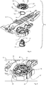
- FIG. 4 shows a perspective single-part view of the door handle support device 5 according to the invention. This comprises in addition to the frame-like door handle support 6 formed on the door handle support 6 receiving space 7 (see, for example FIGS.
- a closing device 8 of the door handle support device 5 is at least partially inserted and housed there.
- the locking device 8 for unlocking or locking a vehicle-side locking system 9 (such as a in FIG. 1 schematically indicated lock or a central lock) can be used to unlock the doors 2 or lock.
- the locking device 8 itself has a housing 10 and a cylinder core 11 rotatably mounted in the housing 10 (see, for example FIG. 4 ), which is known to comprise a keyway for receiving a key, not shown, and spring-loaded tumblers.
- a rotatably connected to the cylinder core driver element 12 is arranged, which is formed in the present embodiment, one piece with the cylinder core 11 and paddle-shaped.
- the driver element 12 serves to actuate the vehicle-side locking system 9 and is coupled thereto.
- the cylinder core 11 is rotatable by a mechanical key, so that upon rotation of the cylinder core 11, the driving element 12 coupled to the locking system 9 is rotated, the rotational movement for unlocking or locking the door 2 being transmitted to the vehicle-side locking system 9.
- the further structure of the closing device 8 is known from the prior art, so that is dispensed with a more detailed description of the individual components of the locking device 8 and their interaction at this point.
- the cylinder core 11 and thus the paddle-shaped Carrier element 12 from a basic position in the Figures 5 and 6 is shown rotated in different directions to enter an unlocked position (see for example FIG. 7 ) or locking position (see for example FIG. 8 ) to get.
- the basic position is determined by a return element 14.
- the return element 14 is formed in the embodiment shown in the figures as an annular spring element 15 with a first spring leg 15a and a second spring leg 15b, wherein the first spring leg 15a and the second spring leg 15b are spring-loaded against each other and apply the restoring force, which indirectly on the Driver element 12 acts.
- the spring element 15 is annular with several turns.
- the two legs 15a and 15b extend radially outward at different circumferential positions of the spring element 15.
- the return element 14 and the annular spring element 15 according to the present invention is not within the housing 10 of the locking device 8 and also not axially or in the longitudinal direction 16 (see for example FIG. 12 ) of the housing 10, viewed behind the cylinder core 11. Rather, the return element 14 and the spring element 15 is disposed outside of the housing 10 and radially surrounding the cylinder core 11 around, whereby the installation depth can be reduced in comparison with known devices of the prior art.
- the annular spring member 15 is disposed around the outer circumference of the cylinder core 11 around, wherein in the embodiment, the spring member 15 is additionally arranged around the outer periphery of the housing 10 around.
- the locking element 17 may be formed as a full-surface disc, but for reasons of material and weight savings recesses are provided in the present embodiment, whereby the wheel-shaped shape of the locking element 17 results.
- the Wheel-shaped locking element 17 has a central receiving opening 18, which is adapted to the contour of the paddle-shaped driver element 12.
- the locking element 17 is attached to the driver element 12, so that the driver element 12 is rotatably connected to the locking element 17, such as, for example FIG. 5 can be seen.
- a lever arm 19 Formed on the wheel-shaped locking element 17 is a lever arm 19, which extends radially beyond the peripheral edge 20 of the locking element 18 and can be coupled to the lock 9 of the motor vehicle 1 (see, for example FIG. 4 ).
- the cylinder core 11 is locked in the basic position of the driver 12 by not shown in the figures tumblers against turning. After insertion of a suitable key, the cylinder core 11 is unlocked and can be selectively rotated in one or the other direction for unlocking or locking, wherein the driver element 12 is rotated to an unlocked position or a locking position. If the key is released after rotation, then the driver element 12 and thus also the cylinder core 11 with the help of the return element 14 and the spring element 15 back into the from the Figures 5 and 6 recognizable lockable basic position. The turning back takes place automatically by the return element 14 and the spring element 15, as will be described below.
- the locking element 17 is attached to the driver element 12.
- the locking element 17 is rotatably supported on the door handle support 6 via the driver element 12.
- guide arms 21 are formed on the door handle carrier 6, which extend in the longitudinal direction 16 of the housing 10.
- the guide arms 21 are arranged around the peripheral edge 20 of the wheel-shaped locking element 17 and engage behind the peripheral edge 20 of the locking element 17 at least in the Basic position and at least during a movement from the basic position into the unlocked position or from the basic position into the locking position.
- For the wheel-shaped locking element 17 is coupled to the door handle support 6 in the manner of a bayonet connection.
- the peripheral edge 20 of the wheel-shaped locking element 17 mounting recesses 22 (see, for example FIGS. 4 and 11 ), whose number corresponds to the number of guide arms 21.
- the interaction of the mounting recesses 22 and the guide arms 21 is off FIG. 9 can be seen, in which the locking element 17 is arranged in a mounting position.
- the guide arms 21 are arranged in alignment with the mounting recesses 22, so that when mounting the locking element 17 on the door handle support 6, the guide arms 21 reach behind the peripheral edge 20 of the locking element 17 and can engage behind this.
- the guide arms 21 do not engage behind the peripheral edge 20 of the wheel-shaped locking element 17, so that the locking element 17 in the longitudinal direction 16 of the housing 10 is movable.
- the locking element 17 When the guide arms 21 engage behind the peripheral edge 20 of the locking element 17, the locking element 17 is immovable in the longitudinal direction, but rotatably held on the door handle support 6 and can be rotated to the position in which the driver element 12 can be inserted into the receiving opening 18 of the locking element 17 when the locking device 8 is mounted on the door handle support 6.
- the resetting element 14 designed as an annular spring element 15 is mounted on a side surface of the locking element 17. More specifically, the spring member 15 is mounted on the side surface of the locking member 17, which faces the locking device 8. In this case, the outer circumference of the locking element 17 is dimensioned to be larger than the outer circumference of the restoring element 14 or of the spring element 15, so that the spring element 15 viewed radially or circumferentially within the locking element 17th is arranged horizontally.
- the return element 14 is arranged between the locking element 17 and the door handle support 6.
- the locking element 15 For attaching the spring element 15 to the locking element 15, the locking element 15 has a first support arm 23 and a second support arm 24 which extend in the longitudinal direction 16 of the housing 10 and are arranged diametrically opposite one another, such as, for example Figures 10 and 14 is apparent.
- the spring element 15 is clipped with its turns in the L-shaped support arms 23 and 24 and is held in this way on the locking element 17, whereby alternative mounting options can be considered.
- the spring element 15 can apply a restoring force when the locking member 17 by rotation of the cylinder core 11 via the either in the locking position (see, for example FIG. 8 ) or in the unlocked position (see for example FIG. 7
- the spring legs 15a and 15b must be supported both at a fixed point and at a co-moving with the cylinder core 11 point.
- both spring legs 15a and 15b contact a stationary support projection 25 (see, for example, FIGS. 13 and 14 ), which is formed on the door handle support 6, wherein in the sectional view of FIG. 14 only the first spring leg 15a can be seen, as it rests against the support lug 25.
- the second spring leg 15b abuts against the other side of the support lug 25.
- the spring legs 15a and 15b bear on opposite sides of the stationary support projection 25, as in particular FIG. 13 can be seen.
- FIG. 13 is easy to see due to the omission of the locking element 17 (but the spring element 15 is in its mounted on the locking element 17 in position FIG. 13 arranged) that the spring member 15 formed as a return element 14 outside of the housing 10 and radially surrounding the housing 10 and the cylinder core 11 is arranged.
- the spring element 15 is slipped over the housing 10 and the cylinder core 11 and thereby takes no Installation space behind the longitudinal end of the locking device 8 a.
- both the first spring leg 15 a and the second spring leg 15 b respectively abut on opposite sides of a movement projection 26, which is formed on the locking element 18.
- the movement approach 26 thus forms the co-moving with rotation of the cylinder core 11 point, whereby the spring legs 15a and 15b are spread apart, whereby the restoring force is applied, which the cylinder core 11, the driver element 12 and the locking member 17 which are rotatably connected to each other, in the basic position of the driver element 12 urges when the inserted in the cylinder core 11 key is released after rotation.
- the present invention provides a door handle support device 5 which, unlike the devices known from the prior art, is characterized by a small installation depth.
- the door handle carrier device 5 described above has the restoring element 14, which according to the invention is arranged outside the housing 10 and radially surrounding the cylinder core 11.
- the ring-shaped return element 14 is arranged radially around the cylinder core 11 around.
- the low installation depth is further promoted by the wheel-shaped locking element 17, which is coupled instead of the driver 12 with the locking device 8 of the motor vehicle 1.
Landscapes
- Lock And Its Accessories (AREA)
Abstract
Description
- Die Erfindung betrifft eine Türgriffträgervorrichtung eines Kraftfahrzeugs, die einen Türgriffträger mit einem Aufnahmeraum, eine an dem Türgriffträger befestigbare Verriegelungsvorrichtung, die zumindest teilweise in dem Aufnahmeraum untergebracht ist und die wenigstens ein Gehäuse, einen im Gehäuse drehbar gelagerten Zylinderkern und ein drehfest mit dem Zylinderkern verbundenes Mitnehmerelement zum Betätigen eines Schlosses des Kraftfahrzeugs umfasst, und ein Rückstellelement, welches eine das Mitnehmerelement in eine Grundstellung haltende oder rückstellende Rückstellkraft auf das Mitnehmerelement ausübt, aufweist, wobei das Mitnehmerelement gegen die Rückstellkraft des Rückstellelements aus der Grundstellung in eine Entriegelungsstellung oder in eine Verriegelungsstellung drehbar ist.
- Eine Türgriffträgervorrichtung der eingangs bezeichneten Art ist zum Beispiel aus der
DE 10 2012 104 889 A1 bekannt, die einen Türgriffträger mit einer Öffnung beschreibt, die zur Aufnahme eines Gehäuses einer Schließvorrichtung vom Typ eines Schließzylinders dient. Eine Schließvorrichtung der eingangs bezeichneten Art ist ebenso aus dem Stand der Technik bekannt und wird in Kombination mit einem mechanischen Schlüssel zum Entriegeln und Verriegeln eines fahrzeugseitigen Schlosses verwendet. Bei dieser bekannten Schließvorrichtung ist ein Zylinderkern drehbar in dem Gehäuse gelagert, wobei der Zylinderkern drehfest mit einem Mitnehmerelement gekoppelt ist. Das Mitnehmerelement ist zur Betätigung des fahrzeugseitig eingebauten Schlosses aus einer Grundstellung in verschiedene Arbeitsstellungen überführbar, die bekanntermaßen als eine Entriegelungsstellung und eine Verriegelungsstellung bezeichnet werden. Dabei sorgt ein nach Art eines Federelements ausgebildetes Rückstellelement dafür, dass das Mitnehmerelement immer wieder in die Grundstellung zurückbewegt wird. Das Federelement ist innerhalb des Gehäuses der Schließvorrichtung untergebracht und in Verlängerung des Zylinderkerns axial hinter dem Längsende des Zylinderkerns und des Gehäuses angeordnet, was eine Vergrößerung des Einbauraumes der Schließvorrichtung und folglich der Türgriffträgervorrichtung nach sich zieht. Dies hat zur nachteiligen Folge, dass die Tiefe der Tür des Kraftfahrzeugs diese Einbautiefe berücksichtigen muss. Denn bei der Gesamttiefe der Tür, also der Erstreckung von Türaußenseite zur Türinnenseite, ist im Allgemeinen zusätzlich die Tiefe zu berücksichtigen, die benötigt wird, damit die Fensterscheibe bei Öffnung an der Türgriffträgervorrichtung vorbeigeführt werden kann. Die Tiefe zur Versenkung der Fensterscheibe ist so gut wie gar nicht zu reduzieren, so dass die Einbautiefe der Türgriffträgervorrichtung die Gesamttiefe der Tür maßgeblich bestimmt. - Der Erfindung liegt die Aufgabe zugrunde, auf konstruktiv einfache Weise und kostengünstig eine Türgriffträgervorrichtung eines Kraftfahrzeugs zu entwickeln, welche eine geringe Einbautiefe aufweist und durch welche die Gesamttiefe der Tür verringert werden kann.
- Bei einer Türgriffträgervorrichtung der eingangs bezeichneten Art wird diese Aufgabe erfindungsgemäß dadurch gelöst, dass das Rückstellelement radial umliegend um den Zylinderkern herum und außerhalb des Gehäuses angeordnet ist.
- Vorteilhafte und zweckmäßige Ausgestaltungen und Weiterbildungen der Erfindung ergeben sich aus den Unteransprüchen.
- Durch die Erfindung wird auf konstruktiv einfache Weise und kostengünstig eine Türgriffträgervorrichtung bereitgestellt, durch welche die Gesamttiefe der Tür auf ein Minimum reduziert werden kann. Während im Stand der Technik das Rückstellelement innerhalb des Gehäuses und axial hinter dem Längsende des Zylinderkerns angeordnet ist, wird diese Einbautiefe durch die Erfindung eingespart, denn das Rückstellelement ist insbesondere radial umliegend um das Gehäuse herum angeordnet, so dass erfindungsgemäß kein Einbauraum in Tiefenrichtung, d.h. axial hinter dem Längsende des Zylinderkerns, benötigt wird, sondern dieser Raum eingespart wird, so dass die Einbautiefe der Türgriffträgervorrichtung und damit die Gesamttiefe der Tür gering gehalten werden können. Dies ist erfindungsgemäß möglich, weil das Rückstellelement um den Außenumfang des Zylinderkerns herum angeordnet ist.
- In Ausgestaltung der Türgriffträgervorrichtung sieht die Erfindung vor, dass ein radförmig oder scheibenförmig ausgebildetes Verriegelungselement zum Koppeln mit dem Schloss des Kraftfahrzeugs an dem Türgriffträger drehbar gelagert ist, wobei das Mitnehmerelement drehfest mit dem radförmigen Verriegelungselement verbunden ist. Genauer gesagt ist das Mitnehmerelement in eine zentral in dem Verriegelungselement ausgebildete Aufnahme eingesteckt, wodurch die drehfeste Verbindung hergestellt ist. Dabei liegt das Verriegelungselement im Wesentlichen flächig innerhalb einer in dem Türgriffträger ausgebildeten Ausnehmung, so dass die Einbautiefe der Türgriffträgervorrichtung nicht beeinträchtigt ist. Darüber hinaus ist an dem Verriegelungselement das Rückstellelement haltend angebracht.
- Konstruktiv besonders günstig ist es dann in weiterer Ausgestaltung der Erfindung, wenn das Rückstellelement als wenigstens ein Federelement mit einem ersten Federschenkel und einem zweiten Federschenkel ausgebildet ist, wobei der erste Federschenkel und der zweite Federschenkel gegeneinander federbelastet sind und die Rückstellkraft aufbringen, welche über das Verriegelungselement auf das Mitnehmerelement wirkt.
- Die Erfindung sieht in weiterer Ausgestaltung vor, dass an dem Verriegelungselement wenigstens ein Halterungsarm angeformt ist, über den das wenigstens eine Federelement an dem Verriegelungselement gehalten ist. Das Federelement bzw. das Rückstellelement sind folglich nicht an dem Zylinderkern oder dem Türgriffträger, sondern an dem Verriegelungselement angebracht, was die Montage der Türgriffträgervorrichtung erleichtert, denn das Rückstellelement kann an dem Verriegelungselement vormontiert werden, bevor das Verriegelungselement selbst an dem Türgriffträger drehbar montiert wird.
- Die Erfindung sieht in weiterer Ausgestaltung vor, dass sich sowohl der erste Federschenkel als auch der zweite Federschenkel jeweils an einem an dem Türgriffträger ausgebildeten Abstützansatz abstützen. Der Abstützansatz dient dabei als ein konstruktiv besonders einfach auszugestaltender ortsfester Bezugspunkt.
- Damit die beiden Federschenkel gegeneinander federbelastet sein können und die Rückstellkraft aufbringen können, ist es in weiterer Ausgestaltung der Erfindung von besonderem Vorteil, wenn sowohl der erste Federschenkel als auch der zweite Federschenkel jeweils an einem an dem Verriegelungselement ausgebildeten Bewegungsansatz anliegen, so dass bei einer Bewegung des Mitnehmerelements aus der Grundstellung in die Entriegelungsstellung oder in die Verriegelungsstellung die beiden Federschenkel gegeneinander federbelastet sind und die Rückstellkraft aufbringen.
- Im Hinblick auf eine einfache und kostengünstige Konstruktion ist es in Ausgestaltung der Erfindung vorteilhaft, wenn an dem Türgriffträger wenigstens ein Führungsarm angeformt ist, welcher sich in Längsrichtung des Gehäuses erstreckt und den Umfangsrand des radförmig ausgebildeten Verriegelungselements zumindest in der Grundstellung und wenigstens bei einer Bewegung aus der Grundstellung in die Entriegelungsstellung oder in die Verriegelungsstellung hintergreift.
- Zur Erhöhung der Montagefreundlichkeit sieht die Erfindung in weiterer Ausgestaltung vor, dass der Umfangsrand des radförmig ausgebildeten Verriegelungselements zumindest eine Montageausnehmung aufweist, wobei das Verriegelungselement zur Montage an dem Türgriffträger in eine Montagestellung drehbar ist, in welcher der wenigstens eine Führungsarm mit der zumindest einen Montageausnehmung fluchtend angeordnet ist und den Umfangsrand des radförmig oder scheibenförmig ausgebildeten Verriegelungselements nicht hintergreift.
- Schließlich sieht die Erfindung in weiterer Ausgestaltung vor, dass an dem radförmig ausgebildeten Verriegelungselement ein Hebelarm angeformt ist, welcher sich radial über den Umfangsrand des Verriegelungselements hinaus erstreckt und mit dem Schloss des Kraftfahrzeugs koppelbar ist. Die gesamte Baueinheit aus Schließvorrichtung, Verriegelungselement, das auf das Mitnehmerelement der Schließvorrichtung aufgesteckt ist, und Rückstellelement, welches drehfest an dem Verriegelungselement angebracht ist und sich an dem Türgriffträger abstützt, kann mit einer geringen Einbautiefe ausgeführt werden, was durch den Hebelarm weiter unterstützt wird, der radial über den Umfangsrand des Verriegelungselements hinausragt.
- Es versteht sich, dass die vorstehend genannten und nachstehend noch zu erläuternden Merkmale nicht nur in der jeweils angegebenen Kombination, sondern auch in anderen Kombinationen oder in Alleinstellung verwendbar sind, ohne den Rahmen der vorliegenden Erfindung zu verlassen. Der Rahmen der Erfindung ist nur durch die Ansprüche definiert.
- Weitere Einzelheiten, Merkmale und Vorteile des Gegenstandes der Erfindung ergeben sich aus der nachfolgenden Beschreibung im Zusammenhang mit der Zeichnung, in der ein beispielhaftes bevorzugtes Ausführungsbeispiel der Erfindung dargestellt ist. In der Zeichnung zeigt:
-
Figur 1 eine Seitenansicht eines Kraftfahrzeugs mit einer erfindungsgemäßen Türgriffträgervorrichtung, -
Figur 2 eine perspektivische Vorderansicht auf die Türgriffträgervorrichtung gemäß der Erfindung, -
Figur 3 eine perspektivische Rückansicht auf die Türgriffträgervorrichtung gemäß der Erfindung, -
Figur 4 eine perspektivische Einzelteildarstellung der erfindungsgemäßen Türgriffträgervorrichtung, -
Figur 5 eine vergrößerte Perspektivansicht auf ein Verriegelungselement und ein in Grundstellung angeordnetes Mitnehmerelement der Türgriffträgervorrichtung, -
Figur 6 eine perspektivische Draufsicht auf das Verriegelungselement und das Mitnehmerelement in Grundstellung, -
Figur 7 eine weitere perspektivische Draufsicht auf das Verriegelungselement und das Mitnehmerelement in Entriegelungsstellung, -
Figur 8 eine noch weitere perspektivische Draufsicht auf das Verriegelungselement und das Mitnehmerelement in Verriegelungsstellung, -
Figur 9 eine weitere perspektivische Draufsicht auf das Verriegelungselement in Montagestellung, -
Figur 10 eine Perspektivansicht auf das Verriegelungselement, -
Figur 11 eine perspektivische Einzelteildarstellung von Türgriffträger und Verriegelungselement, -
Figur 12 eine seitliche Perspektivansicht auf eine Schließvorrichtung und einem Rückstellelement der Türgriffträgervorrichtung, -
Figur 13 eine perspektivische Draufsicht auf den Türgriffträger und die daran angebrachte Schließvorrichtung und die Anordnung des Rückstellelements nach Montage unter Auslassung des Verriegelungselements in dieser Ansicht und -
Figur 14 eine seitliche Schnittansicht der Türgriffträgervorrichtung. - In
Figur 1 ist ein Fahrzeug bzw. Kraftfahrzeug 1 in Form eines PKWs exemplarisch dargestellt, welches in dem Beispiel über vier Türen 2 (zwei davon sind ausFigur 1 ersichtlich) verfügt, die über eine Türgriffanordnung 3 und insbesondere mit Hilfe eines Türgriffs bzw. einer Handhabe 4 geöffnet werden können. Die Handhabe 4 ist an einer inFigur 1 nur schematisch für die Fahrertür 2 angedeuteten Türgriffträgervorrichtung 5 bewegbar gelagert. Die Türgriffträgervorrichtung 5 ist inFigur 2 in einer Vorderansicht gezeigt, wohingegen inFigur 3 eine Rückansicht der Türgriffträgervorrichtung 5 dargestellt ist. Die Türgriffträgervorrichtung 5 weist einen rahmenartigen Türgriffträger 6 auf, der bekanntermaßen der Anbringung der Handhabe 4 dient und mittels nicht näher dargestellter Schraubverbindungen an der Innenseite der Tür 2 befestigt ist, wobei die Handhabe 4 auf der Außenseite der Tür 2 angeordnet ist. Dabei ist der Türgriffträger 6 aus Gründen der Materialeinsparung überwiegend aus einer Rahmenstruktur gebildet, die über verschiedene Aufnahme- und Lagerräume verfügt, um unter anderem die Handhabe 4 aufnehmen zu können, die an dem Türgriffträger 6 zum Öffnen einer entsprechenden Tür 2 des Kraftfahrzeugs 1 durch einen Benutzer bewegbar und/oder verschwenkbar an dem Türgriffträger 6 gelagert ist.Figur 4 zeigt eine perspektivische Einzelteildarstellung der erfindungsgemäßen Türgriffträgervorrichtung 5. Diese umfasst zusätzlich zu dem rahmenartig ausgebildeten Türgriffträger 6 einen am Türgriffträger 6 ausgebildeten Aufnahmeraum 7 (siehe zum BeispielFiguren 4 und11 ), in dem eine Schließvorrichtung 8 der Türgriffträgervorrichtung 5 zumindest teilweise eingesteckt und dort untergebracht ist. Mit Hilfe eines mechanischen Schlüssels kann die Schließvorrichtung 8 zum Entriegeln oder Verriegeln eines fahrzeugseitigen Schließsystems 9 (wie zum Beispiel ein inFigur 1 schematisch angedeutetes Schloss oder eine Zentralverriegelung) verwendet werden, um die Türen 2 entriegeln oder verriegeln zu können. Die Schließvorrichtung 8 selbst weist ein Gehäuse 10 und ein drehbar in dem Gehäuse 10 gelagerten Zylinderkern 11 auf (siehe zum BeispielFigur 4 ), der bekanntermaßen einen Schlüsselkanal zur Aufnahme eines nicht näher dargestellten Schlüssels und federbelastete Zuhaltungen umfasst. An der der Öffnung des Schlüsselkanals abgewandten Längsseite des Zylinderkerns 11 ist ein drehfest mit dem Zylinderkern verbundenes Mitnehmerelement 12 angeordnet, was in dem vorliegenden Ausführungsbeispiel einstückig mit dem Zylinderkern 11 und paddelförmig ausgebildet ist. Das Mitnehmerelement 12 dient zur Betätigung des fahrzeugseitigen Schließsystems 9 und ist mit diesem gekoppelt. Der Zylinderkern 11 ist von einem mechanischen Schlüssel drehbar, so dass bei einer Drehbewegung des Zylinderkerns 11 das mit dem Schließsystem 9 gekoppelte Mitnehmerelement 12 gedreht wird, wobei die Drehbewegung zum Entsperren bzw. Verriegeln der Tür 2 auf das kraftfahrzeugseitige Schließsystem 9 übertragen wird. Der weitere Aufbau der Schließvorrichtung 8 ist aus dem Stand der Technik bekannt, so dass auf eine detailliertere Beschreibung der einzelnen Bauteile der Schließvorrichtung 8 und deren Zusammenwirken an dieser Stelle verzichtet wird. - Zum Verriegeln oder Entriegeln wird folglich der Zylinderkern 11 und damit das paddelförmig ausgebildete Mitnehmerelement 12 aus einer Grundstellung, die in den
Figuren 5 und6 gezeigt ist, in unterschiedliche Richtungen gedreht, um in eine Entriegelungsstellung (siehe zum BeispielFigur 7 ) oder Verriegelungsstellung (siehe zum BeispielFigur 8 ) zu gelangen. Dabei wird die Grundstellung durch ein Rückstellelement 14 bestimmt. Das Rückstellelement 14 ist in dem in den Figuren dargestellten Ausführungsbeispiel als ein ringförmiges Federelement 15 mit einem ersten Federschenkel 15a und einem zweiten Federschenkel 15b ausgebildet, wobei der erste Federschenkel 15a und der zweite Federschenkel 15b gegeneinander federbelastet sind und die Rückstellkraft aufbringen, welche indirekt auf das Mitnehmerelement 12 wirkt. Das Federelement 15 ist dabei mit mehreren Windungen ringförmig ausgebildet. Die beiden Schenkel 15a und 15b erstrecken sich radial auswärts an unterschiedlichen Umfangspositionen des Federelements 15. Im Unterschied zum Stand der Technik ist das Rückstellelement 14 bzw. das ringförmige Federelement 15 gemäß der vorliegenden Erfindung nicht innerhalb des Gehäuses 10 der Schließvorrichtung 8 und auch nicht axial bzw. in Längsrichtung 16 (siehe zum BeispielFigur 12 ) des Gehäuses 10 betrachtet hinter dem Zylinderkern 11 angeordnet. Vielmehr ist das Rückstellelement 14 bzw. das Federelement 15 außerhalb des Gehäuses 10 und radial umliegend um den Zylinderkern 11 herum angeordnet, wodurch die Einbautiefe im Vergleich mit bekannten Vorrichtungen aus dem Stand der Technik reduziert werden kann. Genauer gesagt ist das ringförmige Federelement 15 um den Außenumfang des Zylinderkerns 11 herum angeordnet, wobei in dem Ausführungsbeispiel das Federelement 15 zusätzlich auch um den Außenumfang des Gehäuses 10 herum angeordnet ist. Zur weiteren Reduzierung der Einbautiefe ist das Mitnehmerelement 12 nicht wie im Stand der Technik mit einem auskragenden Verriegelungszapfen gekoppelt, sondern mit einem radförmig ausgebildeten Verriegelungselement 17. Alternativ könnte das Verriegelungselement 17 auch als vollflächige Scheibe ausgebildet sein, wobei aber aus Gründen der Material- und Gewichtseinsparung in dem vorliegenden Ausführungsbeispiel Aussparungen vorgesehen sind, wodurch sich die radförmige Gestalt des Verriegelungselements 17 ergibt. Das radförmig ausgebildete Verriegelungselement 17 weist eine zentrale Aufnahmeöffnung 18 auf, die an die Kontur des paddelförmigen Mitnehmerelements 12 angepasst ist. Das Verriegelungselement 17 ist auf das Mitnehmerelement 12 aufgesteckt, so dass das Mitnehmerelement 12 drehfest mit dem Verriegelungselement 17 verbunden ist, wie beispielsweise ausFigur 5 zu erkennen ist. An dem radförmig ausgebildeten Verriegelungselement 17 ist ein Hebelarm 19 angeformt, welcher sich radial über den Umfangsrand 20 des Verriegelungselements 18 hinaus erstreckt und mit dem Schloss 9 des Kraftfahrzeugs 1 koppelbar ist (siehe zum BeispielFigur 4 ). - Zur grundlegenden Funktion der Schließvorrichtung 8 sei folgendes angemerkt. Der Zylinderkern 11 ist in der Grundstellung des Mitnehmerelements 12 durch in den Figuren nicht näher dargestellte Zuhaltungen gegen Drehen gesperrt. Nach Einführung eines passenden Schlüssels ist der Zylinderkern 11 entsperrt und kann wahlweise in die eine oder andere Richtung zum Entriegeln oder Verriegeln gedreht werden, wobei das Mitnehmerelement 12 in eine Entriegelungsstellung oder eine Verriegelungsstellung gedreht wird. Wird der Schlüssel nach Drehung losgelassen, so stellt sich das Mitnehmerelement 12 und damit auch der Zylinderkern 11 mit Hilfe des Rückstellelements 14 bzw. des Federelements 15 wieder in die aus den
Figuren 5 und6 erkennbare sperrbare Grundstellung ein. Das Zurückdrehen erfolgt selbsttätig durch das Rückstellelement 14 bzw. das Federelement 15, wie nachstehend noch beschrieben wird. - Wie vorstehend ausgeführt, ist das Verriegelungselement 17 auf das Mitnehmerelement 12 aufgesteckt. Zusätzlich ist das Verriegelungselement 17 über das Mitnehmerelement 12 drehbar an dem Türgriffträger 6 gelagert. Damit das Verriegelungselement 12 sich nicht aus der mit dem Mitnehmerelement 12 gebildeten drehfesten Steckverbindung lösen kann, sind an dem Türgriffträger 6 Führungsarme 21 angeformt, welche sich in Längsrichtung 16 des Gehäuses 10 erstrecken. Die Führungsarme 21 sind um den Umfangsrand 20 des radförmig ausgebildeten Verriegelungselements 17 angeordnet und hintergreifen den Umfangsrand 20 des Verriegelungselements 17 zumindest in der Grundstellung und wenigstens bei einer Bewegung aus der Grundstellung in die Entriegelungsstellung oder aus der Grundstellung in die Verriegelungsstellung. Denn das radförmige Verriegelungselement 17 ist nach Art einer Bajonettverbindung mit dem Türgriffträger 6 gekoppelt. Zu diesem Zweck weist der Umfangsrand 20 des radförmig ausgebildeten Verriegelungselements 17 Montageausnehmungen 22 auf (siehe zum Beispiel
Figuren 4 und11 ), deren Anzahl zu der Anzahl der Führungsarme 21 korrespondiert. Das Zusammenspiel der Montageausnehmungen 22 und der Führungsarme 21 wird ausFigur 9 ersichtlich, in welcher das Verriegelungselement 17 in einer Montagestellung angeordnet ist. In der Montagestellung sind die Führungsarme 21 fluchtend zu den Montageausnehmungen 22 angeordnet, so dass bei Montage des Verriegelungselements 17 an dem Türgriffträger 6 die Führungsarme 21 hinter den Umfangsrand 20 des Verriegelungselements 17 gelangen und diesen hintergreifen können. In der Montagestellung des Verriegelungselements 17 hintergreifen die Führungsarme 21 nicht den Umfangsrand 20 des radförmig ausgebildeten Verriegelungselements 17, so dass das Verriegelungselement 17 in Längsrichtung 16 des Gehäuses 10 bewegbar ist. Wenn die Führungsarme 21 den Umfangsrand 20 des Verriegelungselements 17 hintergreifen, dann ist das Verriegelungselement 17 in Längsrichtung unbeweglich, aber drehbar am Türgriffträger 6 gehalten und kann in die Stellung gedreht werden, in welcher das Mitnehmerelement 12 in die Aufnahmeöffnung 18 des Verriegelungselements 17 eingesteckt werden kann, wenn die Schließvorrichtung 8 am Türgriffträger 6 montiert wird. - Das als ringförmiges Federelement 15 ausgebildete Rückstellelement 14 ist auf einer Seitenfläche des Verriegelungselements 17 angebracht. Genauer gesagt ist das Federelement 15 auf der Seitenfläche des Verriegelungselements 17 angebracht, die der Schließvorrichtung 8 zugewandt ist. Dabei ist der Außenumfang des Verriegelungselements 17 größer bemessen als der Außenumfang des Rückstellelements 14 bzw. des Federelements 15, so dass das Federelement 15 radial oder umfangsmäßig betrachtet innerhalb des Verriegelungselements 17 liegend angeordnet ist. Das Rückstellelement 14 ist zwischen dem Verriegelungselement 17 und dem Türgriffträger 6 angeordnet. Zur Anbringung des Federelements 15 an dem Verriegelungselement 15 weist das Verriegelungselement 15 einen ersten Halterungsarm 23 und einen zweiten Halterungsarm 24 auf, die sich in Längsrichtung 16 des Gehäuses 10 erstrecken und diametral zueinander angeordnet sind, wie zum Beispiel aus den
Figuren 10 und14 ersichtlich ist. Das Federelement 15 wird mit seinen Windungen in die L-förmig ausgebildeten Halterungsarme 23 und 24 eingeclipst und ist auf diese Weise an dem Verriegelungselement 17 gehalten, wobei auch alternative Halterungsmöglichkeiten in Betracht kommen können. - Damit das Federelement 15 eine Rückstellkraft aufbringen kann, wenn das Verriegelungselement 17 durch Drehung des Zylinderkerns 11 über das entweder in die Verriegelungsstellung (siehe zum Beispiel
Figur 8 ) oder in die Entriegelungsstellung (siehe zum BeispielFigur 7 ) bewegte Mitnehmerelement 12 verdreht wird, müssen sich die Federschenkel 15a und 15b sowohl an einem ortsfesten Punkt als auch an einem mit dem Zylinderkern 11 mitbewegten Punkt abstützen können. In der Grundstellung liegen beide Federschenkel 15a und 15b an einem ortsfesten Abstützansatz 25 an (siehe zum BeispielFiguren 13 und 14 ), der an dem Türgriffträger 6 ausgebildet ist, wobei in der Schnittansicht derFigur 14 nur der erste Federschenkel 15a zu sehen ist, wie er an dem Abstützansatz 25 anliegt. Der zweite Federschenkel 15b liegt an der anderen Seite des Abstützansatzes 25 an. Somit liegen die Federschenkel 15a und 15b an entgegengesetzten Seiten des ortsfesten Abstützansatzes 25 an, wie insbesondere ausFigur 13 zu erkennen ist. InFigur 13 ist aufgrund der Auslassung des Verriegelungselements 17 gut zu sehen (das Federelement 15 ist aber in seiner an dem Verriegelungselement 17 angebrachten Position inFigur 13 angeordnet), dass das als Federelement 15 ausgebildete Rückstellelement 14 außerhalb des Gehäuses 10 und radial umliegend um das Gehäuse 10 und den Zylinderkern 11 angeordnet ist. Insbesondere ist das Federelement 15 über das Gehäuse 10 und den Zylinderkern 11 gestülpt und nimmt dadurch keinen Bauraum hinter dem Längsende der Schließvorrichtung 8 ein. Darüber hinaus liegen in der Grundstellung des Mitnehmerelements 12 sowohl der erste Federschenkel 15a als auch der zweite Federschenkel 15b jeweils an gegenüberliegenden Seiten eines Bewegungsansatzes 26 an, der an dem Verriegelungselement 18 ausgebildet ist. Der Bewegungsansatz 26 bildet folglich den bei Drehung des Zylinderkerns 11 mitbewegten Punkt, wodurch die Federschenkel 15a und 15b zueinander gespreizt werden, wodurch die Rückstellkraft aufgebracht wird, welche den Zylinderkern 11, das Mitnehmerelement 12 und das Verriegelungselement 17, die drehfest miteinander verbunden sind, in die Grundstellung des Mitnehmerelements 12 drängt, wenn der in dem Zylinderkern 11 eingesteckte Schlüssel nach Drehung losgelassen wird. Folglich sind bei einer Bewegung des Mitnehmerelements 12 aus der Grundstellung in die Entriegelungsstellung oder in die Verriegelungsstellung die beiden Federschenkel 15a, 15b gegeneinander federbelastet und bringen dadurch die gewünschte Rückstellkraft auf, um das Mitnehmerelement 12 und damit den Zylinderkern 11 wieder in die Grundstellung zu bewegen. - Zusammenfassend wird durch die vorliegende Erfindung eine Türgriffträgervorrichtung 5 zur Verfügung gestellt, die sich im Unterschied zu den aus dem Stand der Technik bekannten Vorrichtungen durch eine geringe Einbautiefe auszeichnet. Die vorstehend beschriebene Türgriffträgervorrichtung 5 weist zu diesem Zweck das Rückstellelement 14 auf, welches erfindungsgemäß außerhalb des Gehäuses 10 und radial umliegend um den Zylinderkern 11 herum angeordnet ist. Insbesondere ist das ringförmig ausgebildete Rückstellelement 14 radial um den Zylinderkern 11 herum angeordnet. Die geringe Einbautiefe wird ferner durch das radförmig ausgebildete Verriegelungselement 17 begünstigt, welches statt des Mitnehmers 12 mit der Schließvorrichtung 8 des Kraftfahrzeugs 1 gekoppelt ist.
- Die vorstehend beschriebene Erfindung ist selbstverständlich nicht auf die beschriebene und dargestellte Ausführungsform beschränkt. Es ist ersichtlich, dass an der in der Zeichnung dargestellten Ausführungsform zahlreiche, dem Fachmann entsprechend der beabsichtigten Anwendung naheliegende Abänderungen vorgenommen werden können, ohne dass dadurch der Bereich der Erfindung verlassen wird. So können beispielsweise auch eine von der in dem Ausführungsbeispiel abweichende Anzahl von Federelementen, Bewegungsansätzen, Führungsarme und Halterungsarme bei alternativen Abwandlungen des beschriebenen Ausführungsbeispiels vorgesehen werden. Zur Erfindung gehört alles dasjenige, was in der Beschreibung enthalten und/oder in der Zeichnung dargestellt ist, einschließlich dessen, was abweichend von dem konkreten Ausführungsbeispiel für den Fachmann naheliegt.
Claims (9)
- Türgriffträgervorrichtung (5) eines Kraftfahrzeugs (1), die aufweist:einen Türgriffträger (6) mit einem Aufnahmeraum (7),eine an dem Türgriffträger (6) befestigbare Schließvorrichtung (8), die zumindest teilweise in dem Aufnahmeraum (7) untergebracht ist und die wenigstens ein Gehäuse (10), einen im Gehäuse (10) drehbar gelagerten Zylinderkern (11) und ein drehfest mit dem Zylinderkern (11) verbundenes Mitnehmerelement (12) zum Betätigen eines Schlosses (9) des Kraftfahrzeugs (1) umfasst, undein Rückstellelement (14), welches eine das Mitnehmerelement (12) in eine Grundstellung haltende oder rückstellende Rückstellkraft auf das Mitnehmerelement (12) ausübt,wobei das Mitnehmerelement (12) gegen die Rückstellkraft des Rückstellelements (14) aus der Grundstellung in eine Entriegelungsstellung oder in eine Verriegelungsstellung drehbar ist,
dadurch gekennzeichnet, dass
das Rückstellelement (14) radial umliegend um den Zylinderkern (11) und außerhalb des Gehäuses (10) angeordnet ist. - Türgriffträgervorrichtung (5) nach Anspruch 1, dadurch gekennzeichnet, dass ein radförmig ausgebildetes Verriegelungselement (17) zum Koppeln mit dem Schloss (9) des Kraftfahrzeugs (1) an dem Türgriffträger (6) drehbar gelagert ist, wobei das Mitnehmerelement (12) drehfest mit dem radförmigen Verriegelungselement (17) verbunden ist.
- Türgriffträgervorrichtung (5) nach Anspruch 2, dadurch gekennzeichnet, dass das Rückstellelement (14) als wenigstens ein Federelement (15) mit einem ersten Federschenkel (15a) und einem zweiten Federschenkel (15b) ausgebildet ist, wobei der erste Federschenkel (15a) und der zweite Federschenkel (15b) gegeneinander federbelastet sind und die Rückstellkraft aufbringen, welche über das Verriegelungselement (17) auf das Mitnehmerelement (12) wirkt.
- Türgriffträgervorrichtung (5) nach Anspruch 3, dadurch gekennzeichnet, dass an dem Verriegelungselement (17) wenigstens ein Halterungsarm (23, 24) angeformt ist, über den das wenigstens eine Federelement (15) an dem Verriegelungselement (18) gehalten ist.
- Türgriffträgervorrichtung (5) nach Anspruch 3 oder 4, dadurch gekennzeichnet, dass sich sowohl der erste Federschenkel (15a) als auch der zweite Federschenkel (15b) jeweils an einem an dem Türgriffträger (6) ausgebildeten Abstützansatz (25) abstützen.
- Türgriffträgervorrichtung (5) nach einem der Ansprüche 3 bis 5, dadurch gekennzeichnet, dass sowohl der erste Federschenkel (15a) als auch der zweite Federschenkel (15b) jeweils an einem an dem Verriegelungselement (17) ausgebildeten Bewegungsansatz (26) anliegen, so dass bei einer Bewegung des Mitnehmerelements (12) aus der Grundstellung in die Entriegelungsstellung oder in die Verriegelungsstellung die beiden Federschenkel (15a, 15b) gegeneinander federbelastet sind und die Rückstellkraft aufbringen.
- Türgriffträgervorrichtung (5) nach einem der Ansprüche 2 bis 6, dadurch gekennzeichnet, dass an dem Türgriffträger (6) wenigstens ein Führungsarm (21) angeformt ist, welcher sich in Längsrichtung (16) des Gehäuses (10) erstreckt und den Umfangsrand (20) des radförmig ausgebildeten Verriegelungselements (17) zumindest in der Grundstellung und wenigstens bei einer Bewegung aus der Grundstellung in die Entriegelungsstellung oder in die Verriegelungsstellung hintergreift.
- Türgriffträgervorrichtung (5) nach Anspruch 7, dadurch gekennzeichnet, dass der Umfangsrand (20) des radförmig ausgebildeten Verriegelungselements (17) zumindest eine Montageausnehmung (22) aufweist, wobei das Verriegelungselement (17) zur Montage an dem Türgriffträger (6) in eine Montagestellung drehbar ist, in welcher der wenigstens eine Führungsarm (21) mit der zumindest einen Montageausnehmung (22) fluchtend angeordnet ist und den Umfangsrand (20) des radförmig ausgebildeten Verriegelungselements (17) nicht hintergreift.
- Türgriffträgervorrichtung (5) nach einem der Ansprüche 2 bis 8, dadurch gekennzeichnet, dass an dem radförmig ausgebildeten Verriegelungselement (17) ein Hebelarm (19) angeformt ist, welcher sich radial über den Umfangsrand (20) des Verriegelungselements (17) hinaus erstreckt und mit dem Schloss (9) des Kraftfahrzeugs (1) koppelbar ist.
Applications Claiming Priority (1)
| Application Number | Priority Date | Filing Date | Title |
|---|---|---|---|
| US201662278129P | 2016-01-13 | 2016-01-13 |
Publications (2)
| Publication Number | Publication Date |
|---|---|
| EP3192953A1 true EP3192953A1 (de) | 2017-07-19 |
| EP3192953B1 EP3192953B1 (de) | 2019-10-30 |
Family
ID=57460423
Family Applications (1)
| Application Number | Title | Priority Date | Filing Date |
|---|---|---|---|
| EP16201725.5A Not-in-force EP3192953B1 (de) | 2016-01-13 | 2016-12-01 | Türgriffträgervorrichtung eines kraftfahrzeugs |
Country Status (3)
| Country | Link |
|---|---|
| US (1) | US10253532B2 (de) |
| EP (1) | EP3192953B1 (de) |
| CN (1) | CN106968532B (de) |
Cited By (1)
| Publication number | Priority date | Publication date | Assignee | Title |
|---|---|---|---|---|
| DE102017128465A1 (de) * | 2017-10-26 | 2019-05-02 | Arndt Nicolaisen | Befestigungsmechanismus zur Sicherung eines Schließzylinders oder einer Verschlusskappe |
Families Citing this family (1)
| Publication number | Priority date | Publication date | Assignee | Title |
|---|---|---|---|---|
| DE102016110201A1 (de) * | 2016-06-02 | 2017-12-07 | BROSE SCHLIEßSYSTEME GMBH & CO. KG | Kraftfahrzeugschloss |
Citations (7)
| Publication number | Priority date | Publication date | Assignee | Title |
|---|---|---|---|---|
| DE2656011A1 (de) * | 1976-12-10 | 1978-06-29 | Bayerische Motoren Werke Ag | Kraftfahrzeugtuer mit aussengriff |
| US5285667A (en) * | 1990-11-30 | 1994-02-15 | Alpha Corporation | Cylinder lock |
| EP0646688A1 (de) * | 1993-10-05 | 1995-04-05 | YMOS AKTIENGESELLSCHAFT Industrieprodukte | Aussengriffanordnung für eine Tür, insbesondere eine Kraftfahrzeugtür |
| EP1191170A1 (de) * | 2000-09-21 | 2002-03-27 | Valeo Sicherheitssysteme GmbH | Schliessvorrichtung für eine Fahrzeugtür |
| DE10322387A1 (de) * | 2003-05-17 | 2004-12-02 | Huf Hülsbeck & Fürst Gmbh & Co. Kg | Schließeinrichtung für Türen oder Klappen von Fahrzeugen |
| JP2009270347A (ja) * | 2008-05-08 | 2009-11-19 | Yuhshin Co Ltd | シリンダ錠 |
| DE102012104889A1 (de) | 2012-06-05 | 2013-12-05 | Huf Hülsbeck & Fürst Gmbh & Co. Kg | Türaußengriffvorrichtung |
Family Cites Families (9)
| Publication number | Priority date | Publication date | Assignee | Title |
|---|---|---|---|---|
| CN86204665U (zh) * | 1986-09-25 | 1987-09-02 | 郑汉锦 | 自动安全门锁 |
| DE19826778A1 (de) * | 1998-06-11 | 1999-12-23 | Brose Fahrzeugteile | Vorrichtung zum Verbinden eines Außengriffs mit einem Schließsystem |
| US6463774B2 (en) * | 2000-05-17 | 2002-10-15 | Southco, Inc. | Push lock |
| JP4926875B2 (ja) * | 2007-07-30 | 2012-05-09 | 株式会社東海理化電機製作所 | シリンダ錠、クラッチ装置、及びこれらシリンダ錠,クラッチ装置を備えた解錠装置 |
| US8474290B2 (en) * | 2009-12-03 | 2013-07-02 | Pioptima, Inc. | Locking handle and power module assembly |
| DE102013016607B4 (de) * | 2013-10-07 | 2017-05-04 | D. la Porte Söhne GmbH | Ziehgriff für eine Fahrzeugtür |
| DE102013016606B4 (de) * | 2013-10-07 | 2017-05-24 | D. la Porte Söhne GmbH | Ziehgriff für eine Fahrzeugtür |
| DE102014107406A1 (de) * | 2014-05-26 | 2015-11-26 | Huf Hülsbeck & Fürst Gmbh & Co. Kg | Türgriffanordnung für ein Kraftfahrzeug |
| JP6096715B2 (ja) * | 2014-06-02 | 2017-03-15 | 株式会社東海理化電機製作所 | シリンダ錠装置 |
-
2016
- 2016-12-01 EP EP16201725.5A patent/EP3192953B1/de not_active Not-in-force
-
2017
- 2017-01-03 US US15/397,279 patent/US10253532B2/en not_active Expired - Fee Related
- 2017-01-09 CN CN201710013877.8A patent/CN106968532B/zh not_active Expired - Fee Related
Patent Citations (7)
| Publication number | Priority date | Publication date | Assignee | Title |
|---|---|---|---|---|
| DE2656011A1 (de) * | 1976-12-10 | 1978-06-29 | Bayerische Motoren Werke Ag | Kraftfahrzeugtuer mit aussengriff |
| US5285667A (en) * | 1990-11-30 | 1994-02-15 | Alpha Corporation | Cylinder lock |
| EP0646688A1 (de) * | 1993-10-05 | 1995-04-05 | YMOS AKTIENGESELLSCHAFT Industrieprodukte | Aussengriffanordnung für eine Tür, insbesondere eine Kraftfahrzeugtür |
| EP1191170A1 (de) * | 2000-09-21 | 2002-03-27 | Valeo Sicherheitssysteme GmbH | Schliessvorrichtung für eine Fahrzeugtür |
| DE10322387A1 (de) * | 2003-05-17 | 2004-12-02 | Huf Hülsbeck & Fürst Gmbh & Co. Kg | Schließeinrichtung für Türen oder Klappen von Fahrzeugen |
| JP2009270347A (ja) * | 2008-05-08 | 2009-11-19 | Yuhshin Co Ltd | シリンダ錠 |
| DE102012104889A1 (de) | 2012-06-05 | 2013-12-05 | Huf Hülsbeck & Fürst Gmbh & Co. Kg | Türaußengriffvorrichtung |
Cited By (1)
| Publication number | Priority date | Publication date | Assignee | Title |
|---|---|---|---|---|
| DE102017128465A1 (de) * | 2017-10-26 | 2019-05-02 | Arndt Nicolaisen | Befestigungsmechanismus zur Sicherung eines Schließzylinders oder einer Verschlusskappe |
Also Published As
| Publication number | Publication date |
|---|---|
| EP3192953B1 (de) | 2019-10-30 |
| CN106968532B (zh) | 2020-05-15 |
| CN106968532A (zh) | 2017-07-21 |
| US10253532B2 (en) | 2019-04-09 |
| US20170198505A1 (en) | 2017-07-13 |
Similar Documents
| Publication | Publication Date | Title |
|---|---|---|
| EP1727953A2 (de) | Schloss, insbesondere für fahrzeugtüren, -klappen oder dergleichen | |
| EP3022081B1 (de) | Verriegelungsvorrichtung | |
| DE102010000158B4 (de) | Sperreinrichtung für handbetätigte hintere Fahrzeugfenster, Handkurbel mit Sperreinrichtung und Fahrzeug damit | |
| EP2291569B1 (de) | Schliessvorrichtung mit einem gesperre umfassend zwei sperrklinken | |
| DE102020201152A1 (de) | Türschließsystem | |
| DE3827418A1 (de) | Schliesszylinder | |
| WO2020048653A1 (de) | Türgriffanordnung für ein kraftfahrzeug | |
| EP3192953B1 (de) | Türgriffträgervorrichtung eines kraftfahrzeugs | |
| DE60111004T2 (de) | Stellantrieb | |
| DE202007000380U1 (de) | Rückholfedereinrichtung für Tür- oder Fensterbeschläge sowie Tür- und/oder Fensterbeschlag | |
| EP2993090B2 (de) | Lenkradverriegelung | |
| DE102016219339A1 (de) | Armauflagenvorrichtung für ein Kraftfahrzeug | |
| DE4210403C2 (de) | Deckelverriegelungsvorrichtung | |
| DE102015121272A1 (de) | Türgriffanordnung eines Kraftfahrzeugs | |
| DE2000381A1 (de) | Zylinderschloss | |
| EP3803006B1 (de) | Türgriffanordnung für ein kraftfahrzeug | |
| DE102022103378A1 (de) | Fahrzeugsitzbeschlag-Entriegelungsbaugruppe, Fahrzeugsitzbeschlag und Fahrzeugsitz | |
| DE19922452B4 (de) | Als Abdeckelement an Fahrzeugen dienender beweglicher Karosserieteil | |
| DE102016215806A1 (de) | Rückenlehnenanordnung für ein Kraftfahrzeug, Kraftfahrzeug | |
| DE102017116664B4 (de) | Fahrzeug-ablagefach | |
| EP3059126B1 (de) | Anordnung für ein fahrzeug | |
| DE202018103450U1 (de) | Schnellmontage-Toilettensitzabdeckung | |
| DE4233029C2 (de) | Schließzylinder | |
| DE60016150T2 (de) | Schlüsseleinheit für eine Fahrzeugtür | |
| DE102010015684B4 (de) | Schließzylinder, insbesondere für Türschlösser von Kraftfahrzeugen |
Legal Events
| Date | Code | Title | Description |
|---|---|---|---|
| PUAI | Public reference made under article 153(3) epc to a published international application that has entered the european phase |
Free format text: ORIGINAL CODE: 0009012 |
|
| STAA | Information on the status of an ep patent application or granted ep patent |
Free format text: STATUS: THE APPLICATION HAS BEEN PUBLISHED |
|
| AK | Designated contracting states |
Kind code of ref document: A1 Designated state(s): AL AT BE BG CH CY CZ DE DK EE ES FI FR GB GR HR HU IE IS IT LI LT LU LV MC MK MT NL NO PL PT RO RS SE SI SK SM TR |
|
| AX | Request for extension of the european patent |
Extension state: BA ME |
|
| STAA | Information on the status of an ep patent application or granted ep patent |
Free format text: STATUS: REQUEST FOR EXAMINATION WAS MADE |
|
| 17P | Request for examination filed |
Effective date: 20180119 |
|
| RBV | Designated contracting states (corrected) |
Designated state(s): AL AT BE BG CH CY CZ DE DK EE ES FI FR GB GR HR HU IE IS IT LI LT LU LV MC MK MT NL NO PL PT RO RS SE SI SK SM TR |
|
| GRAP | Despatch of communication of intention to grant a patent |
Free format text: ORIGINAL CODE: EPIDOSNIGR1 |
|
| STAA | Information on the status of an ep patent application or granted ep patent |
Free format text: STATUS: GRANT OF PATENT IS INTENDED |
|
| RIC1 | Information provided on ipc code assigned before grant |
Ipc: E05B 79/06 20140101ALI20190625BHEP Ipc: E05B 15/04 20060101ALN20190625BHEP Ipc: E05B 9/04 20060101ALN20190625BHEP Ipc: E05B 85/06 20140101AFI20190625BHEP |
|
| INTG | Intention to grant announced |
Effective date: 20190718 |
|
| GRAS | Grant fee paid |
Free format text: ORIGINAL CODE: EPIDOSNIGR3 |
|
| GRAA | (expected) grant |
Free format text: ORIGINAL CODE: 0009210 |
|
| STAA | Information on the status of an ep patent application or granted ep patent |
Free format text: STATUS: THE PATENT HAS BEEN GRANTED |
|
| AK | Designated contracting states |
Kind code of ref document: B1 Designated state(s): AL AT BE BG CH CY CZ DE DK EE ES FI FR GB GR HR HU IE IS IT LI LT LU LV MC MK MT NL NO PL PT RO RS SE SI SK SM TR |
|
| REG | Reference to a national code |
Ref country code: GB Ref legal event code: FG4D Free format text: NOT ENGLISH |
|
| REG | Reference to a national code |
Ref country code: CH Ref legal event code: EP |
|
| REG | Reference to a national code |
Ref country code: AT Ref legal event code: REF Ref document number: 1196300 Country of ref document: AT Kind code of ref document: T Effective date: 20191115 |
|
| REG | Reference to a national code |
Ref country code: DE Ref legal event code: R096 Ref document number: 502016007294 Country of ref document: DE |
|
| REG | Reference to a national code |
Ref country code: IE Ref legal event code: FG4D Free format text: LANGUAGE OF EP DOCUMENT: GERMAN |
|
| REG | Reference to a national code |
Ref country code: LT Ref legal event code: MG4D |
|
| PG25 | Lapsed in a contracting state [announced via postgrant information from national office to epo] |
Ref country code: BG Free format text: LAPSE BECAUSE OF FAILURE TO SUBMIT A TRANSLATION OF THE DESCRIPTION OR TO PAY THE FEE WITHIN THE PRESCRIBED TIME-LIMIT Effective date: 20200130 Ref country code: FI Free format text: LAPSE BECAUSE OF FAILURE TO SUBMIT A TRANSLATION OF THE DESCRIPTION OR TO PAY THE FEE WITHIN THE PRESCRIBED TIME-LIMIT Effective date: 20191030 Ref country code: PL Free format text: LAPSE BECAUSE OF FAILURE TO SUBMIT A TRANSLATION OF THE DESCRIPTION OR TO PAY THE FEE WITHIN THE PRESCRIBED TIME-LIMIT Effective date: 20191030 Ref country code: LT Free format text: LAPSE BECAUSE OF FAILURE TO SUBMIT A TRANSLATION OF THE DESCRIPTION OR TO PAY THE FEE WITHIN THE PRESCRIBED TIME-LIMIT Effective date: 20191030 Ref country code: GR Free format text: LAPSE BECAUSE OF FAILURE TO SUBMIT A TRANSLATION OF THE DESCRIPTION OR TO PAY THE FEE WITHIN THE PRESCRIBED TIME-LIMIT Effective date: 20200131 Ref country code: NO Free format text: LAPSE BECAUSE OF FAILURE TO SUBMIT A TRANSLATION OF THE DESCRIPTION OR TO PAY THE FEE WITHIN THE PRESCRIBED TIME-LIMIT Effective date: 20200130 Ref country code: LV Free format text: LAPSE BECAUSE OF FAILURE TO SUBMIT A TRANSLATION OF THE DESCRIPTION OR TO PAY THE FEE WITHIN THE PRESCRIBED TIME-LIMIT Effective date: 20191030 Ref country code: SE Free format text: LAPSE BECAUSE OF FAILURE TO SUBMIT A TRANSLATION OF THE DESCRIPTION OR TO PAY THE FEE WITHIN THE PRESCRIBED TIME-LIMIT Effective date: 20191030 Ref country code: NL Free format text: LAPSE BECAUSE OF FAILURE TO SUBMIT A TRANSLATION OF THE DESCRIPTION OR TO PAY THE FEE WITHIN THE PRESCRIBED TIME-LIMIT Effective date: 20191030 Ref country code: PT Free format text: LAPSE BECAUSE OF FAILURE TO SUBMIT A TRANSLATION OF THE DESCRIPTION OR TO PAY THE FEE WITHIN THE PRESCRIBED TIME-LIMIT Effective date: 20200302 |
|
| REG | Reference to a national code |
Ref country code: NL Ref legal event code: MP Effective date: 20191030 |
|
| PG25 | Lapsed in a contracting state [announced via postgrant information from national office to epo] |
Ref country code: RS Free format text: LAPSE BECAUSE OF FAILURE TO SUBMIT A TRANSLATION OF THE DESCRIPTION OR TO PAY THE FEE WITHIN THE PRESCRIBED TIME-LIMIT Effective date: 20191030 Ref country code: HR Free format text: LAPSE BECAUSE OF FAILURE TO SUBMIT A TRANSLATION OF THE DESCRIPTION OR TO PAY THE FEE WITHIN THE PRESCRIBED TIME-LIMIT Effective date: 20191030 Ref country code: IS Free format text: LAPSE BECAUSE OF FAILURE TO SUBMIT A TRANSLATION OF THE DESCRIPTION OR TO PAY THE FEE WITHIN THE PRESCRIBED TIME-LIMIT Effective date: 20200229 |
|
| PG25 | Lapsed in a contracting state [announced via postgrant information from national office to epo] |
Ref country code: AL Free format text: LAPSE BECAUSE OF FAILURE TO SUBMIT A TRANSLATION OF THE DESCRIPTION OR TO PAY THE FEE WITHIN THE PRESCRIBED TIME-LIMIT Effective date: 20191030 |
|
| PG25 | Lapsed in a contracting state [announced via postgrant information from national office to epo] |
Ref country code: EE Free format text: LAPSE BECAUSE OF FAILURE TO SUBMIT A TRANSLATION OF THE DESCRIPTION OR TO PAY THE FEE WITHIN THE PRESCRIBED TIME-LIMIT Effective date: 20191030 Ref country code: DK Free format text: LAPSE BECAUSE OF FAILURE TO SUBMIT A TRANSLATION OF THE DESCRIPTION OR TO PAY THE FEE WITHIN THE PRESCRIBED TIME-LIMIT Effective date: 20191030 Ref country code: RO Free format text: LAPSE BECAUSE OF FAILURE TO SUBMIT A TRANSLATION OF THE DESCRIPTION OR TO PAY THE FEE WITHIN THE PRESCRIBED TIME-LIMIT Effective date: 20191030 Ref country code: CZ Free format text: LAPSE BECAUSE OF FAILURE TO SUBMIT A TRANSLATION OF THE DESCRIPTION OR TO PAY THE FEE WITHIN THE PRESCRIBED TIME-LIMIT Effective date: 20191030 Ref country code: ES Free format text: LAPSE BECAUSE OF FAILURE TO SUBMIT A TRANSLATION OF THE DESCRIPTION OR TO PAY THE FEE WITHIN THE PRESCRIBED TIME-LIMIT Effective date: 20191030 |
|
| REG | Reference to a national code |
Ref country code: CH Ref legal event code: PL Ref country code: DE Ref legal event code: R097 Ref document number: 502016007294 Country of ref document: DE |
|
| REG | Reference to a national code |
Ref country code: BE Ref legal event code: MM Effective date: 20191231 |
|
| PG25 | Lapsed in a contracting state [announced via postgrant information from national office to epo] |
Ref country code: MC Free format text: LAPSE BECAUSE OF FAILURE TO SUBMIT A TRANSLATION OF THE DESCRIPTION OR TO PAY THE FEE WITHIN THE PRESCRIBED TIME-LIMIT Effective date: 20191030 Ref country code: SM Free format text: LAPSE BECAUSE OF FAILURE TO SUBMIT A TRANSLATION OF THE DESCRIPTION OR TO PAY THE FEE WITHIN THE PRESCRIBED TIME-LIMIT Effective date: 20191030 Ref country code: IT Free format text: LAPSE BECAUSE OF FAILURE TO SUBMIT A TRANSLATION OF THE DESCRIPTION OR TO PAY THE FEE WITHIN THE PRESCRIBED TIME-LIMIT Effective date: 20191030 Ref country code: SK Free format text: LAPSE BECAUSE OF FAILURE TO SUBMIT A TRANSLATION OF THE DESCRIPTION OR TO PAY THE FEE WITHIN THE PRESCRIBED TIME-LIMIT Effective date: 20191030 |
|
| PLBE | No opposition filed within time limit |
Free format text: ORIGINAL CODE: 0009261 |
|
| STAA | Information on the status of an ep patent application or granted ep patent |
Free format text: STATUS: NO OPPOSITION FILED WITHIN TIME LIMIT |
|
| 26N | No opposition filed |
Effective date: 20200731 |
|
| PG25 | Lapsed in a contracting state [announced via postgrant information from national office to epo] |
Ref country code: LU Free format text: LAPSE BECAUSE OF NON-PAYMENT OF DUE FEES Effective date: 20191201 Ref country code: IE Free format text: LAPSE BECAUSE OF NON-PAYMENT OF DUE FEES Effective date: 20191201 |
|
| PG25 | Lapsed in a contracting state [announced via postgrant information from national office to epo] |
Ref country code: LI Free format text: LAPSE BECAUSE OF NON-PAYMENT OF DUE FEES Effective date: 20191231 Ref country code: CH Free format text: LAPSE BECAUSE OF NON-PAYMENT OF DUE FEES Effective date: 20191231 Ref country code: BE Free format text: LAPSE BECAUSE OF NON-PAYMENT OF DUE FEES Effective date: 20191231 Ref country code: SI Free format text: LAPSE BECAUSE OF FAILURE TO SUBMIT A TRANSLATION OF THE DESCRIPTION OR TO PAY THE FEE WITHIN THE PRESCRIBED TIME-LIMIT Effective date: 20191030 |
|
| PGFP | Annual fee paid to national office [announced via postgrant information from national office to epo] |
Ref country code: FR Payment date: 20201218 Year of fee payment: 5 Ref country code: GB Payment date: 20201222 Year of fee payment: 5 |
|
| PG25 | Lapsed in a contracting state [announced via postgrant information from national office to epo] |
Ref country code: CY Free format text: LAPSE BECAUSE OF FAILURE TO SUBMIT A TRANSLATION OF THE DESCRIPTION OR TO PAY THE FEE WITHIN THE PRESCRIBED TIME-LIMIT Effective date: 20191030 |
|
| PGFP | Annual fee paid to national office [announced via postgrant information from national office to epo] |
Ref country code: DE Payment date: 20201231 Year of fee payment: 5 |
|
| PG25 | Lapsed in a contracting state [announced via postgrant information from national office to epo] |
Ref country code: HU Free format text: LAPSE BECAUSE OF FAILURE TO SUBMIT A TRANSLATION OF THE DESCRIPTION OR TO PAY THE FEE WITHIN THE PRESCRIBED TIME-LIMIT; INVALID AB INITIO Effective date: 20161201 Ref country code: MT Free format text: LAPSE BECAUSE OF FAILURE TO SUBMIT A TRANSLATION OF THE DESCRIPTION OR TO PAY THE FEE WITHIN THE PRESCRIBED TIME-LIMIT Effective date: 20191030 |
|
| PG25 | Lapsed in a contracting state [announced via postgrant information from national office to epo] |
Ref country code: TR Free format text: LAPSE BECAUSE OF FAILURE TO SUBMIT A TRANSLATION OF THE DESCRIPTION OR TO PAY THE FEE WITHIN THE PRESCRIBED TIME-LIMIT Effective date: 20191030 |
|
| PG25 | Lapsed in a contracting state [announced via postgrant information from national office to epo] |
Ref country code: MK Free format text: LAPSE BECAUSE OF FAILURE TO SUBMIT A TRANSLATION OF THE DESCRIPTION OR TO PAY THE FEE WITHIN THE PRESCRIBED TIME-LIMIT Effective date: 20191030 |
|
| REG | Reference to a national code |
Ref country code: DE Ref legal event code: R119 Ref document number: 502016007294 Country of ref document: DE |
|
| GBPC | Gb: european patent ceased through non-payment of renewal fee |
Effective date: 20211201 |
|
| PG25 | Lapsed in a contracting state [announced via postgrant information from national office to epo] |
Ref country code: GB Free format text: LAPSE BECAUSE OF NON-PAYMENT OF DUE FEES Effective date: 20211201 Ref country code: DE Free format text: LAPSE BECAUSE OF NON-PAYMENT OF DUE FEES Effective date: 20220701 |
|
| PG25 | Lapsed in a contracting state [announced via postgrant information from national office to epo] |
Ref country code: FR Free format text: LAPSE BECAUSE OF NON-PAYMENT OF DUE FEES Effective date: 20211231 |
|
| REG | Reference to a national code |
Ref country code: AT Ref legal event code: MM01 Ref document number: 1196300 Country of ref document: AT Kind code of ref document: T Effective date: 20211201 |
|
| PG25 | Lapsed in a contracting state [announced via postgrant information from national office to epo] |
Ref country code: AT Free format text: LAPSE BECAUSE OF NON-PAYMENT OF DUE FEES Effective date: 20211201 |