EP3190259A2 - System mit variablem verdichtungsverhältnis für gegenkolben-verbrennungsmotoren sowie verfahren zur herstellung und verwendung - Google Patents
System mit variablem verdichtungsverhältnis für gegenkolben-verbrennungsmotoren sowie verfahren zur herstellung und verwendung Download PDFInfo
- Publication number
- EP3190259A2 EP3190259A2 EP16002748.8A EP16002748A EP3190259A2 EP 3190259 A2 EP3190259 A2 EP 3190259A2 EP 16002748 A EP16002748 A EP 16002748A EP 3190259 A2 EP3190259 A2 EP 3190259A2
- Authority
- EP
- European Patent Office
- Prior art keywords
- piston
- crankshaft
- timing
- valve
- engine
- Prior art date
- Legal status (The legal status is an assumption and is not a legal conclusion. Google has not performed a legal analysis and makes no representation as to the accuracy of the status listed.)
- Withdrawn
Links
Images


Classifications
-
- F—MECHANICAL ENGINEERING; LIGHTING; HEATING; WEAPONS; BLASTING
- F02—COMBUSTION ENGINES; HOT-GAS OR COMBUSTION-PRODUCT ENGINE PLANTS
- F02D—CONTROLLING COMBUSTION ENGINES
- F02D15/00—Varying compression ratio
- F02D15/02—Varying compression ratio by alteration or displacement of piston stroke
-
- F—MECHANICAL ENGINEERING; LIGHTING; HEATING; WEAPONS; BLASTING
- F01—MACHINES OR ENGINES IN GENERAL; ENGINE PLANTS IN GENERAL; STEAM ENGINES
- F01B—MACHINES OR ENGINES, IN GENERAL OR OF POSITIVE-DISPLACEMENT TYPE, e.g. STEAM ENGINES
- F01B7/00—Machines or engines with two or more pistons reciprocating within same cylinder or within essentially coaxial cylinders
- F01B7/02—Machines or engines with two or more pistons reciprocating within same cylinder or within essentially coaxial cylinders with oppositely reciprocating pistons
- F01B7/14—Machines or engines with two or more pistons reciprocating within same cylinder or within essentially coaxial cylinders with oppositely reciprocating pistons acting on different main shafts
-
- F—MECHANICAL ENGINEERING; LIGHTING; HEATING; WEAPONS; BLASTING
- F01—MACHINES OR ENGINES IN GENERAL; ENGINE PLANTS IN GENERAL; STEAM ENGINES
- F01L—CYCLICALLY OPERATING VALVES FOR MACHINES OR ENGINES
- F01L1/00—Valve-gear or valve arrangements, e.g. lift-valve gear
- F01L1/34—Valve-gear or valve arrangements, e.g. lift-valve gear characterised by the provision of means for changing the timing of the valves without changing the duration of opening and without affecting the magnitude of the valve lift
- F01L1/344—Valve-gear or valve arrangements, e.g. lift-valve gear characterised by the provision of means for changing the timing of the valves without changing the duration of opening and without affecting the magnitude of the valve lift changing the angular relationship between crankshaft and camshaft, e.g. using helicoidal gear
- F01L1/3442—Valve-gear or valve arrangements, e.g. lift-valve gear characterised by the provision of means for changing the timing of the valves without changing the duration of opening and without affecting the magnitude of the valve lift changing the angular relationship between crankshaft and camshaft, e.g. using helicoidal gear using hydraulic chambers with variable volume to transmit the rotating force
-
- F—MECHANICAL ENGINEERING; LIGHTING; HEATING; WEAPONS; BLASTING
- F02—COMBUSTION ENGINES; HOT-GAS OR COMBUSTION-PRODUCT ENGINE PLANTS
- F02B—INTERNAL-COMBUSTION PISTON ENGINES; COMBUSTION ENGINES IN GENERAL
- F02B75/00—Other engines
- F02B75/28—Engines with two or more pistons reciprocating within same cylinder or within essentially coaxial cylinders
- F02B75/282—Engines with two or more pistons reciprocating within same cylinder or within essentially coaxial cylinders the pistons having equal strokes
-
- F—MECHANICAL ENGINEERING; LIGHTING; HEATING; WEAPONS; BLASTING
- F02—COMBUSTION ENGINES; HOT-GAS OR COMBUSTION-PRODUCT ENGINE PLANTS
- F02D—CONTROLLING COMBUSTION ENGINES
- F02D15/00—Varying compression ratio
-
- F—MECHANICAL ENGINEERING; LIGHTING; HEATING; WEAPONS; BLASTING
- F01—MACHINES OR ENGINES IN GENERAL; ENGINE PLANTS IN GENERAL; STEAM ENGINES
- F01B—MACHINES OR ENGINES, IN GENERAL OR OF POSITIVE-DISPLACEMENT TYPE, e.g. STEAM ENGINES
- F01B1/00—Reciprocating-piston machines or engines characterised by number or relative disposition of cylinders or by being built-up from separate cylinder-crankcase elements
- F01B1/10—Reciprocating-piston machines or engines characterised by number or relative disposition of cylinders or by being built-up from separate cylinder-crankcase elements with more than one main shaft, e.g. coupled to common output shaft
-
- F—MECHANICAL ENGINEERING; LIGHTING; HEATING; WEAPONS; BLASTING
- F01—MACHINES OR ENGINES IN GENERAL; ENGINE PLANTS IN GENERAL; STEAM ENGINES
- F01L—CYCLICALLY OPERATING VALVES FOR MACHINES OR ENGINES
- F01L1/00—Valve-gear or valve arrangements, e.g. lift-valve gear
- F01L1/34—Valve-gear or valve arrangements, e.g. lift-valve gear characterised by the provision of means for changing the timing of the valves without changing the duration of opening and without affecting the magnitude of the valve lift
- F01L1/344—Valve-gear or valve arrangements, e.g. lift-valve gear characterised by the provision of means for changing the timing of the valves without changing the duration of opening and without affecting the magnitude of the valve lift changing the angular relationship between crankshaft and camshaft, e.g. using helicoidal gear
- F01L1/3442—Valve-gear or valve arrangements, e.g. lift-valve gear characterised by the provision of means for changing the timing of the valves without changing the duration of opening and without affecting the magnitude of the valve lift changing the angular relationship between crankshaft and camshaft, e.g. using helicoidal gear using hydraulic chambers with variable volume to transmit the rotating force
- F01L2001/34423—Details relating to the hydraulic feeding circuit
- F01L2001/34426—Oil control valves
- F01L2001/3443—Solenoid driven oil control valves
-
- F—MECHANICAL ENGINEERING; LIGHTING; HEATING; WEAPONS; BLASTING
- F01—MACHINES OR ENGINES IN GENERAL; ENGINE PLANTS IN GENERAL; STEAM ENGINES
- F01L—CYCLICALLY OPERATING VALVES FOR MACHINES OR ENGINES
- F01L1/00—Valve-gear or valve arrangements, e.g. lift-valve gear
- F01L1/34—Valve-gear or valve arrangements, e.g. lift-valve gear characterised by the provision of means for changing the timing of the valves without changing the duration of opening and without affecting the magnitude of the valve lift
- F01L1/344—Valve-gear or valve arrangements, e.g. lift-valve gear characterised by the provision of means for changing the timing of the valves without changing the duration of opening and without affecting the magnitude of the valve lift changing the angular relationship between crankshaft and camshaft, e.g. using helicoidal gear
- F01L1/3442—Valve-gear or valve arrangements, e.g. lift-valve gear characterised by the provision of means for changing the timing of the valves without changing the duration of opening and without affecting the magnitude of the valve lift changing the angular relationship between crankshaft and camshaft, e.g. using helicoidal gear using hydraulic chambers with variable volume to transmit the rotating force
- F01L2001/3445—Details relating to the hydraulic means for changing the angular relationship
- F01L2001/34453—Locking means between driving and driven members
- F01L2001/34469—Lock movement parallel to camshaft axis
-
- F—MECHANICAL ENGINEERING; LIGHTING; HEATING; WEAPONS; BLASTING
- F01—MACHINES OR ENGINES IN GENERAL; ENGINE PLANTS IN GENERAL; STEAM ENGINES
- F01L—CYCLICALLY OPERATING VALVES FOR MACHINES OR ENGINES
- F01L2820/00—Details on specific features characterising valve gear arrangements
- F01L2820/04—Sensors
- F01L2820/041—Camshafts position or phase sensors
-
- F—MECHANICAL ENGINEERING; LIGHTING; HEATING; WEAPONS; BLASTING
- F02—COMBUSTION ENGINES; HOT-GAS OR COMBUSTION-PRODUCT ENGINE PLANTS
- F02B—INTERNAL-COMBUSTION PISTON ENGINES; COMBUSTION ENGINES IN GENERAL
- F02B75/00—Other engines
- F02B75/04—Engines with variable distances between pistons at top dead-centre positions and cylinder heads
- F02B75/041—Engines with variable distances between pistons at top dead-centre positions and cylinder heads by means of cylinder or cylinderhead positioning
- F02B75/042—Engines with variable distances between pistons at top dead-centre positions and cylinder heads by means of cylinder or cylinderhead positioning the cylinderhead comprising a counter-piston
Definitions
- U.S. Provisional Patent Application No. 61/501 ,594, filed June 27, 2011 , entitled “ENHANCED EFFICIENCY AND NOX CONTROL BY MULTI-VARIABLE CONTROL OF ENGINE OPERATION;” and U.S. Provisional Patent Application No. 61/501 ,654 , filed June 27, 20 1 , and entitled “HIGH EFFICIENCY INTERNAL COMBUSTION ENGINE,” are incorporated herein by reference in their entireties.
- the present disclosure relates generally to the field of internal combustion engines and, more particularly, to methods and systems for varying compression ratio and/or other operating parameters of opposed-piston and other internal combustion engines.
- Opposed-piston internal combustion engines can overcome some of the limitations of conventional reciprocating engines.
- Such engines typically include pairs of opposing pistons that reciprocate toward and away from each other in a common cylinder to decrease and increase the volume of the combustion chamber formed therebetween.
- Each piston of a given pair is coupled to a separate crankshaft, with the crankshafts typically coupled together by gears or other systems to provide a common driveline and control engine timing.
- Each pair of pistons defines a common combustion volume or cylinder, and engines can be composed of many such cylinders, with a crankshaft connected to more that one piston, depending on engine configuration.
- Such engines are disclosed in, for example, U.S. patent application no. 12/624,276 , which is incorporated herein in its entirety by reference.
- some engines In contrast to conventional reciprocating engines which typically use reciprocating poppet valves to transfer fresh fuel and/or air into the combustion chamber and exhaust combustion products from the combustion chamber, some engines, including some opposed-piston engines, utilize sleeve valves for this purpose.
- the sleeve valve typically forms all or a portion of the cylinder wall.
- the sleeve valve reciprocates back and forth along its axis to open and close intake and exhaust ports at appropriate times to introduce air or fuel/air mixture into the combustion chamber and exhaust combustion products from the chamber.
- the sleeve valve can rotate about its axis to open and close the intake and exhaust ports.
- variable valve timing provides some flexibility to optimize or at least improve engine performance based on load, fuel, temperature, humidity, altitude and other operating conditions. Combining variable valve timing with variable compression ratio (VCR), however, can further reduce pumping work losses by reducing intake throttling and optimizing the expansion stroke for improved power and efficiency at a given engine operating condition.
- VCR variable compression ratio
- variable compression ratio can be employed in internal combustion engines to enable optimization or at least improvement of the thermodynamic cycle for the required operating conditions.
- a spark ignited engine for example, incorporating variable compression ratio capability enables the engine to operate more efficiently at light loads and more powerfully at relatively high loads.
- Airflow into the combustion chamber is dependent on both the flow characteristics of the various delivery passages and corresponding valve openings, as well as the timing of the valve opening and closing events.
- Modern engines can use variable valve timing to adjust some of the operating characteristics of the engine to a particular operating environment and performance demand.
- conventional internal combustion engines e.g., conventional reciprocating piston internal combustion engines
- the internal volume of the combustion chamber versus crankshaft angle is a fixed relationship.
- variable compression ratio systems designed for use with such engines are typically very complex and, as a result, have not been widely implemented.
- variable compression ratio systems can overcome some of the basic complexity of variable compression ratio systems.
- conventional engines include a single piston in a single cylinder with a corresponding cylinder head
- opposed-piston engines utilize two reciprocating pistons acting in a common cylinder.
- opposed- piston engines While originally developed to eliminate or reduce heat losses through the cylinder head by simply eliminating the cylinder head entirely, opposed- piston engines also lend themselves better to variable compression ratio systems than conventional internal combustion engines.
- variable crankshaft phasing systems for use in opposed-piston engines, including four-stroke opposed-piston engines, are disclosed in, for example, in U.S. Non- provisional Patent Application No. 12/624,276, filed November 23, 2009 , and entitled "INTERNAL COMBUSTION ENGINE WITH OPTIMAL BORE-TO-STROKE RATIO,” which is incorporated herein in its entirety by reference.
- the minimum volume positions of the crankshafts change relative to their original minimum volume positions. If, for example, the phase of a first crankshaft is advanced 20 degrees relative to the opposing second crankshaft, the position of minimum cylinder volume will occur at 10 degrees after TDC for the first crankshaft and 10 degrees before TDC for the second. Moreover, the advanced first crankshaft will be moving away from its physical TDC position as the retarded second crankshaft is moving toward its TDC position when the cylinder volume is at a minimum.
- the camshaft (or “cam”) timing must also be changed to accommodate the change in crankshaft phase angle. More specifically, in the example above the camshaft would need to be retarded by 10 degrees relative to the advanced first crankshaft to maintain the same valve timing that existed before the phase angle of the first advanced crankshaft was changed.
- each crankshaft is associated with its own phase-changing device so that one crankshaft can be advanced while the other is retarded (by, e.g., an equivalent amount), thereby obviating the need to change camshaft timing relative to the crankshafts to maintain constant cam timing.
- the compression ratio in an opposed-piston engine can be varied by changing the minimum distance between opposing pistons by means of two phasing devices ("phasers") - one associated with each crankshaft.
- the first phaser can change (e.g., advance) the first crankshaft
- the second phaser can change (e.g., retard) the second crankshaft.
- the crankshafts can be in phase or nearly in phase so that the minimum distance between the pistons would be relatively small (leading to higher compression ratios). As a result, the primary balance of the engine at light loads can be relatively good.
- crankshafts can be moved more out of phase to increase the minimum distance between the pistons and thereby reduce the compression ratio.
- One consequence of increasing the phase angle is that the primary balance may be sacrificed to a degree. But because higher loading operation is typically used less frequently than low load operation, the corresponding increase in engine vibration may be acceptable for short periods of time.
- the engine in the foregoing example can operate at higher compression ratios under light loads due to relatively low operating temperatures and low air/fuel mixture densities just prior to ignition. Resistance to knock and auto ignition is also relatively high under these conditions. Moreover, the relatively high expansion ratio that results from the higher compression ratio can extract more work out of the expanding hot combustion products than the lower expansion ratio associated with a lower compression ratio. Conversely, at higher power levels the compression ratio can be reduced to avoid or at least reduce engine knock. Although this also reduces the expansion ratio, the higher combustion pressures at the start of the expansion stroke do not dissipate as quickly and are available to provide higher torque during the expansion stroke.
- the crankshaft that takes the power out of the engine is referred to as the "master crankshaft” and it leads the “slave crankshaft” in an opposed-piston engine.
- Fixed phase engines of this type can have the master crankshaft lead the slave crankshaft to obtain proper timing of the airflow ports in the side of the cylinder wall (e.g., having the exhaust port open first in two-stroke configurations) and to minimize or at least reduce the torque transfer from the slave crankshaft to the master crankshaft.
- the master crankshaft would lead the slave crankshaft by 20 degrees when the slave crankshaft piston was at its top-most position in the cylinder (i.e., TDC).
- the pressure on the top of the slave crankshaft piston would be aligned with the connecting rod and, accordingly, unable to impart any torque or at least any significant torque to the slave crankshaft.
- the pressure on the opposing piston would be acting against a connecting rod that had much more angularity and leverage relative to the master crankshaft and, as a result, could impart significant torque to the master crankshaft. In this way, the average torque transmitted between the crankshafts is significantly reduced, which can minimize both wear and friction in the power train components.
- the cylinder walls move in a manner that is the same as or at least very similar to poppet valve motion in a traditional four-stroke reciprocating internal combustion engine. More specifically, the intake sleeve valve is retracted from the center portion of the engine to expose an inlet port to the internal cylinder volume while the two pistons are moving back toward their bottom position. When the pistons are at or near their bottom positions, the inlet sleeve valve is pushed back towards its seat as the pistons start moving toward each other compressing the intake charge.
- the valve seal does not allow the high pressure intake charge to leak out of the cylinder, and therefore allows for either a diesel or spark ignited combustion followed by expansion of the combustion products.
- the exhaust sleeve valve is opened.
- the exhaust sleeve valve remains open, or at least near open, while the pistons return toward each other and decrease the internal volume of the combustion chamber to drive the exhaust out of the combustion chamber via a corresponding exhaust port.
- the exhaust sleeve valve then closes as the combustion chamber approaches its minimum volume, and the cycle repeats.
- Adapting the opposed-piston style engine described above to include the embodiments of dual crankshaft phasing described herein provides the opportunity to optimize, or at least improve, the relationship between leading crankshaft and inlet sleeve valve positions.
- the piston crown on the inlet side could potentially block some of the flow through the inlet sleeve valve when the piston is near its top TDC position for some engine configurations
- the exhaust sleeve valve on the slave or lagging crankshaft side because the exhaust side piston will thereby arrive at its maximum extension (i.e., its TDC position) after the combustion chamber is at minimum volume and the exhaust valve has closed. This can provide minimum or at least reduced exhaust flow disruption by the exhaust side piston crown approaching the exhaust port during the valve closing event.
- the opposed-piston sleeve valve engines described herein can be constructed with either a single cam to operate both intake and exhaust sleeve valves, or with dual cams (one for each valve).
- the twin cam arrangement can be such that the camshafts maintain a fixed relationship between each other, or, alternatively, the camshafts can also be phased relative to each other. Accordingly, a number of different crankshaft/camshaft configurations are possible including, for example: (1) One camshaft, two crankshafts, and two phasers; with one phaser on one or the other crankshaft and the other phaser on the camshaft.
- Late Intake Valve Closing One way that intake valve timing can be used with the opposed-piston engines described herein can be referred to as Late Intake Valve Closing or "LIVC.” If the intake valve is left slightly open while the cylinder volume begins to decrease on the compression stroke, some of the intake charge may be pushed back into the inlet manifold. Although this may limit power out of the engine, it can have the positive effect of reducing the work required to draw the air (or the air/fuel mixture) across a throttle body upstream of the intake port. This characteristic can be useful for improving engine efficiencies at light loads. This valve timing arrangement can also result in reduced effective compression ratios and higher relative expansion ratios. Moreover, these effects can be combined with the crankshaft phasing compression ratio control systems and methods described above.
- Late Exhaust Valve Closing can be used to draw a portion of exhaust gas from the exhaust port back into the combustion chamber at the start of the intake stroke. This technique can provide a simplified exhaust gas recirculation system to improve emissions control and fuel efficiency.
- crankshaft/camshaft phasing configuration in accordance with the present technology includes: One or two camshafts, two crankshafts, and one phaser.
- the single phaser can be mounted on the master crankshaft to cause it to lead the slave crankshaft at low compression ratios.
- the camshaft can be configured for conventional opening and closing timings.
- the valve timing relative to the master crankshaft will result in an LIVC intake event and a similar late exhaust valve closing (LEVC).
- LVC late exhaust valve closing
- the late intake valve closing will effectively reduce the compression ratio while maintaining a relatively longer expansion ratio for engine efficiency.
- Figure 1 is a partially cut-away isometric view of an internal combustion engine 100 having a pair of opposing pistons 102 and 104.
- the pistons 102, 104 may be referred to herein as a first or left piston 102 and a second or right piston 104.
- Each of the pistons 102, 104 is operably coupled to a corresponding crankshaft 122, 124, respectively, by a corresponding connecting rod 106, 108, respectively.
- Each of the crankshafts 122, 124 is in turn operably coupled to a corresponding crankshaft gear 140a, 140b, respectively, and rotates about a fixed axis.
- the pistons 102 and 104 reciprocate toward and away from each other in coaxially aligned cylinders formed by corresponding sleeve valves. More specifically, the left piston 102 reciprocates back and forth in a left or exhaust sleeve valve 114, while the right piston 104 reciprocates back and forth in a corresponding right or intake sleeve valve 116. As described in greater detail below, the sleeve valves 114, 116 can also reciprocate back and forth to open and close a corresponding inlet port 130 and a corresponding exhaust port 132, respectively, at appropriate times during the engine cycle.
- the left crankshaft 122 is operably coupled (e.g., synchronously coupled) to the right crankshaft 124 by a series of gears that synchronize or otherwise control piston motion. More specifically, in this embodiment the left crankshaft 122 is operably coupled to the right crankshaft 124 by a first camshaft gear 142a that operably engages the teeth on a second camshaft gear 142b.
- the camshaft gears 142 can fixedly coupled to corresponding central shafts 150a, b to drive one or more camshafts (not shown) for operation of the sleeve valves 114, 116.
- camshaft and/or valve actuation systems can be employed with the engine 100, including one or more of the positive control systems disclosed in U.S. Provisional Patent Application No. 61/498,481 , filed June 17, 2011 , and entitled "POSITIVE CONTROL (DESMODROMIC) VALVE SYSTEMS FOR INTERNAL COMBUSTION ENGINES,” which is incorporated herein in its entirety by reference.
- the camshaft gears 142 can include twice as many gear teeth as the corresponding crankshaft gears 140, so that the camshafts turn at half engine speed as is typical for four stroke engine operation.
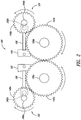
- FIG. 2 is a partially schematic front view of the internal combustion engine 100 illustrating the relationship of various components that control engine timing in accordance with an embodiment of the present technology.
- a number of components and/or systems e.g., sleeve valves, intake and exhaust tracks, etc.
- each of the connecting rods 106, 108 is pivotaliy coupled to a rod journal 242 (Identified individually as a first rod journal 242a and a second rod journal 242b) on the corresponding crankshaft 122, 124, respectively.
- the rod journals 242 are offset from main bearing journals 246 (Identified as a first main bearing journal 246a and a second main bearing journal 246b) which are aligned with the central axes of the crankshaft.
- crankshafts 122 and 124 are phased so that the pistons 102 and 104 arrive at their top dead center (TDC) positions at the same time.
- each of the crankshaft gears 140 is suitably meshed with the corresponding camshaft gear 142 to provide appropriate sleeve valve timing during engine operation.
- the phasing of one or both of the crankshafts 122 and 124, and/or one or both of the camshafts 150 can be changed to alter a number of different operating parameters of the engine 100.
- the crankshaft phasing and/or the valve phasing can be suitably changed to alter the compression ratio of the engine 100 as a function of load and/or other operating conditions.
- Figure 3 is a partially schematic, cross-sectional front view of an engine 300 having opposing crankshafts that are in phase (i.e., the phase angle between the two periodic cycles of the two crankshafts is zero degrees, or at least very near zero degrees).
- the engine 300 is an opposed-piston engine having a left or first piston 302 operably coupled to a first rod journal 342a on a first crankshaft 322, and a second piston 304 operably coupled to a second rod journal 342b on a right or second crankshaft 324.
- the pistons 302, 304 are at their TDC positions or "upper-most” positions on the exhaust stroke, and an exhaust sleeve valve 314 is nearing the closed position to seal off a corresponding exhaust port 332.
- an intake sleeve valve 316 has been closed and sealing off an intake passage or port 330 that is in fluid communication with the combustion chamber for a substantial portion of the exhaust stroke.
- the crankshafts 322, 324 are essentially "in phase,” meaning that the pistons 302 and 304 both arrive at their respective TDC positions at the same time, or at least at approximately the same time.
- the compression ratio can be varied by changing the phases of the crankshafts 322, 324 relative to each other.
- the phase of the master crankshaft i.e., the crankshaft that imparts the higher torque loads to the engine output shaft
- the slave crankshaft i.e., the crankshaft that transfers less torque to the output shaft
- Reducing the torque transfer in this manner can minimize or at least reduce the power transmission losses as well as torque peaks that may need to be dampened to prevent resonance in the crankshaft connections.
- Figures 4A-4F are a series of partially schematic, cross-sectional front views of an engine 400 for the purpose of illustrating some of the phasing technology discussed above.
- the engine 400 includes opposed pistons 402 and 404 operably coupled to corresponding crankshafts 422 and 424, respectively, by corresponding rod journals 442a and 442b, respectively.
- the first piston 402 reciprocates back and forth in a bore of an exhaust sleeve valve 414 which in turn moves back and forth to open and close an exhaust passage or port 432 during engine operation.
- the second piston 404 reciprocates back and forth in a bore of an intake sleeve valve 416 which opens and closes a corresponding intake port 430 during engine operation.
- the engine 400 includes a first phaser (not shown) associated with the first crankshaft 422 and a second phaser (also not shown) associated with the second crankshaft 424 to adjust the phasing (e.g., by retarding and advancing, respectively) of the respective crankshafts.
- the second crankshaft 424 can be defined as the master crankshaft and is advanced from its TDC position by an angle A.
- the second crankshaft 422 can be defined as the slave crankshaft 422 and is retarded from its TDC position by an amount equal to, or at least approximately equal to, the angle A.
- the master crankshaft 424 leads the slave crankshaft 422 by a total phase angle of 2xA (e.g., if A is 30 degrees, then the master crankshaft 424 leads the slave crankshaft 422 by 60 degrees).
- the slave crankshaft 422 is associated with the exhaust valve 414, while the master crankshaft 424 is associated with the intake sleeve valve 416.
- the slave crankshaft 422 can be associated with the intake valve 416 and the master crankshaft 424 can be associated with the exhaust valve 414.
- the valves 414 and 416 (or, more specifically, the associated camshaft or camshafts) can be phased independently and/or differently than the crankshafts 422 and 424.
- Figure 4A illustrates the first piston 402 as it closely approaches its TDC position on the exhaust stroke, while the second position 404 has just begun moving away from its TDC position.
- the intake/master side piston 404 is starting “down" its bore before the intake valve 416 has begun to open, resulting in less potential interference between the crown of the piston 404 and the leading edge of the intake valve 416 proximate the intake port 430.
- the friction of the piston 404 moving from left to right compliments the opening motion of the intake valve 416.
- the exhaust/slave side piston 402 lags the exhaust valve 414, so that the piston 402 is still part way down the bore and moving toward the TDC position as the exhaust valve 414 continues closing. This keeps the crown of the piston 402 away from the leading edge of the exhaust valve 414 as it closes, reducing the likelihood for interference while the frictional force of the moving piston 402 facilitates the right to left closing motion of the exhaust valve 414.
- the engine 400 includes a first phaser associated with the first crankshaft 422 and a second phaser associated with the second crankshaft 424 to individually adjust the phasing of the two crankshafts.
- first phaser associated with the first crankshaft 422
- second phaser associated with the second crankshaft 424 to individually adjust the phasing of the two crankshafts.
- valve timing would also have to be adjusted to maintain constant valve timing.
- the minimum combustion chamber volume e.g., the "effective TDC" for the engine cycle
- the intake valve were expected to start opening at the effective TDC, then the timing of the intake valve would have to be changed relative to both crankshafts. More specifically, the timing of the intake valve (and, for that matter, the exhaust valve) would have to be advanced by 10 degrees to maintain the same valve timing that occurred prior to advancing the master crankshaft by 20 degrees.
- the phaser associated with the master crankshaft can advance the master crankshaft 10 degrees ahead of the intake cam, and the phaser associated with the slave crankshaft can phase the slave crankshaft to lag the exhaust cam by 10 degrees.
- the timing of the intake cam and the exhaust cam would stay at a fixed relationship relative to each other and to the minimum chamber volume.
- a first phaser associated with the left crankshaft 122 could retard the left crankshaft 122, while a second phaser associated with the right crankshaft 124 could advance the right crankshaft by an equivalent amount. Doing so would not alter the timing of the camshafts 150 driven by the respective cam gears 142. Accordingly, the use of two phasers can simplify a variable compression ratio system for an opposed-piston internal combustion engine.
- the multiple phaser system described above is described in the context of a gear connection between the respective crankshafts and camshafts, the system works equally well with chain, belt drive, and/or other suitable connections between the respective crankshafts and camshafts.
- the first piston 402 reaches its physical top position (i.e., its TDC position) where it momentarily stops, while the second piston 404 is moving down the cylinder at a substantial pace.
- the intake sleeve valve 416 approaches the fully open position to draw air or an air/fuel mixture into the combustion chamber.
- leading the intake valve in this manner enables the piston 404 to impart a frictional load on the intake valve 416 that facilitates valve opening, while precluding interference between the piston crown and the intake port 430.
- the first piston 402 and the second piston 404 are closest to each other when the slave crankshaft 422 is at the angle A before TDC and the master crankshaft 424 is at the angle A after TDC.
- This position also corresponds to the maximum compression of the intake charge.
- the total volume of the combustion chamber increases by phasing the crankshafts and, as a result, phased crankshafts result in lower compression ratios.
- the piston position shown in Figure 4E corresponds to maximum compression of the intake charge, igniting the charge at or near this time could lead to inefficiencies because the first piston 402 would be driving against the contrary motion of the slave crankshaft 422. Accordingly, in one aspect of the present technology, intake charge ignition can be forestalled until the phased crankshafts 422 and 424 are in the subsequent positions shown in Figure 4F .
- one or more spark plugs 420 or other ignition sources can be used to ignite the intake charge when the slave crankshaft 422 is at the TDC position with the first piston 402 momentarily stopped, and the second piston 404 is partially down the cylinder and moving towards its BDC position.
- the combustion force applies a greater torque to the master crankshaft 424 because of the offset angle and leverage between the connecting rod 408 and corresponding rod journal 442b.
- This crankshaft phasing arrangement reduces the torque transferred from the slave crankshaft 422 to the master crankshaft 424 and also helps reduce power transmission losses as well as torque peaks that may cause resonance in the driveline.
- crankshaft phasing to vary compression ratio in opposed-piston engines without having to alter valve timing.
- valve timing can also be adjusted with compression ratio to provide desirable characteristics by implementing one or more phasers to control operation of one or more camshafts.
- Figures 4A-4F and the related discussion above describe operation of a four stroke, opposed- piston engine (i.e., an engine in which the pistons perform four strokes per engine cycle: intake, compression, power, and exhaust), other embodiments of the methods and systems disclosed herein can be implemented with two stroke engines (i.e., an engine in which the pistons perform two strokes per engine cycle: intake/compression and combustion/exhaust).
- Figures 5A-5D include a series of graphs 500a-d, respectively, illustrating piston positions and effective cylinder displacements as a function of crankshaft angle for various embodiments of the phased crankshaft, opposed-piston engines described in detail above.
- the first graph 500a measures cylinder displacement in cubic centimeters (cc) along a vertical axis 502, and crankshaft angle in degrees along a horizontal axis 504.
- a first plot line 510 describes the path or periodic cycle of a first piston, such as the piston 402 shown in Figures 4A-4F
- a second plot line 508 describes the path or periodic cycle of an opposing second piston, such as the piston 404.
- a third plot line 506 illustrates the change in the total chamber volume as a function of crankshaft angle.
- the two crankshafts are in phase (i.e., there is zero degrees phasing or phase angle between the crankshafts), resulting in, e.g., a 250cc cylinder displacement for a maximum effective compression ratio of 15:1 with a minimum combustion chamber volume occurring at 180 degrees (i.e., when both crankshafts are at TDC).
- the periodic cycles of the two pistons remains the same, but the timing of the first piston and the second piston (i.e., the relative positions of the two pistons at any given time) changes. More specifically, in this embodiment the second piston as shown by the second plot line 508 leads the first piston as shown by the first plot line 510 by a phase angle of 30 degrees. Although the displacement of each individual piston does not change, the total cylinder displacement is reduced to 241 ccs as shown by the third plot line 506.
- the distance between the peaks and valleys of the third plot line 506 represent 241 ccs, in contrast to the 250ccs represented by the peak-to-valley distance of the third plot line 506 in the first graph 500a.
- phasing the crankshafts (and, accordingly, the corresponding pistons) as shown in the second graph 500b by 30 degrees results in a 12.5:1 effective compression ratio because of the reduced cylinder displacement and increased "closest" distance between pistons.
- the minimum combustion chamber volume no longer occurs at 180 degrees, but instead occurs at 165 (i.e., 15 degrees before TDC of, e.g., the first piston).
- the minimum combustion chamber volume "lags" the master crankshaft (e.g., the crankshaft coupled to the second piston shown by line 508) by one half the angle (e.g., one half of 30 degrees, or 15 degrees) that the slave crankshaft lags the master crankshaft.
- variable compression ratio can be altered by changing the initial set up conditions of the engine. For example, in another engine configuration the same phase change of 60 degrees could result in a reduction in compression ratio of from 20:1 to 9.3:1 , with the minimum combustion chamber volume occurring at the same location for each configuration. Accordingly, the compression ratio range can be altered by changing the initial operating conditions (e.g., the initial compression ratio) of a particular engine.
- Figure 6A is a graph 600 illustrating total cylinder volume as a function of crankshaft phase angle for an opposed-piston engine
- Figure 6B is an enlarged view of a portion of the graph 600.
- the total cylinder displacement decreases as the phase angle between crankshafts increases. This is illustrated by a first plot line 606a, which shows that the total displacement with 0 degrees lag of the slave crankshaft has the highest displacement (e.g., 250ccs) and the correspondingly highest compression ratio 15:1.
- an active phase change system as described herein can be used to efficiently reduce (or increase) the compression ratio of an opposed- piston engine to best fit the particular operating conditions (e.g., light loads, high loads, fuel, etc.) of an engine.
- phasing devices that can be used to actively vary the phase angle of crankshafts (and/or camshafts) in the manner described above.
- FIG. 7A is a partially schematic, cross sectional side view of a phase change assembly or "phaser" 700a configured in accordance with an embodiment of the present technology.
- the phaser 700a can be operably coupled to a master crankshaft and a slave crankshaft (one per crankshaft) to provide the dual crankshaft phasing features described in detail above.
- the phaser 700a can also be coupled to a single crankshaft for single phasing, and/or to one or more camshafts.
- the phaser 700a includes a phasing head 762a that is operably coupled to a distal end of a crankshaft (e.g., the first or slave crankshaft 322 described above with reference to Figure 3 ). More specifically, in the illustrated embodiment an end portion of the crankshaft 322 includes a plurality of (e.g.) left hand helical splines or gear teeth 724 on an outer surface thereof which engage complimentary or matching left hand helical gear teeth 780 on an internal surface of a central portion of the phasing head 762a.
- a crankshaft e.g., the first or slave crankshaft 322 described above with reference to Figure 3 .
- an end portion of the crankshaft 322 includes a plurality of (e.g.) left hand helical splines or gear teeth 724 on an outer surface thereof which engage complimentary or matching left hand helical gear teeth 780 on an internal surface of a central portion of the phasing head 762a.
- right hand helical gear teeth 782 can be provided on an adjacent outer surface of the phasing head 762a to engage matching right hand helical gear teeth 784 on a crankshaft drive member, such as a crankshaft gear 740a.
- the phasing head 762a is free to move fore and aft relative to a cylindrical valve body 765 in a hydraulic fluid (e.g., oil) cavity having a front side volume 774 and a back side volume 778.
- the phasing head 762a includes a first oil passage 770 leading from an outer surface to the front side volume 774, and a second oil passage 772 leading from the outer surface to the back side volume 778.
- the valve body 765 can flow oil from an oil supply 766 into the phasing head cavity via a supply passage 767.
- the valve body 765 also includes a first outflow passage 776a and a second outflow passage 776d.
- an actuator 764 is moved in a desired direction (e.g., in a forward direction F) to move the valve body 765 in the same direction.
- a desired direction e.g., in a forward direction F
- the oil supply passage 767 aligns with the first oil passage 770.
- Oil from the oil supply 766 then flows through the first oil passage 770 and into the front side volume 774, driving the phasing head 762a in the direction F.
- oil in the back side volume 778 escapes via the second oil passage 772, which instead of being blocked by the valve body 765 is now in fluid communication with the first outflow passage 776a.
- the phasing head 762a and the crankshaft gear 740a do rotate with the crankshaft 322.
- the relative motion between the left hand helical gear teeth 780 on the internal bore of the phasing head 762a and the engaging teeth 734 on the crankshaft 322 causes the crankshaft 322 to rotate relative to the phasing head 762a.
- crankshaft gear 740a rotates in the opposite direction relative to the phasing head 762a and, accordingly, the crankshaft 322.
- movement of the phasing head 762a causes the operational angle between the crankshaft gear 740a and the crankshaft 322 to change in proportion to the movement of the phasing head 762a.
- the actuator 764 can be moved in the direction opposite to the direction F to slide the valve body 765 from left to right relative to the phasing head 762a. Doing so aligns the oil supply passage 767 with the second oil passage 772 in the phasing head 762, which directs pressurized oil into the back side volume 778. The pressurized oil flowing into this volume drives the phasing head 762 from left to right in the direction opposite to the direction F, thereby reducing the phase angle between the crankshaft gear 740a and the crankshaft 322.
- crankshaft gear 740a (which could also be a pulley, sprocket, etc.) is held in a horizontally fixed position relative to the crankcase 768 and, accordingly, is held in a horizontally fixed relationship relative to the gear (or belt, chain, etc.; not shown) it engages to drive a corresponding camshaft (and/or other device such as an ignition device, oil/water pump, etc).
- Figure 7B illustrates a phaser 700b that has many features and components which are generally similar in structure and function to the phaser 700a described above.
- a phasing head 762b can be moved from left to right and vice versa as described above with reference to Figure 7A .
- the phasing head 762b can include, e.g., left hand helical gear teeth 780 which engaged complimentary helical gear teeth 724 on the crankshaft 322.
- a crankshaft drive member such as a toothed pulley 740b is fixedly attached to a distal end of a phasing head 762b by one or more fasteners (e.g. bolts) 786. Accordingly, the pulley 740b moves with the phasing head 762b as the phasing head 762b moves back and forth horizontally relative to the crankcase 768. Moreover, in this embodiment the pulley 740b is operably coupled to, e.g., a corresponding camshaft (not shown) by means of a toothed belt 788.
- belt guides 790a and 790b are positioned on opposite sides of the belt 788 to restrict lateral movement of the belt as the pulley 740b moves horizontally.
- movement of the phasing head 762b in the direction F can functionally increase (or decrease) the phase angle between the crankshaft 322 and the corresponding valve/camshaft arrangement, while movement of the phasing head 762b in the opposite direction can reduce (or increase) the phase angle between the crankshaft 322 and the camshaft/valve.
- FIG. 7C illustrates yet another embodiment of a phaser 700c configured in accordance with the present technology.
- Many features and of the phaser 700c are at least generally similar in structure and function to the corresponding features of the phaser 700b described in detail above with reference to Figure 7B .
- a crankshaft gear 740c is fixedly attached to a distal end of the phasing head 762b.
- the crankshaft gear 740c operably engages a power transfer gear 742 (e.g., a gear that couples the crankshaft 322 to a corresponding camshaft).
- the gear 742 can include either straight or helical gear teeth which engage corresponding gear teeth 792 on the outer perimeter of the crankshaft gear 740c.
- crankshaft gear 740c and the power transfer gear 742 can include helical gear teeth as well as straight-cut gear teeth. If the gear teeth 792 are helical gear teeth that angle in a direction opposite to the helical gear teeth 724, then movement of the crankshaft gear 740c can result in additional phase change angle because of the opposite directions of the two sets of gear teeth.
- FIG. 8 is a schematic diagram of a phaser assembly 800 that can be utilized with various embodiments of the present technology.
- the phaser assembly 800 can be at least generally similar in structure and function to a commercially available variable cam phaser provided by Delphi Automotive LLP.
- the phaser assembly 800 includes a camshaft 822 coupled to a phasing head 890 having a first lobe 892a, a second lobe 892b, a third lobe 892c, and a fourth lobe 892d.
- a control valve 865 controls the flow of oil either into or out of the cavities on opposite sides of the lobes 892 via supply passages 870a and 870b.
- Increasing the oil pressure on, e.g., the left side of each lobe 892 causes the phasing head 890 to rotate clockwise as viewed in Figure 8 .
- increasing the oil pressure on the right side of each lobe 892 causes the phasing head 890 to rotate counterclockwise as the oil flows out of the opposing cavity via the return line 870b.
Landscapes
- Engineering & Computer Science (AREA)
- Mechanical Engineering (AREA)
- General Engineering & Computer Science (AREA)
- Chemical & Material Sciences (AREA)
- Combustion & Propulsion (AREA)
- Output Control And Ontrol Of Special Type Engine (AREA)
- Valve Device For Special Equipments (AREA)
Applications Claiming Priority (4)
| Application Number | Priority Date | Filing Date | Title |
|---|---|---|---|
| US39153010P | 2010-10-08 | 2010-10-08 | |
| US201161501677P | 2011-06-27 | 2011-06-27 | |
| US201161511521P | 2011-07-25 | 2011-07-25 | |
| EP11831731.2A EP2625404B1 (de) | 2010-10-08 | 2011-10-07 | System mit variablem verdichtungsverhältnis für gegenkolben- und andere verbrennungsmotoren sowie verfahren zu seiner herstellung und verwendung |
Related Parent Applications (1)
| Application Number | Title | Priority Date | Filing Date |
|---|---|---|---|
| EP11831731.2A Division EP2625404B1 (de) | 2010-10-08 | 2011-10-07 | System mit variablem verdichtungsverhältnis für gegenkolben- und andere verbrennungsmotoren sowie verfahren zu seiner herstellung und verwendung |
Publications (2)
| Publication Number | Publication Date |
|---|---|
| EP3190259A2 true EP3190259A2 (de) | 2017-07-12 |
| EP3190259A3 EP3190259A3 (de) | 2017-09-20 |
Family
ID=45924126
Family Applications (2)
| Application Number | Title | Priority Date | Filing Date |
|---|---|---|---|
| EP16002748.8A Withdrawn EP3190259A3 (de) | 2010-10-08 | 2011-10-07 | System mit variablem verdichtungsverhältnis für gegenkolben-verbrennungsmotoren sowie verfahren zur herstellung und verwendung |
| EP11831731.2A Not-in-force EP2625404B1 (de) | 2010-10-08 | 2011-10-07 | System mit variablem verdichtungsverhältnis für gegenkolben- und andere verbrennungsmotoren sowie verfahren zu seiner herstellung und verwendung |
Family Applications After (1)
| Application Number | Title | Priority Date | Filing Date |
|---|---|---|---|
| EP11831731.2A Not-in-force EP2625404B1 (de) | 2010-10-08 | 2011-10-07 | System mit variablem verdichtungsverhältnis für gegenkolben- und andere verbrennungsmotoren sowie verfahren zu seiner herstellung und verwendung |
Country Status (5)
| Country | Link |
|---|---|
| US (2) | US8413619B2 (de) |
| EP (2) | EP3190259A3 (de) |
| CN (2) | CN202417706U (de) |
| BR (1) | BR112013009242A2 (de) |
| WO (1) | WO2012048301A1 (de) |
Families Citing this family (60)
| Publication number | Priority date | Publication date | Assignee | Title |
|---|---|---|---|---|
| US7559298B2 (en) | 2006-04-18 | 2009-07-14 | Cleeves Engines Inc. | Internal combustion engine |
| WO2012048301A1 (en) | 2010-10-08 | 2012-04-12 | Pinnacle Engines, Inc. | Variable compression ratio systems for opposed-piston and other internal combustion engines, and related methods of manufacture and use |
| US8881708B2 (en) | 2010-10-08 | 2014-11-11 | Pinnacle Engines, Inc. | Control of combustion mixtures and variability thereof with engine load |
| US9650951B2 (en) | 2010-10-08 | 2017-05-16 | Pinnacle Engines, Inc. | Single piston sleeve valve with optional variable compression ratio capability |
| CH703972A1 (de) * | 2010-10-29 | 2012-04-30 | Obrist Engineering Gmbh | Verbrennungskraftmaschine. |
| US8439010B2 (en) * | 2010-11-03 | 2013-05-14 | Edwin M. Fernandez | Internal combustion engine |
| US9513045B2 (en) | 2012-05-03 | 2016-12-06 | Whirlpool Corporation | Heater-less ice maker assembly with a twistable tray |
| US8443769B1 (en) | 2012-05-18 | 2013-05-21 | Raymond F. Lippitt | Internal combustion engines |
| AU2013263355B2 (en) | 2012-05-18 | 2017-02-02 | Raymond F. Lippitt | Internal combustion engines |
| BR112015000026A2 (pt) | 2012-07-02 | 2017-06-27 | Pinnacle Engines Inc | motor a diesel de relação de compressão variável |
| WO2014040205A1 (zh) * | 2012-09-11 | 2014-03-20 | Liang Guoqiang | 一种卧式柴油发动机 |
| US9303559B2 (en) | 2012-10-16 | 2016-04-05 | Raymond F. Lippitt | Internal combustion engines |
| US8925335B2 (en) | 2012-11-16 | 2015-01-06 | Whirlpool Corporation | Ice cube release and rapid freeze using fluid exchange apparatus and methods |
| US9599385B2 (en) | 2012-12-13 | 2017-03-21 | Whirlpool Corporation | Weirless ice tray |
| US9410723B2 (en) | 2012-12-13 | 2016-08-09 | Whirlpool Corporation | Ice maker with rocking cold plate |
| US9557087B2 (en) | 2012-12-13 | 2017-01-31 | Whirlpool Corporation | Clear ice making apparatus having an oscillation frequency and angle |
| US9303903B2 (en) | 2012-12-13 | 2016-04-05 | Whirlpool Corporation | Cooling system for ice maker |
| US9500398B2 (en) | 2012-12-13 | 2016-11-22 | Whirlpool Corporation | Twist harvest ice geometry |
| US9470448B2 (en) | 2012-12-13 | 2016-10-18 | Whirlpool Corporation | Apparatus to warm plastic side of mold |
| US9518773B2 (en) | 2012-12-13 | 2016-12-13 | Whirlpool Corporation | Clear ice maker |
| US9476629B2 (en) | 2012-12-13 | 2016-10-25 | Whirlpool Corporation | Clear ice maker and method for forming clear ice |
| US9759472B2 (en) | 2012-12-13 | 2017-09-12 | Whirlpool Corporation | Clear ice maker with warm air flow |
| US9310115B2 (en) | 2012-12-13 | 2016-04-12 | Whirlpool Corporation | Layering of low thermal conductive material on metal tray |
| US9518770B2 (en) | 2012-12-13 | 2016-12-13 | Whirlpool Corporation | Multi-sheet spherical ice making |
| US9599388B2 (en) | 2012-12-13 | 2017-03-21 | Whirlpool Corporation | Clear ice maker with varied thermal conductivity |
| US10190492B2 (en) * | 2013-04-08 | 2019-01-29 | Achates Power, Inc. | Dual crankshaft, opposed-piston engines with variable crank phasing |
| JP6039503B2 (ja) * | 2013-05-21 | 2016-12-07 | 株式会社デンソー | 内燃機関 |
| WO2015013696A1 (en) | 2013-07-26 | 2015-01-29 | Pinnacle Engines, Inc. | Early exhaust valve opening for improved catalyst light off |
| WO2015069536A1 (en) | 2013-11-05 | 2015-05-14 | Lippitt Raymond F | Engine with central gear train |
| US9664044B2 (en) | 2013-11-15 | 2017-05-30 | Raymond F. Lippitt | Inverted V-8 I-C engine and method of operating same in a vehicle |
| US9217365B2 (en) | 2013-11-15 | 2015-12-22 | Raymond F. Lippitt | Inverted V-8 internal combustion engine and method of operating the same modes |
| WO2015123262A1 (en) | 2014-02-12 | 2015-08-20 | Achates Power, Inc. | A low reactivity, compression-ignition, opposed-piston engine |
| EP3155222B1 (de) * | 2014-06-16 | 2018-09-19 | Volvo Truck Corporation | Zweitaktgegenkolbenbrennkraftmaschine |
| WO2016065269A2 (en) | 2014-10-23 | 2016-04-28 | Whirlpool Corporation | Method and apparatus for increasing rate of ice production in an automatic ice maker |
| US10036344B2 (en) | 2015-02-27 | 2018-07-31 | Avl Powertrain Engineering, Inc. | Opposed piston two stroke engine liner construction |
| US10072604B2 (en) | 2015-02-27 | 2018-09-11 | Avl Powertrain Engineering, Inc. | Engine block construction for opposed piston engine |
| EP3420206A4 (de) * | 2016-02-22 | 2019-08-14 | Two Heads Llc | Kompakter gegenkolbenmotor mit auf einer anderen anlage als jene der zylinderachsen rotierenden kurbelwellen |
| US11085297B1 (en) * | 2016-02-24 | 2021-08-10 | Enginuity Power Systems, Inc | Opposed piston engine and elements thereof |
| US10161307B2 (en) * | 2016-05-17 | 2018-12-25 | Fairbanks Morse Llc | Bilateral engine control system |
| CN105937440A (zh) * | 2016-05-21 | 2016-09-14 | 中北大学 | 一种对置活塞二冲程可变压缩比汽油机 |
| CN105862202B (zh) * | 2016-05-27 | 2018-12-28 | 苏州市丹纺纺织研发有限公司 | 一种降噪空气丝喷嘴结构 |
| DE112017004757A5 (de) * | 2016-09-22 | 2019-06-19 | Schaeffler Technologies AG & Co. KG | Stelleinheit einer brennkraftmaschine |
| CN110291273B (zh) * | 2017-03-20 | 2021-08-31 | 沃尔沃卡车集团 | 具有偏移的进气曲轴和排气曲轴的对置活塞式发动机 |
| US10739053B2 (en) | 2017-11-13 | 2020-08-11 | Whirlpool Corporation | Ice-making appliance |
| US10962350B2 (en) * | 2017-12-14 | 2021-03-30 | Cummins Inc. | Systems and methods for measurement of piston-to-piston clearances in multi-cylinder opposed piston engines |
| JP7037804B2 (ja) | 2018-01-15 | 2022-03-17 | 国立大学法人広島大学 | 発電装置および自動車 |
| JP2019183730A (ja) * | 2018-04-09 | 2019-10-24 | トヨタ自動車株式会社 | 対向ピストン内燃機関 |
| US10907874B2 (en) | 2018-10-22 | 2021-02-02 | Whirlpool Corporation | Ice maker downspout |
| US11598259B2 (en) | 2019-08-29 | 2023-03-07 | Achates Power, Inc. | Hybrid drive system with an opposed-piston, internal combustion engine |
| US11454165B2 (en) * | 2020-02-02 | 2022-09-27 | Creed Engines, Llc | Optimal efficiency internal combustion engine |
| CN113389611A (zh) * | 2020-03-12 | 2021-09-14 | 赵天安 | 一种进气调节机构、一种发动机和一种气动马达 |
| US11136916B1 (en) * | 2020-10-06 | 2021-10-05 | Canadavfd Corp (Ltd) | Direct torque control, piston engine |
| EP4001608B1 (de) * | 2020-11-17 | 2024-10-16 | Volvo Truck Corporation | Verbrennungsmotorsystem |
| US12570526B2 (en) | 2021-05-18 | 2026-03-10 | M2X Energy Inc. | Systems, devices and methods for input and output pressure management of air breathing engine reformers |
| EP4469398A4 (de) * | 2022-01-28 | 2026-01-28 | M2X Energy Inc | Verfahren, systeme und vorrichtung zur kohlenstofferfassung, -verwendung und -lagerung |
| LV15764A (lv) * | 2022-02-02 | 2023-08-20 | Apex Dynamics, Sia | Pretstatītu virzuļu iekšdedzes dzinējs |
| US20250239912A1 (en) * | 2024-01-19 | 2025-07-24 | Enginuity Power Systems, Inc. | Methods and devices for integrating generators in an engine |
| US20250354528A1 (en) * | 2024-05-20 | 2025-11-20 | GM Global Technology Operations LLC | Valve system for two-stroke engine |
| US12421891B1 (en) | 2024-08-30 | 2025-09-23 | Saudi Arabian Oil Company | High-speed long-stroke reciprocating engine |
| JP7790798B1 (ja) * | 2025-09-12 | 2025-12-23 | 株式会社エッチ・ケー・エス | 対向ピストン2ストロークエンジン |
Family Cites Families (118)
| Publication number | Priority date | Publication date | Assignee | Title |
|---|---|---|---|---|
| US367496A (en) | 1887-08-02 | atkinson | ||
| US1082004A (en) | 1913-12-23 | Gen Electric | Governing internal-combustion engines. | |
| US1472549A (en) | 1923-10-30 | Internal-combustion engine | ||
| US1459819A (en) | 1923-06-26 | Clarence e | ||
| US1316977A (en) | 1919-09-23 | Cardo | ||
| US1097947A (en) | 1914-05-26 | Allan D Shaw | Internal-combustion engine. | |
| FR348575A (fr) | 1903-12-05 | 1905-04-17 | Francis Lyst | Machine à combustion interne et moteur à pétrole |
| GB190902015A (en) | 1909-01-27 | 1909-08-05 | Eugene Guy Euston Beaumont | Improved Method of and Means for Automatically Varying the Volume of the Compression Chamber in Internal Combustion Engines. |
| US1140987A (en) | 1913-09-19 | 1915-05-25 | Frederick E Kube | Engine-cooling system. |
| US1258524A (en) | 1915-11-02 | 1918-03-05 | John Franklin Berry | Internal-combustion engine. |
| FR497282A (fr) | 1918-04-04 | 1919-12-02 | Georges Rene Eugene Briens | Moteur à explosions sans soupapes |
| US1453304A (en) | 1919-08-15 | 1923-05-01 | James A Charter | Explosive engine |
| US1497206A (en) | 1919-12-23 | 1924-06-10 | John G Booton | Regulating valve control for internal-combustion engines |
| US1502291A (en) | 1920-09-07 | 1924-07-22 | George E Conway | Valve for motors |
| US1377798A (en) | 1920-12-22 | 1921-05-10 | Berckenhoff Hemke | Cylindrical or sleeve valve |
| US1550643A (en) | 1923-07-12 | 1925-08-18 | Bullington Motors | Reciprocatory internal-combustion engine |
| US1644954A (en) | 1924-11-12 | 1927-10-11 | Shearer James | Reciprocating engine |
| US1634768A (en) | 1925-05-15 | 1927-07-05 | Bonner Charter Corp | Engine lubrication |
| US1673340A (en) | 1925-06-16 | 1928-06-12 | Panhard & Levassor | Sleeve-valve engine |
| US1773971A (en) | 1927-08-25 | 1930-08-26 | William C Dunn | Slide-valve motor |
| US1856242A (en) | 1927-09-30 | 1932-05-03 | Aix Fritz C L D | Internal combustion engine |
| US1823770A (en) | 1928-11-26 | 1931-09-15 | Tartrais Eugene Henri | Engine of the two-stroke type |
| US1837870A (en) | 1928-12-03 | 1931-12-22 | Johnston Tractors Company Ltd | Double piston single cylinder internal combustion engine |
| US1812323A (en) | 1929-06-10 | 1931-06-30 | Davison Engineering Corp | Internal combustion engine |
| US1819897A (en) | 1929-10-26 | 1931-08-18 | Johnson Hamilton | Internal combustion engine |
| US1889946A (en) | 1930-01-15 | 1932-12-06 | Headless Multiple Motor Corp | Gas engine |
| GB382670A (en) | 1930-08-09 | 1932-10-31 | Adolphe Kegresse | Improvements in or relating to the feeding of two- or more-cylinder internal combustion engines |
| US2121409A (en) | 1934-10-19 | 1938-06-21 | Ricardo Harry Ralph | Two-stroke internal-combustion engine |
| DE643470C (de) | 1935-02-06 | 1937-04-08 | Ernst Schmid | Brennkraftmaschine |
| FR805866A (fr) | 1935-04-06 | 1936-12-02 | United Aircraft Corp | Perfectionnements relatifs aux moteurs du type à fourreau de distribution |
| US2090889A (en) | 1935-05-16 | 1937-08-24 | Howald Werner | Internal combustion engine |
| US2199625A (en) | 1937-06-11 | 1940-05-07 | Fiala-Fernbrugg Benno | Double-piston internal combustion engine |
| GB534161A (en) | 1939-01-03 | 1941-02-28 | Milo Ab | Improvements in or relating to internal combustion engines of the four-stroke cycle type |
| GB542009A (en) | 1940-06-18 | 1941-12-22 | Arthur John Rowledge | Improvements in or relating to liquid-cooling systems for sleevevalve internal-combustion engines |
| US2273179A (en) | 1940-08-30 | 1942-02-17 | Davison Douglas Corp | Rotary valve and lubrication thereof |
| US2401188A (en) * | 1943-03-01 | 1946-05-28 | Gen Electric | Internal-combustion engine with variable compression ratio |
| US2409761A (en) | 1945-02-24 | 1946-10-22 | Gen Motors Corp | Sleeve valve engine |
| GB635664A (en) | 1948-01-23 | 1950-04-12 | George Urban Leonard Sartoris | Improvements in high-speed air and gas compressors |
| US2686507A (en) | 1952-03-06 | 1954-08-17 | Lombardi Leo | Sleeve valve system |
| US2773490A (en) | 1952-09-23 | 1956-12-11 | Miller Ralph | High expansion, spark ignited, gas burning, internal combustion engines |
| GB746820A (en) | 1953-11-06 | 1956-03-21 | English Electric Co Ltd | Improvements in and relating to two-stroke cycle internal combustion engines |
| US2937631A (en) | 1956-04-18 | 1960-05-24 | Charles A Coyle | High efficiency internal combustion engine |
| US2817322A (en) | 1956-04-30 | 1957-12-24 | Miller Ralph | Supercharged engine |
| US2858816A (en) * | 1957-10-08 | 1958-11-04 | Leon A Prentice | Internal combustion engines of the variable compression type |
| US3533429A (en) | 1967-11-22 | 1970-10-13 | Stanford Research Inst | Pneumatically operated valve |
| US3485221A (en) | 1967-12-11 | 1969-12-23 | Ralph S Feeback | Omnitorque opposed piston engine |
| US3780719A (en) | 1971-07-30 | 1973-12-25 | A Weiertz | Internal combustion engine |
| US3961607A (en) * | 1972-05-12 | 1976-06-08 | John Henry Brems | Internal combustion engine |
| JPS5930899B2 (ja) | 1973-02-01 | 1984-07-30 | 隆弘 上野 | 内燃機関の制動方法及びその装置 |
| US3948241A (en) | 1973-08-02 | 1976-04-06 | Melchior Frederick C | Lubricating and sealing system for internal combustion engines |
| IT1055604B (it) | 1975-08-27 | 1982-01-11 | Grandi Motori Trieste Spa | Camicia di cilindru con condotti interni di raffreddamento per motori alternativi a combustione interna |
| GB1516982A (en) | 1975-09-15 | 1978-07-05 | Jones R | Reciprocating piston heat engines |
| US4057040A (en) | 1976-04-12 | 1977-11-08 | Wax Archie E | Internal combustion engine system |
| US4104995A (en) | 1976-12-15 | 1978-08-08 | Rolf Steinbock | Variable compression engine |
| FR2401898A1 (fr) | 1977-09-05 | 1979-03-30 | Aec Chim Organ Biolog | Nouveau sel de l'acide patoique |
| US4187807A (en) | 1978-02-22 | 1980-02-12 | Caterpillar Tractor Co. | Cooled engine valve with improved heat transfer |
| JPS56106040A (en) | 1980-01-29 | 1981-08-24 | Nippon Denso Co Ltd | Engine controlling method |
| JPS57185689A (en) | 1981-05-09 | 1982-11-15 | Nippon Soken | Multipoint ignition plug |
| US4516537A (en) | 1982-03-24 | 1985-05-14 | Daihatsu Motor Company | Variable compression system for internal combustion engines |
| US4928658A (en) | 1985-10-02 | 1990-05-29 | Ferrenberg Allan J | Regenerative internal combustion engine |
| US5058536A (en) | 1987-01-28 | 1991-10-22 | Johnston Richard P | Variable-cycle reciprocating internal combustion engine |
| US4856463A (en) * | 1987-01-28 | 1989-08-15 | Johnston Richard P | Variable-cycle reciprocating internal combustion engine |
| JPH0517455Y2 (de) | 1987-03-31 | 1993-05-11 | ||
| US4815421A (en) | 1987-05-18 | 1989-03-28 | Paul Marius A | Internal combustion engine with adjustable flow exhaust system |
| US4838214A (en) | 1987-06-18 | 1989-06-13 | Barrett George M | Internal combustion engine assembly |
| JPH0658046B2 (ja) | 1988-06-10 | 1994-08-03 | 孝夫 高草 | 往復ピストン機関のスリーブ端バルブ |
| US4876992A (en) * | 1988-08-19 | 1989-10-31 | Standard Oil Company | Crankshaft phasing mechanism |
| US5113805A (en) | 1989-12-12 | 1992-05-19 | Isuzu Ceramics Research Institute Co., Ltd. | Variable-cycle engine |
| US5025757A (en) | 1990-09-13 | 1991-06-25 | Larsen Gregory J | Reciprocating piston engine with a varying compression ratio |
| US5054438A (en) | 1990-09-19 | 1991-10-08 | Jiro Takashima | Floating cylinder internal combustion engine |
| US5127375A (en) | 1991-04-04 | 1992-07-07 | Ford Motor Company | Hydraulic valve control system for internal combustion engines |
| US5159906A (en) | 1991-05-03 | 1992-11-03 | Ford Motor Company | Adjustable valve system for an internal combustion engine |
| US5255637A (en) | 1992-04-30 | 1993-10-26 | Ford Motor Company | Internal combustion engine with adaptive control of compression ratio |
| US5803042A (en) | 1992-07-27 | 1998-09-08 | Bortone; Cesare | Valves and valve timing for internal combustion engine |
| SK283980B6 (sk) | 1993-06-26 | 2004-06-08 | Coventry University | Spaľovací motor a spôsob regulácie procesu spaľovacieho motora |
| US5507253A (en) | 1993-08-27 | 1996-04-16 | Lowi, Jr.; Alvin | Adiabatic, two-stroke cycle engine having piston-phasing and compression ratio control system |
| US5445117A (en) | 1994-01-31 | 1995-08-29 | Mendler; Charles | Adjustable valve system for a multi-valve internal combustion engine |
| US5623894A (en) | 1995-11-14 | 1997-04-29 | Caterpillar Inc. | Dual compression and dual expansion engine |
| JPH09280370A (ja) | 1996-04-08 | 1997-10-28 | Nabco Ltd | シリンダ装置 |
| JPH1038083A (ja) | 1996-07-25 | 1998-02-13 | Akebono Brake Ind Co Ltd | 嵌合部用ブーツ |
| US6230683B1 (en) | 1997-08-22 | 2001-05-15 | Cummins Engine Company, Inc. | Premixed charge compression ignition engine with optimal combustion control |
| US6039011A (en) * | 1997-03-05 | 2000-03-21 | The American University Of Baku | Internal combustion engine with opposed pistons |
| JPH10311231A (ja) | 1997-05-12 | 1998-11-24 | Toyota Motor Corp | 内燃機関の出力制御装置 |
| US6125801A (en) | 1997-11-25 | 2000-10-03 | Mendler; Edward Charles | Lean-burn variable compression ratio engine |
| DE19813398C1 (de) | 1998-03-26 | 1999-09-09 | Blodig | Vorrichtung zur Verstellung des Verdichtungsverhältnisses und der Steuerzeiten bei Brennkraftmaschinen |
| JP2002529635A (ja) | 1998-10-30 | 2002-09-10 | ポーレット メルモス ウォルターズ,クリストファー | バルブ制御機構 |
| US6230671B1 (en) | 1998-11-02 | 2001-05-15 | Raymond C. Achterberg | Variable compression and asymmetrical stroke internal combustion engine |
| US6205963B1 (en) | 1999-04-06 | 2001-03-27 | Jim W Davies | High power density, low emission internal combustion engine |
| JP4149621B2 (ja) | 1999-09-03 | 2008-09-10 | 邦彦 奥平 | 対向ピストン式2サイクルユニフロー型機関 |
| WO2001040642A1 (en) | 1999-12-03 | 2001-06-07 | Nissan Motor Co., Ltd. | Intake-air quantity control apparatus for internal combustion engines |
| JP4053201B2 (ja) | 1999-12-21 | 2008-02-27 | 株式会社日立製作所 | 内燃機関の可変動弁装置 |
| DE10023442A1 (de) | 2000-05-12 | 2001-11-15 | Ullrich Meyer | Motor mit gegenläufigen Kolben |
| JP2004239182A (ja) | 2003-02-06 | 2004-08-26 | Toyota Motor Corp | エンジンのピストン駆動装置 |
| WO2004092621A1 (en) | 2003-04-09 | 2004-10-28 | Dimitrios Dardalis | Hydrodynamic seal and method for sealing a rotating sleeve engine |
| US20040244758A1 (en) | 2003-06-06 | 2004-12-09 | Cummins Inc. | Method for increasing the displacement of an internal combustion engine and engine having increased displacement thereby |
| JP4325492B2 (ja) * | 2003-06-17 | 2009-09-02 | トヨタ自動車株式会社 | 可変動弁の制御装置及び方法 |
| JP2005113839A (ja) | 2003-10-09 | 2005-04-28 | Toyota Motor Corp | 可変圧縮比内燃機関 |
| DE102004032452A1 (de) | 2004-07-05 | 2006-01-26 | Daude, Otto, Dr.-Ing. | Gaswechselsteuerung für Gegenkolbenmotoren |
| DE202006020546U1 (de) | 2005-07-08 | 2009-01-08 | Daude, Otto, Dr.-Ing. | Gegenkolbenmotoren mit Schiebebüchsen und Gaswechselsteuerung |
| GB2428450B (en) | 2005-07-15 | 2007-08-01 | Lotus Car | Opposed piston engine with variable timing |
| GB0521960D0 (en) | 2005-10-28 | 2005-12-07 | Leonard Gregory L | Improved internal combustion engine |
| GB2432398B (en) | 2005-11-18 | 2008-08-13 | Lotus Car | Reciprocating piston sleeve valve engine |
| GB2438206B (en) | 2006-01-23 | 2009-02-04 | Lotus Car | A two-stroke internal combustion engine with variable compression ratio and an exhaust port shutter |
| US7559298B2 (en) * | 2006-04-18 | 2009-07-14 | Cleeves Engines Inc. | Internal combustion engine |
| FR2900683A1 (fr) | 2006-05-05 | 2007-11-09 | Max Louis Maurice Hostache | Moteur a explosion a rendement eleve |
| FR2900974B1 (fr) | 2006-05-15 | 2008-08-08 | Renault Sas | Procede de detection d'une perte de combustion et application a la commande d'un moteur a taux de compression variable (vcr) |
| WO2008016289A1 (es) * | 2006-07-31 | 2008-02-07 | Pastor Alvarez Jose Enrique | Cámara de combustión interna de dos tiempos con dos pistones encontrados por cilindro |
| US20080127947A1 (en) | 2006-11-30 | 2008-06-05 | Advanced Propulsion Technologies, Inc. | OPOC engine |
| US7584724B2 (en) * | 2007-10-30 | 2009-09-08 | Ford Global Technologies, Llc | Variable compression ratio dual crankshaft engine |
| ES2819648T3 (es) | 2007-11-08 | 2021-04-16 | Two Heads Llc | Motor de combustión interna monobloque sin válvulas con pistones opuestos |
| US8210147B2 (en) | 2008-07-18 | 2012-07-03 | Grace Capital partners, LLC | Sliding valve aspiration system |
| US20100147269A1 (en) | 2008-11-23 | 2010-06-17 | Cleeves Engines Inc. | Internal Combustion Engine With Optimal Bore-To-Stroke Ratio |
| US8573178B2 (en) | 2009-02-24 | 2013-11-05 | Pinnacle Engines, Inc. | Sleeve valve assembly |
| US8544445B2 (en) | 2010-03-09 | 2013-10-01 | Pinnacle Engines, Inc. | Over-compressed engine |
| US9163505B2 (en) | 2010-08-16 | 2015-10-20 | Achates Power, Inc. | Piston constructions for opposed-piston engines |
| WO2012048301A1 (en) | 2010-10-08 | 2012-04-12 | Pinnacle Engines, Inc. | Variable compression ratio systems for opposed-piston and other internal combustion engines, and related methods of manufacture and use |
| US9650951B2 (en) | 2010-10-08 | 2017-05-16 | Pinnacle Engines, Inc. | Single piston sleeve valve with optional variable compression ratio capability |
| BR112015000026A2 (pt) | 2012-07-02 | 2017-06-27 | Pinnacle Engines Inc | motor a diesel de relação de compressão variável |
-
2011
- 2011-10-07 WO PCT/US2011/055486 patent/WO2012048301A1/en not_active Ceased
- 2011-10-07 EP EP16002748.8A patent/EP3190259A3/de not_active Withdrawn
- 2011-10-07 US US13/269,541 patent/US8413619B2/en active Active
- 2011-10-07 EP EP11831731.2A patent/EP2625404B1/de not_active Not-in-force
- 2011-10-07 BR BR112013009242A patent/BR112013009242A2/pt not_active IP Right Cessation
- 2011-10-08 CN CN2011203792790U patent/CN202417706U/zh not_active Expired - Fee Related
- 2011-10-08 CN CN201110301836.1A patent/CN102720593B/zh not_active Expired - Fee Related
-
2013
- 2013-04-08 US US13/858,790 patent/US9206749B2/en not_active Expired - Fee Related
Also Published As
| Publication number | Publication date |
|---|---|
| EP2625404A1 (de) | 2013-08-14 |
| US9206749B2 (en) | 2015-12-08 |
| WO2012048301A1 (en) | 2012-04-12 |
| EP2625404B1 (de) | 2017-01-04 |
| EP2625404A4 (de) | 2014-11-05 |
| WO2012048301A4 (en) | 2012-06-28 |
| US8413619B2 (en) | 2013-04-09 |
| EP3190259A3 (de) | 2017-09-20 |
| US20130220279A1 (en) | 2013-08-29 |
| US20120085302A1 (en) | 2012-04-12 |
| CN102720593A (zh) | 2012-10-10 |
| BR112013009242A2 (pt) | 2016-07-26 |
| CN202417706U (zh) | 2012-09-05 |
| CN102720593B (zh) | 2017-05-24 |
Similar Documents
| Publication | Publication Date | Title |
|---|---|---|
| EP2625404B1 (de) | System mit variablem verdichtungsverhältnis für gegenkolben- und andere verbrennungsmotoren sowie verfahren zu seiner herstellung und verwendung | |
| US5205251A (en) | Rotary valve for internal combustion engine | |
| US8042504B2 (en) | Adjusting valve timing to deactivate engine cylinders for variable displacement operation | |
| KR101396736B1 (ko) | 가변 밸브 기어를 구비한 내연 기관 | |
| US8205587B2 (en) | Internal combustion engine with variable valve gear | |
| US8695544B2 (en) | High expansion ratio internal combustion engine | |
| US6286467B1 (en) | Two stroke engine conversion | |
| EP1936132A1 (de) | Verbrennungsmotor mit Einlassventilen mit variabler Betätigung und einem stiefelartigen Hubprofil mit einem Profilteil mit konstantem Hub | |
| CN105849383B (zh) | 内燃发动机 | |
| AU2011308852A1 (en) | Split-cycle air hybrid V-engine | |
| US3963006A (en) | Oil flow positive valve drive mechanism for gasoline engines | |
| EP1643086B1 (de) | Mehrzylindrige Brennkraftmaschine | |
| US20060086335A1 (en) | Internal combustion engines | |
| CN114991903B (zh) | 阿特金森循环发动机及车辆 | |
| KR101558352B1 (ko) | 가변 밸브 타이밍 기구를 갖는 엔진의 제어방법 | |
| CN202176410U (zh) | 新型高效节能内燃机 | |
| JP7220032B2 (ja) | レシプロ式内燃機関の吸排気装置 | |
| CN107110042A (zh) | 柴油发动机以及用于起动柴油发动机的方法 | |
| KR102873206B1 (ko) | 스플릿-사이클 엔진의 전달 메커니즘 | |
| GB2443690A (en) | Retractable cam system for an 8-stroke and 4-stroke cycle change engine | |
| US9404428B1 (en) | Variable-expansion-ratio engine | |
| CN104712428A (zh) | 带有节流腔、副曲轴(正时轴)的逆压缩比内燃机 | |
| WO2004007911A1 (en) | Multi-cylinder engine linear to rotary motion converter | |
| WO2008008583A1 (en) | Valve event duration control via secondary closing camshaft with phaser | |
| WO2005021937A1 (en) | Internal combustion engine |
Legal Events
| Date | Code | Title | Description |
|---|---|---|---|
| PUAI | Public reference made under article 153(3) epc to a published international application that has entered the european phase |
Free format text: ORIGINAL CODE: 0009012 |
|
| STAA | Information on the status of an ep patent application or granted ep patent |
Free format text: STATUS: REQUEST FOR EXAMINATION WAS MADE |
|
| 17P | Request for examination filed |
Effective date: 20161228 |
|
| AC | Divisional application: reference to earlier application |
Ref document number: 2625404 Country of ref document: EP Kind code of ref document: P |
|
| AK | Designated contracting states |
Kind code of ref document: A2 Designated state(s): AL AT BE BG CH CY CZ DE DK EE ES FI FR GB GR HR HU IE IS IT LI LT LU LV MC MK MT NL NO PL PT RO RS SE SI SK SM TR |
|
| AX | Request for extension of the european patent |
Extension state: BA ME |
|
| PUAL | Search report despatched |
Free format text: ORIGINAL CODE: 0009013 |
|
| AK | Designated contracting states |
Kind code of ref document: A3 Designated state(s): AL AT BE BG CH CY CZ DE DK EE ES FI FR GB GR HR HU IE IS IT LI LT LU LV MC MK MT NL NO PL PT RO RS SE SI SK SM TR |
|
| AX | Request for extension of the european patent |
Extension state: BA ME |
|
| RIC1 | Information provided on ipc code assigned before grant |
Ipc: F01L 5/06 20060101ALN20170816BHEP Ipc: F01B 7/14 20060101AFI20170816BHEP Ipc: F02D 13/02 20060101ALN20170816BHEP Ipc: F01B 1/10 20060101ALN20170816BHEP Ipc: F01L 31/08 20060101ALN20170816BHEP Ipc: F02B 75/04 20060101ALI20170816BHEP |
|
| STAA | Information on the status of an ep patent application or granted ep patent |
Free format text: STATUS: THE APPLICATION IS DEEMED TO BE WITHDRAWN |
|
| 18D | Application deemed to be withdrawn |
Effective date: 20180501 |