EP3184255A1 - Outil de scellement a moteur thermique et procede de fonctionnement d'un outil de scellement - Google Patents
Outil de scellement a moteur thermique et procede de fonctionnement d'un outil de scellement Download PDFInfo
- Publication number
- EP3184255A1 EP3184255A1 EP15201899.0A EP15201899A EP3184255A1 EP 3184255 A1 EP3184255 A1 EP 3184255A1 EP 15201899 A EP15201899 A EP 15201899A EP 3184255 A1 EP3184255 A1 EP 3184255A1
- Authority
- EP
- European Patent Office
- Prior art keywords
- piston
- combustion chamber
- main combustion
- setting
- setting device
- Prior art date
- Legal status (The legal status is an assumption and is not a legal conclusion. Google has not performed a legal analysis and makes no representation as to the accuracy of the status listed.)
- Withdrawn
Links
Images


Classifications
-
- B—PERFORMING OPERATIONS; TRANSPORTING
- B25—HAND TOOLS; PORTABLE POWER-DRIVEN TOOLS; MANIPULATORS
- B25C—HAND-HELD NAILING OR STAPLING TOOLS; MANUALLY OPERATED PORTABLE STAPLING TOOLS
- B25C1/00—Hand-held nailing tools; Nail feeding devices
- B25C1/08—Hand-held nailing tools; Nail feeding devices operated by combustion pressure
Definitions
- the invention relates to a combustion-powered setting tool for driving fasteners into a substrate, with at least one main combustion chamber for a fuel, with a driving piston which is drivable via expandable gases from the main combustion chamber in a setting direction, and with an antechamber, which is associated with an ignition device and in which a pressure acting on the main combustion chamber pressure before the ignition of a fuel-air mixture in the main combustion chamber is buildable.
- German patent application DE 42 43 36 17 A1 is a portable, combustion-powered equipment, in particular a setting device for fasteners known, with a cylindrical combustion chamber for combustion of an air-fuel mixture, whereby a plunger is driven by a piston guided through the combustion chamber cylinder, wherein a remote from the combustion chamber bottom surface of the piston in Compound pre-chamber is provided, in which an ignition-induced combustion process of an air-fuel mixture can be triggered for substantially isentropic compression of the air-fuel mixture in the combustion chamber.
- the object of the invention is the effectiveness and / or functionality in driving fasteners with a combustion-powered setting tool, with at least one main combustion chamber for a fuel, with a driving piston, which is driven via expandable gases from the main combustion chamber in a setting direction, and with a Prechamber, which is associated with an ignition device and in which a force acting on the main combustion chamber pressure before the ignition of a fuel-air mixture in the main combustion chamber can be built to improve.
- the object is with a combustion-powered setting tool for driving fasteners into a substrate, with at least one main combustion chamber for a fuel, with a driving piston which can be driven via expandable gases from the main combustion chamber in a setting direction, and with an antechamber, which is associated with an ignition device and in which prior to the ignition of a fuel-air mixture in the main combustion chamber, a pressure acting on the main combustion chamber pressure can be built up, solved in that the driving piston is associated with a detection device, which is connected to an electronic control system to control a starting position of the driving piston to record a settlement. With the aid of the detection device, a faulty state of the drive piston can be detected in a simple manner, if the drive piston is not exactly in a defined starting position.
- the control connection between the detection device and the electronic control allows the transmission of sensor signals and / or control signals.
- the control connection may optionally be wireless.
- an injection quantity can be adjusted during operation of the combustion-powered setting device according to a current position or a piston level or piston malfunction of the driving piston.
- a preferred embodiment of the combustion-powered setting tool is characterized in that the detection means associated with the driving piston comprises a piston end position sensor.
- the piston end position sensor can be arranged in the region of a setting end of the setting device, that is to say on a so-called tool tip.
- the piston end sensor can also be arranged in the region of a magnetic device, which serves to represent a magnetic retention for the driving piston.
- the detection device can also comprise a piston travel sensor at the setting end or in the tool tip of the setting device.
- the piston end sensor comprises a proximity switch, a contact switch and / or an inductive switch.
- an existing piston end position sensor can also be used in the setting device in order to together with the help of the electronic control to adjust the dosage in the operation of the setting device.
- a further preferred embodiment of the combustion-powered setting tool is characterized in that the detection means associated with the driving piston comprises a piston position sensor.
- the piston position sensor provides the advantage that it can be used to detect the current position of the driving piston regardless of whether the driving piston is near one of its end positions or far away.
- the piston position sensor does not necessarily have to be able to detect the entire piston displacement path. It may be sufficient to detect critical positions of the piston.
- a further preferred embodiment of the combustion-powered setting tool is characterized in that the piston position sensor comprises a Hall sensor, the grooves are assigned to the driving piston.
- the grooves are preferably provided on a piston rod of the drive piston, which starts from a piston head or piston head of the drive piston.
- the Hall sensor is preferably arranged in the region of the setting end or in the tool tip of the setting end.
- a further preferred embodiment of the combustion-powered setting tool is characterized in that the control device comprises a control device, via which the set energy is determined from a differential pressure between the main combustion chamber and an ambient pressure.
- the pre-chamber comprises at least one passage opening which can be closed by the control device.
- the pre-chamber can be connected to the environment via the opened passage opening.
- the control device is connected in terms of pressure with the main combustion chamber. Due to the control pressure connection, the control device is actuated during operation of the setting device with the main combustion chamber pressure. When the pressure in the main combustion chamber reaches a certain pressure level, then the at least one passage opening of the antechamber is automatically opened.
- a further preferred embodiment of the combustion-powered setting tool is characterized in that the electronic control is connected in terms of control with a sensor device for detecting environmental conditions of the setting device.
- the sensor device comprises, for example, a temperature sensor, a Pressure sensor, an acceleration sensor, a speed sensor and / or a sensor for detecting a height in which the bolt gun is currently located.
- the above-mentioned object is alternatively or additionally achieved by controlling an injection quantity of fuel gas into the pre-chamber and / or into the main combustion chamber as a function of the starting position of the drive piston.
- a piston malfunction of the driving piston detected with the aid of the detection device is small enough, that is to say if the piston malfunction does not exceed a predefined limit value in order to operate the setting device in the usual manner, then normal injection is effected into the pre-chamber and into the main combustion chamber , although the piston malfunction of the drive piston detected by the detection device is small enough to operate the setting device in the usual manner, but exceeds a critical limit, then the injection quantity in at least one of the chambers, ie the prechamber and / or the main combustion chamber , customized.
- a further preferred embodiment of the method is characterized in that fuel gas is injected and ignited only in the main combustion chamber, if a piston malfunction exceeds a predetermined limit. If it is detected with the aid of the detection device that a piston malfunction of the drive piston is too large, then an appropriate amount of gas is injected only in the main combustion chamber. Then it is not injected into the prechamber. After injection, the fuel-air mixture in the main combustion chamber is ignited to perform a low energy setting. The setting with the low energy is used advantageously to return the driving piston back into a defined starting position, for example by means of thermal piston return, in which the cooling of the fuel gas after settling creates a negative pressure, which retracts the piston. Thereafter, a normal setting operation can be performed.
- An alternative embodiment of the method is characterized in that fuel gas is injected and ignited only in the pre-chamber, if a piston malfunction exceeds a predetermined limit. If it is detected with the aid of the detection device that a piston malfunction of the drive piston is too large, then an appropriate amount of gas is injected only in the antechamber. Then is not injected into the main combustion chamber. After injection, the fuel-air mixture in the pre-chamber is ignited to return the driving piston back to a defined starting position. Thereafter, a normal setting operation can be performed.
- An alternative embodiment of the method is characterized in that fuel gas is injected into the pre-chamber and into the main combustion chamber and ignited with a time difference, wherein the time difference is calculated on the basis of sensor signals. Thereafter, a normal setting operation can be performed.
- the invention also relates to a computer program product with a program code for performing a method described above, in particular when the program is executed in the control of the setting device.
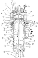
- FIGS. 1 to 7 is a setting device 1 greatly simplified in a longitudinal section in various operating conditions and views shown. That in the FIGS. 1 to 7 Setting device 1 shown can be operated with a fuel gas or with a vaporizable liquid fuel.
- the setting device 1 comprises a housing 3 with a master cylinder 5, which limits a main combustion chamber 6.
- the main combustion chamber 6 can be supplied via an inlet device 8 gas and / or air.
- the main combustion chamber 6 is assigned an ignition device 9.
- the driving piston 10 comprises a piston rod 11, which starts from a piston head 12.
- a the piston head or piston plate 12 facing away from setting 14 of the piston rod 11 is arranged in a bolt guide, which serves to guide fasteners, which are also referred to as bolts.
- FIG. 7 the setting end 14 of the piston rod 11 of the drive piston 10 is shown cut off.
- the bolt guide with the piston rod 11 of the drive piston 10 disposed therein is also referred to as a setter.
- a fastener such as a nail, bolts or the like, are driven into a (not shown) underground.
- the setting tool 1 is pressed with his pin guide to the ground and triggered.
- a switch (not shown) is used, which is also called a trigger switch.
- the switch is provided, for example, on a (also not shown) handle of the setting device 1.
- FIGS. 1 to 7 a setting direction indicated.
- the driving piston 10 is out of his in FIG. 1 illustrated initial position corresponding to an upper or rear dead center, moved to an end position corresponding to a lower or front dead center.
- a movement of the driving piston 10 in the FIGS. 1 to 7 to the right is limited by a housing-fixed piston stop 16.
- the piston stop 16 By the piston stop 16, the top dead center of the driving piston 10 is defined.
- the piston stop 16 may be combined with a magnetic device 17.
- the magnetic device 17 serves, for example, the driving piston 10 with a predetermined holding force in his in FIG. 1 to keep the initial position shown.
- a movement of the driving piston 10 to the left is limited by stop and / or damping elements 28, 29.
- the stop and / or damping elements 28 represent a buffer 110.
- the piston head 12 comprises a first piston surface 21, which faces the main combustion chamber 6.
- the prechamber 25 represents a pre-combustion chamber to which an ignition device 26 and an inlet device 27 are assigned.
- the stop and / or damping elements 28, 29 are arranged in the antechamber 25.
- a fuel gas-air mixture is supplied, which is ignited by means of the ignition device 26 in the pre-chamber 25.
- the pre-chamber cylinder 24 comprises passage openings 31, 32, which allow, for example, the exit of exhaust gases from the pre-chamber 25.
- the passage openings 31, 32 can be closed by a control device 30 as needed.
- the control device 30 comprises a control sleeve 34, the passage openings 37, 38 has.
- control sleeve 34 has substantially the shape of a straight circular cylinder jacket and is in FIG. 11 shown in detail.
- overflow openings 41, 42 are provided between the antechamber 25 and the main combustion chamber 6 overflow openings 41, 42 are provided.
- the overflow openings 41, 42 are each assigned a valve device 43, 44.
- the valve devices 43, 44 are, for example, valve flaps which allow passage of a ignited air-fuel mixture from the prechamber 25 into the main combustion chamber 6.
- the control device 30 comprises a control pressure surface 45, which is connected in terms of pressure with the main combustion chamber 6.
- the control pressure surface 45 is designed as an annular surface 46, which faces radially outside of the prechamber cylinder 24 of the main combustion chamber 6.
- the control pressure surface 45 is mechanically coupled to the control sleeve 34 via a coupling element 48.
- the coupling element 48 is designed as a slider 50, which in the FIGS. 1 to 7 in the horizontal direction movable back and forth on the antechamber cylinder 24 is guided. At one in the FIGS. 1 to 7 right end 51 of the slider 50 is designed as an annular surface 46 control pressure surface 45 is provided. At one in the FIGS. 1 to 7 left end 52 of the slider 50, the control sleeve 34 is attached.
- the control device 30 further comprises spring devices 54, 55, which are designed, for example, as helical compression springs.
- the in the FIGS. 1 to 7 Left ends of the spring means 54, 55 is associated with a housing fixed stop 56, 57 respectively.
- the housing-fixed stops 56, 57 are provided on the prechamber cylinder 24.
- the spring devices 54, 55 are clamped between the housing-fixed stops 56, 57 and the right end 51 of the slider 50 with the control pressure surface 45.
- the slider 50 via the spring means 54, 55 supported on the housing-fixed stops 56, 57.
- Not pressed state means that the setting end 14 of the drive piston 10 is not acted upon by a bolt or a fastener with a compressive force which is to be driven into a subsoil.
- pressing the bolt setting tool 1 is pressed with a tool tip of the bolt setting tool 1 against the ground.
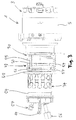
- the main combustion chamber 6 is bounded by a combustion chamber sleeve 84 which is displaceable in the axial direction limited to allow flushing of the main combustion chamber 6.
- a fan 80 is arranged in the main combustion chamber 6.
- FIG. 2 is the position of the combustion chamber sleeve 84 so that the fan 80 indicated by arrows air flow 81, 82 of the rear of the device, ie the in FIG. 2 right side, generated by the main combustion chamber 6 in the environment.
- the air flow 81, 82 exhaust gases are transported out of the main combustion chamber 6 after a setting process.
- the air flow 81, 82 ensures cooling of the main combustion chamber 6.
- the bolt gun 1 is shown in the pressed state.
- the setting end 14 which is also referred to as a tool tip, is pressed against a fastening element.
- the combustion chamber sleeve 84 to the rear ie in FIG. 4 to the right, moved, as in FIG. 4 is indicated by an arrow 83.
- the movement 83 of the combustion chamber sleeve 84 to the rear the main combustion chamber 6 is closed from the environment.
- fuel gas is injected via the inlet device 27 into the prechamber 25 and via the inlet device 8 into the main combustion chamber 6.
- the fan 80 rotates in the main combustion chamber 6.
- the ignition of the gas mixture is initiated by the ignition device 26 associated with the pre-chamber 25 in the vicinity of the buffer 110.
- a laminar flame front spreads, which migrates from the side of the buffer 110 in the direction of the main combustion chamber 6, ie in FIG. 4 to the right.
- the propagating laminar flame front pushes unburned air / fuel mixture into the main combustion chamber 6 at a high pressure.
- the overflow from the pre-chamber 25 in the main combustion chamber 6 via the overflow openings 41, 42 with open valve means 43, 44th Die Valve means 43, 44 are, for example, designed as check valves which release the overflow openings 41, 42, which are also referred to as overflow openings, during spreading of the laminar flame front.
- the flame can over-ignite via the check valves in the main combustion chamber 6, whereby the main chamber combustion is introduced into the main combustion chamber 6.
- FIG. 6 is indicated by a symbol 86, the main chamber ignition in the main combustion chamber 6.
- the prechamber pressure escaping from the prechamber 25 via the opened vent connections 108, 109 is in FIG. 6 indicated by arrows 91 to 94.
- the pressure relief connections 108, 109 are also referred to as exhaust ports. Via the pressure relief connections or exhaust openings 108, 109, the pre-chamber pressure at the main chamber ignition 86 can escape.
- the driving piston 10 sets in the main chamber ignition 86 at high speed in motion and executes a settlement.
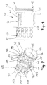
- FIG. 7 the bolt setting device 1 is shown in a longitudinal return at a thermal return of the drive piston 10.
- a main chamber residual pressure was blown off via the pressure relief connection 109. This has the consequence that the main combustion chamber pressure in the main combustion chamber 6 drops to ambient pressure and the control sleeve 34 pressure-controlled the exhaust ports or pressure relief connections 108, 109 closes again.
- the Vorscheinlass 140 is advantageously associated with a one-way check valve.
- the check valve includes a relatively large leaflet which, while allowing fresh air to be drawn into the prechamber 25, but in the reverse direction, prevents undesirable outflow of pressurized fuel and air mixture from the prechamber 25 into the environment.
- FIG. 7 When lifting the bolt gun 1 with the setting end 14, the FIG. 7 is shown cut off, from the ground, the combustion chamber sleeve 84 is again shifted so that the main combustion chamber 6 can be flushed with ambient air, as in FIG. 2 indicated by the arrows 81 and 82. Subsequently, a new setting cycle can be started.
- the control device 30 comprises the control sleeve 34, which is connected via the coupling element 48 with a coupling sleeve 100.
- a coupling sleeve 100 At a free end of the coupling sleeve 100, so in FIG. 9 right end of the coupling sleeve 100, which is designed as an annular surface 46 control pressure surface 45 is provided.
- the coupling sleeve 100 is fixedly connected to a connecting flange 105 via slide rods 101, 102, 103, which partially represent the slider 50.
- the connecting flange 105 connects the control sleeve 34 with the slide rods 101 to 103.
- the slide rods 101 to 103 are connected to the coupling sleeve 100 via a connecting flange 98.
- Each slide rod 101 to 103 is associated with a spring device 54, 55 designed as a compression spring.
- the spring devices 54, 55 are clamped in the installed state of the control device 30 between the connecting flange 98 and the housing-fixed stops 56, 57 on the prechamber cylinder 24.
- the control sleeve 34 serves to the passage openings 31, 32; 117, 118 release in the pre-chamber cylinder 24 as needed, as in FIG. 6 is indicated by the arrows 91 to 94.
- the control sleeve 34, the passage openings 37, 38; 117, 118, for opening the vent connections 108, 109 with the Through openings 31, 32; 111, 112 are brought into the pre-chamber cylinder 24 to cover.
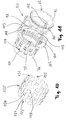
- the check valve device 120 comprises valve elements 121 to 123, which are interconnected by a connecting ring body 124.
- Each of the valve elements 121 to 123 comprises two closing elements 127, 128, the passage openings 37; 118 of the two pressure relief connections 108; 109 are assigned.
- valve elements 121 to 123 with the closing elements 127, 128 are integrally formed from spring steel.
- the production of the valve elements 121 to 123 with the closing elements 127, 128 takes place, for example, by laser beam cutting.
- the connecting ring body 124 may also be made by laser cutting from a spring steel material.
- Bolt setting tool 1 shown is additionally equipped with a detection device 180, which serves to detect a position, a starting position or a piston malfunction of the driving piston 10 before a settlement.
- the detection device 180 is indicated only by a rectangle and arranged, for example, between an inner housing and an outer housing of the setting device 1.
- the detection device 180 comprises piston end position sensors 181, 182 and is connected to an electronic control unit 184 in terms of control.
- the control connections are indicated by dashed lines.
- the piston end sensor 181 is arranged on one of the main combustion chamber 6 opposite end of the prechamber cylinder 24.
- the piston end sensor 182 is combined with a magnetic device 17 which provides magnetic restraint for the driving piston 10 in its in FIG. 12 represents initial situation shown.
- the setting device 1 is also equipped with a sensor device 185.
- the sensor device 185 is used to detect environmental influences, such as an ambient temperature or an ambient pressure.
- the sensor device 185 is also connected to the electronic control unit 184 in terms of control.
- the electronic control unit 184 is also connected to an injection device 187 via a control line 186 in terms of control.
- the injection device 187 is part of the inlet device 27, via which fuel gas is injected into the pre-chamber 25.
- the electronic control 184 is moreover control-wise via a control line 188 connected to an injector 189.
- the injection device 189 is part of the inlet device 8, via which fuel gas is injected into the main combustion chamber 6.
- the piston end sensor 182 is designed, for example, as a proximity switch or contact switch. With the piston end sensor 182 can be detected in a simple manner, whether the driving piston 10 is in its defined starting position, the in FIG. 12 is shown.
- the piston end position sensor 181 can advantageously also be embodied as a piston position sensor or as a sensor for detecting the piston travel of the drive piston 10.
- the sensor 181 can detect whether the drive piston 10 has more or less than a predetermined error. For example, it can be detected with the sensor 181 whether the driving piston 10 has a fault of more or less than, for example, thirty percent.
- the sensor 181 is designed as a sensor for detecting the piston travel, then with the sensor 181, the initial position of the piston can be detected.
- the sensor 181 is designed, for example, as a Hall sensor and interacts with sensors with grooves which are provided on or in the piston rod 11 of the driving piston 10.
- the electronic control unit 184 With the aid of the electronic control unit 184, it is distinguished how large a piston malfunction detected by the detection device 180 is. If the piston malfunction is small enough to operate the setting tool 1 in the usual way, then an injection takes place in both chambers 25, 6 and the ignition takes place initially only in the antechamber 25. The ignition in the pre-chamber 25 is through the Ignition 26 triggered, which is associated with the pre-chamber 25.
- the injection quantity is adapted in at least one of the chambers 25, 6.
- the piston malfunction detected by the detection device 180 is small enough to operate the setting tool 1 in the usual way but exceeds a certain first limit value
- the injection quantity is adapted in at least one of the chambers 25, 6.
- the fuel remains Air mixture in both chambers 25, 6 approximately stoichiometric and can be ignited well.
- the setting device 1 is ignited only in the main combustion chamber 6. Before that, an appropriate amount of fuel gas is injected into the main combustion chamber 6. In the antechamber 25 is not injected at a too large piston malfunction.
- FIG. 12 Setting device 1 shown provides the following advantages over the known prior art: higher reliability, because the in FIG. 12 setting device ensures that the pre-chamber and the main chamber combustion is reliable by the stoichiometric mixture preparation. There are no ignition failures or weak burns, which ultimately lead to lower energy. In the setting device 1 in FIG. 12 it is ensured that the unit energy remains constant by controlling the injection quantity. Of course, this does not apply to the case when ignited for piston failure elimination only in the main combustion chamber 6.
- Setting tool 1 shown the advantage that a larger piston malfunction is detected automatically. Then it can be triggered automatically with less energy and only with a main chamber ignition. As a result, the driving piston 10 comes in its defined starting position and the setting tool 1 works normally again at the next setting cycle.
Landscapes
- Engineering & Computer Science (AREA)
- Chemical & Material Sciences (AREA)
- Combustion & Propulsion (AREA)
- Mechanical Engineering (AREA)
- Portable Nailing Machines And Staplers (AREA)
- Ignition Installations For Internal Combustion Engines (AREA)
- Combustion Methods Of Internal-Combustion Engines (AREA)
- Combined Controls Of Internal Combustion Engines (AREA)
Priority Applications (7)
| Application Number | Priority Date | Filing Date | Title |
|---|---|---|---|
| EP15201899.0A EP3184255A1 (fr) | 2015-12-22 | 2015-12-22 | Outil de scellement a moteur thermique et procede de fonctionnement d'un outil de scellement |
| TW105137073A TWI659812B (zh) | 2015-12-22 | 2016-11-14 | 燃燒動力驅動的安置設備、其操作方法及具有執行該方法的程式指令的電腦程式產品 |
| PCT/EP2016/081917 WO2017108787A1 (fr) | 2015-12-22 | 2016-12-20 | Outil de pose actionné par la pression d'une combustion et procédé pour faire fonctionner un outil de pose de ce type |
| US16/062,141 US11103987B2 (en) | 2015-12-22 | 2016-12-20 | Fuel-operated firing device and method for operating a firing device of this type |
| JP2018532708A JP6599011B2 (ja) | 2015-12-22 | 2016-12-20 | 燃焼力駆動打ち込み装置、及び、そのような打ち込み装置の作動方法 |
| EP16822977.1A EP3393716B1 (fr) | 2015-12-22 | 2016-12-20 | Procede de fonctionnement d'un outil de scellement |
| CN201680075963.5A CN108472796B (zh) | 2015-12-22 | 2016-12-20 | 燃烧动力驱动的安置设备和用于运行这种安置设备的方法 |
Applications Claiming Priority (1)
| Application Number | Priority Date | Filing Date | Title |
|---|---|---|---|
| EP15201899.0A EP3184255A1 (fr) | 2015-12-22 | 2015-12-22 | Outil de scellement a moteur thermique et procede de fonctionnement d'un outil de scellement |
Publications (1)
| Publication Number | Publication Date |
|---|---|
| EP3184255A1 true EP3184255A1 (fr) | 2017-06-28 |
Family
ID=54936912
Family Applications (2)
| Application Number | Title | Priority Date | Filing Date |
|---|---|---|---|
| EP15201899.0A Withdrawn EP3184255A1 (fr) | 2015-12-22 | 2015-12-22 | Outil de scellement a moteur thermique et procede de fonctionnement d'un outil de scellement |
| EP16822977.1A Active EP3393716B1 (fr) | 2015-12-22 | 2016-12-20 | Procede de fonctionnement d'un outil de scellement |
Family Applications After (1)
| Application Number | Title | Priority Date | Filing Date |
|---|---|---|---|
| EP16822977.1A Active EP3393716B1 (fr) | 2015-12-22 | 2016-12-20 | Procede de fonctionnement d'un outil de scellement |
Country Status (6)
| Country | Link |
|---|---|
| US (1) | US11103987B2 (fr) |
| EP (2) | EP3184255A1 (fr) |
| JP (1) | JP6599011B2 (fr) |
| CN (1) | CN108472796B (fr) |
| TW (1) | TWI659812B (fr) |
| WO (1) | WO2017108787A1 (fr) |
Families Citing this family (2)
| Publication number | Priority date | Publication date | Assignee | Title |
|---|---|---|---|---|
| EP3184253A1 (fr) | 2015-12-22 | 2017-06-28 | HILTI Aktiengesellschaft | Outil de scellement a moteur thermique et procede de fonctionnement d'un outil de scellement |
| EP3184254A1 (fr) | 2015-12-22 | 2017-06-28 | HILTI Aktiengesellschaft | Outil de scellement a moteur thermique et procede de fonctionnement d'un outil de scellement |
Citations (6)
| Publication number | Priority date | Publication date | Assignee | Title |
|---|---|---|---|---|
| US4913331A (en) * | 1988-10-21 | 1990-04-03 | Hitachi Koki Company, Ltd. | Internal-combustion piston driving apparatus having a decompression channel |
| DE4243617A1 (de) | 1992-12-22 | 1994-06-23 | Hilti Ag | Tragbares, brennkraftbetriebenes Arbeitsgerät, insbesondere Setzgerät |
| DE10232035A1 (de) * | 2002-07-16 | 2004-01-29 | Hilti Ag | Brennkraftbetriebenes Setzgerät |
| US20040144357A1 (en) * | 2003-01-24 | 2004-07-29 | Adams Joseph S. | Multiple-front combustion chamber system with a fuel/air management system |
| DE10327191B3 (de) * | 2003-06-17 | 2004-12-16 | Hilti Ag | Setzgerät |
| EP2106883A1 (fr) * | 2008-04-01 | 2009-10-07 | HILTI Aktiengesellschaft | Appareil de pose fonctionnant avec des combustibles |
Family Cites Families (24)
| Publication number | Priority date | Publication date | Assignee | Title |
|---|---|---|---|---|
| JPS63147012A (ja) * | 1986-12-05 | 1988-06-20 | Hitachi Koki Co Ltd | 内燃式ピストン駆動装置の掃気装置 |
| DE4010517B4 (de) | 1990-04-02 | 2004-04-08 | Hilti Ag | Gasbetriebenes Arbeitsgerät |
| DE19950349B4 (de) * | 1999-10-19 | 2006-07-27 | Hilti Ag | Setzgerät für Befestigungselemente |
| DE50109817D1 (de) * | 2001-07-19 | 2006-06-22 | Hilti Ag | Bolzensetzgerät mit Setztiefenregelung |
| US6582204B2 (en) * | 2001-09-06 | 2003-06-24 | The United States Of America As Represented By The Administrator Of The U.S. Enviromental Protection Agency | Fully-controlled, free-piston engine |
| US6671163B2 (en) | 2002-02-04 | 2003-12-30 | Illinois Tool Works Inc. | Integrated spark and switch unit for combustion fastener driving tool |
| JP3925793B2 (ja) | 2002-08-09 | 2007-06-06 | 日立工機株式会社 | 燃焼式打込み工具 |
| CN1273270C (zh) * | 2002-08-09 | 2006-09-06 | 日立工机株式会社 | 以燃气为动力的射钉枪 |
| DE10259567A1 (de) * | 2002-12-19 | 2004-07-01 | Hilti Ag | Brennkraftbetriebenes Setzgerät |
| DE10260703A1 (de) | 2002-12-23 | 2004-07-01 | Hilti Ag | Brennkraftbetriebenes Setzgerät |
| DE10260702B4 (de) * | 2002-12-23 | 2014-01-30 | Hilti Aktiengesellschaft | Brennkraftbetriebenes Setzgerät |
| US6755159B1 (en) | 2003-01-20 | 2004-06-29 | Illinois Tool Works Inc. | Valve mechanisms for elongated combustion chambers |
| US6948459B1 (en) * | 2004-08-28 | 2005-09-27 | Ford Global Technologies, Llc | Position sensing for a free piston engine |
| JP2008018513A (ja) * | 2006-07-14 | 2008-01-31 | Makita Corp | 燃焼式作業工具 |
| US8302832B2 (en) | 2007-06-21 | 2012-11-06 | Illinois Tool Works Inc. | Fastener feeder delay for fastener driving tool |
| US8276798B2 (en) * | 2007-06-21 | 2012-10-02 | Illinois Tool Works Inc. | Feeder mechanism retention device for fastener driving tool |
| DE102009041824A1 (de) * | 2009-09-18 | 2011-03-24 | Hilti Aktiengesellschaft | Vorrichtung zur Übertragung von Energie auf ein Befestigungselement |
| DE102009041828A1 (de) * | 2009-09-18 | 2011-03-24 | Hilti Aktiengesellschaft | Vorrichtung zur Übertragung von Energie auf ein Befestigungselement |
| DE102010030098A1 (de) * | 2010-06-15 | 2011-12-15 | Hilti Aktiengesellschaft | Eintreibvorrichtung |
| US8636185B2 (en) * | 2010-11-15 | 2014-01-28 | Illinois Tool Works Inc. | Fastener advance delay for fastener driving tool |
| EP2826601A1 (fr) | 2013-07-16 | 2015-01-21 | HILTI Aktiengesellschaft | Procédé de commande et machine-outil manuelle |
| EP3308907B1 (fr) * | 2015-06-10 | 2021-04-14 | Koki Holdings Co., Ltd. | Machine d'entraînement |
| EP3184254A1 (fr) | 2015-12-22 | 2017-06-28 | HILTI Aktiengesellschaft | Outil de scellement a moteur thermique et procede de fonctionnement d'un outil de scellement |
| EP3184253A1 (fr) | 2015-12-22 | 2017-06-28 | HILTI Aktiengesellschaft | Outil de scellement a moteur thermique et procede de fonctionnement d'un outil de scellement |
-
2015
- 2015-12-22 EP EP15201899.0A patent/EP3184255A1/fr not_active Withdrawn
-
2016
- 2016-11-14 TW TW105137073A patent/TWI659812B/zh active
- 2016-12-20 EP EP16822977.1A patent/EP3393716B1/fr active Active
- 2016-12-20 US US16/062,141 patent/US11103987B2/en active Active
- 2016-12-20 CN CN201680075963.5A patent/CN108472796B/zh active Active
- 2016-12-20 JP JP2018532708A patent/JP6599011B2/ja active Active
- 2016-12-20 WO PCT/EP2016/081917 patent/WO2017108787A1/fr active Application Filing
Patent Citations (6)
| Publication number | Priority date | Publication date | Assignee | Title |
|---|---|---|---|---|
| US4913331A (en) * | 1988-10-21 | 1990-04-03 | Hitachi Koki Company, Ltd. | Internal-combustion piston driving apparatus having a decompression channel |
| DE4243617A1 (de) | 1992-12-22 | 1994-06-23 | Hilti Ag | Tragbares, brennkraftbetriebenes Arbeitsgerät, insbesondere Setzgerät |
| DE10232035A1 (de) * | 2002-07-16 | 2004-01-29 | Hilti Ag | Brennkraftbetriebenes Setzgerät |
| US20040144357A1 (en) * | 2003-01-24 | 2004-07-29 | Adams Joseph S. | Multiple-front combustion chamber system with a fuel/air management system |
| DE10327191B3 (de) * | 2003-06-17 | 2004-12-16 | Hilti Ag | Setzgerät |
| EP2106883A1 (fr) * | 2008-04-01 | 2009-10-07 | HILTI Aktiengesellschaft | Appareil de pose fonctionnant avec des combustibles |
Also Published As
| Publication number | Publication date |
|---|---|
| US20180370004A1 (en) | 2018-12-27 |
| JP6599011B2 (ja) | 2019-10-30 |
| EP3393716A1 (fr) | 2018-10-31 |
| JP2018538480A (ja) | 2018-12-27 |
| TWI659812B (zh) | 2019-05-21 |
| CN108472796B (zh) | 2022-04-05 |
| US11103987B2 (en) | 2021-08-31 |
| TW201726329A (zh) | 2017-08-01 |
| CN108472796A (zh) | 2018-08-31 |
| EP3393716B1 (fr) | 2021-02-03 |
| WO2017108787A1 (fr) | 2017-06-29 |
Similar Documents
| Publication | Publication Date | Title |
|---|---|---|
| DE10232035B4 (de) | Brennkraftbetriebenes Setzgerät | |
| DE602005005790T2 (de) | Brennkammersteuerung für brennkraftbetriebenes werkzeug zum eintreiben von befestigungselementen | |
| DE19962598C2 (de) | Tragbares, brennkraftbetriebenes Arbeitsgerät, insbesondere Setzgerät für Befestigungselemente und Verfahren zu seiner Betriebssteuerung | |
| DE19950349A1 (de) | Setzgerät für Befestigungselemente | |
| EP3446833A1 (fr) | Cloueur à air comprimé pourvu de dispositif de soupape de sécurité | |
| EP3083150B1 (fr) | Appareil de travail | |
| EP3393716B1 (fr) | Procede de fonctionnement d'un outil de scellement | |
| DE10135031C2 (de) | Tragbares, brennkraftbetriebenes Arbeitsgerät, insbesondere Setzgerät für Befestigungselemente | |
| EP3393714B1 (fr) | Outil de scellement a moteur thermique et procede de fonctionnement d'un outil de scellement | |
| EP3666469A1 (fr) | Cloueur pneumatique doté d'un dispositif de sécurité | |
| EP3393717B1 (fr) | Outil de scellement a moteur thermique et procede de fonctionnement d'un outil de scellement | |
| WO2017108777A1 (fr) | Appareil de pose actionné par combustion interne et procédé pour faire fonctionner un appareil de pose de ce type | |
| EP3471921B1 (fr) | Cloueur a air comprime comprenant un declenchement sequentiel et par contact | |
| EP0805003B1 (fr) | Appareil de scellement de chevilles actionné par la poudre | |
| DE602004009737T2 (de) | Verbrennungsmotorwerkzeug | |
| EP2767636A1 (fr) | Mouton diesel | |
| EP3393711B1 (fr) | Outil de scellement a moteur thermique et procede de fonctionnement d'un outil de scellement | |
| DE102005014644A1 (de) | Brennstoffzuführsystem für eine Brennkraftmaschine | |
| DE102013101550A1 (de) | Dieselramme | |
| WO2017108751A1 (fr) | Appareil de pose à commande par un moteur à combustion interne et procédé de fonctionnment d'un tel appareil de pose | |
| DE671049C (de) | Brennkraftramme, insbesondere fuer Strassenbauzwecke | |
| EP2924170A1 (fr) | Marteau batteur | |
| DE112021000062T5 (de) | Eintreibvorrichtung für befestigungselemente | |
| DE1484504C (de) | Zweitaktdieselramme mit Anlaß zundhilfe | |
| DE102007057275A1 (de) | Pulsationstriebwerk mit innenliegender Treibstoff-Einspritzung |
Legal Events
| Date | Code | Title | Description |
|---|---|---|---|
| PUAI | Public reference made under article 153(3) epc to a published international application that has entered the european phase |
Free format text: ORIGINAL CODE: 0009012 |
|
| AK | Designated contracting states |
Kind code of ref document: A1 Designated state(s): AL AT BE BG CH CY CZ DE DK EE ES FI FR GB GR HR HU IE IS IT LI LT LU LV MC MK MT NL NO PL PT RO RS SE SI SK SM TR |
|
| AX | Request for extension of the european patent |
Extension state: BA ME |
|
| STAA | Information on the status of an ep patent application or granted ep patent |
Free format text: STATUS: THE APPLICATION IS DEEMED TO BE WITHDRAWN |
|
| 18D | Application deemed to be withdrawn |
Effective date: 20180103 |