EP3165495B1 - Turmdrehkran - Google Patents
Turmdrehkran Download PDFInfo
- Publication number
- EP3165495B1 EP3165495B1 EP16201390.8A EP16201390A EP3165495B1 EP 3165495 B1 EP3165495 B1 EP 3165495B1 EP 16201390 A EP16201390 A EP 16201390A EP 3165495 B1 EP3165495 B1 EP 3165495B1
- Authority
- EP
- European Patent Office
- Prior art keywords
- trolley
- boom
- hook block
- transport position
- block
- Prior art date
- Legal status (The legal status is an assumption and is not a legal conclusion. Google has not performed a legal analysis and makes no representation as to the accuracy of the status listed.)
- Active
Links
- 238000010276 construction Methods 0.000 description 3
Images


Classifications
-
- B—PERFORMING OPERATIONS; TRANSPORTING
- B66—HOISTING; LIFTING; HAULING
- B66C—CRANES; LOAD-ENGAGING ELEMENTS OR DEVICES FOR CRANES, CAPSTANS, WINCHES, OR TACKLES
- B66C23/00—Cranes comprising essentially a beam, boom, or triangular structure acting as a cantilever and mounted for translatory of swinging movements in vertical or horizontal planes or a combination of such movements, e.g. jib-cranes, derricks, tower cranes
- B66C23/18—Cranes comprising essentially a beam, boom, or triangular structure acting as a cantilever and mounted for translatory of swinging movements in vertical or horizontal planes or a combination of such movements, e.g. jib-cranes, derricks, tower cranes specially adapted for use in particular purposes
- B66C23/26—Cranes comprising essentially a beam, boom, or triangular structure acting as a cantilever and mounted for translatory of swinging movements in vertical or horizontal planes or a combination of such movements, e.g. jib-cranes, derricks, tower cranes specially adapted for use in particular purposes for use on building sites; constructed, e.g. with separable parts, to facilitate rapid assembly or dismantling, for operation at successively higher levels, for transport by road or rail
- B66C23/34—Self-erecting cranes, i.e. with hoisting gear adapted for crane erection purposes
- B66C23/344—Self-erecting cranes, i.e. with hoisting gear adapted for crane erection purposes adapted for transport purposes
Definitions
- the invention relates to a tower crane according to the preamble of claim 1.
- folding jib cranes which are arranged on a chassis and there can be transferred from a transport position to an operating position and vice versa.
- These tower cranes have a one-part or multi-part tower, a multi-part boom and a trolley and a hook block.
- the boom parts can be connected to one another in a displaceable and / or articulated manner, with the boom parts being displaceably and / or articulated to one another in the transport position in such a way that they lie next to and / or one above the other in the transport position on the trolley.
- the trolley In the transport position, the trolley is usually secured to the boom with the hook block.
- the boom pivot piece in the transport position, the boom pivot piece is folded onto the telescopic tower and the outer boom piece is folded back onto the boom pivot piece.
- the boom pivot piece, the boom center piece and the outer boom piece are put together in a zigzag shape.
- the articulated connection between the lower and upper chords having and consisting of lattice girders jib pieces can each consist in such a way that these are articulated to their lower or upper chords.
- the trolley and the associated hook block In the transport position of a folding jib crane, the trolley and the associated hook block must also be accommodated and secured.
- the trolley In the transport position of a folding jib crane, the trolley and the associated hook block must also be accommodated and secured.
- the trolley it is known from the prior art to arrange the trolley on a short intermediate piece which is vertical in the transport position at the rear end of the crane.
- the trolley is arranged and secured on the center piece of a three-part folded boom, but the boom tip, which is placed on the center piece, must be shortened by the space required by the trolley, as the boom tip would otherwise collide with the protruding trolley.
- the hook block and trolley must be secured separately in their transport position using locking elements specially provided for this purpose.
- These locking elements are usually operated manually. This in turn means that when the tower crane is erected automatically, the corresponding securing elements must be released manually by an operator and secured again accordingly when the tower crane is folded up.
- the DE 698 11 002 T2 discloses a tower crane according to the preamble of claim 1.
- This crane has two boom parts connected to one another via an intermediate element, which are superimposed in a transport position, the assembly of trolley and hook block being arranged on the outside of the intermediate element in the transport position.
- the object of the invention is to create a tower crane according to the invention which has a maximum tower height and a maximum boom length with regard to the permissible transport length.
- a tower crane that can be moved from a transport position to an operating position and vice versa and which has a one-part or multi-part tower, a multi-part boom, a trolley and a hook block comprising a bottle
- the tower parts and the boom parts are movable and / or are articulated with one another and the boom parts are displaceably and / or articulated with one another in such a way that the boom parts lie next to one another and / or one above the other in the transport position
- the trolley and the hook block are arranged between two or more boom parts in the transport position and as Assembly with the boom part on which the trolley is arranged can be locked.
- the structural unit between the trolley and hook block is formed according to the invention in that an opening is made in the trolley between hoisting rope pulleys, into which the hook block can be moved in the transport position.
- the locking takes place according to the invention in that a holding means is arranged on the hook block which can be brought into engagement with a cantilever-side counter-holding means for locking, the holding means on the hook block being designed as a cross yoke and the counter-holding means as a hook element or vice versa.
- the trolley with the hook block is automatically compatible with the pulling of the hoist rope, which is guided over the hoist rope pulleys of the trolley and those of the hook block, to form a unit that is used for engagement with the Counter-holding means is movable, the bottle of the hook block entering the opening by pulling the hoisting rope
- the individual parts of the multi-part boom can have approximately the same length, so that the maximum lengths of the boom parts possible due to the permissible transport length in the transport position can be used.
- a maximum tower height and a maximum boom length can be achieved for a given transport length.
- the length of one of the tower parts or jib parts lying on top of one another or next to one another in the transport position does not have to be shortened due to the correspondingly arranged trolley or hook block. It is possible in the same way within the scope of the invention to design the corresponding boom parts as a three-belt or as a four-belt boom system.
- At least one third of the bottle of the hook block can be received in the opening in a particularly advantageous manner.
- the opening in the trolley is designed as a shaft in such a way that the shaft wall positively encloses the bottle of the hook block in the transport position.
- the trolley is also secured in the transport position at the same time.
- the visible tower crane 1 is designed as a folding jib crane which is mounted on the undercarriage 10 of a vehicle 12.
- the tower crane 1 is in the Figures 1a and 1b shown in an intermediate position, shortly before reaching the final transport position.
- the tower crane consists, as can be seen from the Figure 1a results from a two-part tower 2 with the telescopic tower parts 2a and 2b.
- a three-part boom 3 consisting of a boom pivot piece 3a, a boom center piece 3b and a boom tip 3c is placed on top of one another in a zigzag shape.
- the three boom parts 3a, 3b and 3c are each connected to one another in an articulated manner.
- the boom parts 3a, 3b and 3c are as in FIG Figure 1b recognizable as three-chord boom systems. As in the Figures 1b and especially in Figure 3 the boom parts 3b and 3c are shown tilted laterally with respect to the boom part 3a via a corresponding articulated connection, so that the on the undercarriage 10 available space can be used as compactly as possible. For further details, see the EP 1 084 983 B1 expressly referred.
- FIG 2 the boom parts 3 are shown.
- the trolley 4 is arranged in the position in which it remains in the transport position T.
- the trolley 4 is largely of conventional construction and has hoisting rope pulleys 116, 117 over which a hoisting rope 103 is guided in the usual way.
- An opening 110 in the form of a shaft 112 is formed between the hoisting rope pulleys 116 and 117.
- the shaft 112 has a shaft wall 112a, on which the bottle 113 of the hook block 5 dips into the shaft 112 and rests against it.
- the load hook 111 is arranged on the hook block 5. In the submerged state of the hook block 5, the hook block 5 forms a structural unit 106 with the trolley 4.
- This entire structural unit 106 is locked in the transport position T in the in FIG Figure 2 in the manner shown and thus secured.
- the locking device 109 consists of a holding means 109a which is arranged on the hook block 5 and which can be brought into engagement with a counter holding means 109b, as in FIG Figure 2 shown.
- the holding means 109a is a transverse yoke 114, which is fastened to the bottle 113 of the hook block 5 via two parallel plates 115, referred to as a sword.
- This cross yoke stands with the one designed as a hook Counter-holding means 109b in the transport position T in the in Figure 2 engaged manner.
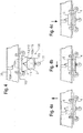
- FIG. 4 shows the hook block 5 in its operating position.
- Figure 4c Transport position T shown transferred.
- the trolley is combined with the hook block 5 to form a structural unit 106. This takes place automatically by pulling the hoisting rope 103, which is guided over the hoisting rope pulleys (116, 117) of the trolley 4 and those of the hook block 5.
- the hoisting rope 103 By appropriately tightening the hoisting rope 103, the hook block 5 is moved from the position according to FIG Figure 4 transferred to the position according to Figure 4a.
- the bottle 113 of the hook block 5 enters the opening 110, designed as a shaft 112, in the trolley 4 and is supported there on the shaft wall 112a.
- a structural unit 106 is formed from the hook block 5 and the trolley 4.
- the trolley 4 is therefore moved in the direction of the arrow according to FIG. 4a.
- the assembly 106 formed is then shown in the direction of the arrow Figure 4b moved until the yoke 114 engages in the counter holding means 109b designed as a hook.
- Figure 4c be fixed by lowering the hook block 5 in the direction of the arrow in the hook 109b.
- the entire structural unit 106 is secured in the transport position T.
- the available transport length for the boom can be fully utilized.
- the trolley and load hook are combined as a unit mounted on the boom part in such a way that the construction of the entire tower crane is not influenced by this and thus an optimal use of the length of the tower is given.
Landscapes
- Engineering & Computer Science (AREA)
- Transportation (AREA)
- Structural Engineering (AREA)
- Mechanical Engineering (AREA)
- Jib Cranes (AREA)
Description
- Die Erfindung betrifft einen Turmdrehkran nach dem Oberbegriff des Anspruchs 1.
- Es sind bereits Turmdrehkräne der eingangs genannten Art in unterschiedlichen Ausführungsformen bekannt.
- So sind beispielsweise aus der
EP 1 084 983 B1 sogenannte Faltauslegerkräne bekannt, die auf einem Fahrwerk angeordnet sind und dort von einer Transportstellung in eine Betriebsstellung und umgekehrt überführbar sind. Diese Turmdrehkräne weisen einen ein- oder mehrteiligen Turm, einen mehrteiligen Ausleger und eine Laufkatze sowie eine Hakenflasche auf. Die Auslegerteile können verschieblich und/oder gelenkig miteinander verbunden sein, wobei in der Transportstellung die Auslegerteile derart verschieblich und/oder gelenkig miteinander verbunden sind, dass sie in der Transportstellung auf dem Transportwagen nebeneinander und/oder übereinander liegen. In der Transportstellung ist die Laufkatze üblicherweise mit der Hakenflasche an dem Ausleger gesichert. - In der
EP 1 084 983 B1 ist im Einzelnen beschrieben, wie in der Transportstellung das Auslegeranlenkstück an den einteleskopierbaren Turm angeklappt und das äußere Auslegerstück auf das Auslegeranlenkstück zurückgeklappt ist. Bei einem dreiteiligen Ausleger werden das Auslegeranlenkstück, das Auslegermittelstück und das äußere Auslegerstück zick-zack-förmig zusammengelegt. Dabei kann die gelenkige Verbindung zwischen den Unter- und Obergurte aufweisenden und aus Gitterträgern bestehenden Auslegerstücken jeweils in der Weise bestehen, dass diese gelenkig an ihren Unter- oder Obergurten verbunden sind. - In der Transportstellung eines Faltauslegerkranes muß auch die Laufkatze und die zugehörige Hakenflasche untergebracht und gesichert werden. Hierzu ist es aus dem Stand der Technik bekannt, die Laufkatze an einem kurzen, in Transportstellung senkrechten Zwischenstück am hinteren Ende des Krans anzuordnen. In anderen Ausführungsformen wird die Laufkatze am Mittelstück eines dreiteiligen zusammengeklappten Auslegers angeordnet und gesichert, wobei allerdings die Auslegerspitze, die auf dem Mittelstück abgelegt wird, um den Platzbedarf der Laufkatze gekürzt werden muß, da die Auslegerspitze sonst mit der hervorstehenden Laufkatze kollidieren würde.
- Darüber hinaus müssen Hakenflasche und Laufkatze separat in ihrer Transportposition über eigens hierfür vorgesehene Verriegelungselemente gesichert werden. Diese Verriegelungselemente werden in der Regel manuell betätigt. Das wiederum bedeutet, dass bei einem automatischen Aufrichten des Turmdrehkrans die entsprechenden Sicherungselemente manuell von einer Bedienperson gelöst und beim Zusammenfalten des Turmdrehkrans entsprechend wieder gesichert werden müssen.
- Die
DE 698 11 002 T2 offenbart einen Turmdrehkran, gemäß dem Oberbegriff des Anspruchs 1. Dieser Kran hat zwei über ein Zwischenelement miteinander verbundenen Auslegerteilen, welche in einer Transportstellung übereinander liegen, wobei die Baueinheit aus Laufkatze und Hakenflasche in der Transportstellung außen an dem Zwischenelement angeordnet ist. - Aufgabe der Erfindung ist es nun, einen erfindungsgemäßen Turmdrehkran zu schaffen, welcher hinsichtlich der zulässigen Transportlänge eine maximale Turmhöhe und eine maximale Auslegerlänge aufweist.
- Diese Aufgabe wird ausgehend von einem gattungsgemäßen Turmdrehkran durch die Kombination der Merkmale des Anspruchs 1 gelöst.
- Entsprechend der Lösung werden bei einem Turmdrehkran, der von einer Transportstellung in eine Betriebsstellung und umgekehrt überführbar ist und der einen ein- oder mehrteiligen Turm, einen mehrteiligen Ausleger, eine Laufkatze und eine eine Flasche umfassende Hakenflasche aufweist, wobei die Turmteile und die Auslegerteile verschieblich und/oder gelenkig miteinander verbunden sind und die Auslegerteile verschieblich und/oder gelenkig derart miteinander verbunden sind, dass die Auslegerteile in der Transportstellung nebeneinander und/oder übereinander liegen, und wobei die Laufkatze und die Hakenflasche in der Transportstellung zwischen zwei oder mehreren Auslegerteilen angeordnet und als Baueinheit mit dem Auslegerteil, an dem die Laufkatze angeordnet ist, verriegelbar sind.
- Die Baueinheit zwischen Laufkatze und Hakenflasche wird erfindungsgemäß dadurch gebildet, dass in der Laufkatze zwischen Hubseilrollen ein Durchbruch ausgenommen ist, in den die Hakenflasche in der Transportstellung einfahrbar ist.
- Die Verriegelung erfolgt erfindungsgemäß dadurch, dass an der Hakenflasche ein Haltemittel angeordnet ist, das zur Verriegelung mit einem auslegerseitigen Gegenhaltemittel in Eingriff bringbar ist, wobei das Haltemittel an der Hakenflasche als Querjoch und das Gegenhaltemittel als Hakenelement ausgebildet ist oder umgekehrt.
- Erfindungsgemäß ist die Laufkatze mit der Hakenflasche automatisch durch Anziehen des Hubseils, welches über die Hubseilrollen der Laufkatze und diejenigen der Hakenflasche geführt ist, zu einer Baueinheit vereinbar, die zum Eingriff mit dem Gegenhaltemittel bewegbar ist, wobei durch Anziehen des Hubseils die Flasche der Hakenflasche in den Durchbruch eintritt
Aufgrund dieser erfindungsgemäßen Ausführung können die einzelnen Teile des mehrteiligen Auslegers ungefähr die gleiche Länge aufweisen, so dass die durch die zulässige Transportlänge in der Transportstellung möglichen Maximallängen der Auslegerteile ausgenutzt werden können. Somit kann für eine vorgegebene Transportlänge eine maximale Turmhöhe und eine maximale Auslegerlänge erzielt werden. Es muß nach der erfindungsgemäßen Lösung die Länge eines der in Transportstellung aufeinander bzw. nebeneinander liegenden Turmteile bzw. Auslegerteile nicht aufgrund der entsprechend angeordneten Laufkatze oder der Hakenflasche verkürzt werden. Dabei ist es im Rahmen der Erfindung in gleicher Weise möglich, die entsprechenden Auslegerteile als Dreigurt- oder auch als Viergurtauslegersystem auszuführen. - Besondere Ausgestaltungen der Erfindung ergeben sich aus den sich an den Hauptanspruch anschließenden Unteransprüchen.
- Besonders vorteilhaft ist die Flasche der Hakenflasche zu wenigstens einem Drittel in dem Durchbruch aufnehmbar.
- Besonders vorteilhaft ist es, wenn der Durchbruch in der Laufkatze derart als Schacht ausgebildet ist, dass die Schachtwand die Flasche der Hakenflasche in der Transportstellung formschlüssig umschließt. In diesem Fall wird durch die Festlegung der Hakenflasche mittels des Haltemittels gleichzeitig auch die Laufkatze in der Transportstellung gesichert.
- Weitere Merkmale, Einzelheiten und Vorteile der Erfindung werden anhand eines in der Zeichnung dargestellten Ausführungsbeispiels näher erläutert. Es zeigen:
- Figur 1a und Figur 1b:
- eine Seiten- bzw. Rückansicht eines erfindungsgemäßen Turmdrehkrans während des Zusammenfaltens in die Transportstellung,
- Figur 2:
- ein Detail der
Figur 1a , - Figur 3:
- eine vergrößerte Darstellung der
Figur 1b , d. h. die Rückansicht des Turmdrehkrans in einer Stellung während des Zusammenfaltens und in seiner Endstellung und - Figur 4, 4a, 4b, 4c:
- ein Detail des Turmdrehkrans gemäß
Figur 1 während des Festlegens und Sicherns der Laufkatze und der Hakenflasche beim Überführen des Turmdrehkrans in seine Transportstellung. - Der aus den
Figuren 1a und 1b ersichtliche Turmdrehkran 1 ist in der hier dargestellten Ausführungsform als Faltauslegerkran ausgebildet, der auf dem Unterwagen 10 eines Fahrzeuges 12 montiert ist. Der Turmdrehkran 1 ist in denFiguren 1a und 1b in einer Zwischenstellung, kurz vor Erreichen der endgültigen Transportstellung dargestellt. Der Turmdrehkran besteht, wie sich aus derFigur 1a ergibt, aus einem zweiteiligen Turm 2 mit den austeleskopierbaren Turmteilen 2a und 2b. An der Spitze des austeleskopierbaren Turmteils 2b ist ein dreiteiliger Ausleger 3 bestehend aus einem Auslegeranlenkstück 3a, einem Auslegermittelstück 3b und einer Auslegerspitze 3c in Zick-Zack-Form aufeinandergelegt. Die drei Auslegerteile 3a, 3b und 3c sind jeweils gelenkig miteinander verbunden. - Die Auslegerteile 3a, 3b und 3c sind, wie in
Figur 1b zu erkennen als Dreigurt-Auslegersysteme ausgebildet. Wie in denFiguren 1b und insbesondere inFigur 3 dargestellt sind die Auslegerteile 3b und 3c über eine entsprechende Gelenkverbindung seitlich gegenüber dem Auslegerteil 3a gekippt, so dass der auf dem Unterwagen 10 verfügbare Raum möglichst kompakt genutzt werden kann. Bezüglich weiterer Details wird auf dieEP 1 084 983 B1 ausdrücklich verwiesen. - Von besonderer Bedeutung im Rahmen der vorliegenden Erfindung ist die Ausgestaltung und Anordnung von Laufkatze 4 und Hakenflasche 5 in der Transportstellung T. Zu dem Aufbau von Laufkatze 4 und Hakenflasche 5 verweisen wir insbesondere auf das Detail A in
Figur 1a , welches vergrößert inFigur 2 wiedergegeben ist. - In
Figur 2 sind die Auslegerteile 3 dargestellt. Am Auslegermittelteil 3b ist die Laufkatze 4 in der Position angeordnet, in der sie in der Transportstellung T verweilt. Die Laufkatze 4 ist weitgehend konventionell aufgebaut und weist Hubseilrollen 116, 117 auf, über die ein Hubseil 103 in üblicher Weise geführt ist. Zwischen den Hubseilrollen 116 und 117 ist ein Durchbruch 110 in Form eines Schachtes 112 ausgebildet. Der Schacht 112 weist eine Schachtwand 112a auf, an der beim Einfahren in den Schacht 112 die Flasche 113 der Hakenflasche 5 eintaucht und an dieser anliegt. An der Hakenflasche 5 ist der Lasthaken 111 angeordnet. Im eingetauchten Zustand der Hakenflasche 5 bildet die Hakenflasche 5 mit der Laufkatze 4 eine Baueinheit 106. - Diese gesamte Baueinheit 106 wird über eine Verriegelungseinrichtung 109 in der Transportstellung T in der in
Figur 2 dargestellten Art und Weise festgelegt und so gesichert. - Die Verriegelungseinrichtung 109 besteht aus einem an der Hakenflasche 5 angeordneten Haltemittel 109a, das mit einem Gegenhaltemittel 109b in Eingriff bringbar ist, wie in
Figur 2 dargestellt. - Bei dem Haltemittel 109a handelt es sich um ein Querjoch 114, welches über zwei parallel angeordnete, als Schwert bezeichnete Bleche 115 an der Flasche 113 der Hakenflasche 5 befestigt ist. Dieses Querjoch steht mit dem als Haken ausgebildeten Gegenhaltemittel 109b in der Transportstellung T in der in
Figur 2 dargestellten Art und Weise in Eingriff. - Anhand der
Figur 4 kann dargestellt werden, wie die Laufkatze 4 und die Hakenflasche 5 in besonders einfacher Art und Weise automatisch in die Transportstellung T überführt werden können. DieFigur 4 zeigt die Hakenflasche 5 in ihrer Betriebsstellung. Im Verlauf derFiguren 4a, 4b und 4c wird diese in die gemäßFigur 4c dargestellte Transportstellung T überführt. Hierzu wird die Laufkatze mit der Hakenflasche 5 zu einer Baueinheit 106 vereint. Dies erfolgt automatisch durch Anziehen des Hubseils 103, welches über die Hubseilrollen (116, 117) der Laufkatze 4 und diejenigen der Hakenflasche 5 geführt wird. Durch entsprechendes Anziehen des Hubseils 103 wird die Hakenflasche 5 aus der Position gemäßFigur 4 in die Position gemäß Figur 4a überführt. Dabei tritt die Flasche 113 der Hakenflasche 5 in den als Schacht 112 gestalteten Durchbruch 110 in der Laufkatze 4 ein und stützt sich dort an der Schachtwand 112a ab. Hierdurch wird eine Baueinheit 106 aus der Hakenflasche 5 und der Laufkatze 4 gebildet. Die Laufkatze 4 wird also in Pfeilrichtung gemäß Figur 4a bewegt. Anschließend wird die gebildete Baueinheit 106 in Pfeilrichtung gemäßFigur 4b bewegt, bis das Joch 114 in das als Haken ausgebildete Gegenhaltemittel 109b eingreift. Anschließend kann, wie inFigur 4c durch entsprechendes Absenken der Hakenflasche 5 in Pfeilrichtung im Haken 109b fixiert werden. Hierdurch wird die gesamte Baueinheit 106 in der Transportstellung T gesichert. - In der in
Figur 2 dargestellten Ausführungsvariante wird der Stauraum 6 zur Aufnahme der aus Hakenflasche 5 und Laufkatze 4 bestehenden Baueinheit dadurch erreicht, dass das Auslegerteil 3a zu seiner Spitze hin verjüngt ist. Hierdurch ergibt sich ein Zwischenraum, in dem die Baueinheit 106 unterbringbar ist. Dabei taucht der Haken 111 der Hakenflasche 5 zwischen den beiden Gurten des Auslegerteils 3c hindurch (vgl.Figur 2 ). - Durch die Unterbringung der Laufkatze 4 und der Hakenflasche 5 zwischen den Auslegerteilen kann die zur Verfügung stehende Transportlänge für den Ausleger voll ausgenutzt werden. Laufkatze und Lasthaken werden gemeinsam als Baueinheit am Auslegerteil so gelagert, dass die Konstruktion des gesamten Turmdrehkrans hiervon nicht beeinflußt wird und somit auch eine optimale Längenausnutzung des Turms gegeben ist.
Claims (3)
- Turmdrehkran (1), der von einer Transportstellung (T) in eine Betriebsstellung (B) und umgekehrt überführbar ist, mit einem ein- oder mehrteiligen Turm (2), einem mehrteiligen Ausleger (3), einer Laufkatze (4) und einer eine Flasche (113) umfassenden Hakenflasche (5), wobei die Turmteile (2a, 2b) und die Auslegerteile (3a, 3b, 3c) verschieblich und/ oder gelenkig miteinander verbunden sind und die Auslegerteile (3a, 3b, 3c) verschieblich und/oder gelenkig derart miteinander verbunden sind, dass die Auslegerteile (3a, 3b, 3c) in der Transportstellung (T) nebeneinander und/ oder übereinander liegen und wobei die Laufkatze (4) und die Hakenflasche (5) als Baueinheit in der Transportstellung (T) mit dem Auslegerteil (3a, 3b, 3c), an dem die Laufkatze (4) angeordnet ist, verriegelbar ist,
dadurch gekennzeichnet,
dass die Laufkatze (4) und die Hakenflasche (5) in der Transportstellung (T) zwischen zwei oder mehreren Auslegerteilen (3a, 3b, 3c) angeordnet sind, dass ein Durchbruch (110) zwischen Hubseilrollen (116, 117) der Laufkatze (4) angeordnet ist, und dass an der Hakenflasche (5) ein Haltemittel (109a) angeordnet ist, das zur Verriegelung mit einem auslegerseitigen Gegenhaltemittel (109b) in Eingriff bringbar ist, wobei die Laufkatze (4) mit der Hakenflasche (5) automatisch durch Anziehen des Hubseils (103), welches über die Hubseilrollen (116, 117) der Laufkatze (4) und diejenigen der Hakenflasche (5) geführt ist, zu einer Baueinheit (106) vereinbar ist, die zum Eingriff mit dem Gegenhaltemittel (109a) bewegbar ist, wobei durch Anziehen des Hubseils (103) die Flasche (113) der Hakenflasche (5) in den Durchbruch (110) eintritt, und wobei das Haltemittel (109a) an der Hakenflasche (5) als Querjoch (114) und das Gegenhaltemittel (109b) als Hakenelement ausgebildet ist oder umgekehrt. - Turmdrehkran nach Anspruch 1, dadurch gekennzeichnet, dass die Flasche (113) der Hakenflasche (5) zu wenigstens einem Drittel in dem Durchbruch (110) aufnehmbar ist.
- Turmdrehkran nach einem der vorhergehenden Ansprüche, dadurch gekennzeichnet, dass der Durchbruch (110) in der Laufkatze (4) derart als Schacht (112) ausgebildet ist, dass die Schachtwand (102a) die Flasche (113) der Hakenflasche (5) in der Transportstellung (T) formschlüssig umschließt.
Applications Claiming Priority (2)
| Application Number | Priority Date | Filing Date | Title |
|---|---|---|---|
| DE102009005237A DE102009005237A1 (de) | 2009-01-21 | 2009-01-21 | Turmdrehkran |
| EP09014123.5A EP2210851B1 (de) | 2009-01-21 | 2009-11-11 | Turmdrehkran |
Related Parent Applications (2)
| Application Number | Title | Priority Date | Filing Date |
|---|---|---|---|
| EP09014123.5A Division EP2210851B1 (de) | 2009-01-21 | 2009-11-11 | Turmdrehkran |
| EP09014123.5A Division-Into EP2210851B1 (de) | 2009-01-21 | 2009-11-11 | Turmdrehkran |
Publications (2)
| Publication Number | Publication Date |
|---|---|
| EP3165495A1 EP3165495A1 (de) | 2017-05-10 |
| EP3165495B1 true EP3165495B1 (de) | 2021-02-17 |
Family
ID=42115762
Family Applications (2)
| Application Number | Title | Priority Date | Filing Date |
|---|---|---|---|
| EP09014123.5A Active EP2210851B1 (de) | 2009-01-21 | 2009-11-11 | Turmdrehkran |
| EP16201390.8A Active EP3165495B1 (de) | 2009-01-21 | 2009-11-11 | Turmdrehkran |
Family Applications Before (1)
| Application Number | Title | Priority Date | Filing Date |
|---|---|---|---|
| EP09014123.5A Active EP2210851B1 (de) | 2009-01-21 | 2009-11-11 | Turmdrehkran |
Country Status (4)
| Country | Link |
|---|---|
| EP (2) | EP2210851B1 (de) |
| CN (1) | CN101870436B (de) |
| DE (1) | DE102009005237A1 (de) |
| ES (2) | ES2867856T3 (de) |
Families Citing this family (5)
| Publication number | Priority date | Publication date | Assignee | Title |
|---|---|---|---|---|
| ITTO20110887A1 (it) * | 2011-10-04 | 2013-04-05 | Gru Dalbe Srl | Base di supporto per gru auto-montante e gru auto-montante comprendente una base di supporto siffatta |
| ITTO20110886A1 (it) * | 2011-10-04 | 2013-04-05 | Gru Dalbe Srl | Gru auto-montante |
| DE102012018111A1 (de) | 2012-09-13 | 2014-03-13 | Liebherr-Werk Biberach Gmbh | Turmdrehkran |
| DE102013009564A1 (de) * | 2013-06-06 | 2014-12-11 | Liebherr-Werk Biberach Gmbh | Vorrichtung zum Verbinden von Profilelementen |
| DE102018214847B3 (de) | 2018-08-31 | 2019-12-24 | Tadano Faun Gmbh | Haltevorrichtung für eine Hakenflaschenablage eines Mobilkrans, Oberwagen für einen Mobilkran und Mobilkran |
Family Cites Families (13)
| Publication number | Priority date | Publication date | Assignee | Title |
|---|---|---|---|---|
| FR85559E (fr) * | 1964-03-24 | 1965-09-03 | Ponton Freres & Cie Ets | Perfectionnement aux grues télescopiques de chantier en vue d'en augmenter la hauteur du mât |
| AT294370B (de) * | 1969-10-22 | 1971-11-25 | Wetzel Kg | Turmdrehkran |
| DE2053450C2 (de) * | 1970-10-30 | 1973-01-18 | Fa Wilhelm Reich | Turmkran |
| SU738985A1 (ru) * | 1977-06-17 | 1980-06-05 | Всесоюзный конструкторско-технологический институт по механизации монтажных и специальных строительных работ | Способ монтажа-демонтажа башенного телескопического крана и устройство дл его осуществлени |
| DE4344733A1 (de) * | 1993-12-27 | 1995-06-29 | Liebherr Werk Biberach Gmbh | Turmdrehkran |
| CN2247650Y (zh) * | 1995-03-07 | 1997-02-19 | 桂林市建工机械厂 | 一种可折叠的塔式起重机 |
| FR2765564B1 (fr) * | 1997-07-02 | 1999-08-27 | Potain Sa | Mature pliable en trois elements avec dispositif de pliage/depliage pour grue a tour |
| FR2792627B1 (fr) * | 1999-04-23 | 2001-06-01 | Potain Sa | Grue avec fleche a fonctions multiples |
| ATE307777T1 (de) | 1999-09-17 | 2005-11-15 | Liebherr Werk Biberach Gmbh | Turmdrehkran |
| DE29916410U1 (de) * | 1999-09-17 | 2000-04-27 | Liebherr-Werk Biberach GmbH, 88400 Biberach | Gelenkig miteinander verbundene, im Querschnitt dreieckige Gitterträger |
| EP1172323A1 (de) * | 2000-07-11 | 2002-01-16 | Jean-Marc Yerly | Kran mit aus Gliedern bestehendem Kranarm |
| US7341158B2 (en) * | 2004-01-09 | 2008-03-11 | Kobelco Cranes Co., Ltd. | Traveling crane and assembling/disassembling method thereof |
| KR100846209B1 (ko) * | 2007-04-12 | 2008-07-14 | 케이엔에프중공업주식회사 | 타워크레인용 트롤리 |
-
2009
- 2009-01-21 DE DE102009005237A patent/DE102009005237A1/de not_active Ceased
- 2009-11-11 EP EP09014123.5A patent/EP2210851B1/de active Active
- 2009-11-11 ES ES16201390T patent/ES2867856T3/es active Active
- 2009-11-11 EP EP16201390.8A patent/EP3165495B1/de active Active
- 2009-11-11 ES ES09014123T patent/ES2744359T3/es active Active
-
2010
- 2010-01-21 CN CN201010003361.3A patent/CN101870436B/zh active Active
Non-Patent Citations (1)
| Title |
|---|
| None * |
Also Published As
| Publication number | Publication date |
|---|---|
| ES2744359T3 (es) | 2020-02-24 |
| EP2210851A3 (de) | 2013-05-29 |
| EP3165495A1 (de) | 2017-05-10 |
| DE102009005237A1 (de) | 2010-07-29 |
| ES2867856T3 (es) | 2021-10-21 |
| CN101870436A (zh) | 2010-10-27 |
| EP2210851A2 (de) | 2010-07-28 |
| EP2210851B1 (de) | 2019-06-05 |
| CN101870436B (zh) | 2015-03-25 |
Similar Documents
| Publication | Publication Date | Title |
|---|---|---|
| DE102005049606B4 (de) | Fahrzeugkran mit Zusatzausleger und Verfahren zur Demontage des Hilfsauslegers | |
| DE102007051539C5 (de) | Verfahren zum Aufrichten eines Kranauslegers | |
| EP3165495B1 (de) | Turmdrehkran | |
| DE202008004663U1 (de) | Gittermastkran und Gittermastausleger | |
| DE102011016015B4 (de) | Gittermastkran und Gittermastausleger | |
| EP2465809A1 (de) | Teleskopiersystem für Kranausleger und Zusatzausleger | |
| DE102008062648B4 (de) | Teleskopierbarer Kranausleger | |
| EP1939135B1 (de) | Kranfahrzeug | |
| DE202017107301U1 (de) | Turmdrehkran | |
| DE102010023275B4 (de) | Verfahren zum Verfahren von Großkranen im aufgerüsteten System und System zum Durchführen dieses Verfahrens | |
| EP2199247B1 (de) | Drehverbindung | |
| DE102007058553A1 (de) | Seitliche Abspannung für einen Gitterausleger eines Kranes | |
| DE102015001619B4 (de) | Auslegersystem für einen Mobilkran sowie Mobilkran | |
| DE102013113957A1 (de) | Batteriewechseladapter | |
| DE202007012764U1 (de) | Auslegerkran, Hilfsausleger und Zwischenstück | |
| DE102015002626A1 (de) | Teleskopausleger eines Krans und Verfahren zu seiner Abspannung, sowie zum Aufrichten von Teleskopverlängerungen | |
| EP2805083B1 (de) | Seilendverbindung und seilhülse für eine seilendverbindung | |
| DE102017000389A1 (de) | Kranausleger, Kran mit einem solchen Kranausleger und Verfahren zum Anbringen einer Abspannstütze an einem solchen Kranausleger | |
| DE69714696T2 (de) | Teleskopmast für einen Turmkran | |
| DE202004002424U1 (de) | Derrickkran | |
| DE202008015659U1 (de) | Kranspitze für einen Ladekran | |
| DE202016100483U1 (de) | Fahrzeug-Leichtkran mit teleskopierbarer Klappspitze | |
| DE102011119656B4 (de) | Fahrzeugkran | |
| DE102007009402A1 (de) | Wippausleger-Turmdrehkran | |
| DE102005035234B3 (de) | Als Teleskopanordnung ausgestalteter Fahrzeugausleger |
Legal Events
| Date | Code | Title | Description |
|---|---|---|---|
| PUAI | Public reference made under article 153(3) epc to a published international application that has entered the european phase |
Free format text: ORIGINAL CODE: 0009012 |
|
| STAA | Information on the status of an ep patent application or granted ep patent |
Free format text: STATUS: THE APPLICATION HAS BEEN PUBLISHED |
|
| AC | Divisional application: reference to earlier application |
Ref document number: 2210851 Country of ref document: EP Kind code of ref document: P |
|
| AK | Designated contracting states |
Kind code of ref document: A1 Designated state(s): AT BE BG CH CY CZ DE DK EE ES FI FR GB GR HR HU IE IS IT LI LT LU LV MC MK MT NL NO PL PT RO SE SI SK SM TR |
|
| STAA | Information on the status of an ep patent application or granted ep patent |
Free format text: STATUS: REQUEST FOR EXAMINATION WAS MADE |
|
| 17P | Request for examination filed |
Effective date: 20171110 |
|
| STAA | Information on the status of an ep patent application or granted ep patent |
Free format text: STATUS: EXAMINATION IS IN PROGRESS |
|
| 17Q | First examination report despatched |
Effective date: 20180420 |
|
| GRAP | Despatch of communication of intention to grant a patent |
Free format text: ORIGINAL CODE: EPIDOSNIGR1 |
|
| STAA | Information on the status of an ep patent application or granted ep patent |
Free format text: STATUS: GRANT OF PATENT IS INTENDED |
|
| INTG | Intention to grant announced |
Effective date: 20200922 |
|
| GRAS | Grant fee paid |
Free format text: ORIGINAL CODE: EPIDOSNIGR3 |
|
| GRAA | (expected) grant |
Free format text: ORIGINAL CODE: 0009210 |
|
| STAA | Information on the status of an ep patent application or granted ep patent |
Free format text: STATUS: THE PATENT HAS BEEN GRANTED |
|
| AC | Divisional application: reference to earlier application |
Ref document number: 2210851 Country of ref document: EP Kind code of ref document: P |
|
| AK | Designated contracting states |
Kind code of ref document: B1 Designated state(s): AT BE BG CH CY CZ DE DK EE ES FI FR GB GR HR HU IE IS IT LI LT LU LV MC MK MT NL NO PL PT RO SE SI SK SM TR |
|
| REG | Reference to a national code |
Ref country code: GB Ref legal event code: FG4D Free format text: NOT ENGLISH |
|
| REG | Reference to a national code |
Ref country code: CH Ref legal event code: EP |
|
| REG | Reference to a national code |
Ref country code: DE Ref legal event code: R096 Ref document number: 502009016322 Country of ref document: DE |
|
| REG | Reference to a national code |
Ref country code: AT Ref legal event code: REF Ref document number: 1361208 Country of ref document: AT Kind code of ref document: T Effective date: 20210315 |
|
| REG | Reference to a national code |
Ref country code: IE Ref legal event code: FG4D Free format text: LANGUAGE OF EP DOCUMENT: GERMAN |
|
| REG | Reference to a national code |
Ref country code: CH Ref legal event code: NV Representative=s name: KELLER SCHNEIDER PATENT- UND MARKENANWAELTE AG, CH |
|
| REG | Reference to a national code |
Ref country code: NL Ref legal event code: FP |
|
| REG | Reference to a national code |
Ref country code: LT Ref legal event code: MG9D |
|
| PG25 | Lapsed in a contracting state [announced via postgrant information from national office to epo] |
Ref country code: HR Free format text: LAPSE BECAUSE OF FAILURE TO SUBMIT A TRANSLATION OF THE DESCRIPTION OR TO PAY THE FEE WITHIN THE PRESCRIBED TIME-LIMIT Effective date: 20210217 Ref country code: FI Free format text: LAPSE BECAUSE OF FAILURE TO SUBMIT A TRANSLATION OF THE DESCRIPTION OR TO PAY THE FEE WITHIN THE PRESCRIBED TIME-LIMIT Effective date: 20210217 Ref country code: GR Free format text: LAPSE BECAUSE OF FAILURE TO SUBMIT A TRANSLATION OF THE DESCRIPTION OR TO PAY THE FEE WITHIN THE PRESCRIBED TIME-LIMIT Effective date: 20210518 Ref country code: PT Free format text: LAPSE BECAUSE OF FAILURE TO SUBMIT A TRANSLATION OF THE DESCRIPTION OR TO PAY THE FEE WITHIN THE PRESCRIBED TIME-LIMIT Effective date: 20210617 Ref country code: NO Free format text: LAPSE BECAUSE OF FAILURE TO SUBMIT A TRANSLATION OF THE DESCRIPTION OR TO PAY THE FEE WITHIN THE PRESCRIBED TIME-LIMIT Effective date: 20210517 Ref country code: BG Free format text: LAPSE BECAUSE OF FAILURE TO SUBMIT A TRANSLATION OF THE DESCRIPTION OR TO PAY THE FEE WITHIN THE PRESCRIBED TIME-LIMIT Effective date: 20210517 Ref country code: LT Free format text: LAPSE BECAUSE OF FAILURE TO SUBMIT A TRANSLATION OF THE DESCRIPTION OR TO PAY THE FEE WITHIN THE PRESCRIBED TIME-LIMIT Effective date: 20210217 |
|
| PG25 | Lapsed in a contracting state [announced via postgrant information from national office to epo] |
Ref country code: SE Free format text: LAPSE BECAUSE OF FAILURE TO SUBMIT A TRANSLATION OF THE DESCRIPTION OR TO PAY THE FEE WITHIN THE PRESCRIBED TIME-LIMIT Effective date: 20210217 Ref country code: PL Free format text: LAPSE BECAUSE OF FAILURE TO SUBMIT A TRANSLATION OF THE DESCRIPTION OR TO PAY THE FEE WITHIN THE PRESCRIBED TIME-LIMIT Effective date: 20210217 Ref country code: LV Free format text: LAPSE BECAUSE OF FAILURE TO SUBMIT A TRANSLATION OF THE DESCRIPTION OR TO PAY THE FEE WITHIN THE PRESCRIBED TIME-LIMIT Effective date: 20210217 |
|
| PG25 | Lapsed in a contracting state [announced via postgrant information from national office to epo] |
Ref country code: IS Free format text: LAPSE BECAUSE OF FAILURE TO SUBMIT A TRANSLATION OF THE DESCRIPTION OR TO PAY THE FEE WITHIN THE PRESCRIBED TIME-LIMIT Effective date: 20210617 |
|
| REG | Reference to a national code |
Ref country code: ES Ref legal event code: FG2A Ref document number: 2867856 Country of ref document: ES Kind code of ref document: T3 Effective date: 20211021 |
|
| PG25 | Lapsed in a contracting state [announced via postgrant information from national office to epo] |
Ref country code: EE Free format text: LAPSE BECAUSE OF FAILURE TO SUBMIT A TRANSLATION OF THE DESCRIPTION OR TO PAY THE FEE WITHIN THE PRESCRIBED TIME-LIMIT Effective date: 20210217 Ref country code: CZ Free format text: LAPSE BECAUSE OF FAILURE TO SUBMIT A TRANSLATION OF THE DESCRIPTION OR TO PAY THE FEE WITHIN THE PRESCRIBED TIME-LIMIT Effective date: 20210217 Ref country code: SM Free format text: LAPSE BECAUSE OF FAILURE TO SUBMIT A TRANSLATION OF THE DESCRIPTION OR TO PAY THE FEE WITHIN THE PRESCRIBED TIME-LIMIT Effective date: 20210217 |
|
| REG | Reference to a national code |
Ref country code: DE Ref legal event code: R097 Ref document number: 502009016322 Country of ref document: DE |
|
| PG25 | Lapsed in a contracting state [announced via postgrant information from national office to epo] |
Ref country code: SK Free format text: LAPSE BECAUSE OF FAILURE TO SUBMIT A TRANSLATION OF THE DESCRIPTION OR TO PAY THE FEE WITHIN THE PRESCRIBED TIME-LIMIT Effective date: 20210217 Ref country code: RO Free format text: LAPSE BECAUSE OF FAILURE TO SUBMIT A TRANSLATION OF THE DESCRIPTION OR TO PAY THE FEE WITHIN THE PRESCRIBED TIME-LIMIT Effective date: 20210217 Ref country code: DK Free format text: LAPSE BECAUSE OF FAILURE TO SUBMIT A TRANSLATION OF THE DESCRIPTION OR TO PAY THE FEE WITHIN THE PRESCRIBED TIME-LIMIT Effective date: 20210217 |
|
| PLBE | No opposition filed within time limit |
Free format text: ORIGINAL CODE: 0009261 |
|
| STAA | Information on the status of an ep patent application or granted ep patent |
Free format text: STATUS: NO OPPOSITION FILED WITHIN TIME LIMIT |
|
| 26N | No opposition filed |
Effective date: 20211118 |
|
| PG25 | Lapsed in a contracting state [announced via postgrant information from national office to epo] |
Ref country code: SI Free format text: LAPSE BECAUSE OF FAILURE TO SUBMIT A TRANSLATION OF THE DESCRIPTION OR TO PAY THE FEE WITHIN THE PRESCRIBED TIME-LIMIT Effective date: 20210217 |
|
| PG25 | Lapsed in a contracting state [announced via postgrant information from national office to epo] |
Ref country code: IS Free format text: LAPSE BECAUSE OF FAILURE TO SUBMIT A TRANSLATION OF THE DESCRIPTION OR TO PAY THE FEE WITHIN THE PRESCRIBED TIME-LIMIT Effective date: 20210617 |
|
| PG25 | Lapsed in a contracting state [announced via postgrant information from national office to epo] |
Ref country code: MC Free format text: LAPSE BECAUSE OF FAILURE TO SUBMIT A TRANSLATION OF THE DESCRIPTION OR TO PAY THE FEE WITHIN THE PRESCRIBED TIME-LIMIT Effective date: 20210217 |
|
| PG25 | Lapsed in a contracting state [announced via postgrant information from national office to epo] |
Ref country code: LU Free format text: LAPSE BECAUSE OF NON-PAYMENT OF DUE FEES Effective date: 20211111 Ref country code: BE Free format text: LAPSE BECAUSE OF NON-PAYMENT OF DUE FEES Effective date: 20211130 |
|
| REG | Reference to a national code |
Ref country code: BE Ref legal event code: MM Effective date: 20211130 |
|
| PG25 | Lapsed in a contracting state [announced via postgrant information from national office to epo] |
Ref country code: IE Free format text: LAPSE BECAUSE OF NON-PAYMENT OF DUE FEES Effective date: 20211111 |
|
| PGFP | Annual fee paid to national office [announced via postgrant information from national office to epo] |
Ref country code: IT Payment date: 20221130 Year of fee payment: 14 Ref country code: GB Payment date: 20221124 Year of fee payment: 14 Ref country code: ES Payment date: 20221201 Year of fee payment: 14 |
|
| PG25 | Lapsed in a contracting state [announced via postgrant information from national office to epo] |
Ref country code: HU Free format text: LAPSE BECAUSE OF FAILURE TO SUBMIT A TRANSLATION OF THE DESCRIPTION OR TO PAY THE FEE WITHIN THE PRESCRIBED TIME-LIMIT; INVALID AB INITIO Effective date: 20091111 Ref country code: CY Free format text: LAPSE BECAUSE OF FAILURE TO SUBMIT A TRANSLATION OF THE DESCRIPTION OR TO PAY THE FEE WITHIN THE PRESCRIBED TIME-LIMIT Effective date: 20210217 |
|
| P01 | Opt-out of the competence of the unified patent court (upc) registered |
Effective date: 20230630 |
|
| PGFP | Annual fee paid to national office [announced via postgrant information from national office to epo] |
Ref country code: NL Payment date: 20231127 Year of fee payment: 15 |
|
| PGFP | Annual fee paid to national office [announced via postgrant information from national office to epo] |
Ref country code: FR Payment date: 20231127 Year of fee payment: 15 Ref country code: DE Payment date: 20231121 Year of fee payment: 15 Ref country code: CH Payment date: 20231201 Year of fee payment: 15 Ref country code: AT Payment date: 20231124 Year of fee payment: 15 |
|
| PG25 | Lapsed in a contracting state [announced via postgrant information from national office to epo] |
Ref country code: MK Free format text: LAPSE BECAUSE OF FAILURE TO SUBMIT A TRANSLATION OF THE DESCRIPTION OR TO PAY THE FEE WITHIN THE PRESCRIBED TIME-LIMIT Effective date: 20210217 |
|
| GBPC | Gb: european patent ceased through non-payment of renewal fee |
Effective date: 20231111 |