EP3162573B1 - Ink jet recording apparatus - Google Patents
Ink jet recording apparatus Download PDFInfo
- Publication number
- EP3162573B1 EP3162573B1 EP16196454.9A EP16196454A EP3162573B1 EP 3162573 B1 EP3162573 B1 EP 3162573B1 EP 16196454 A EP16196454 A EP 16196454A EP 3162573 B1 EP3162573 B1 EP 3162573B1
- Authority
- EP
- European Patent Office
- Prior art keywords
- ink
- cover member
- tank
- jet recording
- recording apparatus
- Prior art date
- Legal status (The legal status is an assumption and is not a legal conclusion. Google has not performed a legal analysis and makes no representation as to the accuracy of the status listed.)
- Active
Links
Images






Classifications
-
- B—PERFORMING OPERATIONS; TRANSPORTING
- B41—PRINTING; LINING MACHINES; TYPEWRITERS; STAMPS
- B41J—TYPEWRITERS; SELECTIVE PRINTING MECHANISMS, i.e. MECHANISMS PRINTING OTHERWISE THAN FROM A FORME; CORRECTION OF TYPOGRAPHICAL ERRORS
- B41J2/00—Typewriters or selective printing mechanisms characterised by the printing or marking process for which they are designed
- B41J2/005—Typewriters or selective printing mechanisms characterised by the printing or marking process for which they are designed characterised by bringing liquid or particles selectively into contact with a printing material
- B41J2/01—Ink jet
-
- B—PERFORMING OPERATIONS; TRANSPORTING
- B41—PRINTING; LINING MACHINES; TYPEWRITERS; STAMPS
- B41J—TYPEWRITERS; SELECTIVE PRINTING MECHANISMS, i.e. MECHANISMS PRINTING OTHERWISE THAN FROM A FORME; CORRECTION OF TYPOGRAPHICAL ERRORS
- B41J2/00—Typewriters or selective printing mechanisms characterised by the printing or marking process for which they are designed
- B41J2/005—Typewriters or selective printing mechanisms characterised by the printing or marking process for which they are designed characterised by bringing liquid or particles selectively into contact with a printing material
- B41J2/01—Ink jet
- B41J2/17—Ink jet characterised by ink handling
- B41J2/175—Ink supply systems ; Circuit parts therefor
- B41J2/17596—Ink pumps, ink valves
-
- B—PERFORMING OPERATIONS; TRANSPORTING
- B41—PRINTING; LINING MACHINES; TYPEWRITERS; STAMPS
- B41J—TYPEWRITERS; SELECTIVE PRINTING MECHANISMS, i.e. MECHANISMS PRINTING OTHERWISE THAN FROM A FORME; CORRECTION OF TYPOGRAPHICAL ERRORS
- B41J2/00—Typewriters or selective printing mechanisms characterised by the printing or marking process for which they are designed
- B41J2/005—Typewriters or selective printing mechanisms characterised by the printing or marking process for which they are designed characterised by bringing liquid or particles selectively into contact with a printing material
- B41J2/01—Ink jet
- B41J2/17—Ink jet characterised by ink handling
- B41J2/175—Ink supply systems ; Circuit parts therefor
- B41J2/17503—Ink cartridges
- B41J2/17553—Outer structure
-
- B—PERFORMING OPERATIONS; TRANSPORTING
- B41—PRINTING; LINING MACHINES; TYPEWRITERS; STAMPS
- B41J—TYPEWRITERS; SELECTIVE PRINTING MECHANISMS, i.e. MECHANISMS PRINTING OTHERWISE THAN FROM A FORME; CORRECTION OF TYPOGRAPHICAL ERRORS
- B41J2/00—Typewriters or selective printing mechanisms characterised by the printing or marking process for which they are designed
- B41J2/005—Typewriters or selective printing mechanisms characterised by the printing or marking process for which they are designed characterised by bringing liquid or particles selectively into contact with a printing material
- B41J2/01—Ink jet
- B41J2/17—Ink jet characterised by ink handling
- B41J2/175—Ink supply systems ; Circuit parts therefor
-
- B—PERFORMING OPERATIONS; TRANSPORTING
- B41—PRINTING; LINING MACHINES; TYPEWRITERS; STAMPS
- B41J—TYPEWRITERS; SELECTIVE PRINTING MECHANISMS, i.e. MECHANISMS PRINTING OTHERWISE THAN FROM A FORME; CORRECTION OF TYPOGRAPHICAL ERRORS
- B41J2/00—Typewriters or selective printing mechanisms characterised by the printing or marking process for which they are designed
- B41J2/005—Typewriters or selective printing mechanisms characterised by the printing or marking process for which they are designed characterised by bringing liquid or particles selectively into contact with a printing material
- B41J2/01—Ink jet
- B41J2/17—Ink jet characterised by ink handling
- B41J2/175—Ink supply systems ; Circuit parts therefor
- B41J2/17503—Ink cartridges
-
- B—PERFORMING OPERATIONS; TRANSPORTING
- B41—PRINTING; LINING MACHINES; TYPEWRITERS; STAMPS
- B41J—TYPEWRITERS; SELECTIVE PRINTING MECHANISMS, i.e. MECHANISMS PRINTING OTHERWISE THAN FROM A FORME; CORRECTION OF TYPOGRAPHICAL ERRORS
- B41J2/00—Typewriters or selective printing mechanisms characterised by the printing or marking process for which they are designed
- B41J2/005—Typewriters or selective printing mechanisms characterised by the printing or marking process for which they are designed characterised by bringing liquid or particles selectively into contact with a printing material
- B41J2/01—Ink jet
- B41J2/17—Ink jet characterised by ink handling
- B41J2/175—Ink supply systems ; Circuit parts therefor
- B41J2/17503—Ink cartridges
- B41J2/17506—Refilling of the cartridge
- B41J2/17509—Whilst mounted in the printer
-
- B—PERFORMING OPERATIONS; TRANSPORTING
- B41—PRINTING; LINING MACHINES; TYPEWRITERS; STAMPS
- B41J—TYPEWRITERS; SELECTIVE PRINTING MECHANISMS, i.e. MECHANISMS PRINTING OTHERWISE THAN FROM A FORME; CORRECTION OF TYPOGRAPHICAL ERRORS
- B41J2/00—Typewriters or selective printing mechanisms characterised by the printing or marking process for which they are designed
- B41J2/005—Typewriters or selective printing mechanisms characterised by the printing or marking process for which they are designed characterised by bringing liquid or particles selectively into contact with a printing material
- B41J2/01—Ink jet
- B41J2/17—Ink jet characterised by ink handling
- B41J2/175—Ink supply systems ; Circuit parts therefor
- B41J2/17503—Ink cartridges
- B41J2/1752—Mounting within the printer
-
- B—PERFORMING OPERATIONS; TRANSPORTING
- B41—PRINTING; LINING MACHINES; TYPEWRITERS; STAMPS
- B41J—TYPEWRITERS; SELECTIVE PRINTING MECHANISMS, i.e. MECHANISMS PRINTING OTHERWISE THAN FROM A FORME; CORRECTION OF TYPOGRAPHICAL ERRORS
- B41J2/00—Typewriters or selective printing mechanisms characterised by the printing or marking process for which they are designed
- B41J2/005—Typewriters or selective printing mechanisms characterised by the printing or marking process for which they are designed characterised by bringing liquid or particles selectively into contact with a printing material
- B41J2/01—Ink jet
- B41J2/17—Ink jet characterised by ink handling
- B41J2/175—Ink supply systems ; Circuit parts therefor
- B41J2/17503—Ink cartridges
- B41J2/17556—Means for regulating the pressure in the cartridge
-
- B—PERFORMING OPERATIONS; TRANSPORTING
- B41—PRINTING; LINING MACHINES; TYPEWRITERS; STAMPS
- B41J—TYPEWRITERS; SELECTIVE PRINTING MECHANISMS, i.e. MECHANISMS PRINTING OTHERWISE THAN FROM A FORME; CORRECTION OF TYPOGRAPHICAL ERRORS
- B41J29/00—Details of, or accessories for, typewriters or selective printing mechanisms not otherwise provided for
- B41J29/02—Framework
-
- B—PERFORMING OPERATIONS; TRANSPORTING
- B41—PRINTING; LINING MACHINES; TYPEWRITERS; STAMPS
- B41J—TYPEWRITERS; SELECTIVE PRINTING MECHANISMS, i.e. MECHANISMS PRINTING OTHERWISE THAN FROM A FORME; CORRECTION OF TYPOGRAPHICAL ERRORS
- B41J29/00—Details of, or accessories for, typewriters or selective printing mechanisms not otherwise provided for
- B41J29/12—Guards, shields or dust excluders
- B41J29/13—Cases or covers
-
- B—PERFORMING OPERATIONS; TRANSPORTING
- B41—PRINTING; LINING MACHINES; TYPEWRITERS; STAMPS
- B41J—TYPEWRITERS; SELECTIVE PRINTING MECHANISMS, i.e. MECHANISMS PRINTING OTHERWISE THAN FROM A FORME; CORRECTION OF TYPOGRAPHICAL ERRORS
- B41J29/00—Details of, or accessories for, typewriters or selective printing mechanisms not otherwise provided for
- B41J29/38—Drives, motors, controls or automatic cut-off devices for the entire printing mechanism
Definitions
- the present invention relates to an ink jet recording apparatus.
- Document US2014085386 discloses an ink jet recording apparatus comprising an ink supply path which is opened and closed by interlocking with the opening and closing of a cover.
- Japanese Patent Application Laid-Open No. 2014-79910 discusses a recording apparatus including an ink tank having a filling port for replenishing ink, a recording head that ejects ink supplied from the ink tank, and a valve capable of opening and closing a flow path between the recording head and the ink tank.
- the valve is provided on a discharge port side of a recording medium and on the side of the ink tank so that a user can easily recognize the existence of the valve and the operability of the valve can be improved.
- the user needs to manually perform an opening and closing operation of the valve. If the user has erroneously performed the opening and closing operation to perform recording with the valve closed, no ink is supplied to the recording head from the ink tank so that an ejection failure occurs. If ink is filled in the ink tank with the valve opened, for example, the recording head becomes pressurized due to a change in a liquid surface of ink. As a result, ink leaks out of an ink filling port in the recording head.
- the present invention relates to an ink jet recording apparatus capable of inhibiting a user from erroneously performing an opening and closing operation of a valve in supplying ink from an ink tank to a recording head.
- an ink jet recording apparatus as specified in claims 1 to 9.
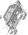
- Fig. 1 is a schematic diagram illustrating an ink jet recording apparatus 11 according to a first embodiment of the present invention.
- the ink jet recording apparatus 11 includes a recording head 13 held in a carriage 12 and ejects ink, an ink supply path 14 for supplying ink to the recording head 13, and an ink tank 15 storing ink.
- the ink jet recording apparatus 11 includes a feeding roller (not illustrated) for feeding a sheet (recording medium), a conveyance roller 16 for conveying the recording medium, and a discharge roller (not illustrated) for discharging the recording medium.
- the ink jet recording apparatus 11 includes an ink suction mechanism 52 for suctioning ink from an ink ejection port 31 ( Fig. 3 ) in the recording head 13 using a tube and a pump while a suction cap is made to abut on the recording head 13 to recover an ejection performance of the recording head 13.
- Fig. 2 is a schematic diagram illustrating an ink supply system of the ink jet recording apparatus 11 according to the present embodiment.
- the ink tank 15 is provided for each corresponding ink color.
- the ink tank 15 includes four ink tanks, i.e., a black ink tank 151, a cyan ink tank 152, a magenta ink tank 153, and a yellow ink tank 154.
- a tube constituting the ink supply path 14 for supplying ink to the recording head 13 is attached to the ink tank 15.
- a tube constituting an air communication path 25 for communicating the inside of the ink tank 15 with an atmosphere is attached to the ink tank 15.
- An ink filling port (ink filling portion) 21 for filling ink is provided on the top of the ink tank 15.
- a tank cap 22 for sealing the ink filling port 21 is attached to the ink filling port 21.
- a user can fill ink into the ink tank 15 from the ink filling port 21 by removing the tank cap 22.
- a valve unit 24, which blocks communication of ink, is provided between the ink tank 15 and the recording head 13 in the ink supply path 14.
- a valve unit 24, which blocks communication of air is provided between the ink tank 15 and an air communication port 23 ( Fig. 3 ) in the air communication path 25.
- the valve unit 24 includes a black-side valve unit and a color-side valve unit.
- the black-side valve unit blocks each of the ink supply path 14 and the air communication path 25 that are connected to the black ink tank 151.
- the color-side valve unit blocks each of the ink supply path 14 and the air communication path 25 that are connected to each of the cyan ink tank 152, the magenta ink tank 153, and the yellow ink tank 154.
- Fig. 3 is a schematic diagram illustrating a positional relationship between the ink tank 15 and the recording head 13.
- a gas-liquid exchange portion 32 in the ink tank 15 is provided at a position lower by a height H in a height direction than the ink ejection port 31 in the recording head 13 to prevent ink from leaking out of the ink ejection port 31 in the recording head 13. More specifically, negative pressure caused by a water head difference corresponding to the height H is applied to the ink ejection port 31.
- a buffer chamber (buffer space) 33 is provided at the bottom of the ink tank 15.
- the buffer chamber 33 can store ink extruded from an ink storage portion 34 when air in the ink storage portion 34 has expanded due to an atmospheric pressure variation and a temperature change. With this configuration, the ink extruded from the ink storage portion 34 can be prevented from leaking out of the ink tank 15 via the air communication path 25.
- a configuration of the ink supply system according to the present embodiment and the flow from filling of ink until a printing operation (recording operation) is enabled will be described below with reference to Figs. 4A, 4B, and 4C to Fig. 6 .
- Figs. 4A, 4B, and 4C are perspective views of the ink jet recording apparatus 11 according to the present embodiment.
- the ink jet recording apparatus 11 includes a scanner unit (reading unit) 41 capable of reading an image on a stocked document.
- the scanner unit 41 is opened, to bring the ink jet recording apparatus 11 into a state illustrated in Fig. 4B .
- Tank covers (first cover members) 42 are provided under the scanner unit 41.
- the tank cover 42 is pivotably supported on the apparatus body, and is movable to a position (first position) where the ink filling port 21 is not exposed and a position (second position) where the ink filling port 21 is exposed.
- the tank cover 42 which covers the ink filling port 21, is moved (opened) to the position where the ink filling port 21 is exposed.
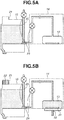
- the tank cover 42 in the present embodiment is also an operation portion in the valve unit 24, details of which will be described below. Accordingly, the valve unit 24 functions interlocking with an operation performed by the user for opening the tank cover 42 so that each of the ink supply path 14 and the air communication path 25 is blocked ( Fig. 5A ).
- the user removes the tank cap 22 attached to the ink filling port 21, and fills ink through the ink filling port 21 from an ink bottle (not illustrated). After the filling of the ink has been completed, the user attaches the tank cap 22 to the ink filling port 21 again, and moves (closes) the tank cover 42 to a position where the ink filling port 21 is not exposed.
- the valve unit 24 functions interlocking with an operation for closing the tank cover 42 so that each of the ink supply path 14 and the air communication path 25 is opened. Then, the user closes the scanner unit 41.
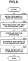
- Fig. 6 is a flowchart of an ink filling sequence executed when the above-described ink suction operation is performed.
- the carriage 12 holding the recording head 13 is moved to a suction position where the ink suction mechanism 52 is provided.
- the suction cap is then made to abut on the recording head 13.
- the ink suction mechanism 52 performs a suction operation for suctioning ink from the ink ejection port 31 in the recording head 13.
- step S64 the suction cap and the recording head 13 are separated from each other after the suction operation has been completed.
- step S65 the carriage 12 is moved from the suction position to a standby position.
- Fig. 7 is a block diagram of the ink jet recording apparatus 11 according to the present embodiment.
- a micro processing unit (MPU) 701 controls an operation of each of the units and processing of data.
- a read-only memory (ROM) 702 stores a program executed by the MPU 701 and data.
- a random access memory (RAM) 703 temporarily stores processing data to be processed by the MPU 701 and data received from a host computer 714.
- a recording head driver 707 controls the recording head 13.
- a carriage motor 704 drives the carriage 12.
- a carriage motor driver 708 controls the carriage motor 704.
- a conveyance motor 705 drives the feeding roller, the conveyance roller 16, and the discharge roller.
- a conveyance motor driver 709 controls the conveyance motor 705.
- a host computer 714 includes a printer driver 7141 for processing recording information such as a recorded image and an image quality and communicating with the ink jet recording apparatus 11 when the user has issued an instruction to perform a recording operation.
- the MPU 701 exchanges the recorded image data with the host computer 714 via an interface (I/F) unit 713.
- FIGs. 8A and 8B are schematic diagrams illustrating the valve unit 24 according to the present embodiment.
- the valve unit 24 holds a tube 81 constituting the ink supply path 14 and the air communication path 25.
- the valve unit 24 includes a holding member 82 for holding the tube 81, and a displacement member 83 which is moved in a Z direction in Figs. 8A and 8B to flatten out the tube 81 and closes the tube 81.
- the valve unit 24 includes a cam member 84 pivotably supported and having a cam surface that is frictionally sliding with the displacement member 83, a cover member 85 supporting the cam member 84 and is fixed to the holding member 82, and a tank cover 42 latched by the cam member 84 and is operated to rotate by the user.
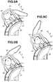
- FIGs. 9A, 9B, and 9C are schematic diagrams illustrating the inside of the valve unit during a closing operation of the valve unit 24 according to the present embodiment.
- Fig. 9A illustrates a state (an opened state) where the displacement member 83 does not flatten out the tube 81.
- the tank cover 42 remains closed ( Fig. 4B ).
- the ink supply path 14 is opened so that ink can be supplied to the recording head 13 from the ink tank 15.
- the air communication path 25 is also opened so that the inside of the ink tank 15 and external air are communicated with each other.
- the cam member 84 rotates in the counterclockwise direction, as illustrated in Fig. 9B .
- Figs. 9B and 9C when a convex portion of the cam member 84 convex with respect to a rotation center of the cam surface of the cam member 84, abuts on the displacement member 83, the displacement member 83 is displaced in a -Z direction in Fig. 9 , to flatten out the tube 81.
- the displacement member 83 rotates to a position illustrated in Fig. 9C , the tube is sufficiently flattened (a closed state).
- the tank cover 42 remains opened ( Fig. 4C ).
- the ink supply path 14 is closed so that ink cannot be supplied to the recording head 13 from the ink tank 15.
- the air communication path 25 is also closed so that the inside of the ink tank 15 and external air are not communicated with each other.
- valves respectively provided in the ink supply path 14 and the air communication path 25 need to be closed when ink is filled into the ink tank 15, as described above.
- a liquid surface of ink in the ink tank 15 may become higher than the height of the ink ejection port 31 ( Fig. 3 ).
- pressure caused by a water head difference corresponding to a height Hm is applied to the ink ejection port 31.
- ink may leak out of the ink ejection port 31, to contaminate the inside of the ink jet recording apparatus 11.
- ink filled in the ink tank 15 may flow into the buffer chamber 33.
- the role of the buffer chamber 33 to store ink extruded from the ink storage portion 34 when there have been an atmospheric pressure variation and a temperature change may be unable to be achieved.
- the ink jet recording apparatus 11 may be configured in such a manner that the liquid surface of ink in the ink tank 15 is always at a position lower than the ink ejection port 31.
- a sufficient amount of ink may be unable to be stored in the ink tank 15 when the height of the ink tank 15 is restricted, and the size of the ink jet recording apparatus 11 may increase when the ink ejection port 31 is provided at a high position.
- the ink jet recording apparatus 11 may also be provided with a sensor capable of detecting that the valve has been closed and provided with a mechanism for automatically opening and closing the valve when the sensor detects that the valve has not been sufficiently closed.
- such a configuration may increase costs.
- the tank cover 42 While the tank cover 42 is closed as illustrated in Fig. 4B , the ink filling port 21 and the tank cap 22 attached to the ink filling port 21 have not been exposed. Accordingly, while the tank cover 42 is closed, the tank cap 22 attached to the ink filling port 21 cannot be detached from the ink filling port 21.
- the tank cover 42 becomes opened as illustrated in Fig. 4C , the tank cap 22 attached to the ink filling port 21 can be detached from the ink filling port 21. More specifically, the tank cover 42 is always opened during ink filling, and the valve can be reliably closed during ink filling.
- Fig. 4A illustrates a state where the scanner unit 41 is closed. In this state, a printing operation can be performed using the recording head 13.
- Figs. 4B and 4C illustrate a state where the scanner unit 41 is opened. In this state, a printing operation cannot be performed.
- the tank cover 42 is opened with the scanner unit 41 thus opened, ink can be filled into the ink tank 15.
- the ink jet recording apparatus 11 includes a sensor (not illustrated) capable of detecting the opening and closing of the scanner unit 41. If it is detected that the scanner unit 41 remains closed, a printing operation can be performed. To close the scanner unit 41, the tank cover 42 first needs to be closed. Accordingly, during the printing operation, the tank cover 42 is always closed, and the valve is opened. This can prevent a situation where no ink is supplied to the recording head 13 because the printing operation is performed with the valve unopened.
- Fig. 10 is a perspective view illustrating a state of the tank cap 22 and the tank cover 42.
- Figs. 11A and 11B are schematic sectional views respectively illustrating a state of the tank cap 22 and the tank cover 42.
- a first tank cap 22a and a third tank cap 22c have been normally mounted on a first ink filling port 21a and a third ink filling port 21c, respectively.
- a second tank cap 22b has not been normally mounted on a second ink filling port 21b, and a gap has made between the second tank cap 22b and the second ink filling port 21b.
- the second tank cap 22b even if an attempt to close the tank cover 42 is made in this state, the second tank cap 22b abuts on a rib 50 provided at the tank cover 42, as illustrated in Fig. 11A . Therefore, the user cannot normally close the tank cover 42.
- the tank cover 42 is prevented (restrained) from moving to a closed position.
- the user can recognize that the second tank cap 22b has not been normally mounted on the second ink filling port 21b.
- the tank cover 42 can be normally closed without the rib 50 and the second tank cap 22b abutting on each other, as illustrated in Fig. 11B .
- a printing operation performed while the tank cap has not been normally mounted on the ink filling port (or does not properly seal a filling portion) can be prevented.
- Figs. 12A and 12B are perspective views of an ink jet recording apparatus 11 according to the present embodiment.
- the ink jet recording apparatus 11 includes an access cover (second cover member) 141. Access to a recording head 13 in the ink jet recording apparatus 11 is enabled by an opening and closing operation of the access cover 141. More specifically, the recording head 13 cannot be accessed with the access cover 141 closed, and can be accessed with the access cover 141 opened.
- Fig. 12A illustrates a state where the access cover 141 is closed. The ink jet recording apparatus 11 can perform a printing operation when the access cover 141 is closed.
- Fig. 12B illustrates a state where the access cover 141 is opened. When tank covers (first cover members) 42 are opened after the access cover 141 has been opened, ink can be filled into the ink tank 15.
- the ink jet recording apparatus 11 includes a sensor (not illustrated) capable of detecting the opening and closing of the access cover 141. If it is detected that the access cover 141 remains closed, a printing operation can be performed. To close the access cover 141, the tank cover 42 needs to be closed. Accordingly, during the printing operation, the tank cover 42 is always closed, and a valve is opened. This can prevent a situation where no ink is supplied to the recording head 13 because the printing operation is performed with the valve unopened.
- the ink jet recording apparatus 11 is configured to open and close the access cover 141 instead of the scanner unit 41 in the first embodiment.
- the present invention is not limited thereto.
- a similar effect can be obtained even in a configuration in which an automatic document feeder (ADF) unit is opened and closed in an ink jet recording apparatus including the ADF unit, and another configuration in which an openable and closable cover member is provided.
- ADF automatic document feeder
- Figs. 13A and 13B are schematic diagrams illustrating an ink supply system according to the present embodiment.
- An ink tank 215 is provided with an air communication port 223, and a gas-liquid separation film 200 is provided to cover the air communication port 223.
- the air-liquid separation film 200 transmits air serving as gas, and does not transmit ink serving as a liquid. More specifically, when ink is ejected by a printing operation, air whose amount corresponds to the amount of consumed ink flows into the ink tank 215 via a gas-liquid exchange portion 232 from the air communication port 223.
- the gas-liquid exchange portion 232 in the ink tank 15 is provided at a position lower by a height H in a height direction than an ink ejection port 31 in a recording head 13. Therefore, negative pressure caused by a water head difference corresponding to the height H is applied to the ink ejection port 31.
- a pressure adjustment portion 201 is provided on the top of the ink tank 215.
- the pressure adjustment portion 201 is rotatably supported around a rotation center 206, and includes an opening/closing lever 203 capable of opening and closing an opening portion 205 and a pressure adjustment spring 202 for pressing the opening/closing lever 203 toward the opening portion 205.
- the pressure adjustment portion 201 is communicated with the external air via an air communication portion 204.
- Fig. 13A illustrates a state when there are a small atmospheric pressure variation and a small temperature change. In this state, the opening/closing lever 203 seals the opening portion 205.
- Fig. 13B illustrates a state where there have been an atmospheric pressure variation and a temperature change.
- the ink tank 215 need not be provided with a buffer chamber so that more ink can be stored in the ink storage portion 234.
- a valve unit 24, which is opened and closed interlocking with a tank cover (first cover member) 42, is provided only in an ink supply path 14 and is not provided in an air communication path 25.
- the air communication port 223 is provided with the gas-liquid separation film 200. Therefore, ink, which has been filled during ink filling, does not leak out via the air communication port 223.
- the air communication port 223 is provided at a position under the ink ejection port 31 in the recording head 13 in the height direction. Therefore, even if a liquid surface of ink has risen to the position of the air communication port 223 due to the atmospheric pressure variation and the temperature change, the recording head 13 is not pressurized. Further, a tube to be closed by the valve unit 24 is only a tube constituting the ink supply path 14. Therefore, a force required when a user operates the tank cover 42 can be reduced.
- a valve can be reliably closed when ink is filled, and the inside of the recording head can be kept at appropriate negative pressure during the printing operation.
- Fig. 14 is a schematic diagram illustrating an ink jet recording apparatus 311 according to the present embodiment.
- access to a recording head 13 in the ink jet recording apparatus 311 is enabled by opening an access cover (first cover member) 341.
- the access cover 341 is used as an operation portion in a valve unit 24 without the tank cover 42 being provided. More specifically, the valve unit 24 is opened and closed interlocking with an opening and closing operation of the access cover 341.
- the access cover 341 is provided with protrusions 301, respectively, at positions opposing a black-side valve unit arranged at the left and a color-side valve unit arranged at the right in Fig. 14 .
- Figs. 15A and 15B are schematic diagrams illustrating inside of a valve unit during a closing operation of the valve unit 24 and illustrating the color-side value unit as viewed from a D direction in Fig. 14 .
- Fig. 15A illustrates a state where the valve is closed.
- An extension spring 310 which is attached to a lever portion 384 formed integrally with a cam member 84, has its one end fixed to an apparatus body. The tension spring 310 pulls the cam member 84 in the counterclockwise direction in Fig. 15A , and rotates the cam member 84 to a position where a tube 81 is closed.
- the protrusion 301 abuts on the lever portion 384, as illustrated in Fig. 15A.
- Fig. 15B illustrates a state where the access cover 341 is closed.
- the lever portion 384 which has been pressed by the protrusion 301, rotates in the clockwise direction in Fig. 15B , and stops at a position where the tube 81 is opened.
- the valve is closed with the access cover 341 opened. Therefore, the valve can be reliably closed during ink filling. On the other hand, the tube 81 can be reliably opened with the access cover 341 closed.
- the ink jet recording apparatus 311 includes a sensor (not illustrated) capable of detecting the opening and closing of the access cover 341, and can perform a printing operation when it is detected that the access cover 341 remains closed. This can prevent a situation where no ink is supplied to the recording head 13 because the printing operation is performed with the valve unopened.
- an ink jet recording apparatus capable of preventing (restraining) a user from erroneously performing an opening and closing operation of a valve in the supply of ink from an ink tank to a recording head.
Landscapes
- Ink Jet (AREA)
Priority Applications (1)
| Application Number | Priority Date | Filing Date | Title |
|---|---|---|---|
| EP19201322.5A EP3623159B1 (en) | 2015-10-30 | 2016-10-28 | Ink jet recording apparatus |
Applications Claiming Priority (1)
| Application Number | Priority Date | Filing Date | Title |
|---|---|---|---|
| JP2015214967A JP6452594B2 (ja) | 2015-10-30 | 2015-10-30 | インクジェット記録装置 |
Related Child Applications (2)
| Application Number | Title | Priority Date | Filing Date |
|---|---|---|---|
| EP19201322.5A Division EP3623159B1 (en) | 2015-10-30 | 2016-10-28 | Ink jet recording apparatus |
| EP19201322.5A Division-Into EP3623159B1 (en) | 2015-10-30 | 2016-10-28 | Ink jet recording apparatus |
Publications (2)
| Publication Number | Publication Date |
|---|---|
| EP3162573A1 EP3162573A1 (en) | 2017-05-03 |
| EP3162573B1 true EP3162573B1 (en) | 2019-12-11 |
Family
ID=57211403
Family Applications (2)
| Application Number | Title | Priority Date | Filing Date |
|---|---|---|---|
| EP16196454.9A Active EP3162573B1 (en) | 2015-10-30 | 2016-10-28 | Ink jet recording apparatus |
| EP19201322.5A Active EP3623159B1 (en) | 2015-10-30 | 2016-10-28 | Ink jet recording apparatus |
Family Applications After (1)
| Application Number | Title | Priority Date | Filing Date |
|---|---|---|---|
| EP19201322.5A Active EP3623159B1 (en) | 2015-10-30 | 2016-10-28 | Ink jet recording apparatus |
Country Status (5)
| Country | Link |
|---|---|
| US (3) | US10131154B2 (https=) |
| EP (2) | EP3162573B1 (https=) |
| JP (1) | JP6452594B2 (https=) |
| KR (1) | KR102098677B1 (https=) |
| CN (2) | CN106626786B (https=) |
Families Citing this family (26)
| Publication number | Priority date | Publication date | Assignee | Title |
|---|---|---|---|---|
| JP6452594B2 (ja) * | 2015-10-30 | 2019-01-16 | キヤノン株式会社 | インクジェット記録装置 |
| JP6794783B2 (ja) * | 2016-11-04 | 2020-12-02 | セイコーエプソン株式会社 | 液体噴射装置 |
| JP2018140549A (ja) * | 2017-02-28 | 2018-09-13 | セイコーエプソン株式会社 | プリンター |
| JP6759127B2 (ja) * | 2017-02-28 | 2020-09-23 | キヤノン株式会社 | インクジェット記録装置 |
| JP2018171739A (ja) | 2017-03-31 | 2018-11-08 | ブラザー工業株式会社 | インクジェット記録装置 |
| WO2019032084A1 (en) * | 2017-08-07 | 2019-02-14 | Hewlett-Packard Development Company, L.P. | PRINTING FLUID RESERVOIR |
| CN109677124B (zh) * | 2017-10-19 | 2021-08-20 | 鸿富锦精密工业(深圳)有限公司 | 墨路开关装置及打印设备 |
| JP7077866B2 (ja) | 2018-08-27 | 2022-05-31 | セイコーエプソン株式会社 | 液体噴射装置 |
| JP7191602B2 (ja) * | 2018-09-10 | 2022-12-19 | キヤノン株式会社 | 液体吐出装置 |
| US11027551B2 (en) | 2019-01-17 | 2021-06-08 | Brother Kogyo Kabushiki Kaisha | System including a reservoir configured to store liquid and a tank to which the reservoir can be connected |
| JP7352127B2 (ja) | 2019-01-17 | 2023-09-28 | ブラザー工業株式会社 | システム |
| JP7259339B2 (ja) | 2019-01-17 | 2023-04-18 | ブラザー工業株式会社 | システム |
| JP7251207B2 (ja) * | 2019-02-25 | 2023-04-04 | セイコーエプソン株式会社 | 液体吐出装置 |
| JP7287049B2 (ja) * | 2019-03-27 | 2023-06-06 | ブラザー工業株式会社 | 液体消費装置 |
| JP7257856B2 (ja) * | 2019-04-05 | 2023-04-14 | キヤノン株式会社 | 記録装置 |
| JP7377003B2 (ja) * | 2019-04-05 | 2023-11-09 | キヤノン株式会社 | 液体吐出装置および制御方法 |
| JP7367355B2 (ja) * | 2019-06-26 | 2023-10-24 | セイコーエプソン株式会社 | 記録装置 |
| JP7528536B2 (ja) * | 2020-05-27 | 2024-08-06 | セイコーエプソン株式会社 | 液体噴射装置 |
| JP7790064B2 (ja) | 2020-09-30 | 2025-12-23 | ブラザー工業株式会社 | 液体吐出装置 |
| JP7665945B2 (ja) * | 2020-09-30 | 2025-04-22 | ブラザー工業株式会社 | 画像記録装置 |
| JP7649157B2 (ja) | 2021-02-12 | 2025-03-19 | キヤノン株式会社 | 液体吐出装置 |
| JP7614873B2 (ja) * | 2021-02-12 | 2025-01-16 | キヤノン株式会社 | 記録装置 |
| JP7592506B2 (ja) * | 2021-02-12 | 2024-12-02 | キヤノン株式会社 | 記録装置、記録装置の制御方法、液体移送装置、および液体移送装置の制御方法 |
| JP7749964B2 (ja) * | 2021-07-26 | 2025-10-07 | ブラザー工業株式会社 | 液体吐出装置及び液体貯留器 |
| JP2023079044A (ja) * | 2021-11-26 | 2023-06-07 | キヤノン株式会社 | 液体吐出装置 |
| JP7831123B2 (ja) * | 2022-05-02 | 2026-03-17 | セイコーエプソン株式会社 | 液体噴射装置 |
Family Cites Families (23)
| Publication number | Priority date | Publication date | Assignee | Title |
|---|---|---|---|---|
| JP3374209B2 (ja) * | 1994-11-18 | 2003-02-04 | セイコーエプソン株式会社 | インクジェットプリンタ用インク供給装置 |
| JP2000094706A (ja) * | 1998-09-17 | 2000-04-04 | Canon Inc | インクジェット記録装置 |
| JP2001010078A (ja) * | 1999-04-27 | 2001-01-16 | Canon Inc | インクタンク、該インクタンクが取り付けられるホルダー、該ホルダーを備えたインクジェット記録装置、インクタンクのホルダーへの装着方法 |
| JP4524860B2 (ja) * | 2000-05-30 | 2010-08-18 | 船井電機株式会社 | インクジェット装置 |
| JP2002301848A (ja) * | 2001-04-04 | 2002-10-15 | Funai Electric Co Ltd | インクジェット式プリンタ |
| JP4513337B2 (ja) * | 2004-01-23 | 2010-07-28 | セイコーエプソン株式会社 | インクカートリッジ |
| JP2007021971A (ja) * | 2005-07-20 | 2007-02-01 | Seiko Epson Corp | 液体噴射装置 |
| JP2007106019A (ja) * | 2005-10-14 | 2007-04-26 | Seiko Epson Corp | インクジェット記録装置 |
| JP4579813B2 (ja) * | 2005-11-24 | 2010-11-10 | キヤノン株式会社 | 液体噴射記録装置 |
| JP4605394B2 (ja) * | 2006-03-31 | 2011-01-05 | ブラザー工業株式会社 | インクカートリッジの収納装置に対する保護装置 |
| JP2008173871A (ja) * | 2007-01-19 | 2008-07-31 | Seiko Epson Corp | 流体供給装置およびそれを用いた流体噴射装置 |
| KR20080069388A (ko) * | 2007-01-23 | 2008-07-28 | 삼성전자주식회사 | 잉크 공급/차단장치 및 화상형성장치 |
| JP2008265350A (ja) * | 2008-06-27 | 2008-11-06 | Seiko Epson Corp | インクジェットプリンタ |
| JP5163344B2 (ja) | 2008-07-30 | 2013-03-13 | セイコーエプソン株式会社 | 液滴吐出装置および液滴吐出装置のヘッドクリーニング制御方法 |
| JP6083167B2 (ja) * | 2012-09-14 | 2017-02-22 | セイコーエプソン株式会社 | 液体収容体及び液体消費装置 |
| JP6020804B2 (ja) * | 2012-08-10 | 2016-11-02 | セイコーエプソン株式会社 | 記録装置 |
| TWI483853B (zh) | 2012-09-21 | 2015-05-11 | Cal Comp Electronics & Comm Co | 多功能事務機 |
| TWI504520B (zh) * | 2012-12-20 | 2015-10-21 | Cal Comp Electronics & Comm Co | 供墨系統與媒體記錄裝置 |
| US9090081B2 (en) * | 2012-09-21 | 2015-07-28 | Cal-Comp Electronics & Communications Company Limited | Ink supply system and multifunctional printer |
| JP2014079910A (ja) | 2012-10-15 | 2014-05-08 | Seiko Epson Corp | 記録装置 |
| JP2014100842A (ja) * | 2012-11-19 | 2014-06-05 | Ricoh Co Ltd | 画像形成装置 |
| JP2015112847A (ja) * | 2013-12-13 | 2015-06-22 | 株式会社リコー | 液体供給装置及びこれを備えた画像形成装置 |
| JP6452594B2 (ja) * | 2015-10-30 | 2019-01-16 | キヤノン株式会社 | インクジェット記録装置 |
-
2015
- 2015-10-30 JP JP2015214967A patent/JP6452594B2/ja active Active
-
2016
- 2016-10-25 CN CN201610922678.4A patent/CN106626786B/zh active Active
- 2016-10-25 CN CN201811155205.1A patent/CN109130521B/zh active Active
- 2016-10-26 US US15/335,277 patent/US10131154B2/en active Active
- 2016-10-28 KR KR1020160141567A patent/KR102098677B1/ko active Active
- 2016-10-28 EP EP16196454.9A patent/EP3162573B1/en active Active
- 2016-10-28 EP EP19201322.5A patent/EP3623159B1/en active Active
-
2018
- 2018-10-09 US US16/155,611 patent/US10625514B2/en not_active Ceased
-
2022
- 2022-04-20 US US17/725,082 patent/USRE50645E1/en active Active
Non-Patent Citations (1)
| Title |
|---|
| None * |
Also Published As
| Publication number | Publication date |
|---|---|
| CN109130521A (zh) | 2019-01-04 |
| CN109130521B (zh) | 2020-08-11 |
| JP6452594B2 (ja) | 2019-01-16 |
| EP3623159B1 (en) | 2024-07-10 |
| KR102098677B1 (ko) | 2020-04-08 |
| KR20170051317A (ko) | 2017-05-11 |
| EP3623159A1 (en) | 2020-03-18 |
| US10131154B2 (en) | 2018-11-20 |
| US20190039383A1 (en) | 2019-02-07 |
| USRE50645E1 (en) | 2025-10-21 |
| JP2017081121A (ja) | 2017-05-18 |
| CN106626786A (zh) | 2017-05-10 |
| CN106626786B (zh) | 2018-11-09 |
| US10625514B2 (en) | 2020-04-21 |
| US20170120617A1 (en) | 2017-05-04 |
| EP3162573A1 (en) | 2017-05-03 |
Similar Documents
| Publication | Publication Date | Title |
|---|---|---|
| USRE50645E1 (en) | Ink jet recording apparatus | |
| JP6667260B2 (ja) | インクジェット記録装置 | |
| US8186815B2 (en) | Liquid ejection device and sub tank for use with the same | |
| US11975545B2 (en) | Liquid consumption device | |
| US20220258487A1 (en) | Printing apparatus | |
| JP2009039927A (ja) | 液滴吐出装置 | |
| JP6605115B2 (ja) | インクジェット記録装置 | |
| US20220063277A1 (en) | Recording apparatus | |
| JP2020051600A (ja) | 流路制御装置およびインクジェット記録装置 | |
| JP7191602B2 (ja) | 液体吐出装置 | |
| JP7102165B2 (ja) | インクジェット記録装置、その制御方法、およびプログラム | |
| US11584128B2 (en) | Printhead priming and venting | |
| JP2017081125A (ja) | インクジェット記録装置 | |
| JP2021194900A (ja) | 液体吐出装置 |
Legal Events
| Date | Code | Title | Description |
|---|---|---|---|
| PUAI | Public reference made under article 153(3) epc to a published international application that has entered the european phase |
Free format text: ORIGINAL CODE: 0009012 |
|
| STAA | Information on the status of an ep patent application or granted ep patent |
Free format text: STATUS: THE APPLICATION HAS BEEN PUBLISHED |
|
| AK | Designated contracting states |
Kind code of ref document: A1 Designated state(s): AL AT BE BG CH CY CZ DE DK EE ES FI FR GB GR HR HU IE IS IT LI LT LU LV MC MK MT NL NO PL PT RO RS SE SI SK SM TR |
|
| AX | Request for extension of the european patent |
Extension state: BA ME |
|
| STAA | Information on the status of an ep patent application or granted ep patent |
Free format text: STATUS: REQUEST FOR EXAMINATION WAS MADE |
|
| 17P | Request for examination filed |
Effective date: 20171103 |
|
| RBV | Designated contracting states (corrected) |
Designated state(s): AL AT BE BG CH CY CZ DE DK EE ES FI FR GB GR HR HU IE IS IT LI LT LU LV MC MK MT NL NO PL PT RO RS SE SI SK SM TR |
|
| GRAP | Despatch of communication of intention to grant a patent |
Free format text: ORIGINAL CODE: EPIDOSNIGR1 |
|
| STAA | Information on the status of an ep patent application or granted ep patent |
Free format text: STATUS: GRANT OF PATENT IS INTENDED |
|
| INTG | Intention to grant announced |
Effective date: 20190605 |
|
| GRAS | Grant fee paid |
Free format text: ORIGINAL CODE: EPIDOSNIGR3 |
|
| GRAA | (expected) grant |
Free format text: ORIGINAL CODE: 0009210 |
|
| STAA | Information on the status of an ep patent application or granted ep patent |
Free format text: STATUS: THE PATENT HAS BEEN GRANTED |
|
| AK | Designated contracting states |
Kind code of ref document: B1 Designated state(s): AL AT BE BG CH CY CZ DE DK EE ES FI FR GB GR HR HU IE IS IT LI LT LU LV MC MK MT NL NO PL PT RO RS SE SI SK SM TR |
|
| REG | Reference to a national code |
Ref country code: GB Ref legal event code: FG4D |
|
| REG | Reference to a national code |
Ref country code: CH Ref legal event code: EP |
|
| REG | Reference to a national code |
Ref country code: AT Ref legal event code: REF Ref document number: 1211798 Country of ref document: AT Kind code of ref document: T Effective date: 20191215 |
|
| REG | Reference to a national code |
Ref country code: DE Ref legal event code: R096 Ref document number: 602016025934 Country of ref document: DE |
|
| REG | Reference to a national code |
Ref country code: IE Ref legal event code: FG4D |
|
| REG | Reference to a national code |
Ref country code: NL Ref legal event code: MP Effective date: 20191211 |
|
| REG | Reference to a national code |
Ref country code: LT Ref legal event code: MG4D |
|
| PG25 | Lapsed in a contracting state [announced via postgrant information from national office to epo] |
Ref country code: LT Free format text: LAPSE BECAUSE OF FAILURE TO SUBMIT A TRANSLATION OF THE DESCRIPTION OR TO PAY THE FEE WITHIN THE PRESCRIBED TIME-LIMIT Effective date: 20191211 Ref country code: NO Free format text: LAPSE BECAUSE OF FAILURE TO SUBMIT A TRANSLATION OF THE DESCRIPTION OR TO PAY THE FEE WITHIN THE PRESCRIBED TIME-LIMIT Effective date: 20200311 Ref country code: GR Free format text: LAPSE BECAUSE OF FAILURE TO SUBMIT A TRANSLATION OF THE DESCRIPTION OR TO PAY THE FEE WITHIN THE PRESCRIBED TIME-LIMIT Effective date: 20200312 Ref country code: FI Free format text: LAPSE BECAUSE OF FAILURE TO SUBMIT A TRANSLATION OF THE DESCRIPTION OR TO PAY THE FEE WITHIN THE PRESCRIBED TIME-LIMIT Effective date: 20191211 Ref country code: LV Free format text: LAPSE BECAUSE OF FAILURE TO SUBMIT A TRANSLATION OF THE DESCRIPTION OR TO PAY THE FEE WITHIN THE PRESCRIBED TIME-LIMIT Effective date: 20191211 Ref country code: BG Free format text: LAPSE BECAUSE OF FAILURE TO SUBMIT A TRANSLATION OF THE DESCRIPTION OR TO PAY THE FEE WITHIN THE PRESCRIBED TIME-LIMIT Effective date: 20200311 Ref country code: SE Free format text: LAPSE BECAUSE OF FAILURE TO SUBMIT A TRANSLATION OF THE DESCRIPTION OR TO PAY THE FEE WITHIN THE PRESCRIBED TIME-LIMIT Effective date: 20191211 |
|
| PG25 | Lapsed in a contracting state [announced via postgrant information from national office to epo] |
Ref country code: HR Free format text: LAPSE BECAUSE OF FAILURE TO SUBMIT A TRANSLATION OF THE DESCRIPTION OR TO PAY THE FEE WITHIN THE PRESCRIBED TIME-LIMIT Effective date: 20191211 Ref country code: RS Free format text: LAPSE BECAUSE OF FAILURE TO SUBMIT A TRANSLATION OF THE DESCRIPTION OR TO PAY THE FEE WITHIN THE PRESCRIBED TIME-LIMIT Effective date: 20191211 |
|
| PG25 | Lapsed in a contracting state [announced via postgrant information from national office to epo] |
Ref country code: AL Free format text: LAPSE BECAUSE OF FAILURE TO SUBMIT A TRANSLATION OF THE DESCRIPTION OR TO PAY THE FEE WITHIN THE PRESCRIBED TIME-LIMIT Effective date: 20191211 |
|
| PG25 | Lapsed in a contracting state [announced via postgrant information from national office to epo] |
Ref country code: ES Free format text: LAPSE BECAUSE OF FAILURE TO SUBMIT A TRANSLATION OF THE DESCRIPTION OR TO PAY THE FEE WITHIN THE PRESCRIBED TIME-LIMIT Effective date: 20191211 Ref country code: RO Free format text: LAPSE BECAUSE OF FAILURE TO SUBMIT A TRANSLATION OF THE DESCRIPTION OR TO PAY THE FEE WITHIN THE PRESCRIBED TIME-LIMIT Effective date: 20191211 Ref country code: CZ Free format text: LAPSE BECAUSE OF FAILURE TO SUBMIT A TRANSLATION OF THE DESCRIPTION OR TO PAY THE FEE WITHIN THE PRESCRIBED TIME-LIMIT Effective date: 20191211 Ref country code: NL Free format text: LAPSE BECAUSE OF FAILURE TO SUBMIT A TRANSLATION OF THE DESCRIPTION OR TO PAY THE FEE WITHIN THE PRESCRIBED TIME-LIMIT Effective date: 20191211 Ref country code: PT Free format text: LAPSE BECAUSE OF FAILURE TO SUBMIT A TRANSLATION OF THE DESCRIPTION OR TO PAY THE FEE WITHIN THE PRESCRIBED TIME-LIMIT Effective date: 20200506 Ref country code: EE Free format text: LAPSE BECAUSE OF FAILURE TO SUBMIT A TRANSLATION OF THE DESCRIPTION OR TO PAY THE FEE WITHIN THE PRESCRIBED TIME-LIMIT Effective date: 20191211 |
|
| PG25 | Lapsed in a contracting state [announced via postgrant information from national office to epo] |
Ref country code: SM Free format text: LAPSE BECAUSE OF FAILURE TO SUBMIT A TRANSLATION OF THE DESCRIPTION OR TO PAY THE FEE WITHIN THE PRESCRIBED TIME-LIMIT Effective date: 20191211 Ref country code: SK Free format text: LAPSE BECAUSE OF FAILURE TO SUBMIT A TRANSLATION OF THE DESCRIPTION OR TO PAY THE FEE WITHIN THE PRESCRIBED TIME-LIMIT Effective date: 20191211 Ref country code: IS Free format text: LAPSE BECAUSE OF FAILURE TO SUBMIT A TRANSLATION OF THE DESCRIPTION OR TO PAY THE FEE WITHIN THE PRESCRIBED TIME-LIMIT Effective date: 20200411 |
|
| REG | Reference to a national code |
Ref country code: DE Ref legal event code: R097 Ref document number: 602016025934 Country of ref document: DE |
|
| REG | Reference to a national code |
Ref country code: AT Ref legal event code: MK05 Ref document number: 1211798 Country of ref document: AT Kind code of ref document: T Effective date: 20191211 |
|
| PLBE | No opposition filed within time limit |
Free format text: ORIGINAL CODE: 0009261 |
|
| STAA | Information on the status of an ep patent application or granted ep patent |
Free format text: STATUS: NO OPPOSITION FILED WITHIN TIME LIMIT |
|
| PG25 | Lapsed in a contracting state [announced via postgrant information from national office to epo] |
Ref country code: DK Free format text: LAPSE BECAUSE OF FAILURE TO SUBMIT A TRANSLATION OF THE DESCRIPTION OR TO PAY THE FEE WITHIN THE PRESCRIBED TIME-LIMIT Effective date: 20191211 |
|
| 26N | No opposition filed |
Effective date: 20200914 |
|
| PG25 | Lapsed in a contracting state [announced via postgrant information from national office to epo] |
Ref country code: AT Free format text: LAPSE BECAUSE OF FAILURE TO SUBMIT A TRANSLATION OF THE DESCRIPTION OR TO PAY THE FEE WITHIN THE PRESCRIBED TIME-LIMIT Effective date: 20191211 Ref country code: SI Free format text: LAPSE BECAUSE OF FAILURE TO SUBMIT A TRANSLATION OF THE DESCRIPTION OR TO PAY THE FEE WITHIN THE PRESCRIBED TIME-LIMIT Effective date: 20191211 |
|
| PG25 | Lapsed in a contracting state [announced via postgrant information from national office to epo] |
Ref country code: IT Free format text: LAPSE BECAUSE OF FAILURE TO SUBMIT A TRANSLATION OF THE DESCRIPTION OR TO PAY THE FEE WITHIN THE PRESCRIBED TIME-LIMIT Effective date: 20191211 |
|
| PG25 | Lapsed in a contracting state [announced via postgrant information from national office to epo] |
Ref country code: PL Free format text: LAPSE BECAUSE OF FAILURE TO SUBMIT A TRANSLATION OF THE DESCRIPTION OR TO PAY THE FEE WITHIN THE PRESCRIBED TIME-LIMIT Effective date: 20191211 |
|
| REG | Reference to a national code |
Ref country code: CH Ref legal event code: PL |
|
| PG25 | Lapsed in a contracting state [announced via postgrant information from national office to epo] |
Ref country code: MC Free format text: LAPSE BECAUSE OF FAILURE TO SUBMIT A TRANSLATION OF THE DESCRIPTION OR TO PAY THE FEE WITHIN THE PRESCRIBED TIME-LIMIT Effective date: 20191211 Ref country code: LU Free format text: LAPSE BECAUSE OF NON-PAYMENT OF DUE FEES Effective date: 20201028 |
|
| REG | Reference to a national code |
Ref country code: BE Ref legal event code: MM Effective date: 20201031 |
|
| PG25 | Lapsed in a contracting state [announced via postgrant information from national office to epo] |
Ref country code: FR Free format text: LAPSE BECAUSE OF NON-PAYMENT OF DUE FEES Effective date: 20201031 |
|
| PG25 | Lapsed in a contracting state [announced via postgrant information from national office to epo] |
Ref country code: LI Free format text: LAPSE BECAUSE OF NON-PAYMENT OF DUE FEES Effective date: 20201031 Ref country code: CH Free format text: LAPSE BECAUSE OF NON-PAYMENT OF DUE FEES Effective date: 20201031 Ref country code: BE Free format text: LAPSE BECAUSE OF NON-PAYMENT OF DUE FEES Effective date: 20201031 |
|
| PG25 | Lapsed in a contracting state [announced via postgrant information from national office to epo] |
Ref country code: IE Free format text: LAPSE BECAUSE OF NON-PAYMENT OF DUE FEES Effective date: 20201028 |
|
| PG25 | Lapsed in a contracting state [announced via postgrant information from national office to epo] |
Ref country code: TR Free format text: LAPSE BECAUSE OF FAILURE TO SUBMIT A TRANSLATION OF THE DESCRIPTION OR TO PAY THE FEE WITHIN THE PRESCRIBED TIME-LIMIT Effective date: 20191211 Ref country code: MT Free format text: LAPSE BECAUSE OF FAILURE TO SUBMIT A TRANSLATION OF THE DESCRIPTION OR TO PAY THE FEE WITHIN THE PRESCRIBED TIME-LIMIT Effective date: 20191211 Ref country code: CY Free format text: LAPSE BECAUSE OF FAILURE TO SUBMIT A TRANSLATION OF THE DESCRIPTION OR TO PAY THE FEE WITHIN THE PRESCRIBED TIME-LIMIT Effective date: 20191211 |
|
| PG25 | Lapsed in a contracting state [announced via postgrant information from national office to epo] |
Ref country code: MK Free format text: LAPSE BECAUSE OF FAILURE TO SUBMIT A TRANSLATION OF THE DESCRIPTION OR TO PAY THE FEE WITHIN THE PRESCRIBED TIME-LIMIT Effective date: 20191211 |
|
| PGFP | Annual fee paid to national office [announced via postgrant information from national office to epo] |
Ref country code: GB Payment date: 20250923 Year of fee payment: 10 |
|
| PGFP | Annual fee paid to national office [announced via postgrant information from national office to epo] |
Ref country code: DE Payment date: 20250923 Year of fee payment: 10 |