EP3152142B1 - Druckvorrichtung, entsprechendes drucksystem, und verfahren zum betrieb einer druckvorrichtung - Google Patents
Druckvorrichtung, entsprechendes drucksystem, und verfahren zum betrieb einer druckvorrichtung Download PDFInfo
- Publication number
- EP3152142B1 EP3152142B1 EP14733107.8A EP14733107A EP3152142B1 EP 3152142 B1 EP3152142 B1 EP 3152142B1 EP 14733107 A EP14733107 A EP 14733107A EP 3152142 B1 EP3152142 B1 EP 3152142B1
- Authority
- EP
- European Patent Office
- Prior art keywords
- media
- substrate
- printing device
- guide
- accessory
- Prior art date
- Legal status (The legal status is an assumption and is not a legal conclusion. Google has not performed a legal analysis and makes no representation as to the accuracy of the status listed.)
- Active
Links
Images


Classifications
-
- B—PERFORMING OPERATIONS; TRANSPORTING
- B65—CONVEYING; PACKING; STORING; HANDLING THIN OR FILAMENTARY MATERIAL
- B65H—HANDLING THIN OR FILAMENTARY MATERIAL, e.g. SHEETS, WEBS, CABLES
- B65H5/00—Feeding articles separated from piles; Feeding articles to machines
- B65H5/36—Article guides or smoothers, e.g. movable in operation
-
- B—PERFORMING OPERATIONS; TRANSPORTING
- B65—CONVEYING; PACKING; STORING; HANDLING THIN OR FILAMENTARY MATERIAL
- B65H—HANDLING THIN OR FILAMENTARY MATERIAL, e.g. SHEETS, WEBS, CABLES
- B65H20/00—Advancing webs
- B65H20/30—Arrangements for accumulating surplus web
- B65H20/32—Arrangements for accumulating surplus web by making loops
-
- B—PERFORMING OPERATIONS; TRANSPORTING
- B65—CONVEYING; PACKING; STORING; HANDLING THIN OR FILAMENTARY MATERIAL
- B65H—HANDLING THIN OR FILAMENTARY MATERIAL, e.g. SHEETS, WEBS, CABLES
- B65H29/00—Delivering or advancing articles from machines; Advancing articles to or into piles
- B65H29/52—Stationary guides or smoothers
-
- B—PERFORMING OPERATIONS; TRANSPORTING
- B65—CONVEYING; PACKING; STORING; HANDLING THIN OR FILAMENTARY MATERIAL
- B65H—HANDLING THIN OR FILAMENTARY MATERIAL, e.g. SHEETS, WEBS, CABLES
- B65H29/00—Delivering or advancing articles from machines; Advancing articles to or into piles
- B65H29/58—Article switches or diverters
- B65H29/60—Article switches or diverters diverting the stream into alternative paths
-
- B—PERFORMING OPERATIONS; TRANSPORTING
- B65—CONVEYING; PACKING; STORING; HANDLING THIN OR FILAMENTARY MATERIAL
- B65H—HANDLING THIN OR FILAMENTARY MATERIAL, e.g. SHEETS, WEBS, CABLES
- B65H7/00—Controlling article feeding, separating, pile-advancing, or associated apparatus, to take account of incorrect feeding, absence of articles, or presence of faulty articles
- B65H7/02—Controlling article feeding, separating, pile-advancing, or associated apparatus, to take account of incorrect feeding, absence of articles, or presence of faulty articles by feelers or detectors
-
- G—PHYSICS
- G03—PHOTOGRAPHY; CINEMATOGRAPHY; ANALOGOUS TECHNIQUES USING WAVES OTHER THAN OPTICAL WAVES; ELECTROGRAPHY; HOLOGRAPHY
- G03G—ELECTROGRAPHY; ELECTROPHOTOGRAPHY; MAGNETOGRAPHY
- G03G15/00—Apparatus for electrographic processes using a charge pattern
- G03G15/65—Apparatus which relate to the handling of copy material
- G03G15/6555—Handling of sheet copy material taking place in a specific part of the copy material feeding path
- G03G15/6558—Feeding path after the copy sheet preparation and up to the transfer point, e.g. registering; Deskewing; Correct timing of sheet feeding to the transfer point
-
- B—PERFORMING OPERATIONS; TRANSPORTING
- B65—CONVEYING; PACKING; STORING; HANDLING THIN OR FILAMENTARY MATERIAL
- B65H—HANDLING THIN OR FILAMENTARY MATERIAL, e.g. SHEETS, WEBS, CABLES
- B65H2301/00—Handling processes for sheets or webs
- B65H2301/50—Auxiliary process performed during handling process
- B65H2301/51—Modifying a characteristic of handled material
- B65H2301/512—Changing form of handled material
- B65H2301/5121—Bending, buckling, curling, bringing a curvature
- B65H2301/51212—Bending, buckling, curling, bringing a curvature perpendicularly to the direction of displacement of handled material, e.g. forming a loop
-
- B—PERFORMING OPERATIONS; TRANSPORTING
- B65—CONVEYING; PACKING; STORING; HANDLING THIN OR FILAMENTARY MATERIAL
- B65H—HANDLING THIN OR FILAMENTARY MATERIAL, e.g. SHEETS, WEBS, CABLES
- B65H2402/00—Constructional details of the handling apparatus
- B65H2402/10—Modular constructions, e.g. using preformed elements or profiles
-
- B—PERFORMING OPERATIONS; TRANSPORTING
- B65—CONVEYING; PACKING; STORING; HANDLING THIN OR FILAMENTARY MATERIAL
- B65H—HANDLING THIN OR FILAMENTARY MATERIAL, e.g. SHEETS, WEBS, CABLES
- B65H2404/00—Parts for transporting or guiding the handled material
- B65H2404/60—Other elements in face contact with handled material
- B65H2404/63—Oscillating, pivoting around an axis parallel to face of material, e.g. diverting means
- B65H2404/632—Wedge member
-
- B—PERFORMING OPERATIONS; TRANSPORTING
- B65—CONVEYING; PACKING; STORING; HANDLING THIN OR FILAMENTARY MATERIAL
- B65H—HANDLING THIN OR FILAMENTARY MATERIAL, e.g. SHEETS, WEBS, CABLES
- B65H2404/00—Parts for transporting or guiding the handled material
- B65H2404/60—Other elements in face contact with handled material
- B65H2404/69—Other means designated for special purpose
- B65H2404/693—Retractable guiding means, i.e. between guiding and non guiding position
-
- B—PERFORMING OPERATIONS; TRANSPORTING
- B65—CONVEYING; PACKING; STORING; HANDLING THIN OR FILAMENTARY MATERIAL
- B65H—HANDLING THIN OR FILAMENTARY MATERIAL, e.g. SHEETS, WEBS, CABLES
- B65H2404/00—Parts for transporting or guiding the handled material
- B65H2404/70—Other elements in edge contact with handled material, e.g. registering, orientating, guiding devices
- B65H2404/74—Guiding means
- B65H2404/741—Guiding means movable in operation
- B65H2404/7414—Guiding means movable in operation pivotable
-
- B—PERFORMING OPERATIONS; TRANSPORTING
- B65—CONVEYING; PACKING; STORING; HANDLING THIN OR FILAMENTARY MATERIAL
- B65H—HANDLING THIN OR FILAMENTARY MATERIAL, e.g. SHEETS, WEBS, CABLES
- B65H2511/00—Dimensions; Position; Numbers; Identification; Occurrences
- B65H2511/10—Size; Dimensions
- B65H2511/11—Length
- B65H2511/112—Length of a loop, e.g. a free loop or a loop of dancer rollers
-
- B—PERFORMING OPERATIONS; TRANSPORTING
- B65—CONVEYING; PACKING; STORING; HANDLING THIN OR FILAMENTARY MATERIAL
- B65H—HANDLING THIN OR FILAMENTARY MATERIAL, e.g. SHEETS, WEBS, CABLES
- B65H2511/00—Dimensions; Position; Numbers; Identification; Occurrences
- B65H2511/20—Location in space
- B65H2511/21—Angle
- B65H2511/214—Inclination
-
- B—PERFORMING OPERATIONS; TRANSPORTING
- B65—CONVEYING; PACKING; STORING; HANDLING THIN OR FILAMENTARY MATERIAL
- B65H—HANDLING THIN OR FILAMENTARY MATERIAL, e.g. SHEETS, WEBS, CABLES
- B65H2511/00—Dimensions; Position; Numbers; Identification; Occurrences
- B65H2511/50—Occurence
- B65H2511/51—Presence
-
- B—PERFORMING OPERATIONS; TRANSPORTING
- B65—CONVEYING; PACKING; STORING; HANDLING THIN OR FILAMENTARY MATERIAL
- B65H—HANDLING THIN OR FILAMENTARY MATERIAL, e.g. SHEETS, WEBS, CABLES
- B65H2513/00—Dynamic entities; Timing aspects
- B65H2513/10—Speed
-
- B—PERFORMING OPERATIONS; TRANSPORTING
- B65—CONVEYING; PACKING; STORING; HANDLING THIN OR FILAMENTARY MATERIAL
- B65H—HANDLING THIN OR FILAMENTARY MATERIAL, e.g. SHEETS, WEBS, CABLES
- B65H2515/00—Physical entities not provided for in groups B65H2511/00 or B65H2513/00
- B65H2515/81—Rigidity; Stiffness; Elasticity
-
- B—PERFORMING OPERATIONS; TRANSPORTING
- B65—CONVEYING; PACKING; STORING; HANDLING THIN OR FILAMENTARY MATERIAL
- B65H—HANDLING THIN OR FILAMENTARY MATERIAL, e.g. SHEETS, WEBS, CABLES
- B65H2553/00—Sensing or detecting means
- B65H2553/80—Arangement of the sensing means
- B65H2553/81—Arangement of the sensing means on a movable element
-
- B—PERFORMING OPERATIONS; TRANSPORTING
- B65—CONVEYING; PACKING; STORING; HANDLING THIN OR FILAMENTARY MATERIAL
- B65H—HANDLING THIN OR FILAMENTARY MATERIAL, e.g. SHEETS, WEBS, CABLES
- B65H2801/00—Application field
- B65H2801/03—Image reproduction devices
- B65H2801/06—Office-type machines, e.g. photocopiers
-
- B—PERFORMING OPERATIONS; TRANSPORTING
- B65—CONVEYING; PACKING; STORING; HANDLING THIN OR FILAMENTARY MATERIAL
- B65H—HANDLING THIN OR FILAMENTARY MATERIAL, e.g. SHEETS, WEBS, CABLES
- B65H2801/00—Application field
- B65H2801/03—Image reproduction devices
- B65H2801/21—Industrial-size printers, e.g. rotary printing press
-
- G—PHYSICS
- G03—PHOTOGRAPHY; CINEMATOGRAPHY; ANALOGOUS TECHNIQUES USING WAVES OTHER THAN OPTICAL WAVES; ELECTROGRAPHY; HOLOGRAPHY
- G03G—ELECTROGRAPHY; ELECTROPHOTOGRAPHY; MAGNETOGRAPHY
- G03G15/00—Apparatus for electrographic processes using a charge pattern
- G03G15/14—Apparatus for electrographic processes using a charge pattern for transferring a pattern to a second base
- G03G15/16—Apparatus for electrographic processes using a charge pattern for transferring a pattern to a second base of a toner pattern, e.g. a powder pattern, e.g. magnetic transfer
- G03G15/1695—Apparatus for electrographic processes using a charge pattern for transferring a pattern to a second base of a toner pattern, e.g. a powder pattern, e.g. magnetic transfer with means for preconditioning the paper base before the transfer
-
- G—PHYSICS
- G03—PHOTOGRAPHY; CINEMATOGRAPHY; ANALOGOUS TECHNIQUES USING WAVES OTHER THAN OPTICAL WAVES; ELECTROGRAPHY; HOLOGRAPHY
- G03G—ELECTROGRAPHY; ELECTROPHOTOGRAPHY; MAGNETOGRAPHY
- G03G2215/00—Apparatus for electrophotographic processes
- G03G2215/00362—Apparatus for electrophotographic processes relating to the copy medium handling
- G03G2215/00535—Stable handling of copy medium
- G03G2215/00679—Conveying means details, e.g. roller
-
- G—PHYSICS
- G03—PHOTOGRAPHY; CINEMATOGRAPHY; ANALOGOUS TECHNIQUES USING WAVES OTHER THAN OPTICAL WAVES; ELECTROGRAPHY; HOLOGRAPHY
- G03G—ELECTROGRAPHY; ELECTROPHOTOGRAPHY; MAGNETOGRAPHY
- G03G2215/00—Apparatus for electrophotographic processes
- G03G2215/00362—Apparatus for electrophotographic processes relating to the copy medium handling
- G03G2215/00789—Adding properties or qualities to the copy medium
- G03G2215/00801—Coating device
Definitions
- a substrate may be fed from the printing device to an accessory device, see e.g. US 2010/0066009 A1 , or the substrate may be received by the printing device from an accessory device, see e.g. US 5,326,093 A .
- a printing device may form an image on a substrate and then feed the substrate to an accessory device for stacking, binding, stapling or any other finishing operation. Pre-printing operations, such as priming of the substrate may be performed prior to the substrate being received by the printing device.
- JP H06 191686 A discloses a sheet feeding apparatus for correcting inclination of a sheet, by providing a guide member which is pivoted in response to the leading edge of the sheet abutting against a register roller.
- US 2005/0156373 A1 discloses a printing device wherein a sensor is disposed on a movable media guide.
- JP H05 50318 U discloses a printing device comprising a movable sensor to provide a signal indicative of the detected extent by which a substrate forms a loop in a buffer region.
- Figures 1a and 1b schematically illustrate the components of a printing system 100, which is an exemplary system used to illustrate the features of the present application.
- Figures 1a and 1b are schematic diagrams and as such certain components have been omitted to facilitate a description of the example. Actual implementations may vary in practice.
- the printing system 100 includes a printing device (referred to hereinafter as a printer) 102 and an external accessory device 104.
- the printer 102 is arranged to print a desired image 105 onto a printable media substrate 106 (referred to herein as the substrate), as the substrate 106 is transported through the printer 102 in a downstream direction 107.
- the accessory device 104 may be a downstream accessory device as shown in Figure 1a . Such a downstream accessory device may perform one or more functions after the printer 102 has printed to the substrate 106. For example, the accessory device 104 may perform functions including one or more of: coating, varnishing, foil stamping, texturing, lamination, cutting, creasing, folding, gluing, stacking, binding, stapling, splicing, rewinding, or any other suitable function.
- the accessory device 104 may be a multifunction finisher arranged to do more than one of these functions.
- the printer 102 is an inkjet printer.
- the printer 102 includes one or more printing elements.
- Each printing element may include one or more print bars or one or more print heads.
- the printer 102 uses a print bar 108 which laterally extends across a printable width of the substrate 106, to print a desired image 105 onto the substrate 106. This is shown more clearly in Figure 1b .
- This type of printer 102 is sometimes referred to as a 'page-wide' array printer.
- the printer 102 includes a single print bar 108. However, it will be understood that the example could equally be applied to a plurality of static print bars or one or more moveably-mounted print bars and/or print heads.
- the print bar 108 comprises a plurality of nozzles that are arranged to eject liquid ink onto the substrate 106.
- the desired image 105 is communicated to the printer 102 in digital form.
- the desired image 105 may include any combination of text, graphics and images.
- each printing element may have a print element controller 108a that receives data from an image processing unit (not shown). Ink is ejected from each nozzle using a transducer.
- the transducer may be, for example, a nozzle resister or a piezoelectric element.
- the data received by the print element controller 108a is used to activate such transducers and to control how ink is ejected from the nozzles of the printing elements.
- substrate 106 Any suitable form of substrate 106 may be used, including, amongst others, single media sheets and/or continuous rolls; however, for ease of explanation reference will be made to a single sheet of substrate 106 in the examples.
- the substrate 106 may be formed of any suitable material such as, amongst others, plain paper, glossy paper, coated paper, transparencies, polymers, metal foils etc.
- the substrate 106 enters the printer 102 from an upstream media path 112 shown on the right hand side of the printer 102 in Figures 1a and 1b .
- the substrate 106 is then transported through a print zone 110 i.e. along a print path underneath the print bar 108 where the print bar 108 applies ink to form the print image 105 on the substrate 106.
- the substrate 106 exits the printer 102 along a downstream media path 114a, 114b, 114c, shown on the left in Figures 1a and 1b .
- the printer 102 includes three downstream media paths 114a, 114b, 114c.
- Each downstream media path 114a, 114b, 114c is arranged to direct the substrate 106 to a different destination and may include one or more rollers, star wheels, drums and/or belts, in order to do this.
- a first downstream media path 114a leads to the external accessory device 104
- a second downstream media path 114b leads to an internal accessory
- a third downstream media path 114c leads to a waste bin.
- the substrate 106 is driven in a downstream process direction by media transport which may comprise any suitable transport technology.
- media transport may include one or more rollers, star wheels, drums and/or belts.
- the printer 102 includes feed rollers 116a located upstream of the print zone 110. Downstream of the print zone 110, the printer 102 includes output rollers 116b.
- the printer 102 also includes star wheels 118 located on ceiling surfaces above the substrate 106 within the printer 102.
- the star wheels 118 are thin metal gears that only touch the paper with sharp points, so they can roll over wet areas without leaving ink tracks.
- the printer 102 may be operated in a continuous printing mode, in which ink is applied to the substrate 106 while the substrate 106 is continuously moving under the print bar 108.
- the high rate of ink application when operating the printer 102 in a continuous printing mode means that ink applied in the print zone 110 may still be wet when it leaves the print zone 110 and enters one of the downstream media paths 114a, 114b, 114c. This may cause curling of the substrate 106 because damp paper loses stiffness.
- the star-wheels 118 enable a leading edge of the substrate 106 to be transferred to the downstream media paths 114a, 114b, 114c, while avoiding smearing the applied ink.
- the printer 102 has, downstream of the print zone 110, a movable media guide 120.
- the media guide 120 is in the form of a motorized flap that can be selectively positioned to guide approaching substrate 106 towards one of the downstream media paths 114a, 114b, 114c.
- the media guide 120 can be positioned in three positions, a first position 121a to direct the substrate 106 to external accessory device 104, a second position 121b to direct the substrate 106 to an internal accessory (not shown), and a third position 121c to direct the substrate 106 to a waste bin (not shown).
- Vibrations and/or jams can occur when transferring the substrate 106 to one of the downstream media paths 114a, 114b, 114c if the transfer is not smooth.
- vibrations and/or jams can be caused by speed disparities between the printer 102 and the accessory device 104.
- speed disparities can create a push or pull on the substrate 106. This can happen, for example, when the accessory device 104 is downstream of the printer 102 and a leading edge of the substrate 106 is in the accessory device 104 while the printer 102 is still printing on another part of the substrate 106.
- printers 102 that are capable of operating in a continuous printing mode, in which an image is applied to the substrate while the substrate is moving. This is because vibrations at the interface between the printer 102 and the accessory device 104 can be transmitted to a portion of the substrate 106 that is being printed. This can in turn cause misplacement of the substrate 106 and a drop in print quality.
- the relative rate at which the substrate 106 is advanced by the printer 102 and the accessory device 104 must be controlled in order that the substrate 106 is not placed under too much tension or does not gather and jam.
- a buffer devices may be used.
- the buffer device may be arranged to store a variable amount of substrate that can be increased when a receiving device advances the substrate 106 at a lower rate than a feeding device and decreased when the receiving device advances the substrate 106 at a higher rate than the feeding device.
- the substrate 106 may, for example, be stored in the buffer device as a loop of substrate.
- a printing device comprising a media guide arranged to guide a printable media substrate from an upstream media path towards an input of the printing device or away from an output of the printing device towards a downstream media path, the media guide being movable between a first position, arranged to guide the printable media substrate along a respective media path and a second position that is spaced apart from the first position to form a buffer region into which a variable amount of media substrate can collect.
- Figure 2 shows a method 200 of operating the printer 102 to form a buffer of substrate 106.
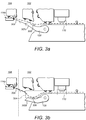
- Figures 3a and 3b show the printing system 100 with the media guide 120 of the printer 102 in a first position 302a and a second position 302b.
- the media guide 120 is in the first position 302a in which it is arranged to guide the leading edge of the substrate 106 to one of the downstream media paths 114a, 114b, 114c. If the media guide 120 is already in the first position 302a it may remain there at step S202. If the media guide is not in the first position 302a it may be moved to the first position 302a at step S202.
- the first position 302a may be a position suitable to guide the substrate 106 to any one of the downstream media paths 114a, 114b, 114c.
- the media guide 120 is moved to the second position 302b.
- the second position 302b is spaced apart from the first position 302a to form a buffer region 304 into which an amount of media substrate 106 can collect.
- the media guide 120 therefore performs both the function of guiding the substrate 106 to a desired downstream media path 114a, 114b, 114c and the function of creating the buffer region 304.
- Figure 3a schematically illustrates the media guide 120 in the first position 302a.
- the first position 302a is one in which the substrate 106 is to be guided from the printer 102 to the accessory device 104.
- the media guide 120 of the printer 102 is in the first position 302a, the media guide 120 overlaps an interface 308 of the accessory device 104 (referred to hereinafter simply as the accessory interface 308).
- Figure 3b schematically illustrates the media guide 120 in the second position 302b, which is spaced apart (i.e. below) the first position 302a. As shown in Figure 3b , with the media guide 120 in the second position 302b a buffer region 304 is created into which an amount of the substrate 106 can collect.
- the substrate 106 is able to form a loop or curve within the buffer region 304, thereby effectively mechanically decoupling a portion of the substrate 106 in the print zone 110 from a portion of substrate 106 in the respective downstream media path 114a, 114b, 114c. This prevents forces directed towards or away from the downstream portion of the substrate 106 from pushing or pulling on the region of substrate 106 in the print zone 110.
- Utilizing the media guide 120 to form the buffer region 304 enables buffering of substrate 106, and control of the buffered substrate 106, for multiple downstream media paths 114a, 114b, 114c. This results in a buffering solution that is less complex and less costly than existing solutions.
- the media guide 120 depicted in Figures 3a and 3b includes, on an upper surface of the media guide 120, a sensor 306.
- the sensor 306 is arranged to detect the extent by which the substrate 106 forms a loop i.e. the amount of substrate 106 in the buffer region 304.
- Providing the sensor 306 on the media guide 120 enables the use of a sensor 306 with a short detection range, or even a contact sensor.
- the sensor 306 can therefore be provided at relatively little expense.
- the sensor 306 may be a non-contact sensor capable of sensing a distance between the media guide 120 and the substrate 106 in the buffer region 304.
- the sensor 306 may be a photoelectric (optical) sensor, an ultrasonic sensor, or any other sensor suitable for detecting the substrate 106.
- the sensor 306 may be arranged to provide a signal to the printer 102 when the amount of substrate 106 in the buffer region 304 is at a minimum level and to provide another signal to the printer 102 when the amount of substrate 106 in the buffer region 304 is at a maximum level. Alternatively or additionally the sensor 306 may provide signals indicative of multiple positions of the substrate 106 between the maximum and minimum levels.
- the amount of substrate 106 collected in the buffer region 304 may be controlled dynamically using feedback control in which the printer 102 provides a target speed to the accessory device 104 based on the signals provided by the sensor 306 that are indicative of the detected amount of substrate 106 in the buffer region 304.
- the second position 302b may be varied so as to keep the separation between the sensor 306 and the substrate 106 within the range of the sensor 306.
- the printer 102 may be arranged to maintain a substantially constant separation between the sensor 306 and the substrate 106. The position of the media guide 120 may thereby be used to determine the amount of substrate 106 in the buffer region 304.
- the sensor 306 may be an electro-mechanical contact sensor that provides a signal dependent on whether or not the sensor 306 is in contact with the substrate 106.
- the signal may be provided to the printer 102 (or to a processor used to control functions of the printer 102).
- the printer 102 may control the position of the media guide 120, and therefore the sensor 306, on the basis of the signal from the sensor 306. For example, where the sensor 306 provides a signal indicating that it is not in contact with the substrate 106, then the media guide 120 may be moved upwardly until the signal provided by the sensor 306 indicates that it is in contact with the substrate 106.
- the media guide 120 may be moved downwardly until the signal provided by the sensor 306 indicates that it is in not contact with the substrate 106.
- the printer 102 may thereby control the position of the media guide 120 dynamically such that its position follows a bottom of the loop of substrate 106.
- the media guide 120 may include a positional encoder or some other means of determining its position. The position of the media guide 120 may thus be used to determine an amount of substrate 106 collected in the buffer region 304 for control of the amount of substrate 106 in the buffer region 304.
- the printer 102 may be arranged so that the sensor 306 is arranged to sense the non-printed side of the substrate 106. This enables reliable detection of the amount of substrate 106 collected in the buffer region 304 without marking or scratching the printed side of the substrate 106.
- the printer 102 may be arranged so that the sensor 306 is arranged to contact the printed side of the substrate 106.
- the amount of substrate 106 that is to be collected in the buffer region 304 may be predefined for a range of print modes, printing speeds, and/or substrate type.
- the predetermined amount of substrate 106 that is collected for a relatively stiffer substrate 106 may be greater than the predetermined amount for a relatively less stiff substrate 106.
- the amount of substrate 106 in the buffer region 304 may be controlled by changing the relative speeds at which the printer 102 and/or the accessory device 104 advance the substrate 106.
- the speed at which the accessory device 104 advances the substrate 106 is controlled relative to the speed of the printer 102, to control the amount of substrate 106 collected in the buffer region 304.
- the speed at which the accessory device 104 advances the substrate 106 is decreased when more buffer is needed (i.e. when the buffer is close to being empty) and increased when less buffer is needed (i.e. when the buffer region 304 is close to being full).
- Figure 4 shows, in plan view, an example of how the media guide 120 and an accessory interface 308 can be arranged to enable the media guide 120 to move from the first position 302a to the second position 302b whilst being able to form an overlap with the accessory interface 308 when in the first position 302a.
- an external edge 402 of the media guide 120 and an external edge 404 of the accessory interface 308 intermesh to form a substantially continuous surface, when the media guide 120 is in the first position 302a.
- each of the edges 402, 404 has a square-wave shape.
- the edges 402, 404 could have any shape suitable for enabling the edges 402, 404 to intermesh. This provides continuous support of the substrate 106 as it passes from the printer 102 to the accessory 104 and helps to avoid jams during the transfer.
- the loop of substrate 106 that forms in the buffer region 304 loops downwardly so that the bottom of the loop can be detected by the sensor 306, and so that the substrate 106 does not contact a ceiling above the substrate 106 in the buffer region 304.
- Figure 5 illustrates an accessory device 500 arranged to improve the ability of the printing system 100 to ensure that the loop of substrate 106 forms downwardly.
- the accessory device 500 comprises an input roller 502 and a pinch roller 504.
- the pinch roller 504 is separated from the input roller 502 by an amount sufficient to enable the substrate 106 to be guided between the input and pinch rollers 504, 502.
- An axis of rotation of the pinch roller 504, is vertically offset with respect to an axis of rotation of the input roller 502.
- the axis of rotation of the pinch roller 504 is vertically offset with respect to an axis of rotation of the input roller 502 by approximately 20° in a direction toward the printer 102.
- the pinch roller 504 applies a friction force resisting the downstream flow of the substrate 106.
- the relative offset of the pinch roller 504 with respect to the input roller 502 creates a vertical component to the friction force (resistance), which is transmitted along the substrate 106 in an upstream direction and which pushes the substrate 106 in a downward direction.
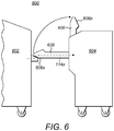
- Figure 6 shows an example of an arrangement of a printing system 600 in which a printer 602 is connectable to an accessory device 604 via a bridge arm 606.
- the bridge arm 606 is shown in two positions, a connected position 606a and a disconnected position 606b.
- the bridge arm 606 forms the downstream media path 114a, along which the substrate is transported following transfer through the print zone 110 (not shown).
- the accessory interface 308 In order for the accessory interface 308 to intermesh with the media guide 120, the accessory interface 308 extends some way into the printer 102. Furthermore, as described above with reference to Figure 4 , to avoid jams, the accessory interface 308 is intermeshed with the media guide 120 of the printer 102. Therefore, in order for bridge arm 606 to move from the connected position 606a to the disconnected position 606b, the accessory interface 308 is arranged to be retracted when the bridge arm 606 is not in the connected position 606a.
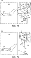
- Figures 7a and 7b show an example of a retraction mechanism 700 for retracting the accessory interface 308.
- the accessory interface 308 is connected to the accessory device 104 by a pivot 702.
- the lever arm 704 is arranged to engage a reference datum 706 located on the printer 102.
- the mechanism 700 includes a biasing spring 708 that is arranged to pull the accessory interface 308 into the accessory device 104 (specifically into the bridge arm 606).
- Figure 7a shows the position of the mechanism 700 when no force is applied to the lever arm 704 i.e. when the bridge arm 606 is in the disconnected position 606b.
- the accessory interface 308 is retracted to within the accessory device 104 by the biasing force of the spring 708. This enables the bridge arm 606 to be moved from the disconnected position 606b to the connected position 606a (and the reverse operation), without the accessory interface 308 coming into contact with the printer 102.
- Figure 7b shows the mechanism 700 when the bridge arm 606 is moved to the connected position 606a.
- the reference datum 706 engages the lever arm 704 to apply a force countering the biasing force of the spring 708.
- the resulting force causes the mechanism 700 to rotate about the pivot 702 in turn causing the accessory interface 308 to extend from the accessory device 104 and protrude into the printer 102.
- This illustrative mechanism 700 therefore provides an easy method of attaching and detaching the accessory device 104 to/from the printer 102 that is also robust against jams.
- an upstream accessory device may perform one or more functions before the printer 102 has printed to the substrate 106.
- an upstream accessory device may be a high-capacity input tray, a roll unwinding device, a substrate primer, or another printer.
Landscapes
- Engineering & Computer Science (AREA)
- Mechanical Engineering (AREA)
- Physics & Mathematics (AREA)
- General Physics & Mathematics (AREA)
- Ink Jet (AREA)
- Accessory Devices And Overall Control Thereof (AREA)
- Feeding Of Articles By Means Other Than Belts Or Rollers (AREA)
Claims (13)
- Druckvorrichtung (102, 602), die Folgendes umfasst:eine Medienführung (120), die dazu angeordnet ist, ein bedruckbares Mediensubstrat (106) von einem vorgeschalteten Medienpfad (112) hin zu einem Eingang der Druckvorrichtung oder weg von einem Ausgang der Druckvorrichtung hin zu einem nachgeschalteten Medienpfad (114a, 114b, 114c) zu führen, wobei die Medienführung bewegbar ist zwischen:(i) einer ersten Position (302a), die dazu angeordnet ist, das bedruckbare Mediensubstrat entlang eines jeweiligen Medienpfads (114a) zu führen; und(ii) einer zweiten Position (302b), die von der ersten Position beabstandet ist, um einen Pufferbereich (304) auszubilden, in dem sich eine variable Menge an bedruckbarem Mediensubstrat sammeln kann, wobei die zweite Position variabel ist, um die Größe des Pufferbereichs (304) zu variieren;
undeinen Sensor (306), der dazu angeordnet ist, das Ausmaß zu erfassen, in dem das Substrat in dem Pufferbereich (304) eine Schlaufe ausbildet, und der Druckvorrichtung ein Signal bereitzustellen, welches das erfasste Ausmaß angibt,dadurch gekennzeichnet, dass der Sensor (306) auf der Medienführung (120) angeordnet ist. - Druckvorrichtung nach Anspruch 1, die dazu angeordnet ist, auf der Grundlage des erfassten Ausmaßes die Menge an in dem Pufferbereich (304) gesammeltem Mediensubstrat zu steuern.
- Druckvorrichtung nach Anspruch 1 oder Anspruch 2, die dazu angeordnet ist, auf der Grundlage des erfassten Ausmaßes eine Medienvorschubgeschwindigkeit einer Zubehörvorrichtung (104, 604) bezogen auf eine Medienvorschubgeschwindigkeit der Druckvorrichtung zu steuern.
- Druckvorrichtung nach Anspruch 3, die dazu angeordnet ist, ein Steuersignal bereitzustellen, das die Medienvorschubgeschwindigkeit angibt, mit der die Zubehörvorrichtung (104, 604) arbeiten soll.
- Druckvorrichtung nach einem von Anspruch 3 oder Anspruch 4, die dazu angeordnet ist, ein erstes Steuersignal zum Verringern der Medienvorschubgeschwindigkeit der Zubehörvorrichtung (104, 604) bereitzustellen, wenn das erfasste Ausmaß unter einem ersten Schwellenwert liegt, und ein zweites Steuersignal zum Erhöhen der Medienvorschubgeschwindigkeit der Zubehörvorrichtung (104, 604) bereitzustellen, wenn das erfasste Ausmaß über einem zweiten Schwellenwert liegt.
- Druckvorrichtung nach einem von Anspruch 1 bis Anspruch 5, wobei die zweite Position (302b) auf der Grundlage des erfassten Ausmaßes variiert wird.
- Druckvorrichtung nach einem vorangehenden Anspruch, wobei die Druckvorrichtung mehrere nachgeschaltete Medienpfade (114a, 114b, 114c) umfasst und in der ersten Position (302a) die Medienführung (120) dazu angeordnet ist, das bedruckbare Mediensubstrat entlang eines der mehreren nachgeschalteten Medienpfade zu führen.
- Druckvorrichtung nach einem vorangehenden Anspruch, wobei die variable Menge an Mediensubstrat sich unter einem jeweiligen Medienpfad sammeln kann.
- Verfahren zum Betreiben einer Druckvorrichtung (102, 602), die eine bewegbare Medienführung (120) umfasst, wobei das Verfahren Folgendes umfasst:Anordnen der Medienführung in einer ersten Position (302a), die dazu angeordnet ist, ein bedruckbares Mediensubstrat (106) von einem vorgeschalteten Medienpfad (112) hin zu einem Eingang der Druckvorrichtung oder weg von einem Ausgang der Druckvorrichtung hin zu einem nachgeschalteten Medienpfad (114a, 114b, 114c) zu führen; undBewegen der Medienführung (120) in eine zweite Position (302b), die von der ersten Position (302a) beabstandet ist, um einen Pufferbereich (304) auszubilden, in dem sich eine variable Menge an Mediensubstrat sammeln kann;dadurch gekennzeichnet, dass es ferner Folgendes umfasst:Erfassen des Ausmaßes, in dem das Substrat in dem Pufferbereich (304) eine Schlaufe ausbildet, mit einem Sensor (306), der auf der Medienführung (120) angeordnet ist; undBereitstellen eines Signals, welches das erfasste Ausmaß angibt, an die Druckvorrichtung.
- Drucksystem, das eine Zubehörvorrichtung (104, 604) und eine Druckvorrichtung nach einem von Anspruch 1 bis Anspruch 8 umfasst.
- Drucksystem nach Anspruch 10, wobei die Zubehörvorrichtung (104) eine einziehbare Schnittstelle (308) umfasst, die dazu angeordnet ist, in einen Ausgang der Druckvorrichtung einzugreifen.
- Drucksystem nach Anspruch 11, wobei die einziehbare Schnittstelle (308) bewegbar ist zwischen:einer ersten Position, in der die einziehbare Schnittstelle (308) sich von dem Zubehör (104) aus erstreckt, um in die Medienführung (120) der Druckvorrichtung einzugreifen; undeiner zweiten Position, in der die einziehbare Schnittstelle (308) sich in eine eingezogene Position innerhalb des Zubehörs (104) zurückzieht.
- Drucksystem nach Anspruch 11 oder Anspruch 12, wobei die Medienführung (120) der Druckvorrichtung und die einziehbare Schnittstelle (308) des Zubehörs (104) ineinandergreifen.
Applications Claiming Priority (1)
| Application Number | Priority Date | Filing Date | Title |
|---|---|---|---|
| PCT/EP2014/061754 WO2015185147A1 (en) | 2014-06-05 | 2014-06-05 | Printing device, method of operating a printing device, and a printing system |
Publications (2)
| Publication Number | Publication Date |
|---|---|
| EP3152142A1 EP3152142A1 (de) | 2017-04-12 |
| EP3152142B1 true EP3152142B1 (de) | 2020-04-22 |
Family
ID=51022295
Family Applications (1)
| Application Number | Title | Priority Date | Filing Date |
|---|---|---|---|
| EP14733107.8A Active EP3152142B1 (de) | 2014-06-05 | 2014-06-05 | Druckvorrichtung, entsprechendes drucksystem, und verfahren zum betrieb einer druckvorrichtung |
Country Status (4)
| Country | Link |
|---|---|
| US (1) | US10035672B2 (de) |
| EP (1) | EP3152142B1 (de) |
| CN (1) | CN106458496B (de) |
| WO (1) | WO2015185147A1 (de) |
Families Citing this family (3)
| Publication number | Priority date | Publication date | Assignee | Title |
|---|---|---|---|---|
| US10999457B2 (en) * | 2017-09-07 | 2021-05-04 | Hewlett-Packard Development Company, L.P. | Stapling sensors to indicate movement of a stapling device |
| BR112020022248A2 (pt) * | 2018-07-23 | 2021-02-23 | Hewlett-Packard Development Company, L.P. | transferência de mídia |
| CN113646180A (zh) * | 2019-04-29 | 2021-11-12 | 惠普发展公司, 有限责任合伙企业 | 介质压痕机 |
Citations (4)
| Publication number | Priority date | Publication date | Assignee | Title |
|---|---|---|---|---|
| JPH0550318U (ja) * | 1991-12-04 | 1993-07-02 | セイコー電子工業株式会社 | 記録用紙駆動装置 |
| US5326093A (en) * | 1993-05-24 | 1994-07-05 | Xerox Corporation | Universal interface module interconnecting various copiers and printers with various sheet output processors |
| US20050156373A1 (en) * | 2004-01-16 | 2005-07-21 | Fuji Photo Film Co., Ltd. | Feeding device for sheet material and image recording apparatus for recording an image thereon |
| US20100066009A1 (en) * | 2008-09-18 | 2010-03-18 | Konica Minolta Business Technologies, Inc. | Image forming apparatus |
Family Cites Families (20)
| Publication number | Priority date | Publication date | Assignee | Title |
|---|---|---|---|---|
| JPH06191686A (ja) | 1992-12-24 | 1994-07-12 | Ricoh Co Ltd | 給紙装置 |
| JP3061552B2 (ja) | 1995-08-09 | 2000-07-10 | キヤノンアプテックス株式会社 | シ−ト後処理装置及びそれを備えた画像形成装置 |
| EP0769467B1 (de) | 1995-10-17 | 2002-06-05 | Sharp Kabushiki Kaisha | Bogenausgabevorrichtung |
| JP2887751B2 (ja) * | 1997-06-09 | 1999-04-26 | 株式会社東京機械製作所 | 印刷紙搬送列からの印刷紙小部数抜取装置 |
| US6422557B1 (en) | 1997-09-12 | 2002-07-23 | Canon Kabushiki Kaisha | Image forming apparatus having a plurality of sheet stacking means |
| US6231045B1 (en) | 1998-06-12 | 2001-05-15 | Ricoh Company, Ltd. | Finisher for an image forming apparatus |
| US6055409A (en) * | 1998-12-18 | 2000-04-25 | Xerox Corporation | Sheet pre-transfer device |
| DE19905263C1 (de) * | 1999-02-09 | 2000-01-05 | Roland Man Druckmasch | Vorrichtung und Verfahren zur Probebogenentnahme |
| JP2002258639A (ja) | 2001-03-06 | 2002-09-11 | Murata Mach Ltd | 画像形成装置 |
| JP4086525B2 (ja) * | 2001-04-16 | 2008-05-14 | 株式会社リコー | シート搬送装置及び画像形成装置 |
| US6974128B2 (en) * | 2003-06-10 | 2005-12-13 | Xerox Corporation | Sheet registration deskew with plural arcuate independently repositionable baffles |
| JP4630631B2 (ja) | 2004-10-29 | 2011-02-09 | キヤノン株式会社 | 画像形成装置 |
| US7957688B2 (en) | 2006-09-21 | 2011-06-07 | Sharp Kabushiki Kaisha | Image forming method and image forming apparatus |
| JP4963435B2 (ja) | 2007-03-27 | 2012-06-27 | キヤノン株式会社 | シート処理装置及び画像形成装置 |
| JP4886018B2 (ja) * | 2009-10-23 | 2012-02-29 | シャープ株式会社 | 画像形成装置 |
| JP2012063383A (ja) | 2010-09-14 | 2012-03-29 | Ricoh Co Ltd | 保守支援装置及び画像形成システム |
| EP2711318B1 (de) * | 2012-09-25 | 2015-08-12 | Multigraf AG | Vorrichtung und Verfahren zur Förderung von Bogen sowie Fördersystem |
| JP2014114152A (ja) * | 2012-12-12 | 2014-06-26 | Canon Inc | シート搬送装置及び画像形成装置 |
| CN203582061U (zh) * | 2013-09-09 | 2014-05-07 | 美迪亚印刷设备(杭州)有限公司 | 供排版机构 |
| US9688500B2 (en) * | 2015-01-08 | 2017-06-27 | Crane Payment Innovations, Inc. | Compact document bundler |
-
2014
- 2014-06-05 EP EP14733107.8A patent/EP3152142B1/de active Active
- 2014-06-05 CN CN201480079566.6A patent/CN106458496B/zh active Active
- 2014-06-05 US US15/316,400 patent/US10035672B2/en active Active
- 2014-06-05 WO PCT/EP2014/061754 patent/WO2015185147A1/en not_active Ceased
Patent Citations (4)
| Publication number | Priority date | Publication date | Assignee | Title |
|---|---|---|---|---|
| JPH0550318U (ja) * | 1991-12-04 | 1993-07-02 | セイコー電子工業株式会社 | 記録用紙駆動装置 |
| US5326093A (en) * | 1993-05-24 | 1994-07-05 | Xerox Corporation | Universal interface module interconnecting various copiers and printers with various sheet output processors |
| US20050156373A1 (en) * | 2004-01-16 | 2005-07-21 | Fuji Photo Film Co., Ltd. | Feeding device for sheet material and image recording apparatus for recording an image thereon |
| US20100066009A1 (en) * | 2008-09-18 | 2010-03-18 | Konica Minolta Business Technologies, Inc. | Image forming apparatus |
Also Published As
| Publication number | Publication date |
|---|---|
| CN106458496A (zh) | 2017-02-22 |
| US20170152121A1 (en) | 2017-06-01 |
| EP3152142A1 (de) | 2017-04-12 |
| US10035672B2 (en) | 2018-07-31 |
| CN106458496B (zh) | 2018-04-17 |
| WO2015185147A1 (en) | 2015-12-10 |
Similar Documents
| Publication | Publication Date | Title |
|---|---|---|
| US9415960B2 (en) | Printing apparatus and printing method | |
| GB2485037A (en) | Substrate media registration system and method in a printing system | |
| JP2010054855A (ja) | 画像形成装置 | |
| US9550641B2 (en) | Paper feeding device | |
| US9079426B2 (en) | Duplexing web press with drying time control | |
| JP5631117B2 (ja) | 記録装置、検出方法、および検出装置 | |
| US8690276B2 (en) | Media flatness verification and preview mode | |
| JP2017132636A (ja) | 印刷システム | |
| WO2011162764A1 (en) | Web press and a method of initiating printing | |
| US8979236B1 (en) | Image forming apparatus | |
| US10035672B2 (en) | Printing device | |
| JP6111615B2 (ja) | 画像形成装置 | |
| JP5782940B2 (ja) | 液体吐出装置 | |
| EP3431425B1 (de) | Bogenuberführungsvorrichtung, dazugehöriges drucksystem, und verfahren zur bogenüberführung | |
| US8696104B1 (en) | Motion quality improvement by feed-forward torque control of imaging drum | |
| JP2010024006A (ja) | 画像形成装置 | |
| US20080080920A1 (en) | Printer and method of controlling printer | |
| JP5954234B2 (ja) | インクジェット記録装置 | |
| US9145006B1 (en) | Duplex printer for sheet and web printing | |
| US9096084B1 (en) | Printer for sheet and web printing | |
| JP6709250B2 (ja) | 記録装置 | |
| JP2010202370A (ja) | 画像形成装置 | |
| JP2009113265A (ja) | 記録装置 | |
| JP2010158844A (ja) | プリンタ | |
| JP2011111299A (ja) | 記録装置、及び搬送制御方法 |
Legal Events
| Date | Code | Title | Description |
|---|---|---|---|
| STAA | Information on the status of an ep patent application or granted ep patent |
Free format text: STATUS: THE INTERNATIONAL PUBLICATION HAS BEEN MADE |
|
| PUAI | Public reference made under article 153(3) epc to a published international application that has entered the european phase |
Free format text: ORIGINAL CODE: 0009012 |
|
| STAA | Information on the status of an ep patent application or granted ep patent |
Free format text: STATUS: REQUEST FOR EXAMINATION WAS MADE |
|
| 17P | Request for examination filed |
Effective date: 20161206 |
|
| AK | Designated contracting states |
Kind code of ref document: A1 Designated state(s): AL AT BE BG CH CY CZ DE DK EE ES FI FR GB GR HR HU IE IS IT LI LT LU LV MC MK MT NL NO PL PT RO RS SE SI SK SM TR |
|
| AX | Request for extension of the european patent |
Extension state: BA ME |
|
| DAX | Request for extension of the european patent (deleted) | ||
| RAP1 | Party data changed (applicant data changed or rights of an application transferred) |
Owner name: HEWLETT-PACKARD DEVELOPMENT COMPANY, L.P. |
|
| GRAP | Despatch of communication of intention to grant a patent |
Free format text: ORIGINAL CODE: EPIDOSNIGR1 |
|
| STAA | Information on the status of an ep patent application or granted ep patent |
Free format text: STATUS: GRANT OF PATENT IS INTENDED |
|
| RIC1 | Information provided on ipc code assigned before grant |
Ipc: G03G 15/00 20060101ALI20191129BHEP Ipc: B65H 20/32 20060101ALI20191129BHEP Ipc: B65H 7/02 20060101ALI20191129BHEP Ipc: B65H 29/52 20060101ALI20191129BHEP Ipc: B65H 29/58 20060101ALI20191129BHEP Ipc: B65H 5/36 20060101AFI20191129BHEP |
|
| INTG | Intention to grant announced |
Effective date: 20191219 |
|
| GRAS | Grant fee paid |
Free format text: ORIGINAL CODE: EPIDOSNIGR3 |
|
| GRAA | (expected) grant |
Free format text: ORIGINAL CODE: 0009210 |
|
| STAA | Information on the status of an ep patent application or granted ep patent |
Free format text: STATUS: THE PATENT HAS BEEN GRANTED |
|
| AK | Designated contracting states |
Kind code of ref document: B1 Designated state(s): AL AT BE BG CH CY CZ DE DK EE ES FI FR GB GR HR HU IE IS IT LI LT LU LV MC MK MT NL NO PL PT RO RS SE SI SK SM TR |
|
| REG | Reference to a national code |
Ref country code: CH Ref legal event code: EP |
|
| REG | Reference to a national code |
Ref country code: IE Ref legal event code: FG4D |
|
| REG | Reference to a national code |
Ref country code: DE Ref legal event code: R096 Ref document number: 602014064103 Country of ref document: DE |
|
| REG | Reference to a national code |
Ref country code: AT Ref legal event code: REF Ref document number: 1259817 Country of ref document: AT Kind code of ref document: T Effective date: 20200515 |
|
| REG | Reference to a national code |
Ref country code: LT Ref legal event code: MG4D |
|
| REG | Reference to a national code |
Ref country code: NL Ref legal event code: MP Effective date: 20200422 |
|
| PG25 | Lapsed in a contracting state [announced via postgrant information from national office to epo] |
Ref country code: SE Free format text: LAPSE BECAUSE OF FAILURE TO SUBMIT A TRANSLATION OF THE DESCRIPTION OR TO PAY THE FEE WITHIN THE PRESCRIBED TIME-LIMIT Effective date: 20200422 Ref country code: IS Free format text: LAPSE BECAUSE OF FAILURE TO SUBMIT A TRANSLATION OF THE DESCRIPTION OR TO PAY THE FEE WITHIN THE PRESCRIBED TIME-LIMIT Effective date: 20200822 Ref country code: FI Free format text: LAPSE BECAUSE OF FAILURE TO SUBMIT A TRANSLATION OF THE DESCRIPTION OR TO PAY THE FEE WITHIN THE PRESCRIBED TIME-LIMIT Effective date: 20200422 Ref country code: NO Free format text: LAPSE BECAUSE OF FAILURE TO SUBMIT A TRANSLATION OF THE DESCRIPTION OR TO PAY THE FEE WITHIN THE PRESCRIBED TIME-LIMIT Effective date: 20200722 Ref country code: PT Free format text: LAPSE BECAUSE OF FAILURE TO SUBMIT A TRANSLATION OF THE DESCRIPTION OR TO PAY THE FEE WITHIN THE PRESCRIBED TIME-LIMIT Effective date: 20200824 Ref country code: GR Free format text: LAPSE BECAUSE OF FAILURE TO SUBMIT A TRANSLATION OF THE DESCRIPTION OR TO PAY THE FEE WITHIN THE PRESCRIBED TIME-LIMIT Effective date: 20200723 Ref country code: NL Free format text: LAPSE BECAUSE OF FAILURE TO SUBMIT A TRANSLATION OF THE DESCRIPTION OR TO PAY THE FEE WITHIN THE PRESCRIBED TIME-LIMIT Effective date: 20200422 Ref country code: LT Free format text: LAPSE BECAUSE OF FAILURE TO SUBMIT A TRANSLATION OF THE DESCRIPTION OR TO PAY THE FEE WITHIN THE PRESCRIBED TIME-LIMIT Effective date: 20200422 |
|
| REG | Reference to a national code |
Ref country code: AT Ref legal event code: MK05 Ref document number: 1259817 Country of ref document: AT Kind code of ref document: T Effective date: 20200422 |
|
| PG25 | Lapsed in a contracting state [announced via postgrant information from national office to epo] |
Ref country code: LV Free format text: LAPSE BECAUSE OF FAILURE TO SUBMIT A TRANSLATION OF THE DESCRIPTION OR TO PAY THE FEE WITHIN THE PRESCRIBED TIME-LIMIT Effective date: 20200422 Ref country code: BG Free format text: LAPSE BECAUSE OF FAILURE TO SUBMIT A TRANSLATION OF THE DESCRIPTION OR TO PAY THE FEE WITHIN THE PRESCRIBED TIME-LIMIT Effective date: 20200722 Ref country code: RS Free format text: LAPSE BECAUSE OF FAILURE TO SUBMIT A TRANSLATION OF THE DESCRIPTION OR TO PAY THE FEE WITHIN THE PRESCRIBED TIME-LIMIT Effective date: 20200422 Ref country code: HR Free format text: LAPSE BECAUSE OF FAILURE TO SUBMIT A TRANSLATION OF THE DESCRIPTION OR TO PAY THE FEE WITHIN THE PRESCRIBED TIME-LIMIT Effective date: 20200422 |
|
| PG25 | Lapsed in a contracting state [announced via postgrant information from national office to epo] |
Ref country code: AL Free format text: LAPSE BECAUSE OF FAILURE TO SUBMIT A TRANSLATION OF THE DESCRIPTION OR TO PAY THE FEE WITHIN THE PRESCRIBED TIME-LIMIT Effective date: 20200422 |
|
| REG | Reference to a national code |
Ref country code: DE Ref legal event code: R097 Ref document number: 602014064103 Country of ref document: DE |
|
| PG25 | Lapsed in a contracting state [announced via postgrant information from national office to epo] |
Ref country code: SM Free format text: LAPSE BECAUSE OF FAILURE TO SUBMIT A TRANSLATION OF THE DESCRIPTION OR TO PAY THE FEE WITHIN THE PRESCRIBED TIME-LIMIT Effective date: 20200422 Ref country code: EE Free format text: LAPSE BECAUSE OF FAILURE TO SUBMIT A TRANSLATION OF THE DESCRIPTION OR TO PAY THE FEE WITHIN THE PRESCRIBED TIME-LIMIT Effective date: 20200422 Ref country code: DK Free format text: LAPSE BECAUSE OF FAILURE TO SUBMIT A TRANSLATION OF THE DESCRIPTION OR TO PAY THE FEE WITHIN THE PRESCRIBED TIME-LIMIT Effective date: 20200422 Ref country code: AT Free format text: LAPSE BECAUSE OF FAILURE TO SUBMIT A TRANSLATION OF THE DESCRIPTION OR TO PAY THE FEE WITHIN THE PRESCRIBED TIME-LIMIT Effective date: 20200422 Ref country code: IT Free format text: LAPSE BECAUSE OF FAILURE TO SUBMIT A TRANSLATION OF THE DESCRIPTION OR TO PAY THE FEE WITHIN THE PRESCRIBED TIME-LIMIT Effective date: 20200422 Ref country code: MC Free format text: LAPSE BECAUSE OF FAILURE TO SUBMIT A TRANSLATION OF THE DESCRIPTION OR TO PAY THE FEE WITHIN THE PRESCRIBED TIME-LIMIT Effective date: 20200422 Ref country code: RO Free format text: LAPSE BECAUSE OF FAILURE TO SUBMIT A TRANSLATION OF THE DESCRIPTION OR TO PAY THE FEE WITHIN THE PRESCRIBED TIME-LIMIT Effective date: 20200422 Ref country code: CZ Free format text: LAPSE BECAUSE OF FAILURE TO SUBMIT A TRANSLATION OF THE DESCRIPTION OR TO PAY THE FEE WITHIN THE PRESCRIBED TIME-LIMIT Effective date: 20200422 Ref country code: ES Free format text: LAPSE BECAUSE OF FAILURE TO SUBMIT A TRANSLATION OF THE DESCRIPTION OR TO PAY THE FEE WITHIN THE PRESCRIBED TIME-LIMIT Effective date: 20200422 |
|
| REG | Reference to a national code |
Ref country code: CH Ref legal event code: PL |
|
| PG25 | Lapsed in a contracting state [announced via postgrant information from national office to epo] |
Ref country code: SK Free format text: LAPSE BECAUSE OF FAILURE TO SUBMIT A TRANSLATION OF THE DESCRIPTION OR TO PAY THE FEE WITHIN THE PRESCRIBED TIME-LIMIT Effective date: 20200422 Ref country code: PL Free format text: LAPSE BECAUSE OF FAILURE TO SUBMIT A TRANSLATION OF THE DESCRIPTION OR TO PAY THE FEE WITHIN THE PRESCRIBED TIME-LIMIT Effective date: 20200422 |
|
| PLBE | No opposition filed within time limit |
Free format text: ORIGINAL CODE: 0009261 |
|
| STAA | Information on the status of an ep patent application or granted ep patent |
Free format text: STATUS: NO OPPOSITION FILED WITHIN TIME LIMIT |
|
| 26N | No opposition filed |
Effective date: 20210125 |
|
| PG25 | Lapsed in a contracting state [announced via postgrant information from national office to epo] |
Ref country code: LU Free format text: LAPSE BECAUSE OF NON-PAYMENT OF DUE FEES Effective date: 20200605 |
|
| REG | Reference to a national code |
Ref country code: BE Ref legal event code: MM Effective date: 20200630 |
|
| PG25 | Lapsed in a contracting state [announced via postgrant information from national office to epo] |
Ref country code: LI Free format text: LAPSE BECAUSE OF NON-PAYMENT OF DUE FEES Effective date: 20200630 Ref country code: IE Free format text: LAPSE BECAUSE OF NON-PAYMENT OF DUE FEES Effective date: 20200605 Ref country code: CH Free format text: LAPSE BECAUSE OF NON-PAYMENT OF DUE FEES Effective date: 20200630 |
|
| PG25 | Lapsed in a contracting state [announced via postgrant information from national office to epo] |
Ref country code: SI Free format text: LAPSE BECAUSE OF FAILURE TO SUBMIT A TRANSLATION OF THE DESCRIPTION OR TO PAY THE FEE WITHIN THE PRESCRIBED TIME-LIMIT Effective date: 20200422 Ref country code: BE Free format text: LAPSE BECAUSE OF NON-PAYMENT OF DUE FEES Effective date: 20200630 |
|
| PG25 | Lapsed in a contracting state [announced via postgrant information from national office to epo] |
Ref country code: TR Free format text: LAPSE BECAUSE OF FAILURE TO SUBMIT A TRANSLATION OF THE DESCRIPTION OR TO PAY THE FEE WITHIN THE PRESCRIBED TIME-LIMIT Effective date: 20200422 Ref country code: MT Free format text: LAPSE BECAUSE OF FAILURE TO SUBMIT A TRANSLATION OF THE DESCRIPTION OR TO PAY THE FEE WITHIN THE PRESCRIBED TIME-LIMIT Effective date: 20200422 Ref country code: CY Free format text: LAPSE BECAUSE OF FAILURE TO SUBMIT A TRANSLATION OF THE DESCRIPTION OR TO PAY THE FEE WITHIN THE PRESCRIBED TIME-LIMIT Effective date: 20200422 |
|
| PG25 | Lapsed in a contracting state [announced via postgrant information from national office to epo] |
Ref country code: MK Free format text: LAPSE BECAUSE OF FAILURE TO SUBMIT A TRANSLATION OF THE DESCRIPTION OR TO PAY THE FEE WITHIN THE PRESCRIBED TIME-LIMIT Effective date: 20200422 |
|
| PGFP | Annual fee paid to national office [announced via postgrant information from national office to epo] |
Ref country code: FR Payment date: 20230523 Year of fee payment: 10 |
|
| PGFP | Annual fee paid to national office [announced via postgrant information from national office to epo] |
Ref country code: GB Payment date: 20230523 Year of fee payment: 10 |
|
| GBPC | Gb: european patent ceased through non-payment of renewal fee |
Effective date: 20240605 |
|
| PG25 | Lapsed in a contracting state [announced via postgrant information from national office to epo] |
Ref country code: FR Free format text: LAPSE BECAUSE OF NON-PAYMENT OF DUE FEES Effective date: 20240630 |
|
| PG25 | Lapsed in a contracting state [announced via postgrant information from national office to epo] |
Ref country code: GB Free format text: LAPSE BECAUSE OF NON-PAYMENT OF DUE FEES Effective date: 20240605 |
|
| REG | Reference to a national code |
Ref country code: DE Ref legal event code: R082 Ref document number: 602014064103 Country of ref document: DE Representative=s name: NOVAGRAAF BREVETS, FR |
|
| PGFP | Annual fee paid to national office [announced via postgrant information from national office to epo] |
Ref country code: DE Payment date: 20250724 Year of fee payment: 13 |