EP3148025A1 - Élément de scellement - Google Patents
Élément de scellement Download PDFInfo
- Publication number
- EP3148025A1 EP3148025A1 EP15812206.9A EP15812206A EP3148025A1 EP 3148025 A1 EP3148025 A1 EP 3148025A1 EP 15812206 A EP15812206 A EP 15812206A EP 3148025 A1 EP3148025 A1 EP 3148025A1
- Authority
- EP
- European Patent Office
- Prior art keywords
- electric wire
- rubber stopper
- holes
- guide member
- sheath
- Prior art date
- Legal status (The legal status is an assumption and is not a legal conclusion. Google has not performed a legal analysis and makes no representation as to the accuracy of the status listed.)
- Granted
Links
Images


Classifications
-
- H—ELECTRICITY
- H02—GENERATION; CONVERSION OR DISTRIBUTION OF ELECTRIC POWER
- H02G—INSTALLATION OF ELECTRIC CABLES OR LINES, OR OF COMBINED OPTICAL AND ELECTRIC CABLES OR LINES
- H02G15/00—Cable fittings
- H02G15/013—Sealing means for cable inlets
-
- H—ELECTRICITY
- H01—ELECTRIC ELEMENTS
- H01B—CABLES; CONDUCTORS; INSULATORS; SELECTION OF MATERIALS FOR THEIR CONDUCTIVE, INSULATING OR DIELECTRIC PROPERTIES
- H01B7/00—Insulated conductors or cables characterised by their form
- H01B7/17—Protection against damage caused by external factors, e.g. sheaths or armouring
- H01B7/28—Protection against damage caused by moisture, corrosion, chemical attack or weather
- H01B7/282—Preventing penetration of fluid, e.g. water or humidity, into conductor or cable
-
- H—ELECTRICITY
- H01—ELECTRIC ELEMENTS
- H01R—ELECTRICALLY-CONDUCTIVE CONNECTIONS; STRUCTURAL ASSOCIATIONS OF A PLURALITY OF MUTUALLY-INSULATED ELECTRICAL CONNECTING ELEMENTS; COUPLING DEVICES; CURRENT COLLECTORS
- H01R13/00—Details of coupling devices of the kinds covered by groups H01R12/70 or H01R24/00 - H01R33/00
- H01R13/46—Bases; Cases
- H01R13/52—Dustproof, splashproof, drip-proof, waterproof, or flameproof cases
- H01R13/5205—Sealing means between cable and housing, e.g. grommet
-
- H—ELECTRICITY
- H02—GENERATION; CONVERSION OR DISTRIBUTION OF ELECTRIC POWER
- H02G—INSTALLATION OF ELECTRIC CABLES OR LINES, OR OF COMBINED OPTICAL AND ELECTRIC CABLES OR LINES
- H02G3/00—Installations of electric cables or lines or protective tubing therefor in or on buildings, equivalent structures or vehicles
- H02G3/22—Installations of cables or lines through walls, floors or ceilings, e.g. into buildings
-
- H—ELECTRICITY
- H02—GENERATION; CONVERSION OR DISTRIBUTION OF ELECTRIC POWER
- H02G—INSTALLATION OF ELECTRIC CABLES OR LINES, OR OF COMBINED OPTICAL AND ELECTRIC CABLES OR LINES
- H02G15/00—Cable fittings
- H02G15/02—Cable terminations
- H02G15/04—Cable-end sealings
- H02G15/043—Cable-end sealings with end caps, e.g. sleeve closed at one end
- H02G15/046—Cable-end sealings with end caps, e.g. sleeve closed at one end with bores or protruding portions allowing passage of cable conductors
-
- Y—GENERAL TAGGING OF NEW TECHNOLOGICAL DEVELOPMENTS; GENERAL TAGGING OF CROSS-SECTIONAL TECHNOLOGIES SPANNING OVER SEVERAL SECTIONS OF THE IPC; TECHNICAL SUBJECTS COVERED BY FORMER USPC CROSS-REFERENCE ART COLLECTIONS [XRACs] AND DIGESTS
- Y02—TECHNOLOGIES OR APPLICATIONS FOR MITIGATION OR ADAPTATION AGAINST CLIMATE CHANGE
- Y02A—TECHNOLOGIES FOR ADAPTATION TO CLIMATE CHANGE
- Y02A30/00—Adapting or protecting infrastructure or their operation
- Y02A30/14—Extreme weather resilient electric power supply systems, e.g. strengthening power lines or underground power cables
Definitions
- the present invention relates to a sealing member.
- Patent Document 1 a rubber stopper for collectively protecting multiple electric wires from water disclosed in JPH11-329567A (Patent Document 1) has been known.
- the rubber stopper includes multiple wire through holes through which the electric wires are passed, respectively. Outer peripheries of the electric wires are tightly held against inner walls of the respective through holes to tightly fit the electric wires in the rubber stopper. Furthermore, an outer periphery of the rubber stopper is tightly held against an inner wall of a rubber stopper attachment hole of a case to tightly fit the rubber stopper in the case.
- Patent Document 1 JPH11-329567A
- a cover is fitted on a rear end of the case via a locking portion so as to be removal.
- the cover includes wire through holes through which the wires are passed, respectively.
- a sealing member according to the present invention includes a rubber stopper and a rear guide member.
- the rubber stopper includes an electric wire through portion.
- the electric wire through portion includes through holes through which electric wires are passed, respectively.
- the rear guide member includes guide holes located more to a rear than the electric wire through portion in an extending direction in which the electric wires passed through the through holes extend and through which the electric wires are passed. The guide holes are aligned with the through holes of the rubber stopper.
- the electric wires are passed through the guide holes of the rear guide member and properly guided to the through holes, respectively. According to the configuration, the electric wires are tightly held against inner walls of the through holes, respectively. Therefore, air tightness between the rubber stopper and the electric wires is less likely to decrease.
- the rear guide member may include a lock portion for locking with the rubber stopper.
- the rubber stopper may include a lock catch portion with which the lock portion is engaged. The rubber stopper may be held at a position relative to the rear guide member with the lock portion engaged with the lock catch portion such that the through holes of the rubber stopper are aligned with the guide holes of the rear guide member.
- the guide holes are properly held at positions at which the guide holes are aligned with the through holes, respectively. Therefore, the air tightness between the rubber stopper and the electric wires is less likely to decrease.
- the sealing member may include a front guide member located more to a front than the electric wire through portion in the extending direction.
- the front guide member may include guide holes aligned with the plurality of through holes of the rubber stopper.
- the electric wires are guided from a side more to the front than the electric wire through portion in the extending direction to the through holes, respectively,. Furthermore, the electric wires are guided from a side more to the rear than the electric wire through portion in the extending direction to the through holes, respectively. Therefore, the air tightness between the rubber stopper and the electric wires is less likely to decrease.
- Electric wire-side lips may be formed on inner walls of the through holes.
- the electric wire-side lips may be tightly held against outer peripheries of the electric wires, respectively.
- the electric wire-side lips are tightly held against the outer peripheries of the electric wires. Therefore, the air tightness between the rubber stopper and the electric wires is less likely to decrease.
- the air tightness between the rubber stopper and the electric wires is less likely to decrease.
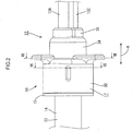
- FIGS. 1 to 19 A first embodiment including a sealing member 10 to which the present invention is applied will be described with reference to FIGS. 1 to 19 .
- This embodiment may be used for a wire harness for an electric parking brake installed in a vehicle (not illustrated).
- a horizontal direction in FIG. 2 corresponds to an extending direction A in which electric wires 13A, 13B, 13C and 13D extend.
- the right side in FIG. 2 corresponds to a front in the extending direction A and the left side in FIG. 2 corresponds to a rear in the extending direction A.
- the multicore cable 11 includes the electric wires 13A, 13B, 13C and 13D (four electric wires in this embodiment) wrapped in a sheath 14 that is made of insulating synthetic resin.
- the electric wires 13A, 13B, 13C and 13D include metal core wires (not illustrated), respectively. Outer peripheries of the core wires are covered with insulating films (not illustrated), respectively.
- the multicore cable 11 has a round cross section.
- four electric wires 13A, 13B, 13C and 13D include two kinds of electric wires 13A, 13B, 13C and 13D having different outer diameters.
- This embodiment includes a first electric wire 13A, a second electric wire 13B, a third electric wire 13C, and a fourth electric wire 13D.
- the first electric wire 13A and the second electric wire 13B are to be connected to a motor of the electric parking brake.
- the third electric wire 13C and the fourth electric wire 13D are for a sensor in an antilock brake system.
- the first electric wire 13A, the second electric wire 13B, the third electric wire 13C, and the fourth electric wire 13D have round cross-sections, respectively.
- the outer diameters of the first electric wire 13A and the second electric wire 13B are larger than the outer diameters of the third electric wire 13C and the fourth electric wire 13D.
- the outer diameters of the first electric wire 13A and the second electric wire 13B are about equal to each other.
- the outer diameters of the third electric wire 13C and the fourth electric wire 13D are about equal to each other. Portions of the first electric wire 13A, the second electric wire 13B, the third electric wire 13C, and the fourth electric wire 13D stick out of an end 14A of the sheath 14 of the multicore cable 11 and branch off.
- the sealing member 10 is attached to the end 14A of the sheath 14 of the multicore cable 11 and the portions of the first electric wire 13A, the second electric wire 13B, the third electric wire 13C, and the fourth electric wire 13D sticking out of the end 14A of the sheath 14 and branching off.
- the sealing member 10 restricts liquid such as water and oil from entering through the end 14A of the sheath 14.
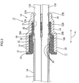
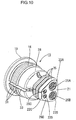
- the sealing member 10 includes a rubber stopper 15, a guide member 16 (an example of a rear guide member), and a cap 17 (an example of a front guide member).
- the rubber stopper 15 is fitted on the end 14A of the sheath 14.
- a guide member 16 is attached to an inside of the rubber stopper 15.
- the cap 17 is fitted on the rubber stopper 15.
- the rubber stopper 15 is fitted on the end 14A of the sheath 14.
- the rubber stopper 15 includes a sheath fitting portion 18 that is fitted on the end 14A of the sheath 14.
- the sheath fitting portion 18 has a hood shape that extends in an opposite direction to the end 14A of the sheath 14 (toward the left side in FIG. 3 ) and opens toward the opposite direction to the end 14A of the sheath 14 (toward the left side in FIG. 3 ).
- the sheath fitting portion 18 has a hood shape that extends toward the rear in the extending direction A and opens toward the rear in the extending direction A.
- a flange portion 19 is formed at an edge of the sheath fitting portion 18.
- the flange portion 19 projects outward in a radial direction of the sheath fitting portion 18.
- the sheath fitting portion 18 has a substantially tubular shape in a natural state.
- sheath-side lips 20 that project inward are formed on an inner periphery of the sheath fitting portion 18 annularly along the circumferential direction of the sheath fitting portion 18.
- the sheath fitting portion 18 is fitted on the end 14A of the sheath 14
- the sheath-side lips 20 are tightly held against the outer periphery of the sheath 14.
- the rubber stopper 15 is tightly fitted to the sheath 14.
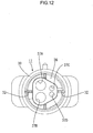
- the rubber stopper 15 includes an electric wire through portion 21 at an end opposite from the sheath fitting portion 18.
- the electric wire through portion 21 includes through holes 22A, 22B, 22C and 22D (four through holes in this embodiment) through which the first electric wire 13A, the second electric wire 13B, the third electric wire 13C, and the fourth electric wire 13D are passed, respectively.
- the through holes 22A, 22B, 22C and 22D include a first through hole 22A through which the first electric wire 13A is passed, a second through hole 22B through which the second electric wire 13B is passed, a third through hole 22C through which the third electric wire 13C is passed, and a fourth through hole 22D through which the fourth electric wire 13D is passed.
- the first to the fourth through holes 22A, 22B, 22C and 22D extend in the extending direction A.
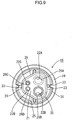
- the electric wire through portion 21 has a trapezoidal cross section with rounded corners.
- the cross section of the electric wire through portion 21 includes a long side 23, a short side 24 that is parallel to the long side 23 and shorter than the long side, and two oblique sides 25 that connect ends of the long side 23 to ends of the short side.
- the first through hole 22A and the second through hole 22B are formed side by side in a direction in which the long side 23 extends (the vertical direction in FIG. 9 ) in a portion of the electric wire through portion 21 closer to the long side 23.
- the third through hole 22C and the fourth through hole 22D are formed side by side in a direction in which the short side 24 extends (the vertical direction in FIG. 9 ) in a portion of the electric wire through portion 21 closer to the short side 24.
- An inner diameter of the first through hole 22A is slightly larger than the outer diameter of the first electric wire 13A.
- a first electric wire-side lip 26A is formed on an inner wall of the first through hole 22A annularly along the circumferential direction of the first through hole 22A.
- the first electric wire-side lip 26A is tightly held against the outer periphery of the first electric wire 13A when the first electric wire 13A is passed through the first through hole 22A.
- the rubber stopper 15 is tightly held against the first electric wire 13A.
- An inner diameter of the second through hole 22B is slightly larger than the outer diameter of the second electric wire 13B.
- a second electric wire-side lip 26B is formed on an inner wall of the second through hole 22B annularly along the circumferential direction of the second through hole 22B.
- the second electric wire-side lip 26B is tightly held against the outer periphery of the second electric wire 13B when the second electric wire 13B is passed through the second through hole 22B.
- the rubber stopper 15 is tightly held against the second electric wire 13B.
- An inner diameter of the third through hole 22C is slightly larger than the outer diameter of the third electric wire 13C.
- a third electric wire-side lip 26C is formed on an inner wall of the third through hole 22C annularly along the circumferential direction of the third through hole 22C.
- the third electric wire-side lip 26C is tightly held against the outer periphery of the third electric wire 13C when the third electric wire 13C is passed through the third through hole 22C.
- the rubber stopper 15 is tightly held against the third electric wire 13C.
- An inner diameter of the fourth through hole 22D is slightly larger than the outer diameter of the fourth electric wire 13D.
- a fourth electric wire-side lip 26D is formed on an inner wall of the fourth through hole 22D annularly along the circumferential direction of the fourth through hole 22D.
- the fourth electric wire-side lip 26D is tightly held against the outer periphery of the fourth electric wire 13D when the fourth electric wire 13D is passed through the fourth through hole 22D. According to the configuration, the rubber stopper 15 is held against the fourth electric wire 13D.
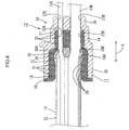
- the rubber stopper 15 includes a holding portion 28 between the sheath-side lips 20 and the electric wire through portion 21 inside the sheath fitting portion 18.
- the holding portion 28 is for holding the guide member 16 that includes guide holes 38A, 38B, 38C (examples of guide holes) and 38D through which the first electric wire 13A, the second electric wire 13B, the third electric wire 13C, and the fourth electric wire 13D are passed, respectively (four holes in this embodiment).
- the cap 17 made of synthetic resin is fitted on the rubber stopper 15.
- the cap 17 is fitted to the rubber stopper 15 from the end 14A of the sheath 14 from which the portions of the first electric wire 13A, the second electric wire 13B, the third electric wire 13C, and the forth electric wire 13D are exposed (from the right side in FIG. 3 ).
- the cap 17 is fitted to the rubber stopper 15 from the front in the extending direction A.
- the cap 17 includes a hole that extends from the end from which the first electric wire 13A, the second electric wire 13B, the third electric wire 13C, and the forth electric wire 13D are exposed toward the sheath 14 (toward the left side in FIG. 3 ). Namely, the cap 17 opens toward the rear in the extending direction. An opening edge of the cap 17 is brought into contact with the flange portion 19 of the rubber stopper 15 from the front in the extending direction A.
- the cap 17 includes a large diameter portion 30 that is fitted on the sheath fitting portion 18 of the rubber stopper 15 at a portion closer to the opening edge of the cap 17 (on the left side in FIG. 3 ).
- the large diameter portion 30 has a round cross section along an outline of the sheath fitting portion 18.
- An inner periphery of the large diameter portion 30 is tightly held against large diameter portion-side lips 31 formed on the outer periphery of the sheath fitting portion 18 (three lips in this embodiment).
- the large diameter portion-side lips 31 protrude outward from the outer periphery of the sheath fitting portion 18.
- the large diameter portion-side lips 31 are formed along the circumferential direction of the sheath fitting portion 18. With the large diameter portion-side lips 31 tightly held against the inner periphery of the large diameter portion 30 of the cap 17, the large diameter portion 30 of the cap 17 is tightly held against the sheath fitting portion 18 of the rubber stopper 15.
- the large diameter portion 30 of the cap 17 includes cap lock portions 32 (two cap lock portions in this embodiment) on an inner surface.
- the cap lock portions 32 have rib shapes that extend along a direction in which a hollow of the cap 17 extends.
- Two cap lock portions 32 are formed on the inner surface of the large diameter portion 30 at positions opposed to each other.
- the rubber stopper 15 includes two cap lock catch portions 33 in outer peripheries of the sheath fitting portion 18 and the holding portion 28.
- the cap lock portions 32 (two cap lock portions in this embodiment) are engaged in the cap lock catch portions 33, respectively.
- the cap lock catch portions 33 have groove shapes that extend in a direction in which the sheath fitting portion 18 extends.
- the cap lock catch portions 33 are formed at positions corresponding to the cap lock portions 32 of the large diameter portion 30, respectively.
- the large diameter portion 30 of the cap 17 fitted on the sheath fitting portion 18 of the rubber stopper 15 presses the sheath fitting portion 18 inward in the radial direction of the sheath fitting portion 18. Therefore, the sheath fitting portion 18 is pressed against the outer periphery of the sheath 14 from the outer side. As a result, the sheath-side lips 20 of the sheath fitting portion 18 are tightly contact with the outer periphery of the sheath 14.
- the cap 17 includes a small diameter portion 34 at a position farther from the opening of the cap 17 relative to the large diameter portion 30 (on the right side in FIG. 3 ).
- the small diameter portion 34 is fitted on the electric wire through portion 21 of the rubber stopper 15.
- An outer diameter of the small diameter portion 34 is smaller than the outer diameter of the large diameter portion 30.
- the small diameter portion 34 has a trapezoidal cross section with rounded corners along an outline of the electric wire through portion 21.
- an inner periphery of the small diameter portion 34 is tightly held against multiple small diameter-side lips 35 (three small diameter-side lips in this embodiment) formed on the outer periphery of the electric wire through portion 21.
- the small diameter-side lips 35 are formed on the outer periphery of the electric wire through portion 21 along the circumferential direction of the electric wire through portion 21 such that the small diameter-side lips 35 projects outward.
- the small diameter portion 34 of the cap 17 is fitted on the electric wire through portion 21 of the rubber stopper 15
- the small diameter portion 34 presses the electric wire through portion 21 inward in the radial direction of the electric wire through portion 21. Therefore, the electric wire through portion 21 is compressed by a force from the outer side.
- the first to the fourth wire-side lips 26A, 26B, 26C, 26D tightly contact the outer peripheries of the first to the fourth electric wire 13A, 13B, 13C and 13D, respectively.
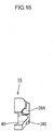
- the cap 17 includes an end wall 36 at an opposite side from the opening of the cap 17.
- the end wall 36 is located more to the front than the electric wire through portion 21 of the rubber stopper 15 in the extending direction A.
- the end wall 36 includes a first exiting hole 37A (an example of a guide hole), a second exiting hole 37B (an example of a guide hole), a third exiting hole 37C (an example of a guide hole), and a fourth exiting hole 37D (an example of a guide hole).
- the exiting holes 37A to 37D are through holes through which the first electric wire 13A, the second electric wire 13B, the third electric wire 13C, the fourth electric wire 13D exit from the cap 17, respectively.
- the first electric wire 13A is passed through the first exiting hole 37A
- the second electric wire 13B is passed through the second exiting hole 37B
- the third electric wire 13C is passed through the third exiting hole 37C
- the fourth electric wire 13D is passed through the fourth exiting hole 37D.
- the cap lock portions 32 of the large diameter portion 30 of the cap 17 engaged in the cap lock catch portions 33 of the sheath fitting portion 18 of the rubber stopper 15 a position of the rubber stopper 15 relative to the cap 17 is defined.
- the first to the fourth through holes 22A, 22B, 22C and 22D of the rubber stopper 15 are aligned with the first to the fourth exiting holes 37A, 37B, 37C and 37D of the cap 17, respectively.
- first through hole 22A is aligned with the first exiting hole 37A
- second through hole 22B is aligned with the second exiting hole 37B
- third through hole 22C is aligned with the third exiting hole 37C
- fourth through hole 22D is aligned with the fourth exiting hole 37D.
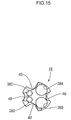
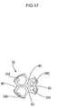
- the guide member 16 made of synthetic resin includes a first guide hole 38A, a second guide hole 38B, a third guide hole 38C, and a fourth guide hole 38D that are through holes through which the first electric wire 13A, the second electric wire 13B, the third electric wire 13C, and the fourth electric wire 13D are passed, respectively.
- the guide member 16 is located more to the rear than the electric wire through portion 21 in the extending direction A when the guide member 16 is held by the holding portion 28 of the rubber stopper 15.
- the rubber stopper 15 includes multiple guide member lock portions 39 (four guide member lock portions 39 in this embodiment) which protrude inward from the inner periphery of the holding portion 28.
- the guide member 16 includes multiple guide member lock catch portions 40 (four guide member lock catch portions 40 in this embodiment) in which the guide member lock portions 39 are fitted.
- the guide member lock catch portions 40 are recesses formed in the outer periphery of the guide member 16.
- the guide member lock catch portions 40 are located at positions corresponding to the guide member lock portions 39, respectively.
- the guide member lock portions 39 of the holding portion 28 of the rubber stopper 15 and the guide member lock catch portions 40 of the guide member 16 are engaged, respectively.
- the guide member 16 is held in a condition that a rotation of the guide member 16 in the circumferential direction of the guide member 16 relative to the rubber stopper 15.
- a position of the rubber stopper 15 relative to the guide member 16 is defined.
- the first to the fourth through holes 22A, 22B, 22C and 22D of the rubber stopper 15 are aligned with the first to the fourth guide holes 38A, 38B, 38C and 38D of the guide member 16, respectively.
- first through hole 22A is aligned with the first guide hole 38A
- second through hole 22B is aligned with the second guide hole 38B
- third through hole 22C is aligned with the third guide hole 38C
- fourth through hole 22D is aligned with the fourth guide hole 38D.
- the production process according to this embodiment is not limited to a production process described below.
- a portion of the sheath 14 of the multicore cable 11 is stripped by a known method.
- the portions of the first to the fourth electric wires 13A, 13B, 13C and 13D are exposed from the end 14A of the sheath 14.
- the first to the fourth electric wires 13A, 13B, 13C and 13D are passed through the first to the fourth guide holes 38A, 38B, 38C and 38D of the guide member 16, respectively.
- the first electric wire 13A is passed through the first guide hole 38A
- the second electric wire 13B is passed through the second guide hole 38B
- the third electric wire 13C is passed through the third guide hole 38C
- the fourth electric wire 13D is passed through the fourth guide hole 38D.
- the first to the fourth electric wires 13A, 13B, 13C and 13D are passed through the first to the fourth through holes 22A, 22B, 22C and 22D, respectively.
- the first electric wire 13A is passed through the first through hole 22A
- the second electric wire 13B is passed through the second through hole 22B
- the third electric wire 13C is passed through the third through hole 22C
- the fourth electric wire 13D is passed through the fourth through hole 22D.
- the rubber stopper 15 is moved to a position at which the guide member 16 is located.
- a position of the rubber stopper 15 relative to the guide member 16 is adjusted such that the first to the fourth through holes 22A, 22B, 22C and 22D of the rubber stopper 15 are aligned with the first to the fourth guide holes 38A, 38B, 38C and 38D of the guide member 16, respectively.
- guide member 16-side lock portions of the rubber stopper 15 are engaged in guide member 16-side lock catch portions of the guide member 16.
- the guide member 16 is held by the holding portion 28 of the rubber stopper 15 with the first to the fourth guide holes 38A, 38B, 38C and 38D of the guide member 16 aligned with the first to the fourth through holes 22A, 22B, 22C and 22D of the rubber stopper 15, respectively.
- the rubber stopper 15 is moved to the end 14A of the sheath 14 to fit the sheath fitting portion 18 of the rubber stopper 15 on the end 14A of the sheath 14.
- the first to the fourth electric wires 13A, 13B, 13C and 13D are passed through the first to the fourth exiting holes 37A, 37B, 37C and 37D of the cap 17, respectively.
- the first electric wire 13A is passed through the first exiting hole 37A
- the second electric wire 13B is passed through the second exiting hole 37B
- the third electric wire 13C is passed through the third exiting hole 37C
- the fourth electric wire 13D is passed through the fourth exiting hole 37D.
- the cap 17 is moved to a position at which the rubber stopper 15 is fitted on the end 14A of the sheath 14.
- a position of the cap 17 relative to the rubber stopper 15 is adjusted such that the first to the fourth exiting holes 37A, 37B, 37C and 37D of the cap 17 are aligned with the first to the fourth through holes 22A, 22B, 22C and 22D of the rubber stopper 15.
- the guide member 16-side lock portions of the rubber stopper 15 are engaged in the guide member 16-side lock catch portions of the guide member 16.
- the cap 17 is fitted on the rubber stopper 15 with the first to the fourth exiting holes 37A, 37B, 37C and 37D of the cap 17 aligned with the first to the fourth through holes 22A, 22B, 22C and 22D of the rubber stopper 15, respectively.
- the cap 17 is pushed until the cap 17 is brought into contact with the flange portion 19 of the rubber stopper 15.
- the sealing member 10 according to this embodiment is complete and a sealing structure 12 of the multicore cable 11 is formed (see FIG. 1 ).
- the first to the fourth electric wires 13A, 13B, 13C and 13D are passed through the first to the fourth exiting holes 37A, 37B, 37C and 37D of the cap 17, respectively, and through the first to the fourth guide holes 38A, 38B, 38C and 38D of the guide member 16, respectively.
- the first to the fourth electric wires 13A, 13B, 13C and 13D are properly guided to the first to the fourth through holes 22A, 22B, 22C and 22D, respectively. Therefore, the first to the fourth electric wires 13A, 13B, 13C and 13D are tightly held against the inner walls of the first to the fourth through holes 22A, 22B, 22C and 22D, respectively. Therefore, air tightness between the rubber stopper 15 and the first to the fourth electric wires 13A, 13B, 13C and 13D is less likely to decrease.
- the guide member 16 includes the guide member lock catch portions 40 for locking with the rubber stopper 15 and the rubber stopper 15 includes the guide member lock portions 39 that are engaged with the guide member lock catch portions 40.
- the position of the guide member 16 relative to the rubber stopper 15 is maintained at the position at which the first to the fourth guide holes 38A, 38B, 38C and 38D of the guide member 16 are aligned with the first to the fourth through holes 22A, 22B, 22C and 22D of the rubber stopper 15.
- the first to the fourth guide holes 38A, 38B, 38C and 38D of the guide member 16 are properly held at the position at which the first to the fourth guide holes 38A, 38B, 38C and 38D of the guide member 16 are aligned with the first to the fourth through holes 22A, 22B, 22C and 22D of the rubber stopper 15. Therefore, the air tightness between the rubber stopper 15 and the first to the fourth electric wires 13A, 13B, 13C and 13D is less likely to decrease.
- the cap 17 includes the cap lock portions 32 for locking with the rubber stopper 15 and the rubber stopper 15 includes the cap lock catch portions 33 with which the cap lock portions 32 are engaged. With the cap lock portions 32 engaged with the cap lock catch portions 33, the position of the cap 17 relative to the rubber stopper 15 is maintained at the position at which the first to the fourth exiting holes 37A, 37B, 37C and 37D of the cap 17 are aligned with the first to the fourth through holes 22A, 22B, 22C and 22D of the rubber stopper 15. According to the configuration, the first to the fourth exiting holes 37A, 37B, 37C and 37D are properly aligned with the first to the fourth through holes 22A, 22B, 22C and 22D. Therefore, the air tightness between the rubber stopper 15 and the first to the fourth electric wires 13A, 13B, 13C and 13D is less likely to decrease.
- the cap 17 is located more to the front than the electric wire through portion 21 in the extending direction A and the guide member 16 is located more to the rear than the electric wire through portion 21 in the extending direction A.
- the first to the fourth electric wires 13A, 13B, 13C and 13D are properly guided from a side more to the front than the electric wire through portion 21 in the extending direction A to the first to the fourth through holes 22A, 22B, 22C and 22D, respectively.
- the first to the fourth electric wires 13A, 13B, 13C and 13D are properly guided from a side more to the rear than the electric wire through portion 21 in the extending direction A to the first to the fourth through holes 22A, 22B, 22C and 22D, respectively. Therefore, the air tightness between the rubber stopper 15 and the first to the fourth electric wires 13A, 13B, 13C and 13D is less likely to decrease.
- the first to the fourth wire-side lips 26A, 26B, 26C and 26D that are tightly held against the outer peripheries of the first to the fourth electric wires 13A, 13B, 13C and 13D, respectively, are formed on the inner walls of the first to the fourth through holes 22A, 22B, 22C and 22D. Because the first to the fourth wire-side lips 26A, 26B, 26C and 26D are held against the outer peripheries of the first to the fourth electric wires 13A, 13B, 13C and 13D, respectively, the air tightness between the rubber stopper 15 and the first to the fourth electric wires 13A, 13B, 13C and 13D is less likely to decrease.
- the sealing member may be configured to include a positioning member that is a component different from the guide member and the rubber stopper. With the guide member positioned relative to the positioning member and the rubber stopper positioned relative to the positioning member, the through holes and the guide holes are positioned such that the through holes are aligned with the guide holes.
- the sealing member 10 includes both the gap 17 and the guide member 16.
- the sealing member 10 may include only the cap 17 or only the guide member 16.
- the multicore cable 11 may include two or three electric wires or five or more electric wires.
- the electric wires include two kinds of the electric wires having two different outer diameters. However, the electric wires may include three kinds of electric wires having three different outer diameters.
- the electric wires may have the same outer diameter.
- the electric wires may be shielded electric wires.
- the electric wires may be twisted electric wires each including multiple metal thin wires that are twisted together.
- the electric wires may be single-core electric wires each having metal poles as core wires. The electric wires may be selected as appropriate.
- the multicore cable 11 may be a cabtire cable or a multicore shielded electric wire that includes multiple electric wires wrapped in a shield layer.
- the multicore cable 11 can be selected from any cables as appropriate.
- sealing member 10 of the embodiment can block any type of liquid such as water, oil, and organic solvent.
- the guide member 16, the rubber stopper 15, and the cap 17 are attached in this sequence to the portion of the multicore cable 11 from which the sheath 14 is stripped to prepare the sealing member 10 and the sealing structure 12 of the multicore cable 11.
- the multicore cable 11 and the sealing member 10 may be assembled together by passing the electric wires of the multicore cable 11 without the sheath 14 through the sealing member 10 that is attached in advance.
Landscapes
- Engineering & Computer Science (AREA)
- Architecture (AREA)
- Civil Engineering (AREA)
- Structural Engineering (AREA)
- Connector Housings Or Holding Contact Members (AREA)
- Installation Of Indoor Wiring (AREA)
- Gasket Seals (AREA)
- Insulated Conductors (AREA)
Applications Claiming Priority (2)
| Application Number | Priority Date | Filing Date | Title |
|---|---|---|---|
| JP2014131701A JP5862710B2 (ja) | 2014-06-26 | 2014-06-26 | シール部材 |
| PCT/JP2015/067970 WO2015199056A1 (fr) | 2014-06-26 | 2015-06-23 | Élément de scellement |
Publications (3)
| Publication Number | Publication Date |
|---|---|
| EP3148025A1 true EP3148025A1 (fr) | 2017-03-29 |
| EP3148025A4 EP3148025A4 (fr) | 2018-02-14 |
| EP3148025B1 EP3148025B1 (fr) | 2019-07-31 |
Family
ID=54938138
Family Applications (1)
| Application Number | Title | Priority Date | Filing Date |
|---|---|---|---|
| EP15812206.9A Active EP3148025B1 (fr) | 2014-06-26 | 2015-06-23 | Élément de scellement |
Country Status (5)
| Country | Link |
|---|---|
| US (1) | US10236671B2 (fr) |
| EP (1) | EP3148025B1 (fr) |
| JP (1) | JP5862710B2 (fr) |
| CN (1) | CN106463935B (fr) |
| WO (1) | WO2015199056A1 (fr) |
Cited By (1)
| Publication number | Priority date | Publication date | Assignee | Title |
|---|---|---|---|---|
| EP3939824A1 (fr) * | 2020-07-17 | 2022-01-19 | ContiTech Techno-Chemie GmbH | Conducteur de recharge pour un véhicule électrique |
Families Citing this family (8)
| Publication number | Priority date | Publication date | Assignee | Title |
|---|---|---|---|---|
| JP6439672B2 (ja) * | 2015-12-22 | 2018-12-19 | 株式会社オートネットワーク技術研究所 | ケーブルの保持構造 |
| DE102017121459B4 (de) * | 2017-09-15 | 2024-03-14 | Auto-Kabel Management Gmbh | Kabelabdichtung sowie Anordnung mit einem Gehäuse |
| JP6924387B2 (ja) * | 2018-03-15 | 2021-08-25 | 株式会社オートネットワーク技術研究所 | 電線の保持構造 |
| JP2019178696A (ja) * | 2018-03-30 | 2019-10-17 | 矢崎総業株式会社 | Oリング、oリング係止構造、端子台及び車載機器 |
| EP3864729A1 (fr) * | 2018-10-12 | 2021-08-18 | Eaton Intelligent Power Limited | Presse-étoupe de câble comprenant un élément formant barrage interne |
| JP7298502B2 (ja) * | 2020-02-18 | 2023-06-27 | 株式会社プロテリアル | 複合ハーネス |
| JP7476752B2 (ja) * | 2020-10-02 | 2024-05-01 | 住友電装株式会社 | コネクタ |
| JP2022183830A (ja) * | 2021-05-31 | 2022-12-13 | 日本電産コパル電子株式会社 | 封止部材とそれを用いた封止構造 |
Family Cites Families (16)
| Publication number | Priority date | Publication date | Assignee | Title |
|---|---|---|---|---|
| DE3417811C1 (de) * | 1984-05-14 | 1985-10-17 | kabelmetal electro GmbH, 3000 Hannover | Verfahren zum Anbringen eines Kupplungsteils am Ende einer elektrischen Leitung |
| EP0580130A1 (fr) | 1992-07-21 | 1994-01-26 | Ichikoh Industries Limited | Traversée pour conducteurs électriques |
| JP3121128B2 (ja) | 1992-07-21 | 2000-12-25 | 市光工業株式会社 | コード用グロメット |
| JPH0822862A (ja) * | 1994-07-07 | 1996-01-23 | Yazaki Corp | 防水ゴム栓 |
| JP3267240B2 (ja) * | 1998-05-11 | 2002-03-18 | 住友電装株式会社 | 防水コネクタ |
| JP2000348815A (ja) | 1999-06-03 | 2000-12-15 | Yazaki Corp | 防水コネクタ及び該防水コネクタの組付方法 |
| CN2615930Y (zh) | 2003-03-13 | 2004-05-12 | 许玉玲 | 可防止电缆潜动的管路封塞 |
| JP5380751B2 (ja) * | 2009-12-24 | 2014-01-08 | 日立金属株式会社 | ワイヤハーネス及びその製造方法 |
| AU2011303943B2 (en) * | 2010-09-17 | 2014-08-28 | Roxtec Ab | Modular connector for cables or pipes and system comprising such modular connector |
| JP5738604B2 (ja) * | 2011-01-12 | 2015-06-24 | 矢崎総業株式会社 | 電線保持・防水構造、及びledユニット |
| JP2012243546A (ja) * | 2011-05-19 | 2012-12-10 | Yazaki Corp | 防水コネクタ |
| JP5757219B2 (ja) * | 2011-10-28 | 2015-07-29 | 住友電装株式会社 | シール部材 |
| JP5790492B2 (ja) * | 2011-12-28 | 2015-10-07 | 住友電装株式会社 | 電線固定部材 |
| US20140045357A1 (en) * | 2012-08-13 | 2014-02-13 | John Mezzalingua Associates, LLC | Integrated Retainer and Seal for Coaxial Cable Connector |
| CN203218581U (zh) * | 2013-04-10 | 2013-09-25 | 镇江惠通元二接插件有限公司 | 水密连接器 |
| CN203589673U (zh) * | 2013-12-06 | 2014-05-07 | 贵州航天凯山石油仪器有限公司 | 一种井下仪器连接电缆的密封结构 |
-
2014
- 2014-06-26 JP JP2014131701A patent/JP5862710B2/ja active Active
-
2015
- 2015-06-23 CN CN201580033883.9A patent/CN106463935B/zh active Active
- 2015-06-23 EP EP15812206.9A patent/EP3148025B1/fr active Active
- 2015-06-23 WO PCT/JP2015/067970 patent/WO2015199056A1/fr active Application Filing
- 2015-06-23 US US15/316,340 patent/US10236671B2/en active Active
Cited By (1)
| Publication number | Priority date | Publication date | Assignee | Title |
|---|---|---|---|---|
| EP3939824A1 (fr) * | 2020-07-17 | 2022-01-19 | ContiTech Techno-Chemie GmbH | Conducteur de recharge pour un véhicule électrique |
Also Published As
| Publication number | Publication date |
|---|---|
| EP3148025B1 (fr) | 2019-07-31 |
| CN106463935B (zh) | 2019-06-25 |
| US10236671B2 (en) | 2019-03-19 |
| EP3148025A4 (fr) | 2018-02-14 |
| JP5862710B2 (ja) | 2016-02-16 |
| CN106463935A (zh) | 2017-02-22 |
| WO2015199056A1 (fr) | 2015-12-30 |
| US20180109097A1 (en) | 2018-04-19 |
| JP2016010304A (ja) | 2016-01-18 |
Similar Documents
| Publication | Publication Date | Title |
|---|---|---|
| EP3148025A1 (fr) | Élément de scellement | |
| EP3142204B1 (fr) | Élément de scellement, et structure de scellement de câble multiconducteur | |
| EP3145041B1 (fr) | Structure d'étanchéité de câble à âmes multiples | |
| US10759359B1 (en) | Holding structure for cable | |
| US10298004B2 (en) | Seal structure for multicore cable, and rubber plug | |
| US10355469B2 (en) | Seal structure for multicore cable | |
| CN107069318A (zh) | 导电路 | |
| US9837806B1 (en) | Seal structure for multicore cable, and seal member | |
| WO2016104241A1 (fr) | Structure de joint d'étanchéité pour câble multiconducteur | |
| EP3376620A1 (fr) | Structure d'étanchéité pour câble, et organe d'étanchéité | |
| JP6376107B2 (ja) | シール部材、及び多芯ケーブルのシール構造 | |
| KR20110105067A (ko) | 해저케이블 접속장치 |
Legal Events
| Date | Code | Title | Description |
|---|---|---|---|
| STAA | Information on the status of an ep patent application or granted ep patent |
Free format text: STATUS: THE INTERNATIONAL PUBLICATION HAS BEEN MADE |
|
| PUAI | Public reference made under article 153(3) epc to a published international application that has entered the european phase |
Free format text: ORIGINAL CODE: 0009012 |
|
| STAA | Information on the status of an ep patent application or granted ep patent |
Free format text: STATUS: REQUEST FOR EXAMINATION WAS MADE |
|
| 17P | Request for examination filed |
Effective date: 20161221 |
|
| AK | Designated contracting states |
Kind code of ref document: A1 Designated state(s): AL AT BE BG CH CY CZ DE DK EE ES FI FR GB GR HR HU IE IS IT LI LT LU LV MC MK MT NL NO PL PT RO RS SE SI SK SM TR |
|
| AX | Request for extension of the european patent |
Extension state: BA ME |
|
| DAV | Request for validation of the european patent (deleted) | ||
| DAX | Request for extension of the european patent (deleted) | ||
| A4 | Supplementary search report drawn up and despatched |
Effective date: 20180115 |
|
| RIC1 | Information provided on ipc code assigned before grant |
Ipc: H01B 7/282 20060101ALI20180109BHEP Ipc: H02G 3/22 20060101AFI20180109BHEP Ipc: H01R 13/52 20060101ALI20180109BHEP |
|
| STAA | Information on the status of an ep patent application or granted ep patent |
Free format text: STATUS: EXAMINATION IS IN PROGRESS |
|
| 17Q | First examination report despatched |
Effective date: 20180726 |
|
| GRAP | Despatch of communication of intention to grant a patent |
Free format text: ORIGINAL CODE: EPIDOSNIGR1 |
|
| STAA | Information on the status of an ep patent application or granted ep patent |
Free format text: STATUS: GRANT OF PATENT IS INTENDED |
|
| INTG | Intention to grant announced |
Effective date: 20190311 |
|
| GRAS | Grant fee paid |
Free format text: ORIGINAL CODE: EPIDOSNIGR3 |
|
| GRAA | (expected) grant |
Free format text: ORIGINAL CODE: 0009210 |
|
| STAA | Information on the status of an ep patent application or granted ep patent |
Free format text: STATUS: THE PATENT HAS BEEN GRANTED |
|
| AK | Designated contracting states |
Kind code of ref document: B1 Designated state(s): AL AT BE BG CH CY CZ DE DK EE ES FI FR GB GR HR HU IE IS IT LI LT LU LV MC MK MT NL NO PL PT RO RS SE SI SK SM TR |
|
| REG | Reference to a national code |
Ref country code: CH Ref legal event code: EP Ref country code: GB Ref legal event code: FG4D |
|
| REG | Reference to a national code |
Ref country code: AT Ref legal event code: REF Ref document number: 1161948 Country of ref document: AT Kind code of ref document: T Effective date: 20190815 |
|
| REG | Reference to a national code |
Ref country code: IE Ref legal event code: FG4D |
|
| REG | Reference to a national code |
Ref country code: DE Ref legal event code: R096 Ref document number: 602015034928 Country of ref document: DE |
|
| REG | Reference to a national code |
Ref country code: NL Ref legal event code: MP Effective date: 20190731 |
|
| REG | Reference to a national code |
Ref country code: LT Ref legal event code: MG4D |
|
| REG | Reference to a national code |
Ref country code: AT Ref legal event code: MK05 Ref document number: 1161948 Country of ref document: AT Kind code of ref document: T Effective date: 20190731 |
|
| PG25 | Lapsed in a contracting state [announced via postgrant information from national office to epo] |
Ref country code: FI Free format text: LAPSE BECAUSE OF FAILURE TO SUBMIT A TRANSLATION OF THE DESCRIPTION OR TO PAY THE FEE WITHIN THE PRESCRIBED TIME-LIMIT Effective date: 20190731 Ref country code: HR Free format text: LAPSE BECAUSE OF FAILURE TO SUBMIT A TRANSLATION OF THE DESCRIPTION OR TO PAY THE FEE WITHIN THE PRESCRIBED TIME-LIMIT Effective date: 20190731 Ref country code: NL Free format text: LAPSE BECAUSE OF FAILURE TO SUBMIT A TRANSLATION OF THE DESCRIPTION OR TO PAY THE FEE WITHIN THE PRESCRIBED TIME-LIMIT Effective date: 20190731 Ref country code: SE Free format text: LAPSE BECAUSE OF FAILURE TO SUBMIT A TRANSLATION OF THE DESCRIPTION OR TO PAY THE FEE WITHIN THE PRESCRIBED TIME-LIMIT Effective date: 20190731 Ref country code: BG Free format text: LAPSE BECAUSE OF FAILURE TO SUBMIT A TRANSLATION OF THE DESCRIPTION OR TO PAY THE FEE WITHIN THE PRESCRIBED TIME-LIMIT Effective date: 20191031 Ref country code: NO Free format text: LAPSE BECAUSE OF FAILURE TO SUBMIT A TRANSLATION OF THE DESCRIPTION OR TO PAY THE FEE WITHIN THE PRESCRIBED TIME-LIMIT Effective date: 20191031 Ref country code: LT Free format text: LAPSE BECAUSE OF FAILURE TO SUBMIT A TRANSLATION OF THE DESCRIPTION OR TO PAY THE FEE WITHIN THE PRESCRIBED TIME-LIMIT Effective date: 20190731 Ref country code: AT Free format text: LAPSE BECAUSE OF FAILURE TO SUBMIT A TRANSLATION OF THE DESCRIPTION OR TO PAY THE FEE WITHIN THE PRESCRIBED TIME-LIMIT Effective date: 20190731 Ref country code: PT Free format text: LAPSE BECAUSE OF FAILURE TO SUBMIT A TRANSLATION OF THE DESCRIPTION OR TO PAY THE FEE WITHIN THE PRESCRIBED TIME-LIMIT Effective date: 20191202 |
|
| PG25 | Lapsed in a contracting state [announced via postgrant information from national office to epo] |
Ref country code: IS Free format text: LAPSE BECAUSE OF FAILURE TO SUBMIT A TRANSLATION OF THE DESCRIPTION OR TO PAY THE FEE WITHIN THE PRESCRIBED TIME-LIMIT Effective date: 20191130 Ref country code: GR Free format text: LAPSE BECAUSE OF FAILURE TO SUBMIT A TRANSLATION OF THE DESCRIPTION OR TO PAY THE FEE WITHIN THE PRESCRIBED TIME-LIMIT Effective date: 20191101 Ref country code: ES Free format text: LAPSE BECAUSE OF FAILURE TO SUBMIT A TRANSLATION OF THE DESCRIPTION OR TO PAY THE FEE WITHIN THE PRESCRIBED TIME-LIMIT Effective date: 20190731 Ref country code: AL Free format text: LAPSE BECAUSE OF FAILURE TO SUBMIT A TRANSLATION OF THE DESCRIPTION OR TO PAY THE FEE WITHIN THE PRESCRIBED TIME-LIMIT Effective date: 20190731 Ref country code: LV Free format text: LAPSE BECAUSE OF FAILURE TO SUBMIT A TRANSLATION OF THE DESCRIPTION OR TO PAY THE FEE WITHIN THE PRESCRIBED TIME-LIMIT Effective date: 20190731 Ref country code: RS Free format text: LAPSE BECAUSE OF FAILURE TO SUBMIT A TRANSLATION OF THE DESCRIPTION OR TO PAY THE FEE WITHIN THE PRESCRIBED TIME-LIMIT Effective date: 20190731 |
|
| PG25 | Lapsed in a contracting state [announced via postgrant information from national office to epo] |
Ref country code: TR Free format text: LAPSE BECAUSE OF FAILURE TO SUBMIT A TRANSLATION OF THE DESCRIPTION OR TO PAY THE FEE WITHIN THE PRESCRIBED TIME-LIMIT Effective date: 20190731 |
|
| PG25 | Lapsed in a contracting state [announced via postgrant information from national office to epo] |
Ref country code: EE Free format text: LAPSE BECAUSE OF FAILURE TO SUBMIT A TRANSLATION OF THE DESCRIPTION OR TO PAY THE FEE WITHIN THE PRESCRIBED TIME-LIMIT Effective date: 20190731 Ref country code: PL Free format text: LAPSE BECAUSE OF FAILURE TO SUBMIT A TRANSLATION OF THE DESCRIPTION OR TO PAY THE FEE WITHIN THE PRESCRIBED TIME-LIMIT Effective date: 20190731 Ref country code: IT Free format text: LAPSE BECAUSE OF FAILURE TO SUBMIT A TRANSLATION OF THE DESCRIPTION OR TO PAY THE FEE WITHIN THE PRESCRIBED TIME-LIMIT Effective date: 20190731 Ref country code: RO Free format text: LAPSE BECAUSE OF FAILURE TO SUBMIT A TRANSLATION OF THE DESCRIPTION OR TO PAY THE FEE WITHIN THE PRESCRIBED TIME-LIMIT Effective date: 20190731 Ref country code: DK Free format text: LAPSE BECAUSE OF FAILURE TO SUBMIT A TRANSLATION OF THE DESCRIPTION OR TO PAY THE FEE WITHIN THE PRESCRIBED TIME-LIMIT Effective date: 20190731 |
|
| PG25 | Lapsed in a contracting state [announced via postgrant information from national office to epo] |
Ref country code: CZ Free format text: LAPSE BECAUSE OF FAILURE TO SUBMIT A TRANSLATION OF THE DESCRIPTION OR TO PAY THE FEE WITHIN THE PRESCRIBED TIME-LIMIT Effective date: 20190731 Ref country code: SK Free format text: LAPSE BECAUSE OF FAILURE TO SUBMIT A TRANSLATION OF THE DESCRIPTION OR TO PAY THE FEE WITHIN THE PRESCRIBED TIME-LIMIT Effective date: 20190731 Ref country code: SM Free format text: LAPSE BECAUSE OF FAILURE TO SUBMIT A TRANSLATION OF THE DESCRIPTION OR TO PAY THE FEE WITHIN THE PRESCRIBED TIME-LIMIT Effective date: 20190731 Ref country code: IS Free format text: LAPSE BECAUSE OF FAILURE TO SUBMIT A TRANSLATION OF THE DESCRIPTION OR TO PAY THE FEE WITHIN THE PRESCRIBED TIME-LIMIT Effective date: 20200224 |
|
| REG | Reference to a national code |
Ref country code: DE Ref legal event code: R097 Ref document number: 602015034928 Country of ref document: DE |
|
| PLBE | No opposition filed within time limit |
Free format text: ORIGINAL CODE: 0009261 |
|
| STAA | Information on the status of an ep patent application or granted ep patent |
Free format text: STATUS: NO OPPOSITION FILED WITHIN TIME LIMIT |
|
| PG2D | Information on lapse in contracting state deleted |
Ref country code: IS |
|
| PG25 | Lapsed in a contracting state [announced via postgrant information from national office to epo] |
Ref country code: IS Free format text: LAPSE BECAUSE OF FAILURE TO SUBMIT A TRANSLATION OF THE DESCRIPTION OR TO PAY THE FEE WITHIN THE PRESCRIBED TIME-LIMIT Effective date: 20191030 |
|
| 26N | No opposition filed |
Effective date: 20200603 |
|
| PG25 | Lapsed in a contracting state [announced via postgrant information from national office to epo] |
Ref country code: SI Free format text: LAPSE BECAUSE OF FAILURE TO SUBMIT A TRANSLATION OF THE DESCRIPTION OR TO PAY THE FEE WITHIN THE PRESCRIBED TIME-LIMIT Effective date: 20190731 |
|
| PG25 | Lapsed in a contracting state [announced via postgrant information from national office to epo] |
Ref country code: MC Free format text: LAPSE BECAUSE OF FAILURE TO SUBMIT A TRANSLATION OF THE DESCRIPTION OR TO PAY THE FEE WITHIN THE PRESCRIBED TIME-LIMIT Effective date: 20190731 |
|
| REG | Reference to a national code |
Ref country code: CH Ref legal event code: PL |
|
| GBPC | Gb: european patent ceased through non-payment of renewal fee |
Effective date: 20200623 |
|
| PG25 | Lapsed in a contracting state [announced via postgrant information from national office to epo] |
Ref country code: LU Free format text: LAPSE BECAUSE OF NON-PAYMENT OF DUE FEES Effective date: 20200623 |
|
| REG | Reference to a national code |
Ref country code: BE Ref legal event code: MM Effective date: 20200630 |
|
| PG25 | Lapsed in a contracting state [announced via postgrant information from national office to epo] |
Ref country code: GB Free format text: LAPSE BECAUSE OF NON-PAYMENT OF DUE FEES Effective date: 20200623 Ref country code: IE Free format text: LAPSE BECAUSE OF NON-PAYMENT OF DUE FEES Effective date: 20200623 Ref country code: CH Free format text: LAPSE BECAUSE OF NON-PAYMENT OF DUE FEES Effective date: 20200630 Ref country code: FR Free format text: LAPSE BECAUSE OF NON-PAYMENT OF DUE FEES Effective date: 20200630 Ref country code: LI Free format text: LAPSE BECAUSE OF NON-PAYMENT OF DUE FEES Effective date: 20200630 |
|
| PG25 | Lapsed in a contracting state [announced via postgrant information from national office to epo] |
Ref country code: BE Free format text: LAPSE BECAUSE OF NON-PAYMENT OF DUE FEES Effective date: 20200630 |
|
| PG25 | Lapsed in a contracting state [announced via postgrant information from national office to epo] |
Ref country code: MT Free format text: LAPSE BECAUSE OF FAILURE TO SUBMIT A TRANSLATION OF THE DESCRIPTION OR TO PAY THE FEE WITHIN THE PRESCRIBED TIME-LIMIT Effective date: 20190731 Ref country code: CY Free format text: LAPSE BECAUSE OF FAILURE TO SUBMIT A TRANSLATION OF THE DESCRIPTION OR TO PAY THE FEE WITHIN THE PRESCRIBED TIME-LIMIT Effective date: 20190731 |
|
| PG25 | Lapsed in a contracting state [announced via postgrant information from national office to epo] |
Ref country code: MK Free format text: LAPSE BECAUSE OF FAILURE TO SUBMIT A TRANSLATION OF THE DESCRIPTION OR TO PAY THE FEE WITHIN THE PRESCRIBED TIME-LIMIT Effective date: 20190731 |
|
| P01 | Opt-out of the competence of the unified patent court (upc) registered |
Effective date: 20230517 |
|
| REG | Reference to a national code |
Ref country code: DE Ref legal event code: R084 Ref document number: 602015034928 Country of ref document: DE |
|
| PGFP | Annual fee paid to national office [announced via postgrant information from national office to epo] |
Ref country code: DE Payment date: 20230502 Year of fee payment: 9 |