WO2015199056A1 - Élément de scellement - Google Patents
Élément de scellement Download PDFInfo
- Publication number
- WO2015199056A1 WO2015199056A1 PCT/JP2015/067970 JP2015067970W WO2015199056A1 WO 2015199056 A1 WO2015199056 A1 WO 2015199056A1 JP 2015067970 W JP2015067970 W JP 2015067970W WO 2015199056 A1 WO2015199056 A1 WO 2015199056A1
- Authority
- WO
- WIPO (PCT)
- Prior art keywords
- electric wire
- rubber plug
- holes
- sheath
- guide member
- Prior art date
Links
Images


Classifications
-
- H—ELECTRICITY
- H02—GENERATION; CONVERSION OR DISTRIBUTION OF ELECTRIC POWER
- H02G—INSTALLATION OF ELECTRIC CABLES OR LINES, OR OF COMBINED OPTICAL AND ELECTRIC CABLES OR LINES
- H02G15/00—Cable fittings
- H02G15/013—Sealing means for cable inlets
-
- H—ELECTRICITY
- H01—ELECTRIC ELEMENTS
- H01B—CABLES; CONDUCTORS; INSULATORS; SELECTION OF MATERIALS FOR THEIR CONDUCTIVE, INSULATING OR DIELECTRIC PROPERTIES
- H01B7/00—Insulated conductors or cables characterised by their form
- H01B7/17—Protection against damage caused by external factors, e.g. sheaths or armouring
- H01B7/28—Protection against damage caused by moisture, corrosion, chemical attack or weather
- H01B7/282—Preventing penetration of fluid, e.g. water or humidity, into conductor or cable
-
- H—ELECTRICITY
- H01—ELECTRIC ELEMENTS
- H01R—ELECTRICALLY-CONDUCTIVE CONNECTIONS; STRUCTURAL ASSOCIATIONS OF A PLURALITY OF MUTUALLY-INSULATED ELECTRICAL CONNECTING ELEMENTS; COUPLING DEVICES; CURRENT COLLECTORS
- H01R13/00—Details of coupling devices of the kinds covered by groups H01R12/70 or H01R24/00 - H01R33/00
- H01R13/46—Bases; Cases
- H01R13/52—Dustproof, splashproof, drip-proof, waterproof, or flameproof cases
- H01R13/5205—Sealing means between cable and housing, e.g. grommet
-
- H—ELECTRICITY
- H02—GENERATION; CONVERSION OR DISTRIBUTION OF ELECTRIC POWER
- H02G—INSTALLATION OF ELECTRIC CABLES OR LINES, OR OF COMBINED OPTICAL AND ELECTRIC CABLES OR LINES
- H02G3/00—Installations of electric cables or lines or protective tubing therefor in or on buildings, equivalent structures or vehicles
- H02G3/22—Installations of cables or lines through walls, floors or ceilings, e.g. into buildings
-
- H—ELECTRICITY
- H02—GENERATION; CONVERSION OR DISTRIBUTION OF ELECTRIC POWER
- H02G—INSTALLATION OF ELECTRIC CABLES OR LINES, OR OF COMBINED OPTICAL AND ELECTRIC CABLES OR LINES
- H02G15/00—Cable fittings
- H02G15/02—Cable terminations
- H02G15/04—Cable-end sealings
- H02G15/043—Cable-end sealings with end caps, e.g. sleeve closed at one end
- H02G15/046—Cable-end sealings with end caps, e.g. sleeve closed at one end with bores or protruding portions allowing passage of cable conductors
-
- Y—GENERAL TAGGING OF NEW TECHNOLOGICAL DEVELOPMENTS; GENERAL TAGGING OF CROSS-SECTIONAL TECHNOLOGIES SPANNING OVER SEVERAL SECTIONS OF THE IPC; TECHNICAL SUBJECTS COVERED BY FORMER USPC CROSS-REFERENCE ART COLLECTIONS [XRACs] AND DIGESTS
- Y02—TECHNOLOGIES OR APPLICATIONS FOR MITIGATION OR ADAPTATION AGAINST CLIMATE CHANGE
- Y02A—TECHNOLOGIES FOR ADAPTATION TO CLIMATE CHANGE
- Y02A30/00—Adapting or protecting infrastructure or their operation
- Y02A30/14—Extreme weather resilient electric power supply systems, e.g. strengthening power lines or underground power cables
Definitions
- the present invention relates to a seal member.
- Patent Document 1 As a rubber plug for collectively waterproofing a plurality of electric wires, one described in JP-A-11-320567 (Patent Document 1) is known.
- the rubber plug has a plurality of wire insertion holes through which a plurality of wires are inserted.
- each electric wire and the rubber plug are sealed. Further, the outer periphery of the rubber plug is brought into close contact with the inner wall surface of the rubber plug mounting opening of the housing, so that the rubber plug and the housing are sealed.
- a cover body is detachably fitted to the rear end portion of the housing via a lock portion.
- the cover body has electric wire through holes into which a plurality of electric wires can be inserted.
- the sealing member according to the present invention includes a rubber plug having a wire penetration portion having a plurality of through holes through which a plurality of wires are respectively penetrated, and an extending direction in which the plurality of wires penetrated through the plurality of through holes is extended.
- a rear guide member that is arranged behind the wire penetration portion and that has a plurality of guide holes that are respectively inserted through the plurality of wires and that are aligned with the plurality of through holes of the rubber plug.
- each of the plurality of electric wires is surely guided to each of the plurality of through holes by being inserted into the guide hole of the rear guide member.
- each of a some electric wire is reliably sealed between each inner periphery of a some through-hole.
- it can suppress that the sealing performance between a some electric wire and a rubber stopper falls.
- the rear guide member has a locking portion that locks with the rubber plug, the rubber plug has a locked portion that engages with the locking, and the locking portion and the locked portion Engagement of the rubber plug and the rear guide member at a position where the plurality of through holes of the rubber plug and the plurality of guide holes of the rear guide member are aligned with each other. Is preferably held.
- each of the plurality of guide holes can be reliably held at a position aligned with each of the plurality of through holes. Thereby, it can suppress reliably that the sealing performance between a some electric wire and a rubber stopper falls.
- a front guide member that is arranged in front of the wire penetration part in the extending direction and has a plurality of guide holes that are aligned with the plurality of through holes of the rubber plug.
- each of the plurality of electric wires can be guided to each of the plurality of through holes at a position in front of the wire penetration portion in the extending direction, and also at a position behind the wire penetration portion in the extension direction.
- Each of the plurality of electric wires can be guided to each of the plurality of through holes.
- an electric wire side lip that is in close contact with the outer periphery of each of the plurality of electric wires is formed on the inner periphery of each of the plurality of through holes.
- the electric wire side lip is brought into close contact with the outer periphery of the electric wire, so that it is possible to reliably suppress the deterioration of the sealing performance between the plurality of electric wires and the rubber plug.
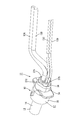
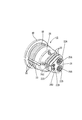
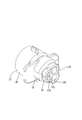
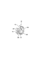
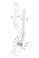
- FIG. 1 The perspective view which shows the sealing structure of the multi-core cable which concerns on Embodiment 1.
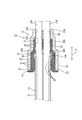
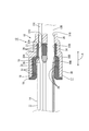
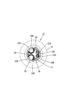
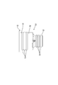
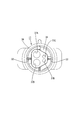
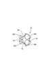
- FIG. Plan view showing the sealing structure of multi-core cable III-III sectional view in FIG. IV-IV sectional view in FIG.
- FIGS. 1 A first embodiment in which the present invention is applied to a seal member 10 will be described with reference to FIGS.
- the present embodiment can be used, for example, for a wire harness for an electric parking brake mounted on a vehicle (not shown).
- the left-right direction in FIG. Further, the right side in FIG. 2 is assumed to be the front in the direction A, and the left side in FIG.
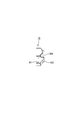
- the multicore cable 11 As shown in FIGS. 1 to 4, the multicore cable 11 according to the present embodiment includes a sheath 14 made of a synthetic resin in which a plurality of electric wires 13A, 13B, 13C, and 13D (four in this embodiment) are insulative. It is an enclosed structure.
- the electric wires 13A, 13B, 13C, and 13D have a configuration in which the outer periphery of a metal core wire (not shown) is covered with a synthetic resin insulating coating (not shown).
- the cross-sectional shape of the multicore cable 11 is circular.
- the four electric wires 13A, 13B, 13C, and 13D include two types of electric wires 13A, 13B, 13C, and 13D having different outer diameter dimensions.
- a first electric wire 13A and a second electric wire 13B connected to a motor for an electric parking brake, a third electric wire 13C for an anti-lock brake system sensor, and a fourth electric wire 13D are included.
- the cross-sectional shapes of the first electric wire 13A, the second electric wire 13B, the third electric wire 13C, and the fourth electric wire 13D are circular.
- the outer diameter of the first electric wire 13A and the second electric wire 13B is set larger than the outer diameter of the third electric wire 13C and the fourth electric wire 13D.
- the outer diameter of the first electric wire 13A and the outer diameter of the second electric wire 13B are set to be the same.
- the outer diameter dimension of the third electric wire 13C and the outer diameter dimension of the fourth electric wire 13D are set to be the same.
- a first electric wire 13A, a second electric wire 13B, a third electric wire 13C, and a fourth electric wire 13D are led out from the end portion 14A of the sheath 14 of the multicore cable 11 and branched.
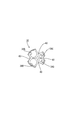
- seal member 10 As shown in FIGS. 1 to 4, in the end portion 14A of the sheath 14 of the multi-core cable 11, there is a region where the first electric wire 13A, the second electric wire 13B, the third electric wire 13C, and the fourth electric wire 13D are branched.
- a seal member 10 is attached.
- the seal member 10 prevents liquid such as water and oil from entering the sheath 14 from the end portion 14A of the sheath 14.
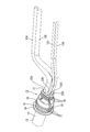
- the seal member 10 is externally fitted to the rubber plug 15 that is externally fitted to the end portion 14 ⁇ / b> A of the sheath 14, a guide member 16 (an example of a rear guide member) that is attached inside the rubber plug 15, and the rubber plug 15.
- a cap 17 (an example of a front guide member).
- a rubber plug 15 is fitted on the end portion 14 ⁇ / b> A of the sheath 14.
- the rubber plug 15 has a sheath outer fitting portion 18 that is fitted on the end portion 14 ⁇ / b> A of the sheath 14.
- the sheath outer fitting portion 18 extends in a direction opposite to the end portion 14A of the sheath 14 (left side in FIG. 3) and is formed in a hood shape that opens in a direction opposite to the end portion 14A of the sheath 14 (left side in FIG. 3). ing.
- the sheath outer fitting portion 18 is formed in a hood shape that extends rearward in the extending direction A and opens rearward in the extending direction A.
- a flange portion 19 that protrudes outward in the radial direction of the sheath outer fitting portion 18 is formed at the end edge portion of the sheath outer fitting portion 18.
- the sheath outer fitting portion 18 is formed in a substantially cylindrical shape in a natural state.
- Sheath side lip 20 As shown in FIGS. 3, 4, and 8, a plurality of sheath side lips 20 projecting inward are annularly formed along the circumferential direction of the sheath outer fitting portion 18 on the inner circumference of the sheath outer fitting portion 18. Is formed.
- the sheath side lip 20 is in close contact with the outer periphery of the sheath 14 in a state where the sheath outer fitting portion 18 is fitted on the end portion 14 ⁇ / b> A of the sheath 14. Thereby, the gap between the rubber plug 15 and the sheath 14 is sealed.
- the rubber plug 15 includes a first electric wire 13 ⁇ / b> A, a second electric wire 13 ⁇ / b> B, a third electric wire 13 ⁇ / b> C, and a fourth electric wire at the end opposite to the sheath outer fitting portion 18.
- An electric wire penetrating portion 21 having a plurality of (four in this embodiment) through holes 22A, 22B, 22C, and 22D through which each of the electric wires 13D passes is provided.
- the plurality of through holes 22A, 22B, 22C, and 22D are penetrated by the first through hole 22A through which the first electric wire 13A passes, the second through hole 22B through which the second electric wire 13B passes, and the third electric wire 13C.
- the first to fourth through holes 22A, 22B, 22C, and 22D are formed to extend in the extending direction A.
- the cross-sectional shape of the wire penetration part 21 is formed in a trapezoidal shape with rounded corners.
- the cross-sectional shape of the wire penetration part 21 is such that the long side 23, the short side 24 parallel to the long side 23 and shorter than the long side 23, and the end of the long side 23 and the end of the short side 24 are connected.
- Two hypotenuses 25 are connected.
- a first through hole 22 ⁇ / b> A and a second through hole 22 ⁇ / b> B are formed side by side along the direction in which the long side 23 extends (vertical direction in FIG. 9) at a position near the long side 23.
- a third through hole 22C and a fourth through hole 22D are formed side by side along the direction in which the short side 24 extends (vertical direction in FIG. 9) at a position near the short side 24. ing.
- the inner diameter of the first through hole 22A is slightly larger than the outer diameter of the first electric wire 13A.
- a first electric wire side lip 26A (an example of an electric wire side lip) that is in close contact with the outer periphery of the first electric wire 13A is provided in the first through hole 22A. It is formed in an annular shape along the circumferential direction.
- the first electric wire side lip 26A is in close contact with the outer periphery of the first electric wire 13A in a state where the first electric wire 13A is penetrated into the first through hole 22A. Thereby, the space between the first electric wire 13A and the rubber plug 15 is sealed.
- the inner diameter dimension of the second through hole 22B is slightly larger than the outer diameter dimension of the second electric wire 13B.
- a second electric wire side lip 26B (an example of an electric wire side lip) that is in close contact with the outer periphery of the second electric wire 13B is provided in the second through hole 22B. It is formed in an annular shape along the circumferential direction.
- the 2nd electric wire side lip 26B is closely_contact
- the inner diameter dimension of the third through hole 22C is formed to be slightly larger than the outer diameter dimension of the third electric wire 13C.
- a third electric wire side lip 26C (an example of the electric wire side lip) that is in close contact with the outer periphery of the third electric wire 13C is provided. It is formed in an annular shape along the circumferential direction.
- the third electric wire side lip 26C comes into close contact with the outer periphery of the third electric wire 13C in a state where the third electric wire 13C is penetrated into the third through hole 22C. Thereby, the space between the third electric wire 13C and the rubber plug 15 is sealed.
- the inner diameter dimension of the fourth through hole 22D is formed to be slightly larger than the outer diameter dimension of the fourth electric wire 13D.
- a fourth electric wire side lip 26D (an example of an electric wire side lip) that is in close contact with the outer periphery of the fourth electric wire 13D is provided in the fourth through hole 22D. It is formed in an annular shape along the circumferential direction.
- the fourth electric wire side lip 26D is in close contact with the outer periphery of the fourth electric wire 13D in a state in which the fourth electric wire 13D is passed through the fourth through hole 22D. Thereby, the space between the fourth electric wire 13D and the rubber plug 15 is sealed.
- the rubber plug 15 includes the first electric wire 13 ⁇ / b> A, the first electric wire 13 ⁇ / b> A, and the first electric wire 13 ⁇ / b> A at the position inside the sheath outer fitting portion 18 and between the sheath side lip 20 and the electric wire penetration portion 21.
- a guide member 16 having a plurality of (four in this embodiment) guide holes 38A, 38B, 38C, 38D (an example of guide holes) through which the two electric wires 13B, the third electric wires 13C, and the fourth electric wires 13D are inserted, respectively.
- a holding portion 28 to be held is formed.
- Cap 17 As shown in FIGS. 3 and 4, a synthetic resin cap 17 is fitted on the rubber plug 15.
- the cap 17 is externally fitted to the rubber plug 15 from the end (the right side in FIG. 3) from which the first electric wire 13A, the second electric wire 13B, the third electric wire 13C, and the fourth electric wire 13D are led out from the end portion 14A of the sheath 14.
- the cap 17 is externally fitted to the rubber plug 15 from the front in the extending direction A.
- the cap 17 is opened to the sheath 14 side from the side where the first electric wire 13A, the second electric wire 13B, the third electric wire 13C, and the fourth electric wire 13D are led out (left side in FIG. 3). In other words, the cap 17 is opened rearward in the extending direction A. The opening edge of the cap 17 is in contact with the flange portion 19 of the rubber plug 15 from the front in the extending direction A.
- the cap 17 is formed with a large-diameter portion 30 that is fitted on the sheath outer fitting portion 18 of the rubber plug 15 at a position on the opening edge side (left side in FIG. 3) of the cap 17.
- the cross-sectional shape of the large diameter portion 30 is formed in a circular shape following the outer shape of the sheath outer fitting portion 18.
- the inner periphery of the large-diameter portion 30 is in close contact with a plurality of (three in this embodiment) large-diameter portion side lips 31 formed on the outer periphery of the sheath outer fitting portion 18.
- the large-diameter portion lip 31 protrudes outward on the outer peripheral surface of the sheath outer fitting portion 18 and is formed along the circumferential direction of the sheath outer fitting portion 18. .
- the large-diameter portion lip 31 and the inner periphery of the large-diameter portion 30 of the cap 17 are in close contact, the space between the large-diameter portion 30 of the cap 17 and the sheath outer fitting portion 18 of the rubber plug 15 is sealed. .
- a plurality of (two in this embodiment) cap locking portions in the shape of ribs extending along the opening direction of the cap 17 are provided in the large diameter portion 30 of the cap 17. 32 is formed.
- the two cap locking portions 32 are formed at positions facing each other on the inner periphery of the large-diameter portion 30.
- cap engaging portions 32 are inserted into the outer periphery of the sheath outer fitting portion 18 and the holding portion 28 of the rubber plug 15.
- the cap locked portion 33 is formed in a groove shape along the extending direction of the sheath outer fitting portion 18.
- Each of the two cap locking portions 33 is formed at a position corresponding to each of the two cap locking portions 32 formed in the large diameter portion 30.
- the large-diameter portion 30 is connected to the sheath external fitting portion 18 of the rubber plug 15 while the large-diameter portion 30 of the cap 17 is externally fitted to the sheath external fitting portion 18.
- the fitting portion 18 is pressed inward in the radial direction.
- the sheath outer fitting portion 18 is pressed against the outer periphery of the sheath 14 from the outside.
- the sheath-side lip 20 of the sheath outer fitting portion 18 is securely brought into close contact with the outer periphery of the sheath 14.
- the wire penetration part 21 of the rubber plug 15 is located inside the cap 17 at a position opposite to the opening direction of the cap 17 (right side in FIG. 3) with respect to the large diameter part 30.
- a small-diameter portion 34 that is externally fitted is formed.
- the outer diameter dimension of the small diameter part 34 is set smaller than the outer diameter dimension of the large diameter part 30.
- the cross-sectional shape of the small diameter portion 34 is formed in a trapezoidal shape with rounded corners following the outer shape of the wire penetration portion 21.
- the inner periphery of the small diameter portion 34 comes into close contact with a plurality of (three in this embodiment) small diameter portion lips 35 formed on the outer periphery of the wire penetration portion 21. Yes.
- the small-diameter portion lip 35 protrudes outward on the outer peripheral surface of the wire penetration portion 21 and is formed along the circumferential direction of the wire penetration portion 21.
- the small diameter portion 34 of the cap 17 in a state where the small diameter portion 34 of the cap 17 is externally fitted to the electric wire penetration portion 21 of the rubber plug 15, the small diameter portion 34 changes the electric wire penetration portion 21 and the diameter of the electric wire penetration portion 21. It pushes inward in the direction. Thereby, the electric wire penetration part 21 is compressed from the outside. As a result, the first to fourth electric wire side lips 26D formed on the inner periphery of the first to fourth through holes 22D are securely attached to the outer periphery of each of the first to fourth electric wires 13A, 13B, 13C, 13D. It has come to be.
- the cap 17 has a back wall 36 at a position opposite to the opening direction of the cap 17.
- the back wall 36 is disposed at a position in front of the extending direction A with respect to the wire penetration part 21 of the rubber plug 15.
- the first lead-out holes 37 ⁇ / b> A guides through which the first electric wires 13 ⁇ / b> A, the second electric wires 13 ⁇ / b> B, the third electric wires 13 ⁇ / b> C, and the fourth electric wires 13 ⁇ / b> D are led out from the cap 17.
- the first electric wire 13A is inserted into the first outlet hole 37A
- the second electric wire 13B is inserted into the second outlet hole 37B
- the third electric wire 13C is inserted into the third outlet hole 37C
- the fourth electric wire 13D is inserted into the fourth electric wire 37D.
- the cap locking portion 32 formed in the large-diameter portion 30 of the cap 17 and the cap locked portion 33 formed in the sheath outer fitting portion 18 of the rubber plug 15 are locked.
- the rubber plug 15 is positioned relative to the cap 17.
- each of the first to fourth through holes 22A, 22B, 22C, 22D formed in the rubber plug 15 and the first to fourth lead-outs formed in the cap 17 are obtained.
- the holes 37A, 37B, 37C and 37D are aligned with each other.
- first through hole 22A and the first outlet hole 37A are aligned
- second through hole 22B and the second outlet hole 37B are aligned
- third through hole 22C and the third outlet hole 37C are aligned
- fourth through hole 22D and the fourth lead-out hole 37D are aligned with each other.
- the guide member 16 is made of synthetic resin, and includes a first guide hole 38A through which the first electric wire 13A is inserted, and a second guide hole 38B through which the second electric wire 13B is inserted.
- the third guide hole 38C through which the third electric wire 13C is inserted and the fourth guide hole 38D through which the fourth electric wire 13D is inserted are penetrated.
- the guide member 16 is arranged at a position rearward in the extending direction A with respect to the wire penetration portion 21 in a state where the guide member 16 is held by the holding portion 28 of the rubber plug 15.
- a plurality (four in this embodiment) of guide member locked portions 39 projecting inward are formed on the inner periphery of the holding portion 28 of the rubber plug 15. Yes.
- a plurality (four in this embodiment) of guide member locking portions 40 into which each of the four guide member locked portions 39 is fitted are recessed from the outer periphery of the guide member 16. Is formed.
- Each of the four guide member locking portions 40 formed on the guide member 16 is formed at a position corresponding to each of the four guide member locked portions 39 formed on the rubber plug 15.
- Each of the four guide member locked portions 39 formed on the holding portion 28 of the rubber plug 15 engages with each of the four guide member locking portions 40 formed on the guide member 16.
- the guide member 16 is held in a state in which rotation of the guide member 16 in the circumferential direction of the guide member 16 with respect to the rubber plug 15 is suppressed. Thereby, relative positioning of the rubber stopper 15 and the guide member 16 is made.
- the first to fourth through holes 22A, 22B, 22C, 22D of the rubber plug 15 and the first to fourth guide holes 38A, 38B, 38C and 38D are matched with each other.
- first through hole 22A and the first guide hole 38A are aligned
- second through hole 22B and the second guide hole 38B are aligned
- third through hole 22C and the third guide hole 38C are aligned
- fourth through hole 22D and the fourth guide hole 38D are aligned with each other.
- the sheath 14 of the multicore cable 11 is peeled off by a known method.
- the first to fourth electric wires 13A, 13B, 13C, and 13D are led out from the end portion 14A of the sheath 14.
- the first to fourth electric wires 13A, 13B, 13C, and 13D are inserted into the first to fourth guide holes 38A, 38B, 38C, and 38D of the guide member 16, respectively.
- the fourth electric wire 13D is inserted through 38D.
- the first to fourth electric wires 13A, 13B, 13C, and 13D are inserted into the first to fourth through holes 22A, 22B, 22C, and 22D of the rubber plug 15, respectively.
- the first electric wire 13A is inserted through the first through hole 22A
- the second electric wire 13B is inserted through the second through hole 22B
- the third electric wire 13C is inserted through the third through hole 22C
- the fourth through hole is inserted.
- the fourth electric wire 13D is inserted through 22D.
- the rubber stopper 15 is moved to the position of the guide member 16.
- the first to fourth through holes 22A, 22B, 22C, 22D of the rubber plug 15 and the first to fourth guide holes 38A, 38B, 38C, 38D of the guide member 16 are aligned with each other.
- the relative positions of the rubber plug 15 and the guide member 16 are adjusted so as to be arranged.
- the guide member 16 side locking portion of the rubber plug 15 and the guide member 16 side locked portion of the guide member 16 are locked.
- each of the first to fourth through holes 22A, 22B, 22C, and 22D of the rubber plug 15 is aligned with each of the first to fourth guide holes 38A, 38B, 38C, and 38D of the guide member 16.
- the guide member 16 is held by the holding portion 28 of the rubber plug 15.
- the rubber plug 15 is moved to the end portion 14 ⁇ / b> A of the sheath 14, and the sheath external fitting portion 18 of the rubber plug 15 is externally fitted to the end portion 14 ⁇ / b> A of the sheath 14.
- the first to fourth electric wires 13A, 13B, 13C, and 13D are inserted into the first to fourth lead-out holes 37A, 37B, 37C, and 37D of the cap 17, respectively.
- the first electric wire 13A is inserted through the first outlet hole 37A
- the second electric wire 13B is inserted through the second outlet hole 37B
- the third electric wire 13C is inserted through the third outlet hole 37C
- the fourth outlet hole is inserted.
- the fourth electric wire 13D is inserted through 37D.
- the cap 17 is moved to the position of the rubber plug 15 fitted on the end 14 ⁇ / b> A of the sheath 14.
- the first to fourth through holes 22A, 22B, 22C, 22D of the rubber plug 15 and the first to fourth outlet holes 37A, 37B, 37C, 37D of the cap 17 are aligned with each other.
- the relative positions of the rubber plug 15 and the cap 17 are adjusted so that In the above state, the rubber plug 15 side locking portion of the cap 17 and the rubber plug 15 side locked portion of the rubber plug 15 are locked.
- the first to fourth through holes 22A, 22B, 22C, 22D of the rubber plug 15 and the first to fourth outlet holes 37A, 37B, 37C, 37D of the cap 17 are aligned with each other.
- the cap 17 is fitted on the rubber plug 15. Thereafter, the cap 17 is pushed in until it comes into contact with the flange portion 19 of the rubber plug 15. Thereby, the seal member 10 according to the present embodiment is completed, and the seal structure 12 of the multicore cable 11 is completed (see FIG. 1).
- each of the plurality of first to fourth electric wires 13A, 13B, 13C, 13D is inserted into the first to fourth outlet holes 37A, 37B, 37C, 37D of the cap 17, and the guide
- each of the plurality of first electric wires 13A, 13B, 13C, 13D has the plurality of first to fourth through holes 22A, Each of 22B, 22C, and 22D is reliably guided.
- each of the plurality of first to fourth electric wires 13A, 13B, 13C, and 13D is reliably sealed with the inner periphery of each of the plurality of first to fourth through holes 22A, 22B, 22C, and 22D. Is done. As a result, it is possible to suppress deterioration in the sealing performance between the plurality of first to fourth electric wires 13A, 13B, 13C, 13C and the rubber plug 15.
- the guide member 16 has the guide member locking portion 40 that locks with the rubber plug 15, and the rubber plug 15 engages with the guide member locking portion 40.
- a plurality of first through fourth through holes 22A, 22B, and 22C of the rubber plug 15 are provided by having a locking portion 39 and engaging the guide member locking portion 40 and the guide member locked portion 39.
- 22D and the first to fourth guide holes 38A, 38B, 38C, 38D of the guide member 16 are aligned with each other so that the relative arrangement of the rubber plug 15 and the guide member 16 is maintained. ing.
- each of the plurality of first to fourth guide holes 38A, 38B, 38C, and 38D is securely held at a position that aligns with each of the plurality of first to fourth through holes 22A, 22B, 22C, and 22D. be able to. As a result, it is possible to reliably suppress a decrease in the sealing performance between the plurality of first to fourth electric wires 13A, 13B, 13C, 13D and the rubber plug 15.
- the cap 17 has the cap locking portion 32 that locks with the rubber plug 15, and the rubber plug 15 engages with the cap locking portion 32.
- the cap locking portion 32 and the cap locked portion 33 are engaged, the plurality of first to fourth through holes 22A, 22B, 22C, 22D of the rubber plug 15 and the cap 17 are The relative arrangement of the rubber plug 15 and the cap 17 is maintained at a position where the plurality of first to fourth lead-out holes 37A, 37B, 37C, and 37D are aligned.
- each of the plurality of first to fourth lead-out holes 37A, 37B, 37C, and 37D is securely held at a position that aligns with each of the plurality of first to fourth through holes 22A, 22B, 22C, and 22D. be able to. Thereby, it can suppress reliably that the sealing performance between several electric wire 13A, 13B, 13C, 13D and the rubber stopper 15 falls.
- the cap 17 is arranged at a position in front of the wire penetration part 21 in the extending direction A, and the guide member 16 is at a position behind the wire penetration part 21 in the extension direction A. It is arranged.
- each of the plurality of first to fourth electric wires 13A, 13B, 13C, and 13D is connected to the plurality of first to fourth through holes 22A, 22B, 22C, and 22D at a position in front of the wire penetration portion 21 in the extending direction A.
- Each of the plurality of first to fourth electric wires 13A, 13B, 13C, 13D can be guided through the plurality of first to fourth penetrations at the position behind the wire penetration portion 21 in the extending direction A.
- Each of the holes 22A, 22B, 22C, and 22D can be guided. As a result, it is possible to reliably suppress a decrease in the sealing performance between the plurality of first to fourth electric wires 13A, 13B, 13C, 13D and the rubber plug 15.
- each of the plurality of first to fourth electric wires 13A, 13B, 13C, and 13D is provided on the inner periphery of each of the plurality of first to fourth through holes 22A, 22B, 22C, and 22D.
- First to fourth electric wire side lips 26A, 26B, 26C, and 26D are formed to be in close contact with the outer periphery of the first electric wire. Accordingly, the first to fourth electric wire side lips 26A, 26B, 26C, and 26D are in close contact with the outer circumferences of the first to fourth electric wires 13A, 13B, 13C, and 13D. It can suppress reliably that the sealing performance between 13A, 13B, 13C, 13D and the rubber stopper 15 falls.
- the seal member has a positioning member that is a separate member from the guide member and the rubber plug, the positioning member and the guide member are relatively positioned, and the positioning member and the rubber plug are relatively positioned. Thereby, it is good also as a structure positioned in the position where a some through-hole and a some guide hole align.
- the seal member 10 is configured to include both the cap 17 and the guide member 16, but the present invention is not limited thereto, and the seal member 10 may include only the cap 17, and the guide It is good also as a structure which has only the member 16.
- FIG. 1 the seal member 10 is configured to include both the cap 17 and the guide member 16, but the present invention is not limited thereto, and the seal member 10 may include only the cap 17, and the guide It is good also as a structure which has only the member 16.
- the number of electric wires arranged in the multicore cable 11 may be 2 to 3, or 5 or more.
- the plurality of electric wires are configured to include electric wires having two types of outer diameters, but are not limited thereto, and may be configured to include electric wires having three or more types of outer diameters.
- the outer diameters of the plurality of wires may all be the same.
- the wire may be a shielded wire.
- the electric wire may be a stranded wire provided with a core wire in which a plurality of fine metal wires are twisted together, or may be a so-called single core wire having a metal rod as a core wire.
- arbitrary electric wires can be appropriately selected as necessary.
- the multi-core cable 11 may be a so-called cabtyre cable, or may be a multi-core shielded cable in which the outer periphery of a plurality of wires is surrounded by a shield layer.
- any multi-core cable 11 can be appropriately selected as necessary.
- any liquid such as water, oil, organic solvent, or the like can be sealed as necessary.
- the seal member 10 is assembled by assembling the guide member 16, the rubber plug 15, and the cap 17 in this order to the multicore cable 11 with the sheath 14 peeled off, and the multicore cable is assembled.
- the present invention is not limited to this, and by inserting a plurality of electric wires of the multi-core cable 11 with the sheath 14 peeled off into a pre-assembled seal member 10, a multi-core structure is formed.
- the cable 11 and the seal member 10 may be assembled.
Landscapes
- Engineering & Computer Science (AREA)
- Architecture (AREA)
- Civil Engineering (AREA)
- Structural Engineering (AREA)
- Connector Housings Or Holding Contact Members (AREA)
- Installation Of Indoor Wiring (AREA)
- Gasket Seals (AREA)
- Insulated Conductors (AREA)
Abstract
L'élément de scellement (10) de l'invention est équipé : d'un bouchon de caoutchouc (15) qui est à son tour équipé d'une partie pénétration de conducteur (21) possédant des premier à quatrième orifices de pénétration (22A, 22B, 22C, 22D) dans lesquels pénètrent individuellement des premier à quatrième conducteurs (13A, 13B, 13C, 13D) ; et d'un élément guidage (16) qui est placé à l'arrière de la partie pénétration de conducteur (21) dans une direction de prolongement (A) dans laquelle les premier à quatrième conducteurs (13A, 13B, 13C, 13D) pénètrent dans les premier à quatrième orifices de pénétration (22A, 22B, 22C, 22D), dans lequel les premier à quatrième conducteurs (13A, 13B, 13C, 13D) sont insérés individuellement, et qui possède des premier à quatrième orifice de guidage (38A, 38B, 38C, 38D) se combinant aux premier à quatrième orifices de pénétration (22A, 22B, 22C, 22D) du bouchon de caoutchouc (15).
Priority Applications (3)
| Application Number | Priority Date | Filing Date | Title |
|---|---|---|---|
| CN201580033883.9A CN106463935B (zh) | 2014-06-26 | 2015-06-23 | 密封部件 |
| US15/316,340 US10236671B2 (en) | 2014-06-26 | 2015-06-23 | Sealing member |
| EP15812206.9A EP3148025B1 (fr) | 2014-06-26 | 2015-06-23 | Élément de scellement |
Applications Claiming Priority (2)
| Application Number | Priority Date | Filing Date | Title |
|---|---|---|---|
| JP2014131701A JP5862710B2 (ja) | 2014-06-26 | 2014-06-26 | シール部材 |
| JP2014-131701 | 2014-06-26 |
Publications (1)
| Publication Number | Publication Date |
|---|---|
| WO2015199056A1 true WO2015199056A1 (fr) | 2015-12-30 |
Family
ID=54938138
Family Applications (1)
| Application Number | Title | Priority Date | Filing Date |
|---|---|---|---|
| PCT/JP2015/067970 WO2015199056A1 (fr) | 2014-06-26 | 2015-06-23 | Élément de scellement |
Country Status (5)
| Country | Link |
|---|---|
| US (1) | US10236671B2 (fr) |
| EP (1) | EP3148025B1 (fr) |
| JP (1) | JP5862710B2 (fr) |
| CN (1) | CN106463935B (fr) |
| WO (1) | WO2015199056A1 (fr) |
Families Citing this family (9)
| Publication number | Priority date | Publication date | Assignee | Title |
|---|---|---|---|---|
| JP6439672B2 (ja) * | 2015-12-22 | 2018-12-19 | 株式会社オートネットワーク技術研究所 | ケーブルの保持構造 |
| DE102017121459B4 (de) * | 2017-09-15 | 2024-03-14 | Auto-Kabel Management Gmbh | Kabelabdichtung sowie Anordnung mit einem Gehäuse |
| JP6924387B2 (ja) * | 2018-03-15 | 2021-08-25 | 株式会社オートネットワーク技術研究所 | 電線の保持構造 |
| JP2019178696A (ja) * | 2018-03-30 | 2019-10-17 | 矢崎総業株式会社 | Oリング、oリング係止構造、端子台及び車載機器 |
| EP3864729A1 (fr) * | 2018-10-12 | 2021-08-18 | Eaton Intelligent Power Limited | Presse-étoupe de câble comprenant un élément formant barrage interne |
| JP7298502B2 (ja) * | 2020-02-18 | 2023-06-27 | 株式会社プロテリアル | 複合ハーネス |
| DE102020208964A1 (de) * | 2020-07-17 | 2022-01-20 | Conti Tech Techno-Chemie Gmbh | Ladeleitung für ein Elektrofahrzeug |
| JP7476752B2 (ja) * | 2020-10-02 | 2024-05-01 | 住友電装株式会社 | コネクタ |
| JP2022183830A (ja) * | 2021-05-31 | 2022-12-13 | 日本電産コパル電子株式会社 | 封止部材とそれを用いた封止構造 |
Citations (2)
| Publication number | Priority date | Publication date | Assignee | Title |
|---|---|---|---|---|
| JPH11329567A (ja) * | 1998-05-11 | 1999-11-30 | Sumitomo Wiring Syst Ltd | 防水コネクタ |
| JP2013097898A (ja) * | 2011-10-28 | 2013-05-20 | Sumitomo Wiring Syst Ltd | シール部材 |
Family Cites Families (14)
| Publication number | Priority date | Publication date | Assignee | Title |
|---|---|---|---|---|
| DE3417811C1 (de) * | 1984-05-14 | 1985-10-17 | kabelmetal electro GmbH, 3000 Hannover | Verfahren zum Anbringen eines Kupplungsteils am Ende einer elektrischen Leitung |
| EP0580130A1 (fr) | 1992-07-21 | 1994-01-26 | Ichikoh Industries Limited | Traversée pour conducteurs électriques |
| JP3121128B2 (ja) | 1992-07-21 | 2000-12-25 | 市光工業株式会社 | コード用グロメット |
| JPH0822862A (ja) * | 1994-07-07 | 1996-01-23 | Yazaki Corp | 防水ゴム栓 |
| JP2000348815A (ja) | 1999-06-03 | 2000-12-15 | Yazaki Corp | 防水コネクタ及び該防水コネクタの組付方法 |
| CN2615930Y (zh) | 2003-03-13 | 2004-05-12 | 许玉玲 | 可防止电缆潜动的管路封塞 |
| JP5380751B2 (ja) * | 2009-12-24 | 2014-01-08 | 日立金属株式会社 | ワイヤハーネス及びその製造方法 |
| AU2011303943B2 (en) * | 2010-09-17 | 2014-08-28 | Roxtec Ab | Modular connector for cables or pipes and system comprising such modular connector |
| JP5738604B2 (ja) * | 2011-01-12 | 2015-06-24 | 矢崎総業株式会社 | 電線保持・防水構造、及びledユニット |
| JP2012243546A (ja) * | 2011-05-19 | 2012-12-10 | Yazaki Corp | 防水コネクタ |
| JP5790492B2 (ja) * | 2011-12-28 | 2015-10-07 | 住友電装株式会社 | 電線固定部材 |
| US20140045357A1 (en) * | 2012-08-13 | 2014-02-13 | John Mezzalingua Associates, LLC | Integrated Retainer and Seal for Coaxial Cable Connector |
| CN203218581U (zh) * | 2013-04-10 | 2013-09-25 | 镇江惠通元二接插件有限公司 | 水密连接器 |
| CN203589673U (zh) * | 2013-12-06 | 2014-05-07 | 贵州航天凯山石油仪器有限公司 | 一种井下仪器连接电缆的密封结构 |
-
2014
- 2014-06-26 JP JP2014131701A patent/JP5862710B2/ja active Active
-
2015
- 2015-06-23 CN CN201580033883.9A patent/CN106463935B/zh active Active
- 2015-06-23 EP EP15812206.9A patent/EP3148025B1/fr active Active
- 2015-06-23 WO PCT/JP2015/067970 patent/WO2015199056A1/fr active Application Filing
- 2015-06-23 US US15/316,340 patent/US10236671B2/en active Active
Patent Citations (2)
| Publication number | Priority date | Publication date | Assignee | Title |
|---|---|---|---|---|
| JPH11329567A (ja) * | 1998-05-11 | 1999-11-30 | Sumitomo Wiring Syst Ltd | 防水コネクタ |
| JP2013097898A (ja) * | 2011-10-28 | 2013-05-20 | Sumitomo Wiring Syst Ltd | シール部材 |
Also Published As
| Publication number | Publication date |
|---|---|
| EP3148025B1 (fr) | 2019-07-31 |
| CN106463935B (zh) | 2019-06-25 |
| US10236671B2 (en) | 2019-03-19 |
| EP3148025A4 (fr) | 2018-02-14 |
| JP5862710B2 (ja) | 2016-02-16 |
| EP3148025A1 (fr) | 2017-03-29 |
| CN106463935A (zh) | 2017-02-22 |
| US20180109097A1 (en) | 2018-04-19 |
| JP2016010304A (ja) | 2016-01-18 |
Similar Documents
| Publication | Publication Date | Title |
|---|---|---|
| JP5862710B2 (ja) | シール部材 | |
| JP5862709B2 (ja) | シール部材、及び多芯ケーブルのシール構造 | |
| US9558866B2 (en) | Wire harness | |
| WO2017104392A1 (fr) | Structure d'étanchéité de câble multicœur | |
| CN108292834B (zh) | 电缆的保持结构 | |
| WO2016104242A1 (fr) | Structure d'étanchéité pour câble multiconducteur, et élément d'étanchéité | |
| WO2016104241A1 (fr) | Structure de joint d'étanchéité pour câble multiconducteur | |
| JP6376107B2 (ja) | シール部材、及び多芯ケーブルのシール構造 | |
| WO2017082376A1 (fr) | Structure d'étanchéité pour câble, et organe d'étanchéité | |
| WO2018168394A1 (fr) | Structure étanche à l'eau pour connecteur | |
| JP2011222445A (ja) | コネクタ | |
| JP2006271119A (ja) | グロメット |
Legal Events
| Date | Code | Title | Description |
|---|---|---|---|
| 121 | Ep: the epo has been informed by wipo that ep was designated in this application |
Ref document number: 15812206 Country of ref document: EP Kind code of ref document: A1 |
|
| WWE | Wipo information: entry into national phase |
Ref document number: 15316340 Country of ref document: US |
|
| REEP | Request for entry into the european phase |
Ref document number: 2015812206 Country of ref document: EP |
|
| WWE | Wipo information: entry into national phase |
Ref document number: 2015812206 Country of ref document: EP |
|
| NENP | Non-entry into the national phase |
Ref country code: DE |