EP0580130A1 - Traversée pour conducteurs électriques - Google Patents
Traversée pour conducteurs électriques Download PDFInfo
- Publication number
- EP0580130A1 EP0580130A1 EP93111613A EP93111613A EP0580130A1 EP 0580130 A1 EP0580130 A1 EP 0580130A1 EP 93111613 A EP93111613 A EP 93111613A EP 93111613 A EP93111613 A EP 93111613A EP 0580130 A1 EP0580130 A1 EP 0580130A1
- Authority
- EP
- European Patent Office
- Prior art keywords
- lead
- wall
- outer member
- opening
- wire
- Prior art date
- Legal status (The legal status is an assumption and is not a legal conclusion. Google has not performed a legal analysis and makes no representation as to the accuracy of the status listed.)
- Withdrawn
Links
Images


Classifications
-
- F—MECHANICAL ENGINEERING; LIGHTING; HEATING; WEAPONS; BLASTING
- F16—ENGINEERING ELEMENTS AND UNITS; GENERAL MEASURES FOR PRODUCING AND MAINTAINING EFFECTIVE FUNCTIONING OF MACHINES OR INSTALLATIONS; THERMAL INSULATION IN GENERAL
- F16L—PIPES; JOINTS OR FITTINGS FOR PIPES; SUPPORTS FOR PIPES, CABLES OR PROTECTIVE TUBING; MEANS FOR THERMAL INSULATION IN GENERAL
- F16L5/00—Devices for use where pipes, cables or protective tubing pass through walls or partitions
- F16L5/02—Sealing
- F16L5/10—Sealing by using sealing rings or sleeves only
-
- B—PERFORMING OPERATIONS; TRANSPORTING
- B60—VEHICLES IN GENERAL
- B60R—VEHICLES, VEHICLE FITTINGS, OR VEHICLE PARTS, NOT OTHERWISE PROVIDED FOR
- B60R16/00—Electric or fluid circuits specially adapted for vehicles and not otherwise provided for; Arrangement of elements of electric or fluid circuits specially adapted for vehicles and not otherwise provided for
- B60R16/02—Electric or fluid circuits specially adapted for vehicles and not otherwise provided for; Arrangement of elements of electric or fluid circuits specially adapted for vehicles and not otherwise provided for electric constitutive elements
- B60R16/0207—Wire harnesses
- B60R16/0215—Protecting, fastening and routing means therefor
- B60R16/0222—Grommets
-
- F—MECHANICAL ENGINEERING; LIGHTING; HEATING; WEAPONS; BLASTING
- F16—ENGINEERING ELEMENTS AND UNITS; GENERAL MEASURES FOR PRODUCING AND MAINTAINING EFFECTIVE FUNCTIONING OF MACHINES OR INSTALLATIONS; THERMAL INSULATION IN GENERAL
- F16L—PIPES; JOINTS OR FITTINGS FOR PIPES; SUPPORTS FOR PIPES, CABLES OR PROTECTIVE TUBING; MEANS FOR THERMAL INSULATION IN GENERAL
- F16L5/00—Devices for use where pipes, cables or protective tubing pass through walls or partitions
- F16L5/02—Sealing
- F16L5/025—Sealing the pipe being movable
-
- F—MECHANICAL ENGINEERING; LIGHTING; HEATING; WEAPONS; BLASTING
- F16—ENGINEERING ELEMENTS AND UNITS; GENERAL MEASURES FOR PRODUCING AND MAINTAINING EFFECTIVE FUNCTIONING OF MACHINES OR INSTALLATIONS; THERMAL INSULATION IN GENERAL
- F16L—PIPES; JOINTS OR FITTINGS FOR PIPES; SUPPORTS FOR PIPES, CABLES OR PROTECTIVE TUBING; MEANS FOR THERMAL INSULATION IN GENERAL
- F16L5/00—Devices for use where pipes, cables or protective tubing pass through walls or partitions
- F16L5/02—Sealing
- F16L5/027—Sealing by means of a joint of the quick-acting type
-
- F—MECHANICAL ENGINEERING; LIGHTING; HEATING; WEAPONS; BLASTING
- F16—ENGINEERING ELEMENTS AND UNITS; GENERAL MEASURES FOR PRODUCING AND MAINTAINING EFFECTIVE FUNCTIONING OF MACHINES OR INSTALLATIONS; THERMAL INSULATION IN GENERAL
- F16L—PIPES; JOINTS OR FITTINGS FOR PIPES; SUPPORTS FOR PIPES, CABLES OR PROTECTIVE TUBING; MEANS FOR THERMAL INSULATION IN GENERAL
- F16L5/00—Devices for use where pipes, cables or protective tubing pass through walls or partitions
- F16L5/02—Sealing
- F16L5/14—Sealing for double-walled or multi-channel pipes
-
- H—ELECTRICITY
- H02—GENERATION; CONVERSION OR DISTRIBUTION OF ELECTRIC POWER
- H02G—INSTALLATION OF ELECTRIC CABLES OR LINES, OR OF COMBINED OPTICAL AND ELECTRIC CABLES OR LINES
- H02G3/00—Installations of electric cables or lines or protective tubing therefor in or on buildings, equivalent structures or vehicles
- H02G3/22—Installations of cables or lines through walls, floors or ceilings, e.g. into buildings
Definitions
- the present invention relates to a rubber- or rubber/synthetic resin-grommet for watertight passage of at least a lead wire through an opening formed in a wall from one side of the wall to the other side and which does not need any taping of the lead wire to the wall for sealing a space or clearance between the opening and the lead wire passed through the opening.
- the lead-wire grommet according to the present invention is destined for use to water-tightly pass a lead wire through an opening formed in a wall that a water is blocked from flowing through between the lead-wire grommet and the edge of the opening in the wall and between the lead-wire grommet and the lead wire from one side of the wall to the other side which must be kept watertight.
- This lead-wire grommet is used, for example, for water-tightly leading out lead wires connected to an electric apparatus which has to be kept off water through an opening formed in a container housing the electric apparatus to outside the container to thereby prevent a water from entering into the container, or for water-tightly passing lead wires connected between a rear combination lamp and a battery on a car through an opening formed in a wall or car body defining a trunk room of the car in order to prevent water from entering into the trunk room.
- the present invention relates to a highly watertight lead-wire grommet.
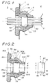
- FIG. 2 showing a prior art in the publication of the U.S. Pat. No. 4,845,600.
- This example consists of two rubber bushings 15 and 16 each having an insertion hole through which lead wires 10 are passed water-tightly as tightly fitted.
- These rubber bushings 15 and 16 are water-tightly fitted in through-holes, respectively, formed in partition walls 4 and 14, respectively to prevent water from entering into the inner chamber of a spoiler 2 and the lamp house of a high-mount stop lamp 3.
- the rubber grommet (rubber bushing) has slits formed radially from the outer circumference thereof to the insertion holes.
- the rubber grommet is elastically deformed at the slits so that the lead wires can be easily set in the insertion holes.
- the rubber grommet restores its initial shape due to their elasticity.
- the present invention has a primary object to provide a highly watertight lead-wire grommet.
- the grommet according to the present invention has formed in a rubber-made inner member thereof at least an insertion hole through which a lead wire is passed as tightly fitted, and a slit through which the lead wire is inserted for setting in the insertion hole.
- the grommet has also formed in a rubber-made outer member thereof a retention hole in which the inner member is held as tightly fitted, and an engagement groove at which the outer member is tightly fitted on the edge of an opening formed in a support wall.
- the inner member in which a lead wire is water-tightly set in the insertion hole thereof is held as tightly fitted in the retention hole in the outer member, the tight fitting will cause the walls of the slits in the inner member to closely fit each other, resulting in a higher watertightness.
- the present invention has another object to provide a lead-wire grommet in which the inner member can be positively blocked from slipping out of the outer member.
- a lead-wire grommet constructed as follows. Namely, a rubber-made inner member having lead wires passed through insertion holes thereof as tightly fitted is retained in a resin-made cap as tightly fitted, the resin-made cap and a resin-made ring are held in a retention hole formed in a rubber-made outer member and fitted in each other, and the inner member is pressed between the cap and ring from opposite sides in the direction of lead-wire insertion.
- the present invention provides a lead-wire grommet of which the inner member can be positively blocked from coming out of the outer member.
- Figs. 1 to 7 show together a first embodiment of the lead-wire grommet according to the present invention, of which:
- Figs. 1 to 7 show together the first embodiment of the lead-wire grommet according to the present invention.
- This embodiment will be explained concerning its use to water-tightly fix lead wires connecting, for example, a rear combination lamp of a car and a power source to each other through a wall of the car body.
- reference numeral 1 denotes a wall, a portion of the car body.
- the wall 1 defines a trunk room I of the car to the right thereof as shown in Fig. 1.
- a convexity O where the rear combination lamp is disposed.
- the lead-wire grommet according to the present invention is used to prevent water from coming from the convexity O where the rear combination lamp at the left of the wall 1 is disposed into the trunk room I of the car at the right side of the wall 1.
- a circular opening 10 is formed in the wall 1 and the edge of the opening 10 is bent at a right angle into the trunk room I to form a short circular flange 11.
- reference numeral 3 denotes lead wires which connect a vehicle lamp (not shown) such as rear combination lamp and a power source (not shown) to each other.
- the lead wires 3 are an ordinary lead wire consisting of a conductor and a cylindrical insulation tube sheathing the conductor as shown in Fig. 1.
- Reference numeral 4 denotes an inner member.
- the inner member 4 is made of a synthetic rubber such as EPDM (ethylene propylene rubber) and has the form of a short cylinder. As shown in Fig. 2, the inner member 4 is so rounded at a corner 42 defined by one end 43 (at the right side of the inner member 4 in Fig. 2) and outer circumference 44 as to easily be insertable into a through-hole 51 formed in an outer member 5 which will be described later.
- EPDM ethylene propylene rubber
- the inner member 4 has at least an insertion hole 40 formed therein as regularly spaced and through which the lead wire 3 is to be passed, and also has slits 41 cut therein radially from the outer circumference thereof to the lead-wire insertion hole 40 and through which the lead wire 3 is to be placed into the insertion hole 40.
- the inside diameter of the lead-wire insertion hole 40 in the inner member 4 is a little smaller than the outside diameter of the lead wire 3 so that the lead wire 3 can be passed as tightly fitted through the insertion hole 40.
- the slit 41 is made by cutting the inner member 4 with a sharp blade such as razer-edge.
- Reference numeral 5 in Fig. 2 denotes an outer member.
- the outer member 5 is made of a synthetic rubber such as EPDM (ethylene propylene rubber). It has the general form of a truncated cone of which one end face 500 (right end face in Fig. 2) is formed as a small circle while the other end face 501 (left end face in Fig. 2) is as a large circle. More particularly, the outer member 5 comprises a small-diameter tubular portion 502 at one end thereof, a slope portion 503 of which the outside diameter gradually increases as it goes from the one end toward the middle portion, a medium-diameter tubular portion 504, an engagement groove 55 which will be discussed later, and a large-diameter flange 505 at the other end. This structure facilitates to fit the outer member 5 on the flange 11 at the edge of the opening 10 in the wall 1.
- EPDM ethylene propylene rubber
- the outer member 5 has formed in the center thereof through-holes 50, 51 and 52 through which the lead wires 3 are passed and in which the inner member 4 is retained as tightly fitted.
- these retention holes 50 to 52 the one 50 at one end of the outer member 5 has a small inside diameter
- the middle retention hole 51 has a medium inside diameter
- the retention hole 52 at the other end has a large inside diameter.
- the inside diameter B of the medium retention hole 51 is somewhat smaller than the outside diameter A of the inner member 4 so that the inner member 4 can be tightly fitted the retention hole 51.
- the inner circumference of the medium retention hole 51, in which the inner member 4 is tightly fitted, is referred to as a "tight-fit portion" 57 herein.
- the annular engagement groove 55 is formed between the middle-diameter tubular portion 504 and the flange 505 to tightly fit the outer member 5 on the flange 11 at the edge of the opening 10 in the wall 1.
- the outside diameter C1, C2 or C3 of the engagement groove 55 is a little larger than the inside diameter D1, D2 or D3, respectively, of the opening 10 in the wall 1 so that the outer member 5 can be tightly fitted at the groove 55 thereof on the flange 11 of the wall 1.
- the width of the engagement groove 55 is nearly equal to or a little smaller than the length of the flange 11 of the wall 1.
- a circular projection or bead 56 having a triangular sectional shape is formed integrally on the surface, of the flange 505 of the outer member 5, which is to abut the surface of the wall 1.
- a circular step 53 serving as a stopper to prevent the inner member 4 from slipping out of the retention hole 50.
- a circular pawl 54 serving as a stopper to prevent the inner member 4 from slipping out of the retention hole 51.
- the pawl 54 is curved at a face 540 thereof at the side of the large-diameter retention hole 52 so that the inner member 4 can be easily pressed into the tight-fit portion 57, and a flat face 541 at the side of the medium-diameter retention hole 51.
- the outer member 5 has an annular recess 58 formed in the other end face 501 thereof between the inner circumference of the tight-fit portion 57, etc. thereof and that of the engagement groove 55, etc.
- the tight-fit portion 57 can be tilted about a base 59 of the recess 58 with respect to the inserting direction of the lead wires 3 (as shown in Fig. 6).
- the first embodiment of the lead-wire grommet according to the present invention is constructed as having been described in the foregoing, and it is to be assembled as will be discussed below.
- the lead wire 3 is pressed into into each insertion hole 40 in the inner member 4 through the slit 41. It will thus be tightly fitted in the insertion hole 40.
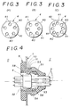
- the outer member 5 is engaged at the engagement groove 55 thereof as tightly fitted on the flange 11 of the wall 1 as shown in Fig. 4. Then, the inner member 4 in which the lead wires 3 already water-tightly set is pressed into the tight-fit portion 57 from the large-diameter retention hole 52 of the outer member 5 already fixed to the wall 1. Since the outer member 5 is deflectable at the tight-fit portion 57 thereof outwardly at this time because of the recess 58 formed in the outer member 1, the inner member 4 can be easily forced over the pawl 54 from the large-diameter retention hole into the tight-fit portion 57.
- the lead-wire grommet according to the present invention can be assembled in another manner which will be described below. Namely, the lead wires are water-tightly set in the inner member 4 as having been described above.
- the inner member 4 is water-tightly set in the tight-fit portion 57.
- the outer member 5 having the inner member 4 set therein is force-fitted at one end thereof into the opening 10 in the wall 1 as shown in Fig. 5. Since the outer member 5 is deflectable inwardly because of the recess 58 when forced into the opening 10 in the wall 1, it can be easily fit at the engagement groove 55 thereof on the flange 11 of the wall 1. Also in this case, the tightly fitted relation between the tight-fit portion 57 of the outer member 5 and the inner member 4 causes the walls of the slits 41 in the inner member 4 to closely fit each other, thus ensuring an improved watertightness of the structure.
- the lead-wire grommet according to the present invention can freely follow up with the movement of the lead wires 3 since the inner member 4 and the tight-fit portion 57, etc. of the outer member 5, which retains the inner member 4, are tiltable about the base 59 of the outer member 5 with respect to the inserting direction of the lead wires 3 as shown in Fig. 6. Therefore, no excessive force is applied to the portions where the walls of the slits 41 in the inner member 4 fit each other, the outer circumferences of the lead wire 3 fit the inner circumferences of the insertion holes 40 in the inner member 4, the outer circumference of the inner member 4 fit the inner circumference of the tight-fit portion 57 of the outer member 5, and the groove 5 in the outer member 5 fits the flange 11 of the wall 1, respectively.
- the close fitting of such portions is securely maintained so that the higher watertightness can be assured.
- the inside dimension B of the tight-fit portion 57 (medium-diameter retention hole 51) of the outer member 5 is to be taken as a common dimension and the outside dimensions C1, C2 and C3 of the engagement groove 55 in the outer member 5 are to be determined correspondingly to the inside diameters D1, D2 and D3, respectively, of the opening 10 in the wall 1.
- the outer members 5 by preparing various kinds of the outer members 5 different in outside diameters (D1, D2, D3) of the engagement groove 55 as shown in Figs. 7(A), 7(B) and 7(C), it is possible to use an inner member 4 having a predetermined outside diameter A (see Fig. 2) commonly with such outer members 5.
- the inner member 4 may have formed therein a selected number of insertion holes 40, for example, five, six or eight holes 40 as shown in Figs. 3(A), 3(B) or 3(C), for a number of lead wires which are to be passed through the inner member 4.
- a selected one of such inner members 4 having a same outside diameter A can be used with any of the above-mentioned outer members 5.
- the circular projection or bead 56 (not shown in Figs. 1, 4 and 6) having a triangular sectional shape is formed integrally on the surface, of the flange 505 of the outer member 5, which is to abut the surface of the wall 1 as having been previously described.
- the projection 56 is closely attached as collapsed to the surface of the wall 1, which also ensures a further improved watertightness between the outer member 5 and wall 1.
- both the opposite end faces 43 and 45 of the inner member 4 abut the step 53 and the flat face 541 of the pawl 54, respectively, of the outer member 5 so that the inner member 4 can be prevented from slipping out of the retention holes 50, 51 and 52 in the outer member 5.
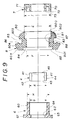
- Figs. 8 to 10 show together the second embodiment of the lead-wire grommet according to the present invention. Similar to the aforementioned first embodiment, this embodiment is used for water-tightly fixing, through a wall, lead wires connecting, for example, a rear combination lamp of a car and a power source to each other.
- lead wires connecting, for example, a rear combination lamp of a car and a power source to each other.
- the same reference numerals denote the same elements as in Figs. 1 to 7.
- reference numeral 8 denotes an outer member made of a synthetic rubber, for example, EPDM (ethylene propylene rubber).
- the outer member 5 has the general form of a truncated cone of which one end face 800 (right end face in Fig. 8) is formed as a small circle while the other end face 801 (left end face in Fig. 8) is as a large circle.
- the outer member 8 comprises a small-diameter curved portion 802 at the one end thereof, a medium-diameter tubular portion 803 contiguous from the curved end portion 802, an annular engagement groove 85 which will be discussed later, a large-diameter flange 804 at the other end thereof, a slope portion 805 of which the outside diameter gradually decreases as it goes from the flange 804 toward the other end face 801.
- This structure facilitates to fit the outer member 8 on the flange 804 of the opening 10 in the wall 1.
- the engagement groove 85 In the outer circumference of the outer member 8, there is formed between the tubular portion 803 and the flange 804 the engagement groove 85 at which the outer member 8 is tightly fitted on the flange 11 of the wall 1.
- the outside diameter J1, J2 or J3 of the engagement groove 85 is a little larger than the inside diameter D1, D2 or D3, respectively, of the opening 10 in the wall 1 so that the outer member 85 can be tightly fitted at the groove 85 thereof on the flange 11 of the wall 1.
- the width of the engagement groove 85 is nearly equal to or a little smaller than the length of the flange 11 of the wall 1.
- a circular projection or bead 86 having a triangular sectional shape is formed integrally on the surface, of the flange 804 of the outer member 8, which is to abut the surface of the wall 1.
- the outer member 8 has formed in the center thereof through-holes 80, 81 and 82 in which a cap 6 and ring 7, which will be discussed later, are to be retained as tightly fitted and through which the lead wires 3 are passed.
- these retention holes 80 to 82 the one 80 at one end of the outer member 8 has a large inside diameter E
- the middle retention hole 82 has a small inside diameter F
- the retention hole 82 at the other end has a large inside diameter.
- the inside diameter E of the retention hole 80 at the one end of the outer member 8 and the inside diameter F of the middle retention hole 81 are somewhat smaller than the outside diameter I of the ring 7 which will be discussed later and the outside diameter H of a cylindrical portion 60 of the cap 6 which will also be discussed later, so that the ring 7 and the cylindrical portion 60 are retained as tightly fitted in the inner-circumferential portions of retention holes 80 and 81.
- These inner-circumferential portions will be referred to as "tight-fit portions 87 and 88", respectively herein.
- the cap 6 is made of a synthetic resin and consists of the above-mentioned hollow cylindrical portion 60, a lid portion 61 integrally formed at one end of the cylindrical portion 60, and an opening 62 formed in the center of the lid portion 61 and which communicates with the inside of the cylindrical portion 60.
- the inside diameter G of the cylindrical portion 60 of the cap 6 is a little smaller than the outside diameter A of the inner member 4 so that the inner member 4 is held as tightly fitted in the cylindrical portion 60.
- the inner circumference of the cylindrical portion 60 will be referred to as a "tight-fit portion 64" herein.
- an inner surface 63 inside the cylindrical portion 61 serves as a stopper to receive one end face 43 of the inner member 4.
- the ring 7 is made of a synthetic resin. It has an opening 70 formed in the center thereof and also has formed at one end face thereof an annular engagement recess 71 in which the end of the cylindrical portion 60 of the cap 6 is to be fitted. Of the one end face of the ring 7, an inner surface 73 inside the engagement recess 71 serves as a stopper to receive the other end face 45 of the inner member 4.
- the second embodiment of the lead-wire grommet according to the present invention is constructed as having been described in the foregoing, and it is to be assembled as will be discussed below.
- the lead wire 3 is pressed into each insertion hole 40 in the inner member 5 through the slit 41.
- the lead wire 3 will thus be fitted in the insertion hole 40.
- the inner member 4 is pressed into the cylindrical portion 60 of the cap 6 and retained as tightly fit there and thus made to abut at one end face 43 thereof the stopper 63 of the lid portion 61 of the cap 6.
- the tight fitting between the cylindrical portion 60 of the cap 6 and the inner member 4 causes the walls of the slits 41 in the inner member 4 to closely fit each other, thus ensuring a higher watertightness.
- one end of the outer member 8 is pressed into the opening 10 in the wall 1 and the outer member 8 is tightly fitted at the engagement groove 85 thereof on the flange 11 of the opening 10 of the wall 1.
- the cylindrical portion 60 of the cap 6 and the ring 7 are pressed into the tight-fit portions 87 and 88 of the outer member 8 and retained as tightly fitted there.
- the stopper 73 of the ring 7 is made to abut the other end face 45 of the inner member 4 and further the flange 61 of the cap 6 and a portion 72 of the one end face of the ring 7, outside the engagement recess 71, are made to abut the steps 84 and 83, respectively, of the outer member 8.
- the cylindrical portion 60 of the cap 6 and the ring 7 are retained as tightly fitted in the tight-fit portions 87 and 88 of the outer member 8. As a result, the cap 6 and ring 7 will be positively secured in the outer member 8.
- the inner member 4 is held as tightly fitted in the cylindrical portion 60 of the cap 6, and both end faces 43 and 45 of the inner member 4 are forced to abut the stopper 63 of the cap 6 and the stopper 73 of the ring 7 from opposite sides in the inserting direction of the lead wires 3.
- the inner member 5 will be securely fixed in the outer member 8 by means of the cap 6 and ring 7. Therefore, it is possible to prevent the inner member 4 from slipping out of the outer member 8 in the directions of arrows a and b in Fig. 8.
- the inside dimensions E and F of the tight-fit portions 80 and 81 of the outer member 8 are to be taken as common dimensions and the outside dimensions J1, J2 and J3 of the engagement groove 85 in the outer member 8 are to be determined correspondingly to the inside diameters D1, D2 and D3, respectively, of the opening 10 in the wall 1.
- the outer members 8 by preparing various kinds of the outer members 8 different in outside diameters (J1, J2, J3) of the engagement groove 85 as shown in Figs.
- an inner member 8 having a predetermined outside diameter A, cap 6 having a predetermined outside diameter H and inside diameter G and a ring 7 having a predetermined outside diameter I commonly with such outer members 8.
- the circular projection or bead 86 (not shown in Fig. 8) having a triangular sectional shape, is formed integrally on the surface, of the cylindrical portion 80 of the outer member 8, which is to abut the wall 1, as having been previously described.
- the projection 86 is closely attached as collapsed to the surface of the wall 1, which also ensures a further high watertightness between the outer member 8 and wall 1.
- the flange may not always be provided at the edge of the opening 10 in the wall 1.
- the outer member 5 of the lead-wire grommet according to the present invention can be fitted at the engagement groove 55 thereof directly to the edge of the opening 10 of the wall 1.
- shapes of the opening 10 in the wall 1 and of the flange 11, profile of the inner member 4, shapes of the outer members 5 and 8, cap 6 and ring 7 are not limited to only those specified herein.
Landscapes
- Engineering & Computer Science (AREA)
- General Engineering & Computer Science (AREA)
- Mechanical Engineering (AREA)
- Architecture (AREA)
- Civil Engineering (AREA)
- Structural Engineering (AREA)
- Installation Of Indoor Wiring (AREA)
- Insulating Bodies (AREA)
Applications Claiming Priority (4)
| Application Number | Priority Date | Filing Date | Title |
|---|---|---|---|
| JP194054/92 | 1992-07-21 | ||
| JP194053/92 | 1992-07-21 | ||
| JP04194053A JP3121128B2 (ja) | 1992-07-21 | 1992-07-21 | コード用グロメット |
| JP4194054A JP3069439B2 (ja) | 1992-07-21 | 1992-07-21 | コード用グロメット |
Publications (1)
| Publication Number | Publication Date |
|---|---|
| EP0580130A1 true EP0580130A1 (fr) | 1994-01-26 |
Family
ID=26508271
Family Applications (1)
| Application Number | Title | Priority Date | Filing Date |
|---|---|---|---|
| EP93111613A Withdrawn EP0580130A1 (fr) | 1992-07-21 | 1993-07-20 | Traversée pour conducteurs électriques |
Country Status (1)
| Country | Link |
|---|---|
| EP (1) | EP0580130A1 (fr) |
Cited By (43)
| Publication number | Priority date | Publication date | Assignee | Title |
|---|---|---|---|---|
| WO1995032107A1 (fr) * | 1994-05-24 | 1995-11-30 | United Technologies Automotive, Inc. | Joint d'etancheite submersible a barriere radiale diffusive |
| FR2730785A1 (fr) * | 1995-02-17 | 1996-08-23 | Peugeot | Gaine de protection souple en caoutchouc pour assurer le passage d'un faisceau electrique ou d'un conduit |
| EP0735547A1 (fr) * | 1995-03-28 | 1996-10-02 | Sumitomo Wiring Systems, Ltd. | Douille de traversée et appareil de vérification |
| EP0821192A2 (fr) * | 1996-07-24 | 1998-01-28 | Tokai Rubber Industries, Ltd. | Dispositif de raccordement de tuyaux avec porte-connecteur en élastomère |
| EP0822121A2 (fr) * | 1996-08-01 | 1998-02-04 | Sumitomo Wiring Systems, Ltd. | Douille d'isolation de bruit et son procédé de fabrication |
| US5739475A (en) * | 1994-04-21 | 1998-04-14 | Inoac Corporation | Grommet for protecting a wire harness with structure for ensuring flush seating |
| US5775702A (en) * | 1994-03-07 | 1998-07-07 | N.V. Raychem S.A. | Sealing arrangement |
| US5856635A (en) * | 1995-03-09 | 1999-01-05 | Inoac Corporation | Grommet |
| EP0934850A1 (fr) * | 1997-12-11 | 1999-08-11 | Sumitomo Wiring Systems, Ltd. | Manchon et son procédé de fixation à un véhicule |
| US5973271A (en) * | 1997-12-11 | 1999-10-26 | Sumitomo Wiring Systems, Ltd | Grommet assembly including elastic pressing member |
| EP1026044A1 (fr) * | 1999-02-08 | 2000-08-09 | Société SYLEA | Ensemble de traversée de cloison |
| WO2001021907A1 (fr) * | 1999-09-23 | 2001-03-29 | Rotary Press Systems International Limited | Oeillet destine a etre utilise avec un element structural metallique |
| WO2001059501A1 (fr) * | 2000-02-11 | 2001-08-16 | Tyco Electronics Raychem Nv | Joint enveloppant pour fibres optiques |
| FR2809877A1 (fr) * | 2000-05-30 | 2001-12-07 | Peugeot Citroen Automobiles Sa | Dispositif de traversee etanche d'un faisceau electrique par une ouverture de passage a travers un tablier d'un vehicule automobile et procede de montage du faisceau dans l'ouverture |
| EP1193436A1 (fr) * | 2000-09-29 | 2002-04-03 | Sumitomo Wiring Systems, Ltd. | Manchon d'étanchéité |
| WO2002027230A3 (fr) * | 2000-09-28 | 2002-06-13 | Robertshaw Controls Co | Mecanisme d'etancheite a l'epreuve du feu |
| FR2842955A1 (fr) * | 2002-07-29 | 2004-01-30 | Peugeot Citroen Automobiles Sa | Systeme de raccordement d'un capteur de vitesse et d'un temoin d'usure de frein, au reste des circuits d'un vehicule |
| EP1564078A2 (fr) * | 2000-09-29 | 2005-08-17 | Sumitomo Wiring Systems, Ltd. | Manchon d'étanchéité |
| WO2005081376A1 (fr) * | 2004-02-25 | 2005-09-01 | Appulia Ltd | Dispositif d'entree de cable comprenant un moyen de reglage |
| WO2005081375A1 (fr) * | 2004-02-25 | 2005-09-01 | Appulia Ltd | Dispositif d'entree de cable permettant une installation facile |
| DE102005025780A1 (de) * | 2005-06-04 | 2006-12-14 | Leoni Bordnetz-Systeme Gmbh & Co Kg | Abdichtelement zur Abdichtung eines strangförmigen Körpers in einem Durchbruch einer Wand |
| EP1780851A1 (fr) | 2005-10-27 | 2007-05-02 | Pentair Water Pool and Spa, Inc. | Passage étanche de câbles pour niche d'éclairage dans une piscine ou bassin thermal |
| DE102005052832A1 (de) * | 2005-11-05 | 2007-05-10 | Audi Ag | Tülle zum Abdichten eines durch eine Wand verlaufenden Bauteiles |
| EP1870599A1 (fr) * | 2005-04-14 | 2007-12-26 | Sanden Corporation | Machine a fluide avec volute |
| DE102006045199A1 (de) * | 2006-09-25 | 2008-03-27 | Lisa Dräxlmaier GmbH | Kabelführung mit Dichtplatte |
| US7582836B2 (en) | 2004-02-25 | 2009-09-01 | Paul Tapper | Core for a cable entry device |
| FR2938626A1 (fr) * | 2008-11-17 | 2010-05-21 | Peugeot Citroen Automobiles Sa | Ensemble de raccordement etanche |
| WO2013019467A1 (fr) * | 2011-07-29 | 2013-02-07 | Corning Cable Systems Llc | Éléments de blocage et/ou de réduction de la tension de câbles de fibre optique |
| FR2986113A1 (fr) * | 2012-01-20 | 2013-07-26 | Renault Sa | Dispositif passe-cable d'interface entre deux organes |
| FR2996619A1 (fr) * | 2012-10-10 | 2014-04-11 | Renault Sa | Joint d'etancheite monobloc pour traversee de paroi et assemblage obtenu avec ce joint |
| CN103912730A (zh) * | 2013-01-09 | 2014-07-09 | 广西玉柴机器股份有限公司 | 柴油机油底壳管件连接结构 |
| CN104508930A (zh) * | 2012-04-26 | 2015-04-08 | 康宁光电通信有限责任公司 | 采用夹紧组件实现电缆应变消除的光纤外壳和相关组件以及方法 |
| US9110267B2 (en) | 2012-10-26 | 2015-08-18 | Ccs Technology, Inc. | Strain relief device for cables and fiber optic distribution device |
| EP2921792A1 (fr) * | 2014-03-19 | 2015-09-23 | Mitsubishi Heavy Industries, Ltd. | Climatiseur de type intégré et structure de support pour élément de tuyauterie |
| US9488793B2 (en) | 2013-09-10 | 2016-11-08 | Corning Optical Communications LLC | Combined optical fiber and power cable |
| EP3148025A4 (fr) * | 2014-06-26 | 2018-02-14 | AutoNetworks Technologies, Ltd. | Élément de scellement |
| US10066655B2 (en) | 2016-11-17 | 2018-09-04 | Orbital Atk, Inc. | Grommets and methods of installing grommets |
| CN108930841A (zh) * | 2018-08-17 | 2018-12-04 | 山西建筑工程集团有限公司 | 一种电缆群套管穿墙防水装置 |
| DE102017116985A1 (de) * | 2017-07-27 | 2019-01-31 | Eberspächer Climate Control Systems GmbH & Co. KG | Brennkammeranordnung |
| FR3080810A1 (fr) * | 2018-05-03 | 2019-11-08 | Psa Automobiles Sa | Dispositif de passage d’un cable a travers un carter d’un moteur thermique |
| EP4035949A1 (fr) * | 2021-01-27 | 2022-08-03 | AGCO International GmbH | Ensemble traversée de câbles pour véhicule |
| US11788650B1 (en) | 2019-02-22 | 2023-10-17 | Santiva Outdoors, L.L.C. | Outdoor apparatus |
| WO2024156513A1 (fr) * | 2023-01-24 | 2024-08-02 | Bayerische Motoren Werke Aktiengesellschaft | Composant et véhicule automobile |
Citations (10)
| Publication number | Priority date | Publication date | Assignee | Title |
|---|---|---|---|---|
| DE1039115B (de) * | 1953-02-04 | 1958-09-18 | Hellermann Ltd | Durchfuehrungspfropfen mit mehreren Bohrungen fuer mehradrige Kabel |
| US3244802A (en) * | 1964-02-20 | 1966-04-05 | Chrysler Corp | Resilient grommet and seal assembly |
| DE1285591B (de) * | 1962-10-29 | 1968-12-19 | Carr Fastener Co Ltd | Wanddurchfuehrung fuer elektrische Kabel od. dgl. |
| DE1750240A1 (de) * | 1968-04-10 | 1971-01-14 | Ver Flugtechnische Werke | Wanddurchfuehrung fuer Rohre,elektrische Kabel od.dgl. |
| US4226432A (en) * | 1978-01-31 | 1980-10-07 | Kawasaki Jukogyo Kabushiki Kaisha | Device for sealing electric wires |
| US4487998A (en) * | 1983-07-27 | 1984-12-11 | Amp Incorporated | Releasable grommet |
| DE3431617A1 (de) * | 1984-08-28 | 1986-03-06 | Fa. Lisa Dräxlmaier, 8313 Vilsbiburg | Feuchtigkeitsdichte leitungsfuehrung |
| DE3544785A1 (de) * | 1985-12-18 | 1987-06-19 | Bayerische Motoren Werke Ag | Abdichtungssystem fuer leitungen |
| US5068496A (en) * | 1990-10-31 | 1991-11-26 | Hubbell Incorporated | Snap-in connector |
| DE4109206C1 (fr) * | 1991-03-21 | 1992-05-21 | A. Raymond & Cie, Grenoble, Fr |
-
1993
- 1993-07-20 EP EP93111613A patent/EP0580130A1/fr not_active Withdrawn
Patent Citations (10)
| Publication number | Priority date | Publication date | Assignee | Title |
|---|---|---|---|---|
| DE1039115B (de) * | 1953-02-04 | 1958-09-18 | Hellermann Ltd | Durchfuehrungspfropfen mit mehreren Bohrungen fuer mehradrige Kabel |
| DE1285591B (de) * | 1962-10-29 | 1968-12-19 | Carr Fastener Co Ltd | Wanddurchfuehrung fuer elektrische Kabel od. dgl. |
| US3244802A (en) * | 1964-02-20 | 1966-04-05 | Chrysler Corp | Resilient grommet and seal assembly |
| DE1750240A1 (de) * | 1968-04-10 | 1971-01-14 | Ver Flugtechnische Werke | Wanddurchfuehrung fuer Rohre,elektrische Kabel od.dgl. |
| US4226432A (en) * | 1978-01-31 | 1980-10-07 | Kawasaki Jukogyo Kabushiki Kaisha | Device for sealing electric wires |
| US4487998A (en) * | 1983-07-27 | 1984-12-11 | Amp Incorporated | Releasable grommet |
| DE3431617A1 (de) * | 1984-08-28 | 1986-03-06 | Fa. Lisa Dräxlmaier, 8313 Vilsbiburg | Feuchtigkeitsdichte leitungsfuehrung |
| DE3544785A1 (de) * | 1985-12-18 | 1987-06-19 | Bayerische Motoren Werke Ag | Abdichtungssystem fuer leitungen |
| US5068496A (en) * | 1990-10-31 | 1991-11-26 | Hubbell Incorporated | Snap-in connector |
| DE4109206C1 (fr) * | 1991-03-21 | 1992-05-21 | A. Raymond & Cie, Grenoble, Fr |
Cited By (68)
| Publication number | Priority date | Publication date | Assignee | Title |
|---|---|---|---|---|
| US5775702A (en) * | 1994-03-07 | 1998-07-07 | N.V. Raychem S.A. | Sealing arrangement |
| EP0749641B1 (fr) * | 1994-03-07 | 1998-07-15 | N.V. Raychem S.A. | Agencement d'etancheite |
| US5739475A (en) * | 1994-04-21 | 1998-04-14 | Inoac Corporation | Grommet for protecting a wire harness with structure for ensuring flush seating |
| US5562292A (en) * | 1994-05-24 | 1996-10-08 | United Technologies Automotive, Inc. | Submergible seal with diffusive radial barrier |
| WO1995032107A1 (fr) * | 1994-05-24 | 1995-11-30 | United Technologies Automotive, Inc. | Joint d'etancheite submersible a barriere radiale diffusive |
| FR2730785A1 (fr) * | 1995-02-17 | 1996-08-23 | Peugeot | Gaine de protection souple en caoutchouc pour assurer le passage d'un faisceau electrique ou d'un conduit |
| US5856635A (en) * | 1995-03-09 | 1999-01-05 | Inoac Corporation | Grommet |
| EP0735547A1 (fr) * | 1995-03-28 | 1996-10-02 | Sumitomo Wiring Systems, Ltd. | Douille de traversée et appareil de vérification |
| US6035730A (en) * | 1995-03-28 | 2000-03-14 | Sumitomo Wiring Systems, Ltd. | Apparatus for checking grommets |
| US5777274A (en) * | 1995-03-28 | 1998-07-07 | Sumitomo Wiring Systems, Ltd | Grommet having an identifying portion for checking the grommet |
| EP0821192A2 (fr) * | 1996-07-24 | 1998-01-28 | Tokai Rubber Industries, Ltd. | Dispositif de raccordement de tuyaux avec porte-connecteur en élastomère |
| EP0821192A3 (fr) * | 1996-07-24 | 2000-04-05 | Tokai Rubber Industries, Ltd. | Dispositif de raccordement de tuyaux avec porte-connecteur en élastomère |
| EP0822121A3 (fr) * | 1996-08-01 | 1999-07-07 | Sumitomo Wiring Systems, Ltd. | Douille d'isolation de bruit et son procédé de fabrication |
| EP0822121A2 (fr) * | 1996-08-01 | 1998-02-04 | Sumitomo Wiring Systems, Ltd. | Douille d'isolation de bruit et son procédé de fabrication |
| CN1069272C (zh) * | 1996-08-01 | 2001-08-08 | 住友电装株式会社 | 一种防噪音的索环及其制造方法 |
| EP0934850A1 (fr) * | 1997-12-11 | 1999-08-11 | Sumitomo Wiring Systems, Ltd. | Manchon et son procédé de fixation à un véhicule |
| US5973271A (en) * | 1997-12-11 | 1999-10-26 | Sumitomo Wiring Systems, Ltd | Grommet assembly including elastic pressing member |
| US5977486A (en) * | 1997-12-11 | 1999-11-02 | Sumitomo Wiring Systems, Ltd. | Grommet assembly and method of attaching same to a vehicle |
| FR2789527A1 (fr) * | 1999-02-08 | 2000-08-11 | Sylea | Ensemble de traversee de cloisons |
| EP1026044A1 (fr) * | 1999-02-08 | 2000-08-09 | Société SYLEA | Ensemble de traversée de cloison |
| US6263634B1 (en) | 1999-09-23 | 2001-07-24 | Rotary Press Systems Inc. | Grommet for use with sheet metal structural member |
| WO2001021907A1 (fr) * | 1999-09-23 | 2001-03-29 | Rotary Press Systems International Limited | Oeillet destine a etre utilise avec un element structural metallique |
| WO2001059501A1 (fr) * | 2000-02-11 | 2001-08-16 | Tyco Electronics Raychem Nv | Joint enveloppant pour fibres optiques |
| FR2809877A1 (fr) * | 2000-05-30 | 2001-12-07 | Peugeot Citroen Automobiles Sa | Dispositif de traversee etanche d'un faisceau electrique par une ouverture de passage a travers un tablier d'un vehicule automobile et procede de montage du faisceau dans l'ouverture |
| WO2002027230A3 (fr) * | 2000-09-28 | 2002-06-13 | Robertshaw Controls Co | Mecanisme d'etancheite a l'epreuve du feu |
| EP1193436A1 (fr) * | 2000-09-29 | 2002-04-03 | Sumitomo Wiring Systems, Ltd. | Manchon d'étanchéité |
| US6489559B2 (en) | 2000-09-29 | 2002-12-03 | Sumitomo Wiring Systems, Ltd. | Grommet |
| EP1564078A2 (fr) * | 2000-09-29 | 2005-08-17 | Sumitomo Wiring Systems, Ltd. | Manchon d'étanchéité |
| EP1564078A3 (fr) * | 2000-09-29 | 2005-08-24 | Sumitomo Wiring Systems, Ltd. | Manchon d'étanchéité |
| FR2842955A1 (fr) * | 2002-07-29 | 2004-01-30 | Peugeot Citroen Automobiles Sa | Systeme de raccordement d'un capteur de vitesse et d'un temoin d'usure de frein, au reste des circuits d'un vehicule |
| EP1387447A1 (fr) * | 2002-07-29 | 2004-02-04 | Peugeot Citroen Automobiles SA | Système de raccordement d'un capteur de vitesse et d'un témoin d'usure de frein, au reste des circuits d'un véhicule |
| WO2005081375A1 (fr) * | 2004-02-25 | 2005-09-01 | Appulia Ltd | Dispositif d'entree de cable permettant une installation facile |
| WO2005081376A1 (fr) * | 2004-02-25 | 2005-09-01 | Appulia Ltd | Dispositif d'entree de cable comprenant un moyen de reglage |
| US7579557B2 (en) | 2004-02-25 | 2009-08-25 | Paul Tapper | Cable entry device for easy installation |
| US7582836B2 (en) | 2004-02-25 | 2009-09-01 | Paul Tapper | Core for a cable entry device |
| US7579556B2 (en) | 2004-02-25 | 2009-08-25 | Paul Tapper | Cable entry device comprising means for adjustment |
| EP1870599A4 (fr) * | 2005-04-14 | 2013-03-27 | Sanden Corp | Machine a fluide avec volute |
| EP1870599A1 (fr) * | 2005-04-14 | 2007-12-26 | Sanden Corporation | Machine a fluide avec volute |
| DE102005025780A1 (de) * | 2005-06-04 | 2006-12-14 | Leoni Bordnetz-Systeme Gmbh & Co Kg | Abdichtelement zur Abdichtung eines strangförmigen Körpers in einem Durchbruch einer Wand |
| EP1780851A1 (fr) | 2005-10-27 | 2007-05-02 | Pentair Water Pool and Spa, Inc. | Passage étanche de câbles pour niche d'éclairage dans une piscine ou bassin thermal |
| US20070097667A1 (en) * | 2005-10-27 | 2007-05-03 | Pentair Water Poola And Spa, Inc. | Cord seal for swimming pool and spa light niches |
| US7705240B2 (en) | 2005-10-27 | 2010-04-27 | Pentair Water Pool And Spa, Inc. | Cord seal for swimming pool and spa light niches |
| EP2284969A1 (fr) * | 2005-10-27 | 2011-02-16 | Pentair Water Pool and Spa, Inc. | Passage étanche de câbles pour niche d'éclairage dans une piscine ou bassin thermal |
| DE102005052832A1 (de) * | 2005-11-05 | 2007-05-10 | Audi Ag | Tülle zum Abdichten eines durch eine Wand verlaufenden Bauteiles |
| DE102006045199A1 (de) * | 2006-09-25 | 2008-03-27 | Lisa Dräxlmaier GmbH | Kabelführung mit Dichtplatte |
| FR2938626A1 (fr) * | 2008-11-17 | 2010-05-21 | Peugeot Citroen Automobiles Sa | Ensemble de raccordement etanche |
| WO2013019467A1 (fr) * | 2011-07-29 | 2013-02-07 | Corning Cable Systems Llc | Éléments de blocage et/ou de réduction de la tension de câbles de fibre optique |
| US9110266B2 (en) | 2011-07-29 | 2015-08-18 | Corning Cable Systems Llc | Fiber optic cables seal and/or strain relief members, and related assemblies and methods |
| FR2986113A1 (fr) * | 2012-01-20 | 2013-07-26 | Renault Sa | Dispositif passe-cable d'interface entre deux organes |
| CN104508930A (zh) * | 2012-04-26 | 2015-04-08 | 康宁光电通信有限责任公司 | 采用夹紧组件实现电缆应变消除的光纤外壳和相关组件以及方法 |
| CN104508930B (zh) * | 2012-04-26 | 2017-05-24 | 康宁光电通信有限责任公司 | 采用夹紧组件实现电缆应变消除的光纤外壳和相关组件以及方法 |
| FR2996619A1 (fr) * | 2012-10-10 | 2014-04-11 | Renault Sa | Joint d'etancheite monobloc pour traversee de paroi et assemblage obtenu avec ce joint |
| US9110267B2 (en) | 2012-10-26 | 2015-08-18 | Ccs Technology, Inc. | Strain relief device for cables and fiber optic distribution device |
| CN103912730A (zh) * | 2013-01-09 | 2014-07-09 | 广西玉柴机器股份有限公司 | 柴油机油底壳管件连接结构 |
| US9488793B2 (en) | 2013-09-10 | 2016-11-08 | Corning Optical Communications LLC | Combined optical fiber and power cable |
| EP2921792A1 (fr) * | 2014-03-19 | 2015-09-23 | Mitsubishi Heavy Industries, Ltd. | Climatiseur de type intégré et structure de support pour élément de tuyauterie |
| US10236671B2 (en) | 2014-06-26 | 2019-03-19 | Autonetworks Technologies, Ltd. | Sealing member |
| EP3148025A4 (fr) * | 2014-06-26 | 2018-02-14 | AutoNetworks Technologies, Ltd. | Élément de scellement |
| US10066655B2 (en) | 2016-11-17 | 2018-09-04 | Orbital Atk, Inc. | Grommets and methods of installing grommets |
| US11046149B2 (en) | 2017-07-27 | 2021-06-29 | Eberspächer Climate Control Systems GmbH | Combustion chamber assembly |
| CN109307261A (zh) * | 2017-07-27 | 2019-02-05 | 埃贝斯佩歇气候控制系统有限责任两合公司 | 燃烧室布置结构 |
| DE102017116985A1 (de) * | 2017-07-27 | 2019-01-31 | Eberspächer Climate Control Systems GmbH & Co. KG | Brennkammeranordnung |
| RU2691901C1 (ru) * | 2017-07-27 | 2019-06-18 | Эбершпехер Клаймит Контрол Системз Гмбх Унд Ко. Кг | Камера сгорания и способ сборки камеры сгорания |
| FR3080810A1 (fr) * | 2018-05-03 | 2019-11-08 | Psa Automobiles Sa | Dispositif de passage d’un cable a travers un carter d’un moteur thermique |
| CN108930841A (zh) * | 2018-08-17 | 2018-12-04 | 山西建筑工程集团有限公司 | 一种电缆群套管穿墙防水装置 |
| US11788650B1 (en) | 2019-02-22 | 2023-10-17 | Santiva Outdoors, L.L.C. | Outdoor apparatus |
| EP4035949A1 (fr) * | 2021-01-27 | 2022-08-03 | AGCO International GmbH | Ensemble traversée de câbles pour véhicule |
| WO2024156513A1 (fr) * | 2023-01-24 | 2024-08-02 | Bayerische Motoren Werke Aktiengesellschaft | Composant et véhicule automobile |
Similar Documents
| Publication | Publication Date | Title |
|---|---|---|
| EP0580130A1 (fr) | Traversée pour conducteurs électriques | |
| US4754993A (en) | Conduit harness connector assembly | |
| US4383692A (en) | Grommet seal | |
| US6815615B1 (en) | Two-part grommet | |
| US6240597B1 (en) | Grommet having a resilient flange | |
| EP0731000A3 (fr) | Douille de traversée | |
| CN113346430B (zh) | 索环和线束 | |
| US20190351850A1 (en) | Grommet and wire harness | |
| JP2021125911A (ja) | グロメット、及び、ワイヤハーネス | |
| US6101674A (en) | Grommet | |
| CN110137895B (zh) | 索环、电子构件和形成索环的方法 | |
| US5452494A (en) | Sealing grommet | |
| JP3121128B2 (ja) | コード用グロメット | |
| CN111987683B (zh) | 线束 | |
| JP3627867B2 (ja) | グロメット | |
| JPH11126649A (ja) | キャップ部材のロック構造 | |
| JP3069439B2 (ja) | コード用グロメット | |
| EP0774608A1 (fr) | Ensemble de boîtier de dérivation avec adaptateurs pour la connexion de tuyaux et/ou gaines spiralées de diamètres différents | |
| GB1567613A (en) | Seath for the reception of electrical cables cable operating gear or other such parts | |
| JP6673429B2 (ja) | グロメットおよびワイヤハーネス | |
| JPH0613333U (ja) | コード用グロメット | |
| JPH08185746A (ja) | グロメット | |
| JPH0613332U (ja) | コード用グロメット | |
| JPH09198943A (ja) | 電気機器用ブッシング | |
| JPH1186838A (ja) | バッテリ用接続具 |
Legal Events
| Date | Code | Title | Description |
|---|---|---|---|
| PUAI | Public reference made under article 153(3) epc to a published international application that has entered the european phase |
Free format text: ORIGINAL CODE: 0009012 |
|
| AK | Designated contracting states |
Kind code of ref document: A1 Designated state(s): DE FR GB |
|
| 17P | Request for examination filed |
Effective date: 19940628 |
|
| 17Q | First examination report despatched |
Effective date: 19950518 |
|
| STAA | Information on the status of an ep patent application or granted ep patent |
Free format text: STATUS: THE APPLICATION IS DEEMED TO BE WITHDRAWN |
|
| 18D | Application deemed to be withdrawn |
Effective date: 19950929 |