EP3144052B1 - Membranes tfc à nanoparticules hybrides - Google Patents
Membranes tfc à nanoparticules hybrides Download PDFInfo
- Publication number
- EP3144052B1 EP3144052B1 EP16188716.1A EP16188716A EP3144052B1 EP 3144052 B1 EP3144052 B1 EP 3144052B1 EP 16188716 A EP16188716 A EP 16188716A EP 3144052 B1 EP3144052 B1 EP 3144052B1
- Authority
- EP
- European Patent Office
- Prior art keywords
- membrane
- nanoparticles
- solution
- flux
- tmc
- Prior art date
- Legal status (The legal status is an assumption and is not a legal conclusion. Google has not performed a legal analysis and makes no representation as to the accuracy of the status listed.)
- Active
Links
- 239000012528 membrane Substances 0.000 title claims description 443
- 239000002105 nanoparticle Substances 0.000 title description 215
- 239000000654 additive Substances 0.000 claims description 150
- 238000001223 reverse osmosis Methods 0.000 claims description 82
- 230000000996 additive effect Effects 0.000 claims description 71
- 238000012695 Interfacial polymerization Methods 0.000 claims description 57
- 238000000034 method Methods 0.000 claims description 54
- 239000000178 monomer Substances 0.000 claims description 46
- 150000001875 compounds Chemical class 0.000 claims description 35
- 238000006243 chemical reaction Methods 0.000 claims description 29
- 238000006116 polymerization reaction Methods 0.000 claims description 21
- CUJRVFIICFDLGR-UHFFFAOYSA-N acetylacetonate Chemical compound CC(=O)[CH-]C(C)=O CUJRVFIICFDLGR-UHFFFAOYSA-N 0.000 claims description 19
- 230000008569 process Effects 0.000 claims description 17
- 150000001266 acyl halides Chemical class 0.000 claims description 16
- 229910052784 alkaline earth metal Inorganic materials 0.000 claims description 14
- 150000001342 alkaline earth metals Chemical class 0.000 claims description 14
- 229910052791 calcium Inorganic materials 0.000 claims description 9
- 229910052749 magnesium Inorganic materials 0.000 claims description 8
- 229910052712 strontium Inorganic materials 0.000 claims description 8
- 229920000768 polyamine Polymers 0.000 claims description 4
- POILWHVDKZOXJZ-ARJAWSKDSA-M (z)-4-oxopent-2-en-2-olate Chemical compound C\C([O-])=C\C(C)=O POILWHVDKZOXJZ-ARJAWSKDSA-M 0.000 claims description 3
- 125000005595 acetylacetonate group Chemical group 0.000 claims 2
- 239000000243 solution Substances 0.000 description 198
- 230000004907 flux Effects 0.000 description 136
- 239000010410 layer Substances 0.000 description 109
- UWCPYKQBIPYOLX-UHFFFAOYSA-N benzene-1,3,5-tricarbonyl chloride Chemical compound ClC(=O)C1=CC(C(Cl)=O)=CC(C(Cl)=O)=C1 UWCPYKQBIPYOLX-UHFFFAOYSA-N 0.000 description 101
- XLYOFNOQVPJJNP-UHFFFAOYSA-N water Substances O XLYOFNOQVPJJNP-UHFFFAOYSA-N 0.000 description 74
- 239000012074 organic phase Substances 0.000 description 54
- 229910001868 water Inorganic materials 0.000 description 49
- 239000008346 aqueous phase Substances 0.000 description 43
- 239000000969 carrier Substances 0.000 description 41
- 239000010457 zeolite Substances 0.000 description 40
- NIXOWILDQLNWCW-UHFFFAOYSA-N acrylic acid group Chemical group C(C=C)(=O)O NIXOWILDQLNWCW-UHFFFAOYSA-N 0.000 description 30
- 229910021645 metal ion Inorganic materials 0.000 description 30
- 229910052751 metal Inorganic materials 0.000 description 29
- 239000002184 metal Substances 0.000 description 29
- 239000011521 glass Substances 0.000 description 28
- 229920000642 polymer Polymers 0.000 description 27
- 229910021536 Zeolite Inorganic materials 0.000 description 26
- HNPSIPDUKPIQMN-UHFFFAOYSA-N dioxosilane;oxo(oxoalumanyloxy)alumane Chemical compound O=[Si]=O.O=[Al]O[Al]=O HNPSIPDUKPIQMN-UHFFFAOYSA-N 0.000 description 26
- 238000012545 processing Methods 0.000 description 26
- 150000003839 salts Chemical class 0.000 description 25
- 230000006872 improvement Effects 0.000 description 24
- 239000002071 nanotube Substances 0.000 description 23
- 239000007864 aqueous solution Substances 0.000 description 22
- ZMXDDKWLCZADIW-UHFFFAOYSA-N N,N-Dimethylformamide Chemical compound CN(C)C=O ZMXDDKWLCZADIW-UHFFFAOYSA-N 0.000 description 21
- 239000007788 liquid Substances 0.000 description 21
- 239000000463 material Substances 0.000 description 21
- 239000000203 mixture Substances 0.000 description 20
- 229910052782 aluminium Inorganic materials 0.000 description 19
- -1 aluminum ions Chemical class 0.000 description 19
- 239000006185 dispersion Substances 0.000 description 19
- 239000002114 nanocomposite Substances 0.000 description 19
- 150000001412 amines Chemical class 0.000 description 18
- 239000006184 cosolvent Substances 0.000 description 15
- 229920002492 poly(sulfone) Polymers 0.000 description 15
- 238000000527 sonication Methods 0.000 description 15
- 238000012360 testing method Methods 0.000 description 15
- 239000010409 thin film Substances 0.000 description 15
- XAGFODPZIPBFFR-UHFFFAOYSA-N aluminium Chemical compound [Al] XAGFODPZIPBFFR-UHFFFAOYSA-N 0.000 description 14
- 238000004519 manufacturing process Methods 0.000 description 14
- CNPVJWYWYZMPDS-UHFFFAOYSA-N 2-methyldecane Chemical compound CCCCCCCCC(C)C CNPVJWYWYZMPDS-UHFFFAOYSA-N 0.000 description 13
- 230000035699 permeability Effects 0.000 description 13
- 239000004744 fabric Substances 0.000 description 12
- DBMJMQXJHONAFJ-UHFFFAOYSA-M Sodium laurylsulphate Chemical compound [Na+].CCCCCCCCCCCCOS([O-])(=O)=O DBMJMQXJHONAFJ-UHFFFAOYSA-M 0.000 description 11
- 230000000694 effects Effects 0.000 description 11
- 239000000376 reactant Substances 0.000 description 11
- 235000019333 sodium laurylsulphate Nutrition 0.000 description 11
- 239000002904 solvent Substances 0.000 description 11
- OKTJSMMVPCPJKN-UHFFFAOYSA-N Carbon Chemical compound [C] OKTJSMMVPCPJKN-UHFFFAOYSA-N 0.000 description 10
- 239000003125 aqueous solvent Substances 0.000 description 10
- 230000009286 beneficial effect Effects 0.000 description 10
- 230000008901 benefit Effects 0.000 description 10
- 238000000576 coating method Methods 0.000 description 10
- 238000001035 drying Methods 0.000 description 10
- 229910052500 inorganic mineral Inorganic materials 0.000 description 10
- 239000002245 particle Substances 0.000 description 10
- 241000894007 species Species 0.000 description 10
- YXFVVABEGXRONW-UHFFFAOYSA-N Toluene Chemical compound CC1=CC=CC=C1 YXFVVABEGXRONW-UHFFFAOYSA-N 0.000 description 9
- 125000003118 aryl group Chemical group 0.000 description 9
- 230000015572 biosynthetic process Effects 0.000 description 9
- VLKZOEOYAKHREP-UHFFFAOYSA-N n-Hexane Chemical compound CCCCCC VLKZOEOYAKHREP-UHFFFAOYSA-N 0.000 description 9
- 238000003756 stirring Methods 0.000 description 9
- 239000004952 Polyamide Substances 0.000 description 8
- CDBYLPFSWZWCQE-UHFFFAOYSA-L Sodium Carbonate Chemical compound [Na+].[Na+].[O-]C([O-])=O CDBYLPFSWZWCQE-UHFFFAOYSA-L 0.000 description 8
- 239000002253 acid Substances 0.000 description 8
- QMKYBPDZANOJGF-UHFFFAOYSA-N benzene-1,3,5-tricarboxylic acid Chemical compound OC(=O)C1=CC(C(O)=O)=CC(C(O)=O)=C1 QMKYBPDZANOJGF-UHFFFAOYSA-N 0.000 description 8
- 239000011575 calcium Substances 0.000 description 8
- 239000003054 catalyst Substances 0.000 description 8
- 238000005056 compaction Methods 0.000 description 8
- 230000003247 decreasing effect Effects 0.000 description 8
- 239000002798 polar solvent Substances 0.000 description 8
- 229920002647 polyamide Polymers 0.000 description 8
- 239000000047 product Substances 0.000 description 8
- 239000004094 surface-active agent Substances 0.000 description 8
- ANBBXQWFNXMHLD-UHFFFAOYSA-N aluminum;sodium;oxygen(2-) Chemical compound [O-2].[O-2].[Na+].[Al+3] ANBBXQWFNXMHLD-UHFFFAOYSA-N 0.000 description 7
- 239000000356 contaminant Substances 0.000 description 7
- 230000007423 decrease Effects 0.000 description 7
- 150000002500 ions Chemical class 0.000 description 7
- 239000012044 organic layer Substances 0.000 description 7
- 239000012071 phase Substances 0.000 description 7
- 229920006254 polymer film Polymers 0.000 description 7
- 229910001388 sodium aluminate Inorganic materials 0.000 description 7
- 230000032258 transport Effects 0.000 description 7
- ZVYYAYJIGYODSD-LNTINUHCSA-K (z)-4-bis[[(z)-4-oxopent-2-en-2-yl]oxy]gallanyloxypent-3-en-2-one Chemical compound [Ga+3].C\C([O-])=C\C(C)=O.C\C([O-])=C\C(C)=O.C\C([O-])=C\C(C)=O ZVYYAYJIGYODSD-LNTINUHCSA-K 0.000 description 6
- WEVYAHXRMPXWCK-UHFFFAOYSA-N Acetonitrile Chemical compound CC#N WEVYAHXRMPXWCK-UHFFFAOYSA-N 0.000 description 6
- UHOVQNZJYSORNB-UHFFFAOYSA-N Benzene Chemical compound C1=CC=CC=C1 UHOVQNZJYSORNB-UHFFFAOYSA-N 0.000 description 6
- YMWUJEATGCHHMB-UHFFFAOYSA-N Dichloromethane Chemical compound ClCCl YMWUJEATGCHHMB-UHFFFAOYSA-N 0.000 description 6
- 238000005266 casting Methods 0.000 description 6
- 239000011248 coating agent Substances 0.000 description 6
- 239000002131 composite material Substances 0.000 description 6
- 238000010586 diagram Methods 0.000 description 6
- 229930195733 hydrocarbon Natural products 0.000 description 6
- 239000012535 impurity Substances 0.000 description 6
- 238000010348 incorporation Methods 0.000 description 6
- 239000011777 magnesium Substances 0.000 description 6
- 238000002360 preparation method Methods 0.000 description 6
- 239000013535 sea water Substances 0.000 description 6
- WZCQRUWWHSTZEM-UHFFFAOYSA-N 1,3-phenylenediamine Chemical compound NC1=CC=CC(N)=C1 WZCQRUWWHSTZEM-UHFFFAOYSA-N 0.000 description 5
- CTQNGGLPUBDAKN-UHFFFAOYSA-N O-Xylene Chemical compound CC1=CC=CC=C1C CTQNGGLPUBDAKN-UHFFFAOYSA-N 0.000 description 5
- VYPSYNLAJGMNEJ-UHFFFAOYSA-N Silicium dioxide Chemical compound O=[Si]=O VYPSYNLAJGMNEJ-UHFFFAOYSA-N 0.000 description 5
- FAPWRFPIFSIZLT-UHFFFAOYSA-M Sodium chloride Chemical compound [Na+].[Cl-] FAPWRFPIFSIZLT-UHFFFAOYSA-M 0.000 description 5
- 239000002041 carbon nanotube Substances 0.000 description 5
- 229910021393 carbon nanotube Inorganic materials 0.000 description 5
- 150000004696 coordination complex Chemical class 0.000 description 5
- 238000004090 dissolution Methods 0.000 description 5
- 238000001704 evaporation Methods 0.000 description 5
- 230000008020 evaporation Effects 0.000 description 5
- 239000010408 film Substances 0.000 description 5
- 239000003999 initiator Substances 0.000 description 5
- XEEYBQQBJWHFJM-UHFFFAOYSA-N iron Substances [Fe] XEEYBQQBJWHFJM-UHFFFAOYSA-N 0.000 description 5
- 239000011159 matrix material Substances 0.000 description 5
- AUHZEENZYGFFBQ-UHFFFAOYSA-N mesitylene Substances CC1=CC(C)=CC(C)=C1 AUHZEENZYGFFBQ-UHFFFAOYSA-N 0.000 description 5
- 125000001827 mesitylenyl group Chemical group [H]C1=C(C(*)=C(C([H])=C1C([H])([H])[H])C([H])([H])[H])C([H])([H])[H] 0.000 description 5
- 244000005700 microbiome Species 0.000 description 5
- 239000011707 mineral Substances 0.000 description 5
- 239000011148 porous material Substances 0.000 description 5
- 239000008213 purified water Substances 0.000 description 5
- 239000000523 sample Substances 0.000 description 5
- 239000008096 xylene Substances 0.000 description 5
- OYPRJOBELJOOCE-UHFFFAOYSA-N Calcium Chemical compound [Ca] OYPRJOBELJOOCE-UHFFFAOYSA-N 0.000 description 4
- YNQLUTRBYVCPMQ-UHFFFAOYSA-N Ethylbenzene Chemical compound CCC1=CC=CC=C1 YNQLUTRBYVCPMQ-UHFFFAOYSA-N 0.000 description 4
- 238000005481 NMR spectroscopy Methods 0.000 description 4
- YGYAWVDWMABLBF-UHFFFAOYSA-N Phosgene Chemical class ClC(Cl)=O YGYAWVDWMABLBF-UHFFFAOYSA-N 0.000 description 4
- GLUUGHFHXGJENI-UHFFFAOYSA-N Piperazine Chemical compound C1CNCCN1 GLUUGHFHXGJENI-UHFFFAOYSA-N 0.000 description 4
- 229920003171 Poly (ethylene oxide) Polymers 0.000 description 4
- 125000000217 alkyl group Chemical group 0.000 description 4
- 229910000323 aluminium silicate Inorganic materials 0.000 description 4
- VSCWAEJMTAWNJL-UHFFFAOYSA-K aluminium trichloride Chemical compound Cl[Al](Cl)Cl VSCWAEJMTAWNJL-UHFFFAOYSA-K 0.000 description 4
- 238000004458 analytical method Methods 0.000 description 4
- 125000004429 atom Chemical group 0.000 description 4
- 229910052799 carbon Inorganic materials 0.000 description 4
- 230000008859 change Effects 0.000 description 4
- 238000011109 contamination Methods 0.000 description 4
- RTZKZFJDLAIYFH-UHFFFAOYSA-N ether Substances CCOCC RTZKZFJDLAIYFH-UHFFFAOYSA-N 0.000 description 4
- 150000004820 halides Chemical class 0.000 description 4
- BXWNKGSJHAJOGX-UHFFFAOYSA-N hexadecan-1-ol Chemical compound CCCCCCCCCCCCCCCCO BXWNKGSJHAJOGX-UHFFFAOYSA-N 0.000 description 4
- 150000002430 hydrocarbons Chemical class 0.000 description 4
- 229910052742 iron Inorganic materials 0.000 description 4
- 238000000746 purification Methods 0.000 description 4
- 230000004044 response Effects 0.000 description 4
- 229910000029 sodium carbonate Inorganic materials 0.000 description 4
- CIOAGBVUUVVLOB-UHFFFAOYSA-N strontium atom Chemical compound [Sr] CIOAGBVUUVVLOB-UHFFFAOYSA-N 0.000 description 4
- 239000002352 surface water Substances 0.000 description 4
- 238000003786 synthesis reaction Methods 0.000 description 4
- ZUGAOYSWHHGDJY-UHFFFAOYSA-K 5-hydroxy-2,8,9-trioxa-1-aluminabicyclo[3.3.2]decane-3,7,10-trione Chemical compound [Al+3].[O-]C(=O)CC(O)(CC([O-])=O)C([O-])=O ZUGAOYSWHHGDJY-UHFFFAOYSA-K 0.000 description 3
- 241000269350 Anura Species 0.000 description 3
- FYYHWMGAXLPEAU-UHFFFAOYSA-N Magnesium Chemical compound [Mg] FYYHWMGAXLPEAU-UHFFFAOYSA-N 0.000 description 3
- SECXISVLQFMRJM-UHFFFAOYSA-N N-Methylpyrrolidone Chemical compound CN1CCCC1=O SECXISVLQFMRJM-UHFFFAOYSA-N 0.000 description 3
- QAOWNCQODCNURD-UHFFFAOYSA-L Sulfate Chemical compound [O-]S([O-])(=O)=O QAOWNCQODCNURD-UHFFFAOYSA-L 0.000 description 3
- ZMANZCXQSJIPKH-UHFFFAOYSA-N Triethylamine Chemical compound CCN(CC)CC ZMANZCXQSJIPKH-UHFFFAOYSA-N 0.000 description 3
- AZDRQVAHHNSJOQ-UHFFFAOYSA-N alumane Chemical group [AlH3] AZDRQVAHHNSJOQ-UHFFFAOYSA-N 0.000 description 3
- KRKNYBCHXYNGOX-UHFFFAOYSA-N citric acid Chemical compound OC(=O)CC(O)(C(O)=O)CC(O)=O KRKNYBCHXYNGOX-UHFFFAOYSA-N 0.000 description 3
- 239000010949 copper Substances 0.000 description 3
- 239000002178 crystalline material Substances 0.000 description 3
- 238000002425 crystallisation Methods 0.000 description 3
- 230000008025 crystallization Effects 0.000 description 3
- 238000010612 desalination reaction Methods 0.000 description 3
- 238000009792 diffusion process Methods 0.000 description 3
- 230000009881 electrostatic interaction Effects 0.000 description 3
- XLYOFNOQVPJJNP-UHFFFAOYSA-M hydroxide Chemical compound [OH-] XLYOFNOQVPJJNP-UHFFFAOYSA-M 0.000 description 3
- 230000003993 interaction Effects 0.000 description 3
- 239000002808 molecular sieve Substances 0.000 description 3
- 239000004745 nonwoven fabric Substances 0.000 description 3
- 230000000269 nucleophilic effect Effects 0.000 description 3
- 239000005416 organic matter Substances 0.000 description 3
- URGAHOPLAPQHLN-UHFFFAOYSA-N sodium aluminosilicate Chemical compound [Na+].[Al+3].[O-][Si]([O-])=O.[O-][Si]([O-])=O URGAHOPLAPQHLN-UHFFFAOYSA-N 0.000 description 3
- 239000011780 sodium chloride Substances 0.000 description 3
- 238000002525 ultrasonication Methods 0.000 description 3
- 239000003643 water by type Substances 0.000 description 3
- 238000002424 x-ray crystallography Methods 0.000 description 3
- ALSTYHKOOCGGFT-KTKRTIGZSA-N (9Z)-octadecen-1-ol Chemical compound CCCCCCCC\C=C/CCCCCCCCO ALSTYHKOOCGGFT-KTKRTIGZSA-N 0.000 description 2
- 238000005160 1H NMR spectroscopy Methods 0.000 description 2
- CSCPPACGZOOCGX-UHFFFAOYSA-N Acetone Chemical class CC(C)=O CSCPPACGZOOCGX-UHFFFAOYSA-N 0.000 description 2
- XMWRBQBLMFGWIX-UHFFFAOYSA-N C60 fullerene Chemical compound C12=C3C(C4=C56)=C7C8=C5C5=C9C%10=C6C6=C4C1=C1C4=C6C6=C%10C%10=C9C9=C%11C5=C8C5=C8C7=C3C3=C7C2=C1C1=C2C4=C6C4=C%10C6=C9C9=C%11C5=C5C8=C3C3=C7C1=C1C2=C4C6=C2C9=C5C3=C12 XMWRBQBLMFGWIX-UHFFFAOYSA-N 0.000 description 2
- 239000004215 Carbon black (E152) Substances 0.000 description 2
- 239000006057 Non-nutritive feed additive Substances 0.000 description 2
- 229910019142 PO4 Inorganic materials 0.000 description 2
- GWEVSGVZZGPLCZ-UHFFFAOYSA-N Titan oxide Chemical compound O=[Ti]=O GWEVSGVZZGPLCZ-UHFFFAOYSA-N 0.000 description 2
- 238000009825 accumulation Methods 0.000 description 2
- 239000000956 alloy Substances 0.000 description 2
- 229910045601 alloy Inorganic materials 0.000 description 2
- 229910000147 aluminium phosphate Inorganic materials 0.000 description 2
- JXBLBCCCEIUYHZ-UHFFFAOYSA-K aluminum (7,7-dimethyl-2-oxo-1-bicyclo[2.2.1]heptanyl)methanesulfonate Chemical compound [Al+3].CC1(C)C2CCC1(CS([O-])(=O)=O)C(=O)C2.CC1(C)C2CCC1(CS([O-])(=O)=O)C(=O)C2.CC1(C)C2CCC1(CS([O-])(=O)=O)C(=O)C2 JXBLBCCCEIUYHZ-UHFFFAOYSA-K 0.000 description 2
- 125000003277 amino group Chemical group 0.000 description 2
- 125000000129 anionic group Chemical group 0.000 description 2
- 239000003945 anionic surfactant Substances 0.000 description 2
- MWPLVEDNUUSJAV-UHFFFAOYSA-N anthracene Chemical class C1=CC=CC2=CC3=CC=CC=C3C=C21 MWPLVEDNUUSJAV-UHFFFAOYSA-N 0.000 description 2
- 239000003849 aromatic solvent Substances 0.000 description 2
- JSYBAZQQYCNZJE-UHFFFAOYSA-N benzene-1,2,4-triamine Chemical compound NC1=CC=C(N)C(N)=C1 JSYBAZQQYCNZJE-UHFFFAOYSA-N 0.000 description 2
- CJPIDIRJSIUWRJ-UHFFFAOYSA-N benzene-1,2,4-tricarbonyl chloride Chemical compound ClC(=O)C1=CC=C(C(Cl)=O)C(C(Cl)=O)=C1 CJPIDIRJSIUWRJ-UHFFFAOYSA-N 0.000 description 2
- 238000009835 boiling Methods 0.000 description 2
- 238000001354 calcination Methods 0.000 description 2
- 150000001732 carboxylic acid derivatives Chemical group 0.000 description 2
- 125000002843 carboxylic acid group Chemical group 0.000 description 2
- 125000002091 cationic group Chemical group 0.000 description 2
- 239000003093 cationic surfactant Substances 0.000 description 2
- 210000004027 cell Anatomy 0.000 description 2
- 229960000541 cetyl alcohol Drugs 0.000 description 2
- 239000003153 chemical reaction reagent Substances 0.000 description 2
- 238000010924 continuous production Methods 0.000 description 2
- 238000007796 conventional method Methods 0.000 description 2
- 229920001577 copolymer Polymers 0.000 description 2
- 229910052802 copper Inorganic materials 0.000 description 2
- WOQQAWHSKSSAGF-WXFJLFHKSA-N decyl beta-D-maltopyranoside Chemical compound O[C@@H]1[C@@H](O)[C@H](OCCCCCCCCCC)O[C@H](CO)[C@H]1O[C@@H]1[C@H](O)[C@@H](O)[C@H](O)[C@@H](CO)O1 WOQQAWHSKSSAGF-WXFJLFHKSA-N 0.000 description 2
- 239000008367 deionised water Substances 0.000 description 2
- 229910021641 deionized water Inorganic materials 0.000 description 2
- 230000001419 dependent effect Effects 0.000 description 2
- 230000008021 deposition Effects 0.000 description 2
- CSCPPACGZOOCGX-WFGJKAKNSA-N deuterated acetone Substances [2H]C([2H])([2H])C(=O)C([2H])([2H])[2H] CSCPPACGZOOCGX-WFGJKAKNSA-N 0.000 description 2
- 238000010790 dilution Methods 0.000 description 2
- 239000012895 dilution Substances 0.000 description 2
- ZUOUZKKEUPVFJK-UHFFFAOYSA-N diphenyl Chemical class C1=CC=CC=C1C1=CC=CC=C1 ZUOUZKKEUPVFJK-UHFFFAOYSA-N 0.000 description 2
- 238000007598 dipping method Methods 0.000 description 2
- 239000012153 distilled water Substances 0.000 description 2
- 239000012154 double-distilled water Substances 0.000 description 2
- 239000012039 electrophile Substances 0.000 description 2
- 238000005516 engineering process Methods 0.000 description 2
- 238000002474 experimental method Methods 0.000 description 2
- 150000002191 fatty alcohols Chemical class 0.000 description 2
- 239000000835 fiber Substances 0.000 description 2
- 238000001914 filtration Methods 0.000 description 2
- 230000006870 function Effects 0.000 description 2
- 150000004676 glycans Chemical class 0.000 description 2
- 125000002887 hydroxy group Chemical group [H]O* 0.000 description 2
- AMWRITDGCCNYAT-UHFFFAOYSA-L hydroxy(oxo)manganese;manganese Chemical compound [Mn].O[Mn]=O.O[Mn]=O AMWRITDGCCNYAT-UHFFFAOYSA-L 0.000 description 2
- 229910010272 inorganic material Inorganic materials 0.000 description 2
- 239000011147 inorganic material Substances 0.000 description 2
- 229940018564 m-phenylenediamine Drugs 0.000 description 2
- 238000009285 membrane fouling Methods 0.000 description 2
- 239000013335 mesoporous material Substances 0.000 description 2
- 239000002207 metabolite Substances 0.000 description 2
- 239000012229 microporous material Substances 0.000 description 2
- 238000012544 monitoring process Methods 0.000 description 2
- 239000004570 mortar (masonry) Substances 0.000 description 2
- 239000002736 nonionic surfactant Substances 0.000 description 2
- 150000007523 nucleic acids Chemical class 0.000 description 2
- 102000039446 nucleic acids Human genes 0.000 description 2
- 108020004707 nucleic acids Proteins 0.000 description 2
- HEGSGKPQLMEBJL-RKQHYHRCSA-N octyl beta-D-glucopyranoside Chemical compound CCCCCCCCO[C@@H]1O[C@H](CO)[C@@H](O)[C@H](O)[C@H]1O HEGSGKPQLMEBJL-RKQHYHRCSA-N 0.000 description 2
- 229940055577 oleyl alcohol Drugs 0.000 description 2
- XMLQWXUVTXCDDL-UHFFFAOYSA-N oleyl alcohol Natural products CCCCCCC=CCCCCCCCCCCO XMLQWXUVTXCDDL-UHFFFAOYSA-N 0.000 description 2
- 239000011368 organic material Substances 0.000 description 2
- FDPIMTJIUBPUKL-UHFFFAOYSA-N pentan-3-one Chemical compound CCC(=O)CC FDPIMTJIUBPUKL-UHFFFAOYSA-N 0.000 description 2
- YNPNZTXNASCQKK-UHFFFAOYSA-N phenanthrene Chemical class C1=CC=C2C3=CC=CC=C3C=CC2=C1 YNPNZTXNASCQKK-UHFFFAOYSA-N 0.000 description 2
- 229920001983 poloxamer Polymers 0.000 description 2
- 229920001987 poloxamine Polymers 0.000 description 2
- 230000000379 polymerizing effect Effects 0.000 description 2
- 229920001451 polypropylene glycol Polymers 0.000 description 2
- 229920001282 polysaccharide Polymers 0.000 description 2
- 239000005017 polysaccharide Substances 0.000 description 2
- 229910001746 prehnite Inorganic materials 0.000 description 2
- 239000011027 prehnite Substances 0.000 description 2
- 102000004169 proteins and genes Human genes 0.000 description 2
- 108090000623 proteins and genes Proteins 0.000 description 2
- 230000009467 reduction Effects 0.000 description 2
- 239000013049 sediment Substances 0.000 description 2
- 239000000377 silicon dioxide Substances 0.000 description 2
- 239000007787 solid Substances 0.000 description 2
- 239000012453 solvate Substances 0.000 description 2
- FYSNRJHAOHDILO-UHFFFAOYSA-N thionyl chloride Chemical compound ClS(Cl)=O FYSNRJHAOHDILO-UHFFFAOYSA-N 0.000 description 2
- 229910052719 titanium Inorganic materials 0.000 description 2
- 239000010936 titanium Substances 0.000 description 2
- 150000003613 toluenes Chemical class 0.000 description 2
- 238000007740 vapor deposition Methods 0.000 description 2
- 230000035899 viability Effects 0.000 description 2
- 239000002759 woven fabric Substances 0.000 description 2
- 229910052725 zinc Inorganic materials 0.000 description 2
- 239000011701 zinc Substances 0.000 description 2
- 239000002888 zwitterionic surfactant Substances 0.000 description 2
- UIMAOHVEKLXJDO-UHFFFAOYSA-N (7,7-dimethyl-3-oxo-4-bicyclo[2.2.1]heptanyl)methanesulfonate;triethylazanium Chemical compound CCN(CC)CC.C1CC2(CS(O)(=O)=O)C(=O)CC1C2(C)C UIMAOHVEKLXJDO-UHFFFAOYSA-N 0.000 description 1
- GHOKWGTUZJEAQD-ZETCQYMHSA-N (D)-(+)-Pantothenic acid Chemical compound OCC(C)(C)[C@@H](O)C(=O)NCCC(O)=O GHOKWGTUZJEAQD-ZETCQYMHSA-N 0.000 description 1
- MIOPJNTWMNEORI-GMSGAONNSA-N (S)-camphorsulfonic acid Chemical compound C1C[C@@]2(CS(O)(=O)=O)C(=O)C[C@@H]1C2(C)C MIOPJNTWMNEORI-GMSGAONNSA-N 0.000 description 1
- GEYOCULIXLDCMW-UHFFFAOYSA-N 1,2-phenylenediamine Chemical compound NC1=CC=CC=C1N GEYOCULIXLDCMW-UHFFFAOYSA-N 0.000 description 1
- ABDDQTDRAHXHOC-QMMMGPOBSA-N 1-[(7s)-5,7-dihydro-4h-thieno[2,3-c]pyran-7-yl]-n-methylmethanamine Chemical compound CNC[C@@H]1OCCC2=C1SC=C2 ABDDQTDRAHXHOC-QMMMGPOBSA-N 0.000 description 1
- BAHPQISAXRFLCL-UHFFFAOYSA-N 2,4-Diaminoanisole Chemical compound COC1=CC=C(N)C=C1N BAHPQISAXRFLCL-UHFFFAOYSA-N 0.000 description 1
- VOZKAJLKRJDJLL-UHFFFAOYSA-N 2,4-diaminotoluene Chemical compound CC1=CC=C(N)C=C1N VOZKAJLKRJDJLL-UHFFFAOYSA-N 0.000 description 1
- UENRXLSRMCSUSN-UHFFFAOYSA-N 3,5-diaminobenzoic acid Chemical compound NC1=CC(N)=CC(C(O)=O)=C1 UENRXLSRMCSUSN-UHFFFAOYSA-N 0.000 description 1
- RJHRQMQWMHKSOY-UHFFFAOYSA-N 3,5-dicarbonochloridoylbenzoic acid Chemical compound OC(=O)C1=CC(C(Cl)=O)=CC(C(Cl)=O)=C1 RJHRQMQWMHKSOY-UHFFFAOYSA-N 0.000 description 1
- FQYONHIXNBQFLJ-UHFFFAOYSA-N 5-carbonochloridoylbenzene-1,3-dicarboxylic acid Chemical compound OC(=O)C1=CC(C(O)=O)=CC(C(Cl)=O)=C1 FQYONHIXNBQFLJ-UHFFFAOYSA-N 0.000 description 1
- WZUKKIPWIPZMAS-UHFFFAOYSA-K Ammonium alum Chemical compound [NH4+].O.O.O.O.O.O.O.O.O.O.O.O.[Al+3].[O-]S([O-])(=O)=O.[O-]S([O-])(=O)=O WZUKKIPWIPZMAS-UHFFFAOYSA-K 0.000 description 1
- 229910052582 BN Inorganic materials 0.000 description 1
- PZNSFCLAULLKQX-UHFFFAOYSA-N Boron nitride Chemical compound N#B PZNSFCLAULLKQX-UHFFFAOYSA-N 0.000 description 1
- 229920001747 Cellulose diacetate Polymers 0.000 description 1
- 229920002284 Cellulose triacetate Polymers 0.000 description 1
- VEXZGXHMUGYJMC-UHFFFAOYSA-M Chloride anion Chemical compound [Cl-] VEXZGXHMUGYJMC-UHFFFAOYSA-M 0.000 description 1
- ZAMOUSCENKQFHK-UHFFFAOYSA-N Chlorine atom Chemical compound [Cl] ZAMOUSCENKQFHK-UHFFFAOYSA-N 0.000 description 1
- RYGMFSIKBFXOCR-UHFFFAOYSA-N Copper Chemical compound [Cu] RYGMFSIKBFXOCR-UHFFFAOYSA-N 0.000 description 1
- LFQSCWFLJHTTHZ-UHFFFAOYSA-N Ethanol Chemical compound CCO LFQSCWFLJHTTHZ-UHFFFAOYSA-N 0.000 description 1
- PIICEJLVQHRZGT-UHFFFAOYSA-N Ethylenediamine Chemical compound NCCN PIICEJLVQHRZGT-UHFFFAOYSA-N 0.000 description 1
- KRHYYFGTRYWZRS-UHFFFAOYSA-M Fluoride anion Chemical compound [F-] KRHYYFGTRYWZRS-UHFFFAOYSA-M 0.000 description 1
- 229910002601 GaN Inorganic materials 0.000 description 1
- 238000012565 NMR experiment Methods 0.000 description 1
- CBENFWSGALASAD-UHFFFAOYSA-N Ozone Chemical compound [O-][O+]=O CBENFWSGALASAD-UHFFFAOYSA-N 0.000 description 1
- 239000004695 Polyether sulfone Substances 0.000 description 1
- 239000004743 Polypropylene Substances 0.000 description 1
- 239000004372 Polyvinyl alcohol Substances 0.000 description 1
- 229910052581 Si3N4 Inorganic materials 0.000 description 1
- XUIMIQQOPSSXEZ-UHFFFAOYSA-N Silicon Chemical compound [Si] XUIMIQQOPSSXEZ-UHFFFAOYSA-N 0.000 description 1
- BQCADISMDOOEFD-UHFFFAOYSA-N Silver Chemical compound [Ag] BQCADISMDOOEFD-UHFFFAOYSA-N 0.000 description 1
- 239000005708 Sodium hypochlorite Substances 0.000 description 1
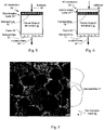
- 238000003917 TEM image Methods 0.000 description 1
- ATJFFYVFTNAWJD-UHFFFAOYSA-N Tin Chemical compound [Sn] ATJFFYVFTNAWJD-UHFFFAOYSA-N 0.000 description 1
- RTAQQCXQSZGOHL-UHFFFAOYSA-N Titanium Chemical compound [Ti] RTAQQCXQSZGOHL-UHFFFAOYSA-N 0.000 description 1
- 239000007983 Tris buffer Substances 0.000 description 1
- HCHKCACWOHOZIP-UHFFFAOYSA-N Zinc Chemical compound [Zn] HCHKCACWOHOZIP-UHFFFAOYSA-N 0.000 description 1
- QCWXUUIWCKQGHC-UHFFFAOYSA-N Zirconium Chemical compound [Zr] QCWXUUIWCKQGHC-UHFFFAOYSA-N 0.000 description 1
- NNLVGZFZQQXQNW-ADJNRHBOSA-N [(2r,3r,4s,5r,6s)-4,5-diacetyloxy-3-[(2s,3r,4s,5r,6r)-3,4,5-triacetyloxy-6-(acetyloxymethyl)oxan-2-yl]oxy-6-[(2r,3r,4s,5r,6s)-4,5,6-triacetyloxy-2-(acetyloxymethyl)oxan-3-yl]oxyoxan-2-yl]methyl acetate Chemical compound O([C@@H]1O[C@@H]([C@H]([C@H](OC(C)=O)[C@H]1OC(C)=O)O[C@H]1[C@@H]([C@@H](OC(C)=O)[C@H](OC(C)=O)[C@@H](COC(C)=O)O1)OC(C)=O)COC(=O)C)[C@@H]1[C@@H](COC(C)=O)O[C@@H](OC(C)=O)[C@H](OC(C)=O)[C@H]1OC(C)=O NNLVGZFZQQXQNW-ADJNRHBOSA-N 0.000 description 1
- FHKPLLOSJHHKNU-INIZCTEOSA-N [(3S)-3-[8-(1-ethyl-5-methylpyrazol-4-yl)-9-methylpurin-6-yl]oxypyrrolidin-1-yl]-(oxan-4-yl)methanone Chemical compound C(C)N1N=CC(=C1C)C=1N(C2=NC=NC(=C2N=1)O[C@@H]1CN(CC1)C(=O)C1CCOCC1)C FHKPLLOSJHHKNU-INIZCTEOSA-N 0.000 description 1
- GKXVJHDEWHKBFH-UHFFFAOYSA-N [2-(aminomethyl)phenyl]methanamine Chemical compound NCC1=CC=CC=C1CN GKXVJHDEWHKBFH-UHFFFAOYSA-N 0.000 description 1
- XHCLAFWTIXFWPH-UHFFFAOYSA-N [O-2].[O-2].[O-2].[O-2].[O-2].[V+5].[V+5] Chemical compound [O-2].[O-2].[O-2].[O-2].[O-2].[V+5].[V+5] XHCLAFWTIXFWPH-UHFFFAOYSA-N 0.000 description 1
- 150000001263 acyl chlorides Chemical class 0.000 description 1
- 230000002730 additional effect Effects 0.000 description 1
- 230000002776 aggregation Effects 0.000 description 1
- 238000004220 aggregation Methods 0.000 description 1
- 125000001931 aliphatic group Chemical group 0.000 description 1
- 229910001420 alkaline earth metal ion Inorganic materials 0.000 description 1
- 230000004075 alteration Effects 0.000 description 1
- 229910001586 aluminite Inorganic materials 0.000 description 1
- PNEYBMLMFCGWSK-UHFFFAOYSA-N aluminium oxide Inorganic materials [O-2].[O-2].[O-2].[Al+3].[Al+3] PNEYBMLMFCGWSK-UHFFFAOYSA-N 0.000 description 1
- VCNTUJWBXWAWEJ-UHFFFAOYSA-J aluminum;sodium;dicarbonate Chemical compound [Na+].[Al+3].[O-]C([O-])=O.[O-]C([O-])=O VCNTUJWBXWAWEJ-UHFFFAOYSA-J 0.000 description 1
- HPTYUNKZVDYXLP-UHFFFAOYSA-N aluminum;trihydroxy(trihydroxysilyloxy)silane;hydrate Chemical compound O.[Al].[Al].O[Si](O)(O)O[Si](O)(O)O HPTYUNKZVDYXLP-UHFFFAOYSA-N 0.000 description 1
- 229910052934 alunite Inorganic materials 0.000 description 1
- 239000010424 alunite Substances 0.000 description 1
- 150000001408 amides Chemical class 0.000 description 1
- 230000000844 anti-bacterial effect Effects 0.000 description 1
- 230000003373 anti-fouling effect Effects 0.000 description 1
- 230000000845 anti-microbial effect Effects 0.000 description 1
- 238000013459 approach Methods 0.000 description 1
- 239000002152 aqueous-organic solution Substances 0.000 description 1
- 229910052785 arsenic Inorganic materials 0.000 description 1
- 238000003556 assay Methods 0.000 description 1
- 230000004888 barrier function Effects 0.000 description 1
- 229910001570 bauxite Inorganic materials 0.000 description 1
- 239000011324 bead Substances 0.000 description 1
- RUOKPLVTMFHRJE-UHFFFAOYSA-N benzene-1,2,3-triamine Chemical compound NC1=CC=CC(N)=C1N RUOKPLVTMFHRJE-UHFFFAOYSA-N 0.000 description 1
- VXPZSDUXKPVHJC-UHFFFAOYSA-N benzene-1,2,3-tricarbonyl chloride Chemical compound ClC(=O)C1=CC=CC(C(Cl)=O)=C1C(Cl)=O VXPZSDUXKPVHJC-UHFFFAOYSA-N 0.000 description 1
- RPHKINMPYFJSCF-UHFFFAOYSA-N benzene-1,3,5-triamine Chemical compound NC1=CC(N)=CC(N)=C1 RPHKINMPYFJSCF-UHFFFAOYSA-N 0.000 description 1
- FDQSRULYDNDXQB-UHFFFAOYSA-N benzene-1,3-dicarbonyl chloride Chemical compound ClC(=O)C1=CC=CC(C(Cl)=O)=C1 FDQSRULYDNDXQB-UHFFFAOYSA-N 0.000 description 1
- 229910052790 beryllium Inorganic materials 0.000 description 1
- 230000003115 biocidal effect Effects 0.000 description 1
- 239000012620 biological material Substances 0.000 description 1
- 239000004305 biphenyl Chemical class 0.000 description 1
- 235000010290 biphenyl Nutrition 0.000 description 1
- 229910052797 bismuth Inorganic materials 0.000 description 1
- 229910001593 boehmite Inorganic materials 0.000 description 1
- 229910052796 boron Inorganic materials 0.000 description 1
- 150000003842 bromide salts Chemical class 0.000 description 1
- 125000000484 butyl group Chemical group [H]C([*])([H])C([H])([H])C([H])([H])C([H])([H])[H] 0.000 description 1
- VNSBYDPZHCQWNB-UHFFFAOYSA-N calcium;aluminum;dioxido(oxo)silane;sodium;hydrate Chemical compound O.[Na].[Al].[Ca+2].[O-][Si]([O-])=O VNSBYDPZHCQWNB-UHFFFAOYSA-N 0.000 description 1
- OYACROKNLOSFPA-UHFFFAOYSA-N calcium;dioxido(oxo)silane Chemical compound [Ca+2].[O-][Si]([O-])=O OYACROKNLOSFPA-UHFFFAOYSA-N 0.000 description 1
- 238000004364 calculation method Methods 0.000 description 1
- 239000011203 carbon fibre reinforced carbon Substances 0.000 description 1
- 239000011852 carbon nanoparticle Substances 0.000 description 1
- 239000007833 carbon precursor Substances 0.000 description 1
- 150000007942 carboxylates Chemical group 0.000 description 1
- 230000015556 catabolic process Effects 0.000 description 1
- 150000001768 cations Chemical class 0.000 description 1
- 230000030833 cell death Effects 0.000 description 1
- 210000002421 cell wall Anatomy 0.000 description 1
- 229920002301 cellulose acetate Polymers 0.000 description 1
- 238000005119 centrifugation Methods 0.000 description 1
- 239000002738 chelating agent Substances 0.000 description 1
- PBAYDYUZOSNJGU-UHFFFAOYSA-N chelidonic acid Natural products OC(=O)C1=CC(=O)C=C(C(O)=O)O1 PBAYDYUZOSNJGU-UHFFFAOYSA-N 0.000 description 1
- 238000010382 chemical cross-linking Methods 0.000 description 1
- 239000000460 chlorine Substances 0.000 description 1
- 229910052801 chlorine Inorganic materials 0.000 description 1
- 150000001805 chlorine compounds Chemical group 0.000 description 1
- 229910052804 chromium Inorganic materials 0.000 description 1
- 238000003776 cleavage reaction Methods 0.000 description 1
- 229910052681 coesite Inorganic materials 0.000 description 1
- 239000000084 colloidal system Substances 0.000 description 1
- 238000004891 communication Methods 0.000 description 1
- 238000010668 complexation reaction Methods 0.000 description 1
- 229910052593 corundum Inorganic materials 0.000 description 1
- 229910052906 cristobalite Inorganic materials 0.000 description 1
- 238000004132 cross linking Methods 0.000 description 1
- 239000003431 cross linking reagent Substances 0.000 description 1
- 229910001610 cryolite Inorganic materials 0.000 description 1
- 229910001647 dawsonite Inorganic materials 0.000 description 1
- 238000006731 degradation reaction Methods 0.000 description 1
- 230000000593 degrading effect Effects 0.000 description 1
- 239000002274 desiccant Substances 0.000 description 1
- 238000013461 design Methods 0.000 description 1
- GUJOJGAPFQRJSV-UHFFFAOYSA-N dialuminum;dioxosilane;oxygen(2-);hydrate Chemical compound O.[O-2].[O-2].[O-2].[Al+3].[Al+3].O=[Si]=O.O=[Si]=O.O=[Si]=O.O=[Si]=O GUJOJGAPFQRJSV-UHFFFAOYSA-N 0.000 description 1
- JYIMWRSJCRRYNK-UHFFFAOYSA-N dialuminum;disodium;oxygen(2-);silicon(4+);hydrate Chemical compound O.[O-2].[O-2].[O-2].[O-2].[O-2].[O-2].[Na+].[Na+].[Al+3].[Al+3].[Si+4] JYIMWRSJCRRYNK-UHFFFAOYSA-N 0.000 description 1
- GDVKFRBCXAPAQJ-UHFFFAOYSA-A dialuminum;hexamagnesium;carbonate;hexadecahydroxide Chemical compound [OH-].[OH-].[OH-].[OH-].[OH-].[OH-].[OH-].[OH-].[OH-].[OH-].[OH-].[OH-].[OH-].[OH-].[OH-].[OH-].[Mg+2].[Mg+2].[Mg+2].[Mg+2].[Mg+2].[Mg+2].[Al+3].[Al+3].[O-]C([O-])=O GDVKFRBCXAPAQJ-UHFFFAOYSA-A 0.000 description 1
- 229910001648 diaspore Inorganic materials 0.000 description 1
- 229910001649 dickite Inorganic materials 0.000 description 1
- 238000003618 dip coating Methods 0.000 description 1
- 238000009826 distribution Methods 0.000 description 1
- 230000001614 effect on membrane Effects 0.000 description 1
- 125000001495 ethyl group Chemical group [H]C([H])([H])C([H])([H])* 0.000 description 1
- 239000012527 feed solution Substances 0.000 description 1
- 229910001657 ferrierite group Inorganic materials 0.000 description 1
- 238000009292 forward osmosis Methods 0.000 description 1
- 229910003472 fullerene Inorganic materials 0.000 description 1
- 229910052733 gallium Inorganic materials 0.000 description 1
- 229910052732 germanium Inorganic materials 0.000 description 1
- 229910001679 gibbsite Inorganic materials 0.000 description 1
- PCHJSUWPFVWCPO-UHFFFAOYSA-N gold Chemical compound [Au] PCHJSUWPFVWCPO-UHFFFAOYSA-N 0.000 description 1
- 229910052737 gold Inorganic materials 0.000 description 1
- 239000010931 gold Substances 0.000 description 1
- 229910002804 graphite Inorganic materials 0.000 description 1
- 239000010439 graphite Substances 0.000 description 1
- 229910052621 halloysite Inorganic materials 0.000 description 1
- 238000013007 heat curing Methods 0.000 description 1
- 238000000265 homogenisation Methods 0.000 description 1
- 229920001477 hydrophilic polymer Polymers 0.000 description 1
- 230000005660 hydrophilic surface Effects 0.000 description 1
- 230000002706 hydrostatic effect Effects 0.000 description 1
- 229910001701 hydrotalcite Inorganic materials 0.000 description 1
- 229960001545 hydrotalcite Drugs 0.000 description 1
- FAHBNUUHRFUEAI-UHFFFAOYSA-M hydroxidooxidoaluminium Chemical compound O[Al]=O FAHBNUUHRFUEAI-UHFFFAOYSA-M 0.000 description 1
- 229910052900 illite Inorganic materials 0.000 description 1
- 229910052738 indium Inorganic materials 0.000 description 1
- APFVFJFRJDLVQX-UHFFFAOYSA-N indium atom Chemical compound [In] APFVFJFRJDLVQX-UHFFFAOYSA-N 0.000 description 1
- PJXISJQVUVHSOJ-UHFFFAOYSA-N indium(III) oxide Inorganic materials [O-2].[O-2].[O-2].[In+3].[In+3] PJXISJQVUVHSOJ-UHFFFAOYSA-N 0.000 description 1
- 229910001387 inorganic aluminate Inorganic materials 0.000 description 1
- 229910052909 inorganic silicate Inorganic materials 0.000 description 1
- 150000004694 iodide salts Chemical class 0.000 description 1
- 238000002955 isolation Methods 0.000 description 1
- 229910001705 kalinite Inorganic materials 0.000 description 1
- NLYAJNPCOHFWQQ-UHFFFAOYSA-N kaolin Chemical compound O.O.O=[Al]O[Si](=O)O[Si](=O)O[Al]=O NLYAJNPCOHFWQQ-UHFFFAOYSA-N 0.000 description 1
- 229910052622 kaolinite Inorganic materials 0.000 description 1
- 238000000608 laser ablation Methods 0.000 description 1
- 238000013532 laser treatment Methods 0.000 description 1
- RVMQNIPAIQIBSC-UHFFFAOYSA-N lead;2,2,2-trifluoroacetic acid Chemical compound [Pb].OC(=O)C(F)(F)F RVMQNIPAIQIBSC-UHFFFAOYSA-N 0.000 description 1
- 239000003446 ligand Substances 0.000 description 1
- 229910052744 lithium Inorganic materials 0.000 description 1
- 229920002521 macromolecule Polymers 0.000 description 1
- 229910052748 manganese Inorganic materials 0.000 description 1
- 239000011572 manganese Substances 0.000 description 1
- 238000005259 measurement Methods 0.000 description 1
- 230000007246 mechanism Effects 0.000 description 1
- 230000001404 mediated effect Effects 0.000 description 1
- 229910001721 mellite Inorganic materials 0.000 description 1
- 239000012621 metal-organic framework Substances 0.000 description 1
- 150000002739 metals Chemical class 0.000 description 1
- 238000001471 micro-filtration Methods 0.000 description 1
- 239000011859 microparticle Substances 0.000 description 1
- 239000004941 mixed matrix membrane Substances 0.000 description 1
- 238000002156 mixing Methods 0.000 description 1
- 229910052961 molybdenite Inorganic materials 0.000 description 1
- CWQXQMHSOZUFJS-UHFFFAOYSA-N molybdenum disulfide Chemical compound S=[Mo]=S CWQXQMHSOZUFJS-UHFFFAOYSA-N 0.000 description 1
- 229910052982 molybdenum disulfide Inorganic materials 0.000 description 1
- 229910052901 montmorillonite Inorganic materials 0.000 description 1
- 229910052680 mordenite Inorganic materials 0.000 description 1
- 239000007783 nanoporous material Substances 0.000 description 1
- UFWIBTONFRDIAS-UHFFFAOYSA-N naphthalene-acid Natural products C1=CC=CC2=CC=CC=C21 UFWIBTONFRDIAS-UHFFFAOYSA-N 0.000 description 1
- 150000002790 naphthalenes Chemical class 0.000 description 1
- 229910001811 natroalunite Inorganic materials 0.000 description 1
- 230000007935 neutral effect Effects 0.000 description 1
- VGIBGUSAECPPNB-UHFFFAOYSA-L nonaaluminum;magnesium;tripotassium;1,3-dioxido-2,4,5-trioxa-1,3-disilabicyclo[1.1.1]pentane;iron(2+);oxygen(2-);fluoride;hydroxide Chemical compound [OH-].[O-2].[O-2].[O-2].[O-2].[O-2].[F-].[Mg+2].[Al+3].[Al+3].[Al+3].[Al+3].[Al+3].[Al+3].[Al+3].[Al+3].[Al+3].[K+].[K+].[K+].[Fe+2].O1[Si]2([O-])O[Si]1([O-])O2.O1[Si]2([O-])O[Si]1([O-])O2.O1[Si]2([O-])O[Si]1([O-])O2.O1[Si]2([O-])O[Si]1([O-])O2.O1[Si]2([O-])O[Si]1([O-])O2.O1[Si]2([O-])O[Si]1([O-])O2.O1[Si]2([O-])O[Si]1([O-])O2 VGIBGUSAECPPNB-UHFFFAOYSA-L 0.000 description 1
- 229910052755 nonmetal Inorganic materials 0.000 description 1
- 229910000273 nontronite Inorganic materials 0.000 description 1
- 238000000655 nuclear magnetic resonance spectrum Methods 0.000 description 1
- 239000012038 nucleophile Substances 0.000 description 1
- 150000002892 organic cations Chemical class 0.000 description 1
- 150000002902 organometallic compounds Chemical class 0.000 description 1
- 125000004430 oxygen atom Chemical group O* 0.000 description 1
- MKTRXTLKNXLULX-UHFFFAOYSA-P pentacalcium;dioxido(oxo)silane;hydron;tetrahydrate Chemical compound [H+].[H+].O.O.O.O.[Ca+2].[Ca+2].[Ca+2].[Ca+2].[Ca+2].[O-][Si]([O-])=O.[O-][Si]([O-])=O.[O-][Si]([O-])=O.[O-][Si]([O-])=O.[O-][Si]([O-])=O.[O-][Si]([O-])=O MKTRXTLKNXLULX-UHFFFAOYSA-P 0.000 description 1
- PPPLOTGLKDTASM-UHFFFAOYSA-A pentasodium;pentafluoroaluminum(2-);tetrafluoroalumanuide Chemical compound [F-].[F-].[F-].[F-].[F-].[F-].[F-].[F-].[F-].[F-].[F-].[F-].[F-].[F-].[Na+].[Na+].[Na+].[Na+].[Na+].[Al+3].[Al+3].[Al+3] PPPLOTGLKDTASM-UHFFFAOYSA-A 0.000 description 1
- 239000012466 permeate Substances 0.000 description 1
- 235000021317 phosphate Nutrition 0.000 description 1
- 150000003013 phosphoric acid derivatives Chemical class 0.000 description 1
- 229920002239 polyacrylonitrile Polymers 0.000 description 1
- 229920006393 polyether sulfone Polymers 0.000 description 1
- 229920005594 polymer fiber Polymers 0.000 description 1
- 229920005597 polymer membrane Polymers 0.000 description 1
- 229920001155 polypropylene Polymers 0.000 description 1
- 229920002451 polyvinyl alcohol Polymers 0.000 description 1
- 235000019422 polyvinyl alcohol Nutrition 0.000 description 1
- GNHOJBNSNUXZQA-UHFFFAOYSA-J potassium aluminium sulfate dodecahydrate Chemical compound O.O.O.O.O.O.O.O.O.O.O.O.[Al+3].[K+].[O-]S([O-])(=O)=O.[O-]S([O-])(=O)=O GNHOJBNSNUXZQA-UHFFFAOYSA-J 0.000 description 1
- 239000002244 precipitate Substances 0.000 description 1
- 238000001556 precipitation Methods 0.000 description 1
- 125000002924 primary amino group Chemical group [H]N([H])* 0.000 description 1
- 150000003142 primary aromatic amines Chemical class 0.000 description 1
- 125000001436 propyl group Chemical group [H]C([*])([H])C([H])([H])C([H])([H])[H] 0.000 description 1
- AOHJOMMDDJHIJH-UHFFFAOYSA-N propylenediamine Chemical compound CC(N)CN AOHJOMMDDJHIJH-UHFFFAOYSA-N 0.000 description 1
- 230000005855 radiation Effects 0.000 description 1
- 229910052761 rare earth metal Inorganic materials 0.000 description 1
- 150000002910 rare earth metals Chemical class 0.000 description 1
- 238000010992 reflux Methods 0.000 description 1
- 230000003014 reinforcing effect Effects 0.000 description 1
- 229910000275 saponite Inorganic materials 0.000 description 1
- 230000007017 scission Effects 0.000 description 1
- 238000006748 scratching Methods 0.000 description 1
- 230000002393 scratching effect Effects 0.000 description 1
- 150000005619 secondary aliphatic amines Chemical class 0.000 description 1
- 125000000467 secondary amino group Chemical group [H]N([*:1])[*:2] 0.000 description 1
- 238000000926 separation method Methods 0.000 description 1
- 150000004760 silicates Chemical class 0.000 description 1
- 229910052710 silicon Inorganic materials 0.000 description 1
- 239000010703 silicon Substances 0.000 description 1
- 235000012239 silicon dioxide Nutrition 0.000 description 1
- 229910052709 silver Inorganic materials 0.000 description 1
- 239000004332 silver Substances 0.000 description 1
- 238000007764 slot die coating Methods 0.000 description 1
- SUKJFIGYRHOWBL-UHFFFAOYSA-N sodium hypochlorite Chemical compound [Na+].Cl[O-] SUKJFIGYRHOWBL-UHFFFAOYSA-N 0.000 description 1
- 239000007790 solid phase Substances 0.000 description 1
- 238000001179 sorption measurement Methods 0.000 description 1
- 229910052682 stishovite Inorganic materials 0.000 description 1
- 239000000126 substance Substances 0.000 description 1
- 238000006467 substitution reaction Methods 0.000 description 1
- 239000000758 substrate Substances 0.000 description 1
- LXEJRKJRKIFVNY-UHFFFAOYSA-N terephthaloyl chloride Chemical compound ClC(=O)C1=CC=C(C(Cl)=O)C=C1 LXEJRKJRKIFVNY-UHFFFAOYSA-N 0.000 description 1
- PQDFWSNINWMLDU-UHFFFAOYSA-B tetraaluminum;decahydroxide;sulfate;pentahydrate Chemical compound O.O.O.O.O.[OH-].[OH-].[OH-].[OH-].[OH-].[OH-].[OH-].[OH-].[OH-].[OH-].[Al+3].[Al+3].[Al+3].[Al+3].[O-]S([O-])(=O)=O PQDFWSNINWMLDU-UHFFFAOYSA-B 0.000 description 1
- 125000003698 tetramethyl group Chemical group [H]C([H])([H])* 0.000 description 1
- 229910001770 thomsenolite Inorganic materials 0.000 description 1
- 229910052718 tin Inorganic materials 0.000 description 1
- 239000011135 tin Substances 0.000 description 1
- 230000001052 transient effect Effects 0.000 description 1
- 238000004627 transmission electron microscopy Methods 0.000 description 1
- KPZTWMNLAFDTGF-UHFFFAOYSA-D trialuminum;potassium;hexahydroxide;disulfate Chemical compound [OH-].[OH-].[OH-].[OH-].[OH-].[OH-].[Al+3].[Al+3].[Al+3].[K+].[O-]S([O-])(=O)=O.[O-]S([O-])(=O)=O KPZTWMNLAFDTGF-UHFFFAOYSA-D 0.000 description 1
- 229910052905 tridymite Inorganic materials 0.000 description 1
- ITRNXVSDJBHYNJ-UHFFFAOYSA-N tungsten disulfide Chemical compound S=[W]=S ITRNXVSDJBHYNJ-UHFFFAOYSA-N 0.000 description 1
- 238000000108 ultra-filtration Methods 0.000 description 1
- 229910001935 vanadium oxide Inorganic materials 0.000 description 1
- 239000012808 vapor phase Substances 0.000 description 1
- 230000000007 visual effect Effects 0.000 description 1
- 229910001789 woodhouseite Inorganic materials 0.000 description 1
- 229910001845 yogo sapphire Inorganic materials 0.000 description 1
- 239000012690 zeolite precursor Substances 0.000 description 1
- XLOMVQKBTHCTTD-UHFFFAOYSA-N zinc oxide Inorganic materials [Zn]=O XLOMVQKBTHCTTD-UHFFFAOYSA-N 0.000 description 1
- 229910052726 zirconium Inorganic materials 0.000 description 1
Images


Classifications
-
- B—PERFORMING OPERATIONS; TRANSPORTING
- B01—PHYSICAL OR CHEMICAL PROCESSES OR APPARATUS IN GENERAL
- B01D—SEPARATION
- B01D69/00—Semi-permeable membranes for separation processes or apparatus characterised by their form, structure or properties; Manufacturing processes specially adapted therefor
- B01D69/12—Composite membranes; Ultra-thin membranes
- B01D69/125—In situ manufacturing by polymerisation, polycondensation, cross-linking or chemical reaction
- B01D69/1251—In situ manufacturing by polymerisation, polycondensation, cross-linking or chemical reaction by interfacial polymerisation
-
- B—PERFORMING OPERATIONS; TRANSPORTING
- B01—PHYSICAL OR CHEMICAL PROCESSES OR APPARATUS IN GENERAL
- B01D—SEPARATION
- B01D61/00—Processes of separation using semi-permeable membranes, e.g. dialysis, osmosis or ultrafiltration; Apparatus, accessories or auxiliary operations specially adapted therefor
- B01D61/02—Reverse osmosis; Hyperfiltration ; Nanofiltration
- B01D61/025—Reverse osmosis; Hyperfiltration
-
- B—PERFORMING OPERATIONS; TRANSPORTING
- B01—PHYSICAL OR CHEMICAL PROCESSES OR APPARATUS IN GENERAL
- B01D—SEPARATION
- B01D67/00—Processes specially adapted for manufacturing semi-permeable membranes for separation processes or apparatus
- B01D67/0079—Manufacture of membranes comprising organic and inorganic components
- B01D67/00793—Dispersing a component, e.g. as particles or powder, in another component
-
- B—PERFORMING OPERATIONS; TRANSPORTING
- B01—PHYSICAL OR CHEMICAL PROCESSES OR APPARATUS IN GENERAL
- B01D—SEPARATION
- B01D69/00—Semi-permeable membranes for separation processes or apparatus characterised by their form, structure or properties; Manufacturing processes specially adapted therefor
- B01D69/10—Supported membranes; Membrane supports
-
- B—PERFORMING OPERATIONS; TRANSPORTING
- B01—PHYSICAL OR CHEMICAL PROCESSES OR APPARATUS IN GENERAL
- B01D—SEPARATION
- B01D69/00—Semi-permeable membranes for separation processes or apparatus characterised by their form, structure or properties; Manufacturing processes specially adapted therefor
- B01D69/14—Dynamic membranes
- B01D69/141—Heterogeneous membranes, e.g. containing dispersed material; Mixed matrix membranes
-
- B—PERFORMING OPERATIONS; TRANSPORTING
- B01—PHYSICAL OR CHEMICAL PROCESSES OR APPARATUS IN GENERAL
- B01D—SEPARATION
- B01D71/00—Semi-permeable membranes for separation processes or apparatus characterised by the material; Manufacturing processes specially adapted therefor
- B01D71/02—Inorganic material
- B01D71/0213—Silicon
-
- B—PERFORMING OPERATIONS; TRANSPORTING
- B01—PHYSICAL OR CHEMICAL PROCESSES OR APPARATUS IN GENERAL
- B01D—SEPARATION
- B01D71/00—Semi-permeable membranes for separation processes or apparatus characterised by the material; Manufacturing processes specially adapted therefor
- B01D71/02—Inorganic material
- B01D71/028—Molecular sieves
- B01D71/0281—Zeolites
-
- B—PERFORMING OPERATIONS; TRANSPORTING
- B01—PHYSICAL OR CHEMICAL PROCESSES OR APPARATUS IN GENERAL
- B01D—SEPARATION
- B01D2325/00—Details relating to properties of membranes
- B01D2325/48—Antimicrobial properties
-
- B—PERFORMING OPERATIONS; TRANSPORTING
- B01—PHYSICAL OR CHEMICAL PROCESSES OR APPARATUS IN GENERAL
- B01D—SEPARATION
- B01D71/00—Semi-permeable membranes for separation processes or apparatus characterised by the material; Manufacturing processes specially adapted therefor
- B01D71/02—Inorganic material
- B01D71/028—Molecular sieves
-
- B—PERFORMING OPERATIONS; TRANSPORTING
- B01—PHYSICAL OR CHEMICAL PROCESSES OR APPARATUS IN GENERAL
- B01D—SEPARATION
- B01D71/00—Semi-permeable membranes for separation processes or apparatus characterised by the material; Manufacturing processes specially adapted therefor
- B01D71/06—Organic material
- B01D71/56—Polyamides, e.g. polyester-amides
-
- Y—GENERAL TAGGING OF NEW TECHNOLOGICAL DEVELOPMENTS; GENERAL TAGGING OF CROSS-SECTIONAL TECHNOLOGIES SPANNING OVER SEVERAL SECTIONS OF THE IPC; TECHNICAL SUBJECTS COVERED BY FORMER USPC CROSS-REFERENCE ART COLLECTIONS [XRACs] AND DIGESTS
- Y02—TECHNOLOGIES OR APPLICATIONS FOR MITIGATION OR ADAPTATION AGAINST CLIMATE CHANGE
- Y02A—TECHNOLOGIES FOR ADAPTATION TO CLIMATE CHANGE
- Y02A20/00—Water conservation; Efficient water supply; Efficient water use
- Y02A20/124—Water desalination
- Y02A20/131—Reverse-osmosis
Definitions
- the present invention relates to a highly permeable reverse osmosis (RO) mebrane and an interfacial polymerization method for preparing a highly permeable reverse osmosis (RO) membrane.
- RO reverse osmosis
- Reverse osmosis membranes made by interfacial polymerization of a monomer in a nonpolar (e.g. organic) phase together with a monomer in a polar (e.g. aqueous) phase on a porous support membrane are known as TFC membranes and are used where flux and substantial rejection characteristics are required, for example in the purification of water.
- TFC membranes Various materials have been added to TFC membranes to increase flux without reducing rejection characteristics and have met with limited success.
- Such membranes are also subject to fouling resulting in reduced flux as contaminants, for example from the brackish or seawater to be purified, build up on the surface of the discrimination layer of the TFC membrane.
- US 5,371,166 A and WO 98/45499 A1 disclose a composition for preparing a discrimination layer of a RO membrane, comprising: a monomer for an interfacial polymerization; and a molecular additive compound, wherein the molecular additive compound is a ⁇ -diketonate complex including an alkaline earth metal.
- WO01/78882 A2 discloses the preparation of reverse osmosis polyamide membranes prepared by interfacial polymerization. Disclosed is the addition of a metal complex to the polyfunctional acid halide solution in order to improve flux. Exemplarily, two ⁇ -diketones, acetyl acetonate, tetramethyl-3,5-heptane dionate complexed with Fe, Co, Cr are mentioned.
- WO 2006/098872 A2 discloses the use of zeolite nanoparticles for flux improvement of a polyamide membrane for reverse osmosis.
- the present invention provides a highly permeable reverse osmosis (RO) membrane produced by an interfacial polymerization process, comprising:
- the present invention also provides an interfacial polymerization method for preparing a highly permeable reverse osmosis (RO) membrane, comprising:
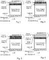
- RO membrane 10 is synthesized using a interfacial polymerization process on a porous support membrane 12. Two immiscible solvents are used, so that a monomer in one solvent reacts with a monomer in the other solvent. The reactions are very fast and relatively high molecular weights are obtained.
- fabric layer 20 may have nanoparticles 22 incorporated for added strength.
- Fabric layer 20 is preferably permeable to water, flat, and without stray fibers that could penetrate support 12 or thin film discrimination layer 24. It should be thin to decrease cost and to maximize membrane area, strong against extension, and mechanically resistant to deformation at high pressures. By adding nanoparticles 22 to the polymer fibers of fabric 20, more mechanically robust backings may be created that allow thinner, cheaper, and/or tougher supports to be manufactured.
- aqueous phase layer 14 is shown with nanoparticles 16 dispersed therein on an upper surface of support membrane 12, and organic phase layer 18 interacts with aqueous layer 14.
- the interface between these layers is where the polymerization occurs.
- Nanoparticles may be selected for their ability to release metal species such as alkaline earth or aluminum ions. Such particles may be dispersed within either the aqueous layer 14 or the organic phase layer 18, or both. Additional nanoparticles may also be present to impact surface properties or further increase performance, for example to improve fouling resistance. Nanoparticles 22 may be the same or different from nanoparticles 16. Metal ions 16 may be dissolved within either the aqueous layer 14, as shown in Fig. 10 , or the organic phase layer 18, as shown in Fig. 11 , or in both layers. Metal ions 16 may be dissolved within the aqueous layer 14, as shown in Fig. 13 .
- Nanoparticles 16 By dispersing aluminum releasing nanoparticles 16 in the aqueous or polar solvent 14 and/or organic phase layer 18 before interfacial polymerization, increased flux is often observed, especially when nanoparticles 16 are processed to enhance solubility of metal ions. Nanoparticles in solution may release aluminum before the polymerization reaction occurs to aqueous solution 14 or organic solution 18.
- the dissolved metal ions are thought to affect the polymerization reaction and ultimately membrane structure leading to improved performance. It is thought that the dissolved metal ions may serve as a template to guide polymerization leaving spaces or channels for increased water transport.
- nanoparticles 16 selected to release soluble metal species to introduce metal ions 17 into aqueous layer 14, during fabrication may be dispersed within or on porous support membrane 12. Nanoparticles 16 may also be introduced into aqueous layer 14 or organic phase layer 18 or both to introduce additional metal ions 17 into aqueous layer 14 during fabrication. Additional nanoparticles 17 may also be present to impact surface properties or further increase performance of membrane 10.
- the interfacial polymerization process at least one of solutions a) and b) contains nanoparticles that release at least 1 ppm of a soluble metal species per 5% (w/w) nanoparticles, based on the weight of the mixture, and wherein said nanoparticles have been processed to maximize the amount of said soluble metal species contributed to the interfacial polymerization mixture.
- RO membranes may be fabricated in which nanoparticles are included in the porous support membrane to release soluble metal ions for the interfacial polymerization process and/or improve flux flow decline by, perhaps, resisting compaction of the support membranes during reverse osmosis.
- the nanoparticles may be selected based on their ability to release 1 ppm or more of soluble metal species into the water contained in the support membrane. It may be advantageous to store the support membrane, for example for up to one hour, before interfacial polymerization on the support membrane between aqueous and organic phase solutions. It may also be advantageous to form the discrimination layer by contacting the aqueous phase solution to the organic phase solution on the support membrane for at least 10 seconds, preferably 2 minutes and more preferably 5 minutes after the organic phase solution is applied.
- Membrane 12 is typically a polymeric microporous support membrane which in turn is often supported by nonwoven or woven fabrics, such as fabric 20, for mechanical strength.
- Support membranes 12 are typically 25-250 microns in thickness and have been found to have the smallest pores located very near the upper surface. Porosity at the surface is often low, for instance from 5-15%, of the total surface area.
- Nanoparticles 16 may be incorporated into support membrane 12 by including nanoparticles 16 with casting solution 13 used to prepare support membrane 12, or by including nanoparticles 16 within the nonsolvent, e.g. DI water, used to induce phase inversion during fabrication of support membrane 12.
- nonsolvent e.g. DI water
- the addition of nanoparticles 16 to support membrane 12 may also serve to increase or maintain flux, or at least reduce the decline over time of the flux, of purified water 28 through membrane 10 from reverse osmosis of saltwater 26.
- the application of hydrostatic pressures via saltwater 26 to conventional thin film composite membranes (TFC) is known to cause a reduction of membrane permeability, probably due to compaction of support membrane 12.
- TFC thin film composite membranes
- Nanoparticles in solution in aqueous solution 14 or organic solution 18 may release metal ions 17 before the polymerization.
- Dissolved metal ions 17 are thought to affect the polymerization reaction and ultimately membrane structure leading to improved performance. It is thought that the dissolved metal ions 17 may serve as a template to guide polymerization leaving spaces or channels for increased water transport.
- porous support membrane 12 including nanoparticles 16 dispersed therein, and/or on the surface thereof can be immersed in an aqueous solution, such as aqueous phase 14, containing a first reactant (e.g., 1,3-diaminobenzene or "MPD" monomer) to release soluble metal ions 17 therein.
- a first reactant e.g., 1,3-diaminobenzene or "MPD" monomer
- Support membrane 12 can then be put in contact with an organic solution, such as organic phase 18, containing a second reactant (e.g., trimesoyl chloride or "TMC" initiator).
- TMC trimesoyl chloride
- the organic or apolar liquid is immiscible with the polar or aqueous liquid, so that the reaction occurs at the interface between the two solutions, e.g. between aqueous and organic phases 14,18 to form a dense polymer layer on surface of support membrane 12.
- Suitable nanoparticles 16 for dispersion in support membrane 12 as described above include those selected for their ability to release alkaline earth metals, or other metal species, into organic phase 14 during the interfacial polymerization reaction, especially when nanoparticles 16 are processed to enhance solubility of metal ions such as alkaline earth metals 17.
- Nanoparticles 16 may be selected to release metal ions 17 which may enter the water or other solvent contained within or on support membrane 12.
- the amount of metal ions 17 available for the interfacial polymerization of aqueous phase 14 and organic phase 18 may in some cases be increased by storing support membrane 12, for example in roll form, for a suitable time period such as at least one hour before fabrication of RO membrane 10.
- metal ions 17 may be important to allow sufficient time for metal ions 17 to diffuse from support membrane 12 into aqueous phase 14 before or during interfacial polymerization.
- a time of between 2 seconds and 5 minutes, and preferably between 10 seconds and 2 minutes is currently believed to be suitable for such diffusion so that metal ions 17 from nanoparticles 16 impacts formation of discrimination layer 24 and improves performance of RO membrane for example by increasing water flux therethrough for the same applied pressure.
- Sonication processing nanoparticles 16 may include immersing a sonic probe directly into casting solution 13 from which support membrane 12 is formed or into organic or aqueous phases 14 and/or 18 and/or placing solutions with nanoparticles 16 in a vessel and immersing the vessel in a sonic bath. Solutions are subjected to sufficient sonic energy from 10 to 60 minutes to aid in the release of metal species, such as alkaline earth metal ions 17, into the solution. After sonication, the solution contains additional metal species. Additional sonication time may release additional metal species up to some limit equilibrium.
- Processing of selected nanoparticles 16 may also be accomplished using shear, cavitation, and impact forces generated by 1 to 60 minutes in a Microfluidizer (a trademark of the Microfluidics Corp.). After processing, the solution contains additional metal species that were dissolved from nanoparticles 16.
- Processing of selected nanoparticles 16 may be also accomplished using a solution containing nanoparticles 16 in a vessel with a stir bar and using a stir plate to propel the stir bar in the solution or alternatively using a motorized propeller to stir the solution or alternatively using a lab tray shaker. Stirring or shaking is most effective for nanoparticles that have been selected for high solubility in either the aqueous or the organic phases 14, 18.
- Processing of the selected nanoparticles 16 may be accomplished using a solution containing nanoparticles 16 in a vessel and adjusting the pH either lower than about 6 and more preferably less than about 5 for at least 30 seconds, to a pH greater than about 8 and more preferably greater than about 9 for at least 30 seconds. Whether pH is adjusted higher than about 8 or lower than about 6 may dependent on the solubility characteristics of the specific type of nanoparticle 16.
- molecular additive encompasses a wide range of additives.
- preferred concentrations of molecular additives are from 0.0001% (weight percent equivalent of 1 ppm) to 5% by weight and more preferred from 0.05% to 1% into aqueous layer 14.
- Processing may enhance nanoparticle dissolution, or other techniques for adding molecular additives to assist in achieving the desired concentrations of molecular additives 17 in solution.
- Processed nanoparticles or other carries may have been broken or partially dissolved using shear, cavitation, or impact forces to maximize said soluble metal species contributed to the interfacial polymerization mixture, including a microfluidizer apparatus.
- the nanoparticles or other relatively insoluble carriers may have been calcined for at least 1 hour at 200°C or more.
- the processed carriers can have been shaken in aqueous solution on a shaker table for at least 1 minute.
- Carriers may have been processed by subjecting them to sonic energy in a vessel having a sonic probe within a solution, said energy sufficient to increase the soluble metal species or other molecular additives contributed by the processed carriers to the interfacial polymerization mixture, e.g., in a vessel suspended in a sonic bath for at least 5 minutes.
- the nanoparticles or other relatively insoluble carriers may have been processed in a solution at a pH lower than about 6 for at least 30 seconds or at a pH lower than about 5 for at least 30 seconds.
- the nanoparticles or other relatively insoluble carriers may have been processed in a solution at a pH greater than about 8 for at least 30 seconds or in a solution at a pH greater than about 9 for at least 30 seconds.
- Nanoparticles or other relatively insoluble carriers may have been processed with heat in a solution for at least 5 minutes at a temperature of 40°C or more.
- Nanoparticles or other relatively insoluble carriers may have been processed with chelating agents in solution to bind soluble metal species or other molecular additives.
- Zeolites and other inorganic mineral compounds may also be further selected for use as nanoparticles 16 to release molecular additives 17 based on the degree of crystallization the nanoparticles 16.
- Amorphous portions of nanoparticles 16 are typically more soluble than crystalline portions of the nanoparticle and processing can increase solubility.
- the amount of crystalline material can be determined through several techniques including x-ray crystallography.
- nanoparticles or other insoluble carriers 16 may be included in organic phase or layer 18, both aqueous layer 14 and organic layer 18, and/or also or only in a layer between aqueous phase 14 and support membrane 12 for example in water solution 15 in liquid communication with both aqueous layer 14 and the water wetted surface of support membrane 12. Nanoparticles or other relatively insoluble carriers 16 may in fact be in the water wetted surface of support membrane 12 whether or not included in the aqueous layer 14 or organic layer 18.
- Support membrane 12 is typically a polymeric microporous support membrane, which in turn is often supported by non-woven or woven fabrics, such as fabric 20, for mechanical strength.
- Support membrane 12 may conventionally be made from polysulfone or other suitably porous membranes, such as polyethersulfone, poly(ether sulfone ketone), poly(ether ethyl ketone), poly(phthalazinone ether sulfone ketone), polyacrylonitrile, polypropylene, cellulose acetate, cellulose diacetate, or cellulose triacetate.
- These microporous support membranes 12 are typically 25-250 microns in thickness and may have the smallest pores located very near the upper surface. Porosity at the surface may be low, for instance from 5-15% of the total surface area.
- the preparation of support membrane 12 may begin with the addition of N-methyl pyrrolidone (NMP) solvent (Acros Organics, USA) to a polysulfone polymer (M,-26,000 from Aldrich, USA) in transparent bead form in airtight glass bottles.
- NMP N-methyl pyrrolidone
- M polysulfone polymer
- DMF dimethylformamide
- Nanoparticles 16 may be dispersed in the NMP before its addition to the polysulfone polymer.
- the solution may then be agitated for several hours until complete dissolution is achieved, forming the dope or casting solution 13.
- Casting solution 13 may then be cast or spread over non-woven fabric 20 attached to glass plate 15 via a knife-edge.
- Glass plate 15 may then be immediately immersed into demineralized water, which had preferably been maintained at the desired temperature. Immediately, phase inversion begins and after several minutes, non-woven support fabric 20 supporting polysulfone membrane 12 may be separated from glass plate 15. Membrane 12 is then washed thoroughly with deionized water and stored in cold conditions until used. In a continuous coating process, glass plate 15 would not be required.
- Nanoparticles such as zeolites, particularly LTA may be added to support membrane 12 during processing to improve flux for reverse osmosis by, perhaps, improving porosity e.g. at the surface of support membrane 12 and/or by making membrane 12 more resistant to compaction.
- nanoparticles or other relatively insoluble carriers 16 may be added to aqueous phase 14 to improve RO membrane characteristics such as flux without reducing rejection as much as adding nanoparticles 16 to the organic phase 18. Nanoparticles or other relatively insoluble carriers 16 may similarly be included in a layer between support membrane 12 and discrimination layer 24 as shown below in Fig. 6 .
- the rejection may be at least 99.5% and the flux is at least 11580, 13510 or 15440 liter per sqare meter per day (LMD) (30, 35 or 40 GFD).
- Nanoparticles or other relatively insoluble carriers 16 may include a metallic species such as gold, silver, copper, zinc, titanium, iron, aluminum, zirconium, indium, tin, magnesium, or calcium or an alloy thereof or an oxide thereof or a mixture thereof. They can also be a nonmetallic species such as Si 3 N 4 , SiC, BN, B 4 C, or TiC or an alloy thereof or a mixture thereof. They can be a carbon-based species such as graphite, carbon glass, a carbon cluster of at least C 2 , buckminsterfullerene, a higher fullerene, a carbon nanotube, a carbon nanoparticle, or a mixture thereof.
- a metallic species such as gold, silver, copper, zinc, titanium, iron, aluminum, zirconium, indium, tin, magnesium, or calcium or an alloy thereof or an oxide thereof or a mixture thereof. They can also be a nonmetallic species such as Si 3 N 4 , SiC, BN, B 4 C, or TiC or an
- Suitable zeolites for use as nanoparticles 16 include LTA, RHO, PAU, and KFI. Such synthetic zeolites have different Si/Al ratios, and exhibit different characteristic charge and hydrophilicity and may therefore be selected for RO membranes 10 in different circumstances. Nanoparticles 16 may also include zeolite precursors or amorphous aluminosilicates.
- Zeolites can be crystalline aluminosilicates with fully cross-linked, open framework structures made up of comer-sharing SiO 4 and AlO 4 tetrahedra.
- a representative empirical formula of a zeolite is M 2/n O ⁇ Al 2 O 3 ⁇ xSiO 2 ⁇ yH 2 O where M represents the exchangeable cation of valence n.
- M is generally a Group I or II ion, although other metal, non-metal, and organic cations can also balance the negative charge created by the presence of Al in the structure.
- the framework can contain interconnected cages and channels of discrete size, which can be occupied by water. In addition to Si 4+ and Al 3+ , other elements can also be present in the zeolitic framework.
- Aluminosilicate zeolites typically display a net negative framework charge, but other molecular sieve frameworks can be electrically neutral.
- Aluminosilicate zeolites with a Si:AI ratio less than 1.5:1 are preferred.
- Other preferred minerals include Aluminite, Alunite, Ammonia Alum, Anauxite, Apjohnite, Basaluminite, Batavite, Bauxite, Mitrikllite, Boehmite, Cadwaladerite, Cardenite, Chalcoalumite, Chiolite, Chloraluminite, Cryolite, Dawsonite, Diaspore, Dickite, Gearksutite, Gibbsite, Halloysite, Hydrobasaluminite, Hydrocalumite, Hydrotalcite, Illite, Kalinite, Kaolinite, Mellite, Montmorillonite, Natroalunite, Nontronite, Pachnolite, Prehnite, Prosopite, Ralstonite, Ransomite, Saponite, Thomsenolite, Weberite, Woodhouseite, and Zincaluminite.
- Zeolites and other inorganic mineral compounds may also be further selected based on the degree of crystallization.
- Amorphous portions of the nanoparticle are typically more soluble than crystalline portions of the nanoparticle and processing can increase solubility.
- the amount of crystalline material can be determined through several techniques including x-ray crystallography.
- the nanoparticles may have a structure with greater than 0.5%, 1% or 5% amorphous material by mass within the particle and may have a surface containing at least 40% of aluminum atoms or oxygen atoms directly bound to aluminum atoms.
- Mminerals that have similar cage-like framework structures to Zeolites or have similar properties and/or are associated with zeolites include the phosphates: kehoeite, pahasapaite and tiptopite; and the silicates: hsianghualite, Iovdarite, viseite, partheite, prehnite, roggianite, apophyllite, gyrolite, maricopaite, okenite, tacharanite and tobermorite.
- minerals similar to zeolites may also be molecular sieves based on AlPO 4 .
- AlPO 4-n aluminophosphate
- SAPO-n aluminophosphate
- MeAPO-n aluminophosphate
- MeAPSO-n metallosilicoaluminophosphates
- AlPO 4 molecular sieves can have the structure of known zeolites or other structures.
- Si is incorporated in an AlPO 4-n framework
- the product can be known as SAPO.
- MeAPO or MeAPSO sieves are can be formed by the incorporation of a metal atom (Me) into an AlPO 4-n or SAPO framework.
- metal atoms include Li, Be, Mg, Co, Fe, Mn, Zn, B, Ga, Fe, Ge, Ti, and As.
- AlPO 4-n Most substituted AlPO 4-n 's have the same structure as AlPO 4- n , but several new structures are only found in SAPO, MeAPO and MeAPSO materials. Their frameworks typically carry an electric charge.
- Non-zeolite nanoparticles and or other relatively insoluble carriers may be selected from a list of inorganic mineral compounds that have a solubility product such that preferred concentrations of dissolved molecular addtives can be achieved.
- these solubility products Ksp
- molecular additive releasing or other relatively insoluble carriers may also be selectable by their counter ion. In such cases, compounds may be selected based on the presence of sulfate, hydroxide or oxide counterions. Solubility of these non-zeolite nanoparticles or other relatively insoluble carriers can be enhanced using processing.
- Particle size is often described in terms of average hydrodynamic diameter, assuming a spherical shape of the particles or other relatively insoluble carriers.
- Selected nanoparticle or other relatively insoluble carriers 16 can have an average hydrodynamic diameter of from about 0.1 nm to about 1000 nm, from about 10 nm to about 1000 nm, from about 20 nm to about 1000 nm, from about 50 nm to about 1000 nm, from about 0.11 nm to about 500 nm, from about 10 nm to about 500 nm, from about 50 nm to about 250 nm, from about 200 nm to about 300 nm, or from about 50 nm to about 500 nm.
- Suitable nanoparticles or other relatively insoluble carriers are often dispersed in a solution compatible with the aqueous or polar solvent that will be used during Interfacial polymerization.
- This dispersion largely includes isolated and individual nanoparticles or other relatively insoluble carriers.
- Suitable methods for dispersion include stirring, ultrasonication, shaking, use of surfactants or cosolvents, use of Microfluidizer TM (a trademark of the Microfluidics Corp.) material or similar materials, use of mortar and pestle, use of a ball mill or jar mill.
- some of the nanoparticles or other relatively insoluble carriers may still be associated with other nanoparticles or other relatively insoluble carriers. These aggregates may be left in solution, or removed by a suitable technique.
- TFC membranes including nanoparticles or other relatively insoluble carriers having improved performance can be obtained.
- increased flux is often observed with TFC membranes prepared with solutions containing well dispersed nanoparticles or other relatively insoluble carriers.
- suitable (e.g. having optimized size, shape, porosity, and/or surface chemistry) nanoparticles or other relatively insoluble carriers in the aqueous solution or organic solution, followed by appropriate preparation techniques can lead to such well dispersed solutions of nanoparticle or other relatively insoluble carriers.
- films with a high number of nanoparticles or other relatively insoluble carriers incorporated in the final membrane can be prepared.
- nanoparticles or other relatively insoluble carriers 16 can exist either as isolated and individual species or as building blocks incorporated in larger aggregate structures. These structures can be fairly stable and unchanging such as those formed during synthesis (for instance during calcinations of zeolites) or they can be transient structures arising from thermodynamics of the carriers and solution.
- Well dispersed solutions that is solutions in which the nanoparticles or other relatively insoluble carriers are well dispersed, primarily contain isolated and individual nanoparticles or other relatively insoluble carriers rather than aggregates of such particles.
- Solutions in which nanoparticles or other relatively insoluble carriers are well dispersed, without substantial aggregates, can be attained by the use, for example of nanoparticles of zeolite LTA in the aqueous or polar solvent 14 that will be used during interfacial polymerization.
- aqueous or polar solvent 14 that will be used during interfacial polymerization.
- water is used as both the dispersion solvent and the aqueous solvent for use during the reaction.
- This dispersion largely has isolated and individual nanoparticles.
- This particular solution is well dispersed due to the hydrophilic surface of LTA and its strong interaction with water, its small size of less than 1 micron.
- Suitable methods for causing the desired dispersion include stirring, ultrasonication, shaking, use of surfactants or cosolvents, use of a Microfluidizer TM type material, use of mortar and pestle, use of a ball mill or jar mill.
- high intensity ultrasonication or the Microfluidizer performed for a sufficient time period results in well dispersed solutions.
- aqueous phase 14 used during interfacial polymerization may also include one of the reactants, nanoparticles, or other relatively insoluble carriers, and processing aids such as surfactants, drying agents, catalysts, coreactants, cosolvents, etc.
- the polymer matrix which forms discrimination layer 24 can be prepared by reaction of two or more monomers.
- the first monomer can be a dinucleophilic or a polynucleophilic monomer and the second monomer can be a dielectrophilic or a polyelectrophilic monomer. That is, each monomer can have two or more reactive (e.g., nucleophilic or electrophilic) groups. Both nucleophiles and electrophiles are well known in the art, and one of skill in the art can select suitable monomers for this use.
- the first and second monomers can also be chosen so as to be capable of undergoing an interfacial polymerization reaction to form a polymer matrix (i.e., a three-dimensional polymer network) when brought into contact.
- the first and second monomers can also be chosen so as to be capable of undergoing a polymerization reaction when brought into contact to form a polymer product that is capable of subsequent crosslinking by, for example, exposure to heat, light radiation, or a chemical crosslinking agent.
- the first monomer can be selected so as to be soluble in a polar liquid, preferably water, to form a polar mixture.
- the difunctional or polyfunctional nucleophilic monomer can have primary or secondary amino groups and can be aromatic (e.g., a diaminobenzene, a triaminobenzene, m-phenylenediamine, p-phenyenediamine, 1,3,5-triaminobenzene, 1,3,4-triaminobenzene, 3,5-diaminobenzoic acid, 2,4-diaminotoluene, 2,4-diaminoanisole, and xylylenediamine) or aliphatic (e.g., ethylenediamine, propylenediamine, piperazine, and tris(2-diaminoethyl)amine).
- the polar liquid and the first monomer can be the same compound; that is, the first monomer can provided and not dissolved in
- Suitable amine species include primary aromatic amines having two or three amino groups, for example m-phenylene diamine, and secondary aliphatic amines having two amino groups, for example piperazine.
- the amine can typically be applied to the microporous support as a solution in a polar liquid, for example water.
- the resulting polar mixture typically includes from about 0.1 to about 20 weight percent, preferably from about 0.5 to about 6 weight percent, amine. Once coated on a porous support, excess polar mixture can be optionally removed.
- the polar mixture need not be aqueous, but the polar liquid should be immiscible with the apolar liquid.
- water is a preferred solvent
- non-aqueous polar solvents can be utilized, such as acetonitrile and dimethylformamide (DMF).
- the polar mixture can typically be applied to microporous support membrane 12 by dipping, immersing, coating or other well known techniques. Once coated on porous support membrane 12, excess polar mixture can be optionally removed by evaporation, drainage, air knife, rubber wiper blade, nip roller, sponge, or other devices or processes.
- Organic phase 18 used during interfacial polymerization may also include one of the reactants, nanoparticles, or other relatively insoluble carriers, and processing aids such as catalysts, co-reactants, co-solvents, etc.
- a second monomer can be selected so as to be miscible with the apolar (organic) liquid forming an apolar mixture, although for monomers having sufficient vaor pressure, the monomer can be optionally delivered from a vapor phase.
- the second monomer can optionally also be selected so as to be immiscible with a polar liquid.
- the second monomer can be a dielectrophilic or a polyelectrophilic monomer.
- the electrophilic monomer can be aromatic in nature and can contain two or more, for example three, electrophilic groups per molecule.
- the second monomer can be a trimesoyl halide.
- acyl chlorides are generally more suitable than the corresponding bromides or iodides because of the relatively lower cost and greater availability.
- Suitable polyfunctional acyl halides include trimesoyl chloride (TMC), trimellitic acid chloride, isophthaloyl chloride, terephthaloyl chloride and similar compounds or blends of suitable acyl halides.
- TMC trimesoyl chloride
- trimellitic acid chloride trimellitic acid chloride
- isophthaloyl chloride trimellitic acid chloride
- terephthaloyl chloride trimellitic acid chloride
- the second monomer can be a phthaloyl halide.
- the polyfunctional acyl halide can be dissolved in the apolar organic liquid in a range of, for example, from about 0.01 to about 10.0 weight percent or from about 0.05 to about 3 weight percent.
- Suitable apolar liquids are capable of dissolving the electrophilic monomers (e.g. polyfunctional acyl halides) and which are immiscible with a polar liquid (e.g., water).
- suitable apolar liquids can include those which do not pose a threat to the ozone layer and yet are sufficiently safe in terms of their flashpoints and flammability to undergo routine processing without having to undertake extreme precautions.
- C 5 - C 7 hydrocarbons and higher boiling hydrocarbons include C 5 - C 7 hydrocarbons and higher boiling hydrocarbons, i.e., those with boiling points greater than about 90 °C, such as C 8 - C 24 hydrocarbons and mixtures thereof, which have more suitable flashpoints than their C 5 - C 7 counterparts, but are less volatile.
- the apolar mixture can typically be applied to the microporous support membrane 12 by dipping, immersing, coating or other well known techniques.
- the polyfunctional acyl halide monomer may be coated on support membrane 12, typically from organic phase solution 18.
- Amine solution 14 is typically coated first on porous support 12 followed by acyl halide solution 18.
- the monomers can react when in contact, thereby polymerizing to produce a polymer (e.g., polyamide) matrix film discrimination layer 24 at the upper surface of support structure 12.
- a polymer e.g., polyamide matrix film discrimination layer 24 at the upper surface of support structure 12.
- one or both of the polyfunctional amine and acyl halide layers can be applied to porous support 12 from a solution, such as aqueous and organic solutions 14 and 18, they can alternatively be applied by other means such as by vapor deposition, or heat.
- Suitable earth alkaline metal species 16 include salts or compounds that are dissolvable to some extent in either the aqueous phase layer 14 or the organic phase layer 18 or both. Different species may be used for the aqueous phase layer 14 and the organic phase layer 18. In many embodiments the beta-diketonate may be an acetoacetonate. Preferred species for other molecular additives including alkaline earth metals are set forth in Tables I-XII herein below.
- Preferred concentrations of the metal species are from 0.005 wt.% to 5 wt.% by weight and more preferred from 0.05 wt.% to 1 wt.% in either aqueous layer 14 or organic layer 18.
- Sonication may serve to better disperse the molecular species. Sonication may also serve to drive reactions that would otherwise require higher temperatures, catalysts, or initiators to occur.
- performance can be further improved by the addition of a rinse in a high pH aqueous solution after RO membrane 10 is formed.
- membrane 10 can be rinsed in a sodium carbonate solution.
- the pH is preferably from 8-12, and exposure time may vary from 10 seconds to 30 minutes or more.
- the rinse may alternatively be a hot water rinse with temperatures of 60-98C.
- the rinse may also include a chlorine species such as sodium hypochlorite.
- Discrimination layer 24 may typically be a composite polyamide membrane prepared by coating porous support membrane 12 with a polyfunctional amine monomer, most commonly coated from aqueous phase solution 14.
- a polyfunctional amine monomer most commonly coated from aqueous phase solution 14.
- non-aqueous solvents can be utilized, such as acetonitrile and dimethylformamide (DMF).
- a polyfunctional acyl halide monomer (also referred to as acid halide) may then subsequently be coated on support membrane 12, typically from organic phase solution 18.
- the amine solution 14 is typically coated first on 12 porous support followed by acyl halide solution 18.
- the monomers can react when in contact, thereby polymerizing to produce a polymer (e.g., polyamide) matrix film 24 at the upper surface of support structure 12.
- a polymer e.g., polyamide
- one or both of the polyfunctional amine and acyl halide can be applied to porous support 12 from a solution, such as aqueous and organic solutions 14 and 18, they can alternatively be applied by other means such as by vapor deposition, or heat.
- Nanoparticles and other relatively insoluble carriers in solution may release molecular additives before the polymerization reaction occurs to the aqueous solution 14 or organic solution 18.
- the dissolved molecular additive is thought to affect the polymerization reaction and ultimately membrane structure leading to improved performance. It is thought that the dissolved molecular additive may serve as a template to guide polymerization leaving spaces or channels for increased water transport.
- Suitable nanoparticles or other relatively insoluble carriers for dispersion include those selected for their ability to release the desired molecular additives in either the organic phase or the aqueous phase of an interfacial polymerization reaction.
- the solubility constant may be considered to be the mass of molecular additive in solution (e.g. additive 17) divided by the initially used mass of nanoparticle or other carrier in the same solution. For example, a 5 wt% solution of nanoparticle that gives 1 ppm of dissolved metal species would give a 0.002% solubility constant, and a 1% solution giving 1 ppm give 0.01%. Solubility of minerals can be used as a general guide to the solubility of those same mineral nanoparticles.
- nanoparticles have greater surface exposure per unit mass and smaller nanoparticles increase the number of exposed metal or other atoms per unit area over and above a simple surface area effect. Greater exposure of such atoms or molecules in solution may increase solubility of the desired additives. Presence of counter ions such as sulfate, hydroxide and fluoride may also increase solubility.
- Calcined zeolite nanoparticles may increase additive solubility because the calcining process may increase the amount of additive in pores and hence available for exchange.
- Zeolites and other inorganic mineral compounds can be further selected based on the degree of crystallization. Amorphous portions of the nanoparticle are more soluble than crystalline portions of the nanoparticle. The amount of crystalline material can be determined through several techniques including x-ray crystallography.
- Non-zeolite nanoparticles may be selected from a list of inorganic mineral compounds that have a solubility product such that preferred concentrations of dissolved metal species or other additives can be achieved. For many compounds these solubility products (Ksp) are well known. For compounds where these are not known experimentally, additive releasing nanoparticles can also be selected by their counter ion. In this case compounds are selected based on the presence of sulfate, hydroxide or oxide counter ions.
- Preferred concentrations of the additives dissolved from nanoparticles are from 0.0001% to 5% by weight, and more preferred from 0.05 wt.% to 1 wt.% in either aqueous layer 14 or organic layer 18.
- Non-zeolite hydrocarbon nanoparticles can be selected based on the presence of the desired additive in the ash of these hydrocarbons.
- the presence of the additive in the ash of these compounds may relate to the ability of these compounds to release the additive in solution.
- These hydrocarbon nanoparticles are preferably included in the organic phase 18.
- Sonication may serve to better disperse the nanoparticles. Sonication may also serve to drive reactions that would otherwise require higher temperatures, catalysts, or initiators to occur.
- the porous support structure can be immersed in an aqueous solution containing a first reactant (e.g., 1,3-diaminobenzene or "MPD" monomer).
- a first reactant e.g., 1,3-diaminobenzene or "MPD” monomer
- the substrate can then be put in contact with an organic solution containing a second reactant (e.g., trimesoyl chloride or "TMC” monomer).
- TMC trimesoyl chloride
- the organic or apolar liquid is immiscible with the polar or aqueous liquid, so that the reaction occurs at the interface between the two solutions to form a dense polymer layer on the support membrane surface.
- Representative conditions for reaction of an amine (e.g., MPD) with an electrophile (e.g., TMC) to form a polyamide thin film composite membrane employ a concentration ratio of MPD to TMC of about 10 - 20, with the MPD concentration being about 1 to 6 weight percent of the polar phase (aqueous phase 14).
- the polymerization reaction can be carried out at room temperature in an open environment, or the temperature of either the polar or the apolar liquid, or both, may be controlled.
- the dense polymer layer, which becomes discrimination layer 24 can advantageously act as a barrier to inhibit contact between the reactants and to slow the reaction.
- a selective dense layer is formed which is typically very thin and permeable to water, but relatively impermeable to dissolved, dispersed, or suspended solids, such as salts to be removed from saltwater or brackish water in use to produce purified water.
- This type of membrane is conventionally described as a reverse osmosis (RO) membrane.
- the apolar liquid can be removed by evaporation or mechanical removal. It is often convenient to remove the apolar liquid by evaporation at elevated temperatures, for instance in a drying oven.
- performance can be further improved by the addition of a rinse step using a high pH aqueous solution after RO membrane 10 is formed.
- membrane 10 can be rinsed in a sodium carbonate solution.
- the pH is preferably from 8-12, and exposure time may vary from 10 seconds to 30 minutes or more.
- saltwater 26 when used for saltwater purification, saltwater 26 may be applied under pressure to discrimination layer 24 including nanoparticles 16. Purified water 28 then passes through porous support membrane 12 and fabric layer 20 if present.
- nanoparticles 16 may also, or only, be present between discrimination layer 24 and the top surface of support membrane 12.
- nanoparticles can be included within membranes for several reasons, for instance to increase permeability, to alter surface chemistry, to alter roughness or morphology, or to enable anti-bacterial activity and particularly to reduce fouling especially in the presence of other molecular additives.
- the percent of the surface of RO membrane 10 containing nanoparticles 16 can be measured by any suitable technique.
- this incorporation can effectively be measured by isolating the thin film of discrimination layer 24 and using transmission electron microscopy (TEM) to measure the percentage of the membrane containing nanoparticles.
- TEM transmission electron microscopy
- membranes with more than 5 wt.%, 10 wt.% or even 20 wt.% incorporation of nanoparticle zeolite LTA can be prepared. In some embodiments at least 20% of the membrane surface area consists of nanoparticles.
- RO membrane 10 Surface properties of RO membrane 10, such as hydrophilicity, charge, and roughness, typically correlate with surface fouling of RO membrane 10.
- membranes with highly hydrophilic, negatively charged, and smooth surfaces yield good permeability, rejection, and anti-fouling behavior.
- the more important surface attributes of RO membranes to promote fouling resistance are hydrophilicity and smoothness.
- Membrane surface charge can also be a factor when solution ionic strength is significantly less than 100 mM, because at or above this ionic strength, electrical double layer interactions are negligible. Since many RO applications involve highly saline waters, one cannot always rely on electrostatic interactions to inhibit foulant deposition.
- polyamide composite membrane fouling by natural organic matter (NOM) is typically mediated by calcium complexation reactions between carboxylic acid functional groups of the NOM macromolecules and pendant carboxylic acid functional groups on the membrane surface.
- hydrophilic polymer layer 30 may be applied to the surface of membrane 10.
- a solution of polyvinylalcohol in water may be applied to the surface of membrane 10 followed by a heat cure.
- membranes such as RO membrane 10 may be used to desalinate waters containing materials which tend to accumulate on the membrane surface, decreasing the apparent permeability.
- materials can include but are not limited to natural organic matter, partially insoluble inorganic materials, organic surfactants, silt, colloidal material, microbial species including biofilms, and organic materials either excreted or released from microbial species such as proteins, polysaccharides, nucleic acids, metabolites, and the like.
- This drop in permeability is often smaller for nanocomposite membranes as described herein than for membranes prepared by prior conventional techniques, due to a decreased amounts, density, viability, thickness and/or nature of the accumulated material,
- This improvement in fouling resistance is, in part, related to the increased hydrophilicity of nanocomposite RO membranes 10.
- the increased hydrophilicity of TFC membrane 10 can be measured by the equilibrium contact angle of the membrane surface with a drop of distilled water at a controlled temperature.
- TFC membrane 10 can have a contact angle that is reduced by 5°, 10°, 15°, 25° or more, relative to a similarly prepared membrane without nanoparticles.
- the equilibrium contact angle can be less than 45°, less than 40°, than 37°, or even less than 25°.
- An additional processing step may then be performed to increase the number of nanoparticles 16 on the surface of support membrane 12.
- This step can include using pressure or vacuum to pull solution through membrane 10, causing nanoparticles 16 to build up at the surface of support membrane 12, or can include evaporation of the amine solution leading to deposition of nanoparticles 16 on the surface of support membrane 12. Since the final number of nanoparticles 16 on the surface of RO membrane 10 will often impact performance, the coating thickness of the solution evaporation and the concentration method are all important to control.
- nanoparticles 16 may be located at the interface between support membrane 12 and thin polymer film of discrimination layer 24, whether or not they are included in discrimination layer 24. At this location at the surface of membrane 12, nanoparticles 16 can reduce the resistance of flow by creating channels and flow paths between discrimination layer 12 and the microporous pores at the surface of support membrane 12. Because of the relatively low density of pores at the surface of the microporous support membrane 12, reducing the resistance at this location can increase the membrane permeability of RO membrane 10 while maintaining the rejection characteristics.
- nanoparticles 16 may be located within the thin polymer film of discrimination layer 24. In these cases, the interfacial polymerization may occur around and eventually incorporate nanoparticles 16. This can lead to additional flow paths through nanoparticles 16 leading to increased flow. In some instances this may lead to an alteration of the polymer film adjacent to nanoparticles 16 within discrimination layer 24, increasing the polymer film's ability to permeate water and retain solutes. This impact on adjacent polymer can occur in the area up to 10 nm, 1 micron, and even up to 100 microns from a particular nanoparticle 16. In such a way, dramatic increases in performance can be obtained by relatively few incorporated nanoparticles 16.
- nanoparticles 16 affect the polymer itself before and during the reaction and alter the film chemistry and/or morphology leading to improved properties without incorporation of nanoparticles 16 into RO membrane 10.
- nanoparticles 16 may give improved performance of thin film nanocomposite RO membrane 10. It is believed that larger nanoparticles and microparticles can lead to unsupported areas of the thin film polymer as well as tears in the thin film. These small tears can result in leakage through the film and a reduction in solute rejection. Use of smaller nanoparticles 16 allows a flux response with the smallest change in rejection characteristics of RO membrane 10.
- Concentration of the selected nanoparticle 16 can also be important in performance of RO membrane 10. In many cases a higher concentration of nanoparticles 16 will lead to more incorporation within discrimination layer 24, and thus give a larger increase in flux. However above a sufficiently high concentration (e.g., more than 0.2 wt.%, more than 0.5 wt.% , more than 1 wt.%, or more than 5 wt.%) there is little or no added benefit. In these cases, there may be an optimum concentration giving the largest flux response with a negligible decrease in salt rejection, which may be determined by a person of skill in this art.
- nanoparticles 16 are often assisting, templating, and or altering the formation of the polymer itself, and it is the change in the final polymer membrane of discrimination layer 24 which gives the performance change.
- nanoparticles 16 of a tighter size distribution by controlling what may be called polydispersity.
- One means of doing this is through the use of a centrifuge.
- a centrifuge particles of larger mass have a faster settling velocity and form sediment at the bottom of a container while the remaining particles stay in solution.
- By removing the remaining liquid or the sediment both a different size and dispersity can be obtained, e.g. nanoparticles having a smaller average size and a smaller range of sizes.
- Polydispersity can be calculated by dividing the volume average particle diameter by the number average particle diameter. A polydispersity approaching 1 indicates a tight range of sizes, while a bigger number indicates a larger range ofsizes. Preferred polydispersities are less than 10,5,2, 1.5, 1.25, and most preferably less than 1.1. For example using sonication alone on sample of 100nm LTA lead to a dispersion with a polydispersity of 62.4, while use of sonication followed by microfluidization and centrifugation lead to a polydispersity of 1.7. A separate sample of 400nm LTA after sonciation and microfluidization had a polydispersity of 1.53.
- molecular additives 16 may be dissolved within the aqueous phase layer 14 as shown in Fig. 22 , or in the organic phase layer 18 as shown in Fig. 23 .
- saltwater 26 may be applied under pressure to discrimination layer 24. Purified water 28 then passes through porous support membrane 12 and fabric layer 20, if present. While not willing to be bound by theory, molecular additive 16 may become involved with the formation of the structure of the polymer forming discrimination layer 24 during interfacial polymerization and/or may not be present in discrimination layer 24 during operation of membrane 10.
- membrane 10 transports water by taking in water and providing conduits for water diffusion. These conduits within membrane 10 may be a result of the free volume in the polymer film and may be considered to be interconnected, atom-sized or larger voids within the polymer film.
- Membrane 10 made with metal or other molecular additive 16 may have increased free volume and thus may be capable of transporting water at a faster rate than a membrane prepared without metal other molecular additive 16.
- Metal other molecular additive 16 may initially be stable in solution, but HCI may be released from the polymerization reaction, metal additive 16 may be protonated and begin to precipitate, and this precipitation may give off heat at the locus of the polymerization.
- This heat may affect the aggregation of the forming polymer chains and may result in an altered structure that may have increased free volume potentially capable of taking in, and passing, more water.
- the ability to transport water through TFC membrane 10 may be thought of as a product of diffusion and the amount of water within membrane 10, this increased water uptake may result in increased permeability.
- the molecular additives can be made to work more efficiently. More specifically, the concentration of TMC has been found to alter the effectiveness of molecular additives. Using concentrations of TMC 50% to 500% higher than commonly used in the industry (for example 0.1%) results in molecular additives giving a significantly larger increase in flux.
- the TMC concentration in a) is 0.2 - 0.6% (w/w), preferably 0.3 - 0.5% (w/w).
- the TMC to monohydrolyzed TMC ratio in b) is from 50:1 to 15:1.
- the b) contains MPD, and the ratio of MPD/TMC is from 5 - 35 or from 5 - 25, or from 30 - 35.
- Preferred concentrations of the metal additive complex 16 are from 0.005% to 5% by weight and more preferred from 0.025% to 0.25% in organic layer 18. It may be beneficial to sonicate the solution. Sonication may serve to better disperse the metal in the organic solution 18. Sonication may also serve to drive reactions that would otherwise require higher temperatures, catalysts, or initiators to occur. It may also be useful to apply cosolvents to better solvate the metal complex. Preferred cosolvents are those that are able to form clear solutions of the beta diketonate metal complex before dilution. Particularly preferred are aromatic solvents including benzene, toluene, xylene, mesitylene, or ethyl benzene. These cosolvents are preferably used at sufficiently low concentration to not negatively affect membrane performance.
- Improved resistance to accumulation for TFC membranes can in part be related to increased hydrophilicity of these membranes.
- the increased hydrophilicity can be measured by the equilibrium contact angle of the membrane surface with a drop of distilled water at a controlled temperature.
- Membranes prepared with metal complex 16 present during polymerization can have a contact angle that is reduced by 5, 15, or even 25 or more degrees relative to a similarly prepared membrane without the metal complex.
- the equilibrium contact angle can be less than 45°, less than 40°, or even less than 25°.
- Membrane performance may be measured in a flat sheet cell test apparatus. Testing may be conducted at a Reynolds number of 2500, so that build up of rejected solutes at the membrane surface leads to a concentration no more than 10% higher than that in the bulk. All testing may be performed on 32,000 ppm NaCl in deionized (DI) or RO water, at 25 °C and 800 psi. Membranes may be run for 1 hour before performance characteristics (e.g. water flux and salt rejection) are measured.
- DI deionized
- RO water at 25 °C and 800 psi.
- Contact angles may be those of DI water at room temperature. Membranes may be thoroughly rinsed with water, and then allowed to dry in a vacuum desiccator to dryness. Membranes 10 may be dried in a vertical position to prevent redeposition of any extracted compounds that may impact contact angle. Due to the occasional variability in contact angle measurements, 12 angles may be measured with the high and low angles being excluded and the remaining angles averaged.
- IP interfacial polymerization
- the frame was taken off, and was left horizontally for at least 4 minutes at which point most of the surface water had evaporated.
- the membrane was then clamped with the glass plate in four corners. An air knife was used to finish drying of the membrane surface.
- the membrane was reframed using another clean and dry acrylic frame and kept horizontally for 1 minute.
- a continuous coating process an aqueous dispersion of LTA (300 nm) was added to an aqueous solution of composition similar to that used in a laboratory batch reaction (4 wt.% MPD). The final solution turbidity was 21 nephelometric turbidity units (NTU). All other solutions and processing conditions were unchanged. This continuous process included brief application of a vacuum, which led to the concentration of LTA particles at the surface of the support membrane.
- a piece of wet polysulfone support was placed flat on a clean glass plate.
- An acrylic frame was then placed onto the membrane surface, leaving an area for the IP reaction to take place.
- aqueous MPD solution 50 ml prepared as described previously was poured onto the framed membrane surface and remained for 1 minute. The solution was drained by tilting the frame until no solution dripped from the frame.
- the frame was taken off, and was left horizontally for at least 4 minutes at which point most of the surface water had evaporated.
- the membrane was then clamped with the glass plate in four corners. An air knife was used to finish drying of the membrane surface.
- the membrane was reframed using another clean and dry acrylic frame and kept horizontally for 1 minute.
- Template-free zeolite LTA nanoparticles in an aqueous dispersion were found to have aluminum content after being subjected to impact, cavitation and shear forces in a microfluidizer.
- the dispersion contained approximately 39 weight percent LTA made with double distilled water. When measured using ICP analysis, the solution had an aluminum content of 130.9 parts per million (ppm). This aluminum content is likely related to aluminum dissolution in the aqueous dispersion based on the data shown in Example 5.
- a similar dispersion of templated zeolite LTA nanoparticles (5%) showed an aluminum content of 2.9 ppm.
- zeolite LTA (0.05 wt.%) prepared by two different methods produces two different Si:AI ratios and two different solubilities in double deionized water (DDI) at room temperature of approximately 20 degrees Celsius when shaken on a laboratory shaker table for multiple days.
- zeolite FAU (0.05 wt.%) shows results that are consistent with the zeolite LTA data.
- Table 1 Comparison of Zeolite LTA, Si:AI Ratio and Shaker Dissolution Material Framework Si:AI Ratio Shaker Dissolution Aluminum parts per million plateau in 500 ml DDI water solution Zeolite LTA (template-free) 1:1 35.90* Zeolite LTA (template) 1.5:1 ⁇ 0.1** Zeolite FAU -2.5 ⁇ 0.1*** * Average of 77 to 160-day data; **Average of 1 to 84-day data; *** 2-day data
- membranes prepared from nanoparticles with differing Si:AI ratios have different flux as expressed in lmd (liter per squaee meter per day) (gfd (gallons per square foot of membrane per day)).
- Membranes were prepared as follows: Two aqueous solutions of 4.0 wt% MPD, 4.5 wt% TEACSA and 0.2 wt.% SLS in DI water were prepared, one also contained 0.05 wt.% of zeolite nanoparticles. The solution with nanoparticles was sonicated for 30 minutes. An Isopar G solution with 0.3 wt% TMC was also prepared.
- a piece of wet polysulfone support was placed flat on a clean glass plate.
- An acrylic frame was then placed onto the membrane surface, leaving an area for the IP reaction to take place.
- the frame was taken off, and was left horizontally for at least 4 minutes at which point most of the surface water had evaporated.
- the membrane was then clamped with the glass plate in four corners. An air knife was used to finish drying of the membrane surface.
- the membrane was reframed using another clean and dry acrylic frame and kept horizontally for 1 min.
- Example H Al(acac)3: (not according to the invention)
- An aqueous solution of 4.0 wt% MPD, 4.5 wt% TEACSA and 0.2 wt% SLS in DI water was prepared.
- An Isopar G solution with 0.3 wt% TMC and 0.25% Al (acac)3 was also prepared and sonicated for 60 minutes.
- a piece of wet polysulfone support was placed flat on a clean glass plate.
- An acrylic frame was then placed onto the membrane surface, leaving an area for the interfacial polymerization reaction to take place.
- Aqueous MPD solution (50 mL) prepared as described previously was poured onto the framed membrane surface and remained for 1 min. The solution was drained by tilting the frame till no solution dripped from the frame.
- the frame was taken off, and was left horizontally for 4 minutes at which point most of the surface water had evaporated.
- the membrane was then clamped with the glass plate in four corners. An air knife was used to finish drying of the membrane surface.
- the membrane was reframed using another clean and dry acrylic frame and kept horizontally for 1 min.
- Example I Al(acac)3 tested on Pacific Ocean seawater(not according to the invention):
- the membrane was tested in flat cells on pretreated seawater taken from the Pacific Ocean. flux rejection control 15.9 99.73% Al(acac)3 25.5 99.35%
- Example J Sodium aluminate: (not according to the invention)
- An aqueous solution of 3.2 wt% MPD and 0.5% sodium aluminate, in DI water was prepared.
- a Hexane solution with 0.17 wt% TMC was also prepared.
- a piece of wet polysulfone support was placed flat on a clean glass plate.
- An acrylic frame was then placed onto the membrane surface, leaving an area for the IP reaction to take place.
- Aqueous MPD solution (50 mL) prepared as described previously was poured onto the framed membrane surface and remained for 1 minute. The solution was drained by tilting the frame till no solution dripped from the frame.
- the frame was taken off, the membrane was then clamped with the glass plate in four corners. An air knife was used to meter and dry the membrane surface. The membrane was reframed using another clean and dry acrylic frame and kept horizontally for 1 minute.
- a second membrane was prepared as above but the aqueous solution contained no sodium aluminate.
- flux rejection control 20.0 98.99% sodium aluminate 30.6 96.77%
- Example K Aluminum citrate : (not according to the invention)
- citric acid was added to bring the pH to the range of 7.5-9.
- the control did not require any acid addition.
- flux rejection control 18.2 98.78%
- Example L Aluminum camphorsulfonate: (not according to the invention)
- camphorsulfonic acid was added to bring the pH to the range of 7.5-9.
- the insoluble precipitate that formed was filtered before use.
- the control did not require any acid addition.
- flux rejection control 18.2 98.78% aluminum camphorsulfonate 25.9 98.80%
- Example M AlCl 3 : (not according to the invention)
- An aqueous solution of 3.2 wt% MPD in DI water was prepared.
- a Hexane solution with 0.17 wt% TMC and 0.3% AlCl3 was also prepared and sonicated for 60 minutes.
- a piece of wet polysulfone support was placed flat on a clean glass plate.
- An acrylic frame was then placed onto the membrane surface, leaving an area for the IP reaction to take place.
- a 50 mL of aqueous MPD solution prepared as described previously was poured onto the framed membrane surface and remained for 1 minute.
- the solution was drained by tilting the frame till no solution dripped from the frame.
- the frame was taken off, the membrane was then clamped with the glass plate in four corners. An air knife was used to meter and dry the membrane surface. The membrane was reframed using another clean and dry acrylic frame and kept horizontally for 1 minute.
- a second membrane was prepared as above but the hexane solution contained no AlCl 3 .
- flux rejection control 14.0 99.47% AICI3 16.1 99.60%
- a membrane was made according to the Al(acac)3 example with the only exception being the organic solution was only sonicated for 10 minutes, a second membrane was made with the organic solution mechanically stirred for 60 minutes. No sonication was used. A control was made without any Al(acac)3 present. Flux Rejection control 17.6 99.6% stirring 21.2 99.5% sonication 27.7 99.2%
- Membranes were made according to the method of example H, and a second membrane was made without al(acac)3. The membrane contact angle with DI water was then measured. Contact angle Control 52.9 Al(acac)3 25.2
- soluble aluminum 17 released by nanoparticles 16 in support membrane 12 are available in the water on the surface of membrane 12 which is kept wet until aqueous phase 14 is applied to support membrane 12 during processing to prepare discrimination layer 24.
- soluble Al 17 is available in aqueous phase 14 during interfacial polymerization between organic and aqueous phases 18 and 14 to form discrimination layer 24.
- the following examples are used to show the improved flux flow are a result of the presence of soluble AI 17 in aqueous phase during interfacial polymerization which forms discrimination layer 24, referred to as AI or AI effect 19 in Fig. 3 .
- Example E shows the release of soluble aluminum from nanoparticles
- Example J shows the effect of soluble aluminum, in the aqueous phase during interfacial polymerization, on the flux and rejection characteristics of a resultant membrane suitable for use in reverse osmosis.
- Template-free zeolite LTA nanoparticles in an aqueous dispersion were found to have aluminum content after being subjected to impact, cavitation and shear forces in a microfluidizer.
- the dispersion contained approximately 39 weight percent LTA made with double distilled water. When measured using ICP analysis, the solution had an aluminum content of 130.9 parts per million (ppm).
- Two membranes were prepared by the method in the aluminum citrate example above, using two different lots of TMC. One was approximately 99.5% pure, the other about 98.5% pure (purity from vendor) with trace amounts of mono, di-, and tri hydrolyzed TMC.
- Tables I-XII in Section C provide 172 additional examples of various additives used solely and in combination to identify points within ranges of the use of such additives and combinations, concentrations and ranges.
- a combination of additives, such as template fee zeolite LTA nanoparticles, and metal ions, such as sodium aluminate, in the aqueous phase of an interfacially polymerized membrane provide advantages not easily achievable if at all with single additives in similar membranes.
- metal ions such as sodium aluminate
- the use of zeolite LTA nanoparticles, combined with the use of a small amount of mono and/or di-hydrolyzed TMC in the organic phase layer can have benefits not observed with either used alone, due to interactions between the nanoparticles and mono and/or di-hydrolyzed TMC.
- alkaline earth metals and other molecular additives alone or combined with the other additives and/or with the techniques, concentrations and ranges described provide hybrid TFC membranes with high flux, high rejection and increased resistance to fouling.
- alkaline earth metals have not been used as additives in RO membranes and were not expected to work, we surprisingly found that they could in fact work extremely well at increasing membrane permeability.
- Alkaline earth metals as a group are also abundant, low cost, and easy to use in processing. Members of this group including Magnesium, Calcium, and Strontium are also environmentally benign and can be available as counter ions from zeolite nanoparticles. Mordenite and Ferrierite are two example of zeolites with calcium or magnesium exchangeable counterions.
- Hybrid nanocomposite membranes can be thought of as a subclass of thin film composite or TFC membranes, where the polymer phase of the discrimination layer both includes nanoparticles and has been modified through the use of one or more of these additives.
- Hybrid nanocomposite TFC membranes are interfacially prepared membranes formed in the presence of nanoparticles, and/or one or more additives, and yielding a mixed matrix membrane of the nanoparticles, and/or additives, together with polymer, nanoparticles and additives, supported by an underlying layer, typically an ultra or microfiltration membrane.
- hybrid nanocompositeTFC membranes may provide substantial increased resistance to fouling, that is, to the loss of flux over time due to contamination by the seawater or other material to be purified.
- hybrid nanocomposite TFC membranes may be used to desalinate waters that contain materials which have a tendency to accumulate on the membrane surface in contact with the contaminated water, decreasing the effective membrane permeability, e.g. decreasing membrane flux over time.
- materials can include but are not limited to natural organic matter, partially insoluble inorganic materials, organic surfactants, silt, colloidal material, microbial species including biofilms, and organic materials either excreted or released from microbial species such as proteins, polysaccharides, nucleic acids, metabolites, and the like.
- This drop in permeability or membrane flux is often smaller for membranes prepared as disclosed herein than for membranes prepared by conventional techniques due to a decreased amount, density, viability, thickness and/or nature of accumulated material.
- Membrane surface properties such as hydrophilicity, charge, and roughness, often affect this accumulation and permeability change.
- membranes with highly hydrophilic, negatively charged, and smooth surfaces yield good permeability, rejection, and fouling behavior.
- nanoparticles such as zeolite LTA nanoparticles, have been shown to reduce roughness, increase negative charge without addition of carboxylate groups, and reduce contact angles.
- Nanoparticles can also be added to increase membrane permeability while maintaining good rejection, and/or to improve the mechanical strength of the thin film or support layer.
- Hybrid membranes that is, membranes with nanoparticles, and additives such as soluble ions, organometallic compounds, inorganic additives with or without ligands, and/or mhTMC enable a new degree of design flexibility to improve the overall flux, rejection, and fouling properties of membranes.
- the several cases discussed below are meant to illustrate the range of benefits that can be realized through the application of hybrid membrane technology and are not meant to limit the scope of this application which is provided by the issued claims.
- nanoparticles under specific processing conditions may have a large effect on membrane fouling, but have little or no effect, or at least an insufficient impact, on membrane flux.
- molecular additives may be added to the membrane to provide an additional increase in flux while permitting the TFC membrane to retain the benefit of the fouling resistance provided, for example, by the nanoparticles.
- example 119 is based on other experiments in which 0.1 % of nanoparticles zeolite LTA, was added to the organic phase before interfacial polymerization or IFP with an aqueous phase to produce a discrimination layer on a support layer and form a thin film nanocomposite or TFC membrane.
- Membranes were prepared using the method of example 12. Membranes were run on a feed solution of DI water with 32,000ppm of a salt blend formulated to simulate natural ocean water (Instant Ocean ® ). Temperature was maintained at 25° C and a pressure of 800 psi was used throughout testing. No filtration was used during this test allowing inorganic and organic colloids to recirculate through the system and biological material to grow. Performance data was taken 1 hr after testing began and again 47hrs later after continuous operation.
- the nanocomposite TFC membrane had 8685 LMD (22.5 GFD) flux rate, which is not an improvement over a control membrane made in the same manner but without the nanoparticle additive, and had 98.5% salt rejection.
- the flux was maintained at 8685 LMD (22.5 GFD) by fouling after about two days.
- Example 120 shows that a particular molecular additive Ga(acac)3, provided a reasonable total flux flow of 11889 LMD (30.8 GFD), which provided a flux improvement of about 36% over a control without additives and maintained a very good salt rejection of over 99.5%.
- the Ga additive membrane showed a poor flux performance after 47 hours of fouling testing, losing almost half of its flux capacity.
- Example 121 illustrates one of the benefits of a hybrid TFC membrane approach in which nanoparticles, such as LTA are combined with molecular additives, such as Ga(acac)3, to form an improved hybrid TFC membrane with qualities superior than are provided by either additive separately.
- the hybrid LTA Ga membrane provided 12313 LMD (31.9 GFD) flux, an improvement of about 41% more than the control with only slight loss in salt rejection.
- the further increase in flux is on the order of an addition 14% when compared to the 36% flux increase of the Ga(acac)3 additive.
- the flux rate after the 47 hour test was 10538 LMD(27.3 GFD), i.e. the flux loss was only 17% after the 47 hour test.
- the hybrid TFC membrane has substantially the flux improvement of its soluble additive, in this case the Ga(acac)3, and the fouling resistance of the LTA nanoparticles.
- Fig. 25 a simple graphical representation of the reduced loss of flux over time is shown in which the LTA alone shows low flux improvement with low flow loss due to fouling, the Ga additive alone shows high flux improvement with substantial flux loss due to fouling while the hybrid shows the best of both additives, high flux improvement with low flux loss due to fouling.
- the TFC membrane with the additive alone has a lower flux than the nanocomposite TFC membrane while the nanocomposite hybrid TFC membrane shows a flux improvement over the nanoparticle hybrid TFC membrane of about 21% in only 2 days.
- the rate of flux drop tends to decrease in conventional membranes over time, but nanoparticle hybrid TFC membranes are expected to maintain an improvement of 20 to 100% above similar membranes with single additives or conventional membranes.
- a concentration of a particular nanoparticle in this case a 0.05% concentration of zeolite LTA, in the aqueous phase before contact with the organic phase for interfacial polymerization to form a nanocomposite TFC membrane providing 10113 LMD (26.2 GFD) at a 99.17% flux rejection.
- the flux rate provides a 16% improvement over a control membrane made without the nanoparticle, which may be useful in some cases especially in light of the other benefits of nanoparticles. However, substantial further additional flux improvement is often desired.
- a molecular additive such as a 0.058% concentration of Sr(F6(acac)2 in the organic phase, before contact with the aqueous phase, may produce a TFC membrane yielding a 11464 LMD (29.7 GFD) flux rate, which at 31% has roughly double the 16% flux improvement of example 25 in the table.
- a combination of the LTA and strontium additives may yield a hybrid nanocomposite TFC membrane with, at a 14205 LMD(36.8 GFD) flux rate, a 63% improvement over a control membrane while providing an extremely good salt rejection of 99.57%.
- monohydrolyzed TMC or mhTMC 16 may be dissolved as an additive, alone or in combination with another additive such as a nanoparticle or rare earth alkaline metal or other molecular additive, in organic phase layer 18 before contact with aqueous layer 14 during interfacial polymerization to increased flux and/or improve rejection characteristics when TFC membrane 10 is used, for example, during reverse osmosis to purify saltwater 26.
- another additive such as a nanoparticle or rare earth alkaline metal or other molecular additive
- Monohydrolyzed TMC 16 is a molecule of trimesoyl chloride or TMC in which one of the -Cl bonded groups has been replaced with a bonded OH group.
- Di-hydrolyzed trimesoyl chloride and tri-hydrolyzed trimesoyl chloride i.e., trimesic acid
- Tri-hydrolyzed trimesoyl chloride is believed to be a contaminant in that it appears to be insoluble in organic phase 18 and may serve to increase flux in TFC membrane 10 at the expense of rejection characteristics.
- the characteristics of di-hydrolyzed trimesoyl chloride are not clearly understood, but do not at this time appear to be substantially beneficial to the flux and rejection characteristics of TFC membranes which may explain why convention wisdom teaches the avoidance of contaminated TMC.
- TMC mono-hydrolyzed TMC
- TMC di-hydrolyzed TMC
- TMC 1,3-dicarboxy-5-chloroformylbenzene
- the ratio of mono and/or di-hydrolyzed TMC to TMC in the organic phase layer 18 is preferably in the range of about 0.1/100 to 10/100 and more preferably from 0.5/100 to 5/100.
- This impurity may interact with the nanoparticles and result in the formation of aligned channels and/or other mechanisms within the thin polymer film of discrimination membrane 24 providing improved water flux.
- a salt of monohydrolyzed TMC 16 may be used in place of the acid form.
- Preferred salts may be those formed from substituted amines such as di, tri, or tetra methyl, ethyl, propyl, or butyl derivatives.
- trimesoyl chloride or mhTMC other partially hydrolyzed reactants may also be effective at improving flux.
- Tricarbonyl chloride subsititued cycloaliphatic rings, or bicycloaliphatics are also included.
- Carbonyl chlorides of higher substitution than three may also be di or higher hydrolyzed, as long as at least 2 carbonyl chloride groups remain allowing polymerization to occur.
- Monohydrolyzed TMC was synthesized for the examples described herein in two lots, labeled lots 1 and 2 in Tables I-XII as will be discussed below in greater detail by the techniques described immediately below.
- Other monohydrolyzed polyhalides may be synthesized using similar methods.
- TMC was purified by reflux in thionyl chloride with DMF as catalyst. Impurities were pulled off under vacuum. The purified TMC was then dissolved in methylene chloride and reacted with Wang Resin (a commercially available solid phase polymer with reactive hydroxyl groups) at 0° C. Dilute triethylamine was added drop-wise over 2 hours and the solution was then allowed to slowly warm up to room temperature overnight. Excess reagents were rinsed away with excess methylene chloride. Cleavage with trifluoroacetic acid lead to isolation of monohydrolyzed TMC. Compound identity and purity was verified with 1H-NMR of the isolated solid. NMR was run in deuterated toluene and is shown in Fig. 21 which identifies the presence of the synthesized mhTMC.
- Wang Resin a commercially available solid phase polymer with reactive hydroxyl groups
- Preferred concentrations of the monohydrolyzed TMC 16 are from 0.005% to 5% by weight and more preferred from 0.025% to 0.25% in organic layer 18.
- the amount of monohydrolyzed TMC may also be compared in a ratio with the amount of TMC.
- Preferred TMC/monohydrolyzed TMC ratios are less than 50:1, 25:1, 15:1, 5:1, or 1:1. From this it can be seen that at high TMC concentrations more monohydrolyzed TMC may be needed to see a comparable flux increase. It may be beneficial to sonicate the solution. Sonication may serve to better disperse the monohydrolyzed TMC 16 in organic solution 18.
- Sonication may also serve to drive reactions that would otherwise require higher temperatures, catalysts, or initiators to occur. It may also be useful to use cosolvents to better solvate the monohydrolyzed TMC.
- cosolvents are those that are able to form clear solutions of the monohydrolyzed TMC before dilution.
- aromatic solvents including benzene, toluene, xylene, mesitylene, or ethyl benzene. These cosolvents are preferably used at sufficiently low concentration to not negatively affect membrane performance.
- mhTMC may be applied as an additive to organic phase 18 before contact with aqueous phase 14 on porous support 12 of RO membrane 10 during fabrication by interfacial polymerization to form discrimination layer of to TFC membrane 10.
- Other additives may be added to the organic or aqueous phases or support or fabric layers 12 or 20.
- Hydrophilic layer 30 may be applied to discrimination layer 24 so that seawater 26 may be applied under pressure to TFC membrane 10 to produce purified water 28.
- the purity of the synthesized monohydrolyzed TMC may be estimated from NMR spectra. Crude and purified monohydrolyzed TMC is dissolved in deuterated acetone for the NMR experiment. The purity calculation may be performed by looking at the relative quantities of trimesic acid, 1,3,5-Benzenetricarbonyl trichloride, monohydrolyzed TMC and dihydrolyzed 1,3,5-Benzenetricarbonyl trichloride. These values may then be reduced by any extraneous NMR peaks which usually impurities from the synthesis. Referring now again to Fig. 21 , identity and purity of monohydrolyzed TMC can be verified through the use of H 1 -NMR.
- the resultant product can be dissolved in deuterated toluene or deuterated acetone for this analysis.
- the doublet at 8.6ppm corresponds to the two aromatic ring protons adjacent to both a carbonyl chloride and a carboxylic acid group.
- the integrated area of this peak, 1.99, is twice that of the triplet at 8.4ppm because there are two protons.
- the triplet at 8.4ppm corresponds to the single aromatic ring proton between two carbonyl chloride groups. Purity of this compound can be checked by comparing the integrated area of these protons versus those of the non-hydrolyzed TMC, dihydrolyzed TMC, and trimesic acid.
- Fig. 26 membrane performance is illustrated graphically as a function of the concentration of the mhTMC adjusted for purity.
- the entries in Tables I-XII for mhTMC reflect the actual concentration of the synthesized mhTMC used identifying the source of the mhTMC, i.e. synthesized lots 1 or 2.
- the graph lines in Fig. 26 have been adjusted for the estimated purity of the synthezied mhTMC.
- the data for lots 1 and 2 have been adjusted for the estimated concentrations of synthesized mhTMC based on an NMR assay, including simple percentage of materials dissolvable in toluene.
- 26 provides a visual representation of the adjusted concentrations as functions of GFD and Salt Rejection for lot 1 (80% pure mhTMC) and 2 (25% pure mhTMC), as well as a separate plot line for a portion of lot 2 which had been filtered to remove larger contaminants.
- the filtering process substantially improved the salt rejection and only slightly reduced the flux.
- the remaining contamination seems to improve the flux flow when it's at low values without much damage to rejection, but at the point of interest, at about 99.5% salt rejection, further contamination hurts the rejection at a much greater rate and only slight improves flux.
- Another inflection point appears at about 0.020 % or 0.0215% where the flux climbs dramatically and the rejections drops dramatically. This may indicate holes or tearing or some other degrading of the membrane. These regions of the chart may be characterized as contamination-improved flux, contamination diminished-rejection, and contamination-damaged zones.
- the graph line for lot 1 adjusted to reflect that the synthesized mhTMC of lot 1 was estimated to have about 80% concentration of pure mhTMC, showed an increasing flux from 9264 LMD (24 GFD) at 0% concentration, i.e. at the control membrane concentration, to about 12391 LMD (32.1 GFD) at about 0.0075% concentration adjusted at what appears to be a deflection point.
- the flux continued to grow, but at a slightly slower rate until it reaches 15324 LMD (39.7 GFD) at the next data point at about 0.0215% adjusted mhTMC concentration and then dramatically increased to 17409 LMD (45.1 GFD) at 0.2050% adjusted concentration.
- the rejection characteristics of lot 1 adjusted were very good at the 0% concentration of the control membrane at 99.8% rejection and had a similar deflection point at about 99.60% rejection at about the 0.0075% adjusted mhTMC concentration of the deflection point. Thereafter, the rejection continued to decay through 99.11% at about 0.0150% adjusted concentration to 98.60% at 0.02125% before it dropped to 96.20% at about 0.0250% concentration.
- the addition of from 0% to perhaps 0.0150% adjusted concentration provided very useful membrane performance, with concentrations as high as about 0.02% to about 0.02125% being useful at some conditions, but concentrations above that level suggest, together with the dramatically increased flux, to indicate damage to the membrane.
- the optimal point appears to be in the neighborhood of the deflection point at about 0.0075% adjusted mhTMC concentration, perhaps between 0.0050% and 0.01% adjusted concentration. The exact optimum point may have to be determined by experimentation.
- the flux characteristics of lot 2, adjusted and filtered, indicate that the flux grew reasonably linearly, from 6639 LMD (17.2 GFD) at 0% concentration, generally in parallel with the higher purity of the mhTMC from lot 1 to 10190 LMD (26.4 GFD) at the deflection point of 0.0075% adjusted mhTMC concentration and substantially joined the graph line of lot 2 unfiltered at about 12313 LMD (31.9 GFD) at 0.0150% adjusted concentration.
- the fact that the combination of the lot 2 adjusted and filtered flux growth lines substantially join each other and run generally parallel with the flux growth line for the higher purity samples for lot 1 indicate good consistency in the tests.
- the rejection characteristics for lot 2 show little degradation of rejection from the control membrane rejection at 0% concentration of about 15440 LMD (40 GFD) to the same deflection point for lot 1 at about 0.0075% adjusted concentration of mhTMC and follow lot 1 to about 99.11% at about 0.0150% adjusted concentration.
- the consistency between the deflection point indications in both lots strongly indicate that the deflection point in generally in the same range.
- the area to the left of the vertical line at the concentration identified as the deflection point is the range of concentrations in which the additives disclosed herein promote increased flux while any remaining contaminants - to the extent they effect the formation or structure of the interfacially polymerized thin film discrimination layer of the TFC membrane, serve to more or less increase the flux characteristics of the TFC membrane without substantially reducing the rejection characteristics.
- This area has been designated for convenience as the contaminate improved flux zone.
- the effect of such contaminants has less beneficial effect on the growth of the flux but begins to have a substantial detriment to the rejection characteristics of the membrane and has therefore been designated as the contaminate reduced rejection zone.
- a point will be reached, shown at 0.02125% adjusted concentration, at which the contaminants increase the passage of both pure water and materials to be rejected indicating damage or other detriment to membrane.
- monohydrolyzed TMC 16 in particular as an additive in organic phase 18 is believed to react with metaphenylene diamine during the interfacial polymerization to improve the hydrophilicity of the resultant polymer discrimination layer 24 to provide additional benefits. It is thought that monohydrolyzed TMC 16 may react with the polyfunctional nucleophilic monomer and may be incorporated into the polymeric discriminating layer 24 along with non-hydrolyzed polyfunctional acyl halide. During polymerization the hydrolyzed acid group present on this reactant may interact with terminal charged amine residuals on the polyfunctional amine reactant forming ionic crosslinks.
- Such ionic crosslinks may increase the hydrophilicity of the polymer relative to a polymer containing amide crosslinks exclusively, and thus promote increased water uptake and flux. At the same time rejection may be maintained by virtue of the electrostatic interactions between the charged group, which is stabilized relative to normal electrostatic interactions, by the rigidity of the crosslinked aromatic backbone keeping the two charged centers close to each other.
- hybrid nanocomposite TFC membrane as shown in example 8, the addition of 0.02% mono-hydrolyzed TMC, or mhTMC, has been shown to be extremely beneficial to the LTA, strontium hybrid TFC membrane described above.
- the flux improvement of 88%, from the 8725 LMD (22.6 GFD) flux of the control membrane coupled with a very modest loss in salt rejection makes for a useful membrane for several applications.
- a 0.05% concentration of LTA to the Isopar based organic phase before contact during IFP with the aqueous phase yields a nanocomposite TFC membrane with a 8725 LMD (22.6 GFD) flux, equal to that of the control membrane, but a salt rejection of 98.77%, lower than the 99.68% of the control membrane.
- a membrane made with LTA and the Ca additive, in the ISOPAR based organic phase yields a nanocomposite hybrid TFC membranes having 13278 LMD (34.4 GFD) flux having, a 52% flux increase over the control membrane without additives but with good salt rejection of 99.03%.
- additives with poor decreased rejection and referring now to Table II, IIA.2 and X, additives can be used with some nanoparticles that may by themselves have acceptable flux increases but decreased rejection, to produce hybrid TFC membranes can be made that have the same or similar flux responses, but with improved rejection relative to either additive alone.
- a nanocomposite TFC membrane with 0.05% LTA additive in the aqueous phase may yield a flux of 10113 LMD (26.2 GFD), a 10% flux improvement over a control membrane without nanoparticle as well as a 99.17% salt rejection, below the 99.68% rejection of the control membrane
- a TFC membrane with 0.02% mhTMC additive in the organic phase may yield a flux of 11387 LMD (29.5 GFD) having a 31% flux improvement over a control membrane without additives as well as a 99.24% salt rejection, also below the rejection of the control membrane.
- a hybrid TFC membrane with both the LTA and mhTMC additives may yield a flux of 11850 LMD (30.7 GFD), yielding a better flux improvement of 36% and, perhaps more importantly, a substantially improved salt rejection of 99.63%, much closer to the 99.68% salt rejection of the control membrane.
- concentrations of TMC used in organic phase 18 indicate that a minimum concentration may be required to get the full benefit of the additive(s) described herein. As shown in Tables I-XII, concentrations of TMC less than about 0.17% or 0.2% TMC or greater than about 0.5% TMC were not optimal to get the beneficial effects of many of the additives. The preferred range is therefore about 0.15% to about 0.6%, more preferred from 0.2% to 0.5% and most preferred from about 0.25% to 0.33%.
- the ratio of MPD to TMC may be another important factor in the preparation of high flux, high rejection, low fouling TFC membranes, particularly with the additives and combinations of additives described herein.
- the preferred range is less than a ratio of about 35 for use in conjunction with the TMC concentrations discussed above, more preferably less than 25 and even more preferably less than about 15. A most preferred ratio is about 13.
- nanotubes 16 When nanotubes 16 are included in the aqueous phase it may be preferable to include surfactants such as; Alkyl poly(ethylene oxide),Copolymers of poly(ethylene oxide) and polypropylene oxide) (commercially called Poloxamers or Poloxamines), Alkyl polyglucosides including Octyl glucoside or Decyl maltoside, Fatty alcohols including Cetyl alcohol or Oleyl alcohol, Cocamide MEA, or cocamide DEA, to help disperse the nanotubes. These may also be chosen so as to help align nanotubes 16 in a specific arrangement.
- surfactants such as; Alkyl poly(ethylene oxide),Copolymers of poly(ethylene oxide) and polypropylene oxide) (commercially called Poloxamers or Poloxamines), Alkyl polyglucosides including Octyl glucoside or Decyl maltoside, Fatty alcohols including Cetyl alcohol or Oleyl alcohol, Cocamide MEA, or cocamide DEA, to help dis
- Nanoparticles such as tubes 16 may be carbon nanotubes, may be made of FeC, titania, WS2, MoS2, Boron Nitride, Silicon, Cu, Bi, ZnO, GaN, In2O3, Vanadium oxide, or Manganese oxide. When carbon nanotubes 16 are used they may be single or multiwall, and may have a functionalized surface including derivitization with alcohol or carboxylic acid groups.
- Nanotube length may be from 100nm up to 50 microns, more preferably 100nm to 2 microns, and more preferably 0.5 microns to 2 microns.
- Nanotube diameter may be less than 50nm, preferably less than 25 nm and more preferably from 1-2nm.
- Nanotubes 16 may be thoroughly rinsed, or used as is. When used as is, trace impurities may be present including unreacted carbon precursors or carbon in other phases, oxidized materials, nanotube synthesis materials such as cobolt containing compounds, and other impurities. Nanotubes 16 may also be processed before use to make them more beneficial for use in thin film nanocomposite membranes. For instance laser ablation or treatment with a strong acid can be used to shorten the average length of the nanotubes. Ultra-high pressure homogenization, for instance by a Microfluidizer ® may be used to break up nanoparticle bundles and to shorten average nanoparticle length.
- nanotubes 16 may be preferred to align nanotubes 16 within the membrane.
- This can be accomplished by utilizing a magnetic catalyst that is incorporated with at least some and preferably a plurality of each of the nanotubes of nanotubes 16. In this case a magnetic field may be used during the interfacial polymerization to then trap nanotubes 16 in this configuration.
- surfactants may be used to align nanotubes 16, particularly when used in the aqueous phase.
- Suitable surfactants include; Alkyl poly(ethylene oxide),Copolymers of poly(ethylene oxide) and polypropylene oxide) (commercially called Poloxamers or Poloxamines), Alkyl polyglucosides including Octyl glucoside or Decyl maltoside, Fatty alcohols including Cetyl alcohol or Oleyl alcohol, Cocamide MEA, or cocamide DEA. It may also be possible to use other nonionic, cationic, anionic, or zwitterionic surfactants to aid in aligning the nanoparticles.
- the preferred alignment may be in the plane of membrane 10. This allows much longer nanotubes 16 to be used that can impart improved mechanical properties to thin film nanocomposite membrane 10.
- shear may be applied to the coating solution, for instance by application of the amine or organic solution by a slot die coating method, or a dip coating process. Nanotubes 16 may be aligned by this method in either the aqueous or organic solution.
- Nanocomposite TFC membranes 10 containing nanotubes 16 can also have surprising biocidal activity. It appears that in some instances that partially exposed nanotubes 16 may be able to pierce, or cut the cell wall of microorganisms leading to cell death. In this way the membrane surface exhibits antimicrobial activity.
- a piece of wet polysulfone support was placed flat on a clean glass plate.
- An acrylic frame was then placed onto the membrane surface, leaving an area for the interfacial polymerization reaction to take place.
- Aqueous MPD solution (50 mL) prepared as described previously was poured onto the framed membrane surface and remained for 1 min. The solution was drained by tilting the frame till no solution dripped from the frame.
- the frame was taken off, and was left horizontally for 1 minute.
- the membrane was then clamped with the glass plate in four corners. An air knife was used to finish drying the membrane surface.
- the membrane was reframed using another clean and dry acrylic frame and kept horizontally for 1 min.
- An aqueous of MPD, 4.5 wt% TEACSA and 0.06 wt% SLS in DI water was prepared.
- An Isopar G solution with TMC and nanoparticle was also prepared and sonicated for 30 minutes.
- To this solution was added a homogenous solution of the molecular additive dissolved in an aromatic cosolvent (xylene or mesitylene).
- Final concentration of the cosolvent was 4 wt% by weight and the concentration of MPD, Nanoparticle, TMC, and molecular additive are listed in the tables.
- a piece of wet polysulfone support was placed flat on a clean glass plate.
- An acrylic frame was then placed onto the membrane surface, leaving an area for the interfacial polymerization reaction to take place.
- Aqueous MPD solution (50 mL) prepared as described previously was poured onto the framed membrane surface and remained for 1 min. The solution was drained by tilting the frame till no solution dripped from the frame.
- the frame was taken off, and was left horizontally for 1 minute.
- the membrane was then clamped with the glass plate in four corners. An air knife was used to finish drying the membrane surface.
- the membrane was reframed using another clean and dry acrylic frame and kept horizontally for 1 min.
- the percentage of flux improvement may then calculated relative to a control membrane made with the same concentration of MPD and TMC, with no nanoparticles or additives, as the increase in LMD (GFD) divided by the LMD (GFD) of the control.
- An aqueous solution of 4.0 wt% MPD, 4.5 wt% TEACSA and 0.06 wt% SLS in DI water was prepared.
- An Isopar G solution with 0.3 wt% TMC was also prepared and sonicated for 10 minutes which also contained monohydrolyzed TMC as specified in the Tables. The Isopar solution was allowed to sit for 1 hour before use.
- a piece of wet polysulfone support was placed flat on a clean glass plate.
- An acrylic frame was then placed onto the membrane surface, leaving an area for the interfacial polymerization reaction to take place.
- Aqueous MPD solution (50 mL) prepared as described previously was poured onto the framed membrane surface and remained for 1 min. The solution was drained by tilting the frame till no solution dripped from the frame.
- the frame was taken off, and was left horizontally for 1 minute.
- the membrane was then clamped with the glass plate in four corners. An air knife was used to finish drying the membrane surface.
- the membrane was reframed using another clean and dry acrylic frame and kept horizontally for 1 min.
Claims (10)
- Membrane d'osmose inverse (OI) hautement perméable, produite par un processus de polymérisation interfaciale, consistant à :mettre en contact sur une membrane de support poreuse,a) une première solution contenant un monomère de polyamine etb) une deuxième solution contenant un monomère d'halogénure d'acyle polyfonctionnel, dans laquelle un composé additif moléculaire est présent dans a) ou b) ou les deux pendant la réaction de polymérisation, etrécupérer la membrane d'osmose inverse,caractérisé en ce que le composé additif moléculaire est un bêta-dicétonate incluant un métal alcalino-terreux sélectionné parmi Mg, Ca et Sr.
- Membrane d'OI hautement perméable selon la revendication 1, dans laquelle le bêta-dicétonate est l'acétylacétonate.
- Membrane d'OI hautement perméable selon la revendication 1, dans laquelle le métal alcalino-terreux est Sr.
- Membrane d'OI hautement perméable selon la revendication 2, dans laquelle l'acétylacétonate est F6acac et le composé additif moléculaire est sélectionné parmi Mg(F6acac)2, Ca(F6acac)2 et Sr(F6acac)2.
- Membrane d'OI hautement perméable selon la revendication 2, dans laquelle le composé additif moléculaire est Sr(F6(acac))2.
- Procédé de polymérisation interfaciale permettant de préparer une membrane d'osmose inverse (OI) hautement perméable, consistant à :mettre en contact sur une membrane de support poreuse,a) une première solution contenant un monomère de polyamine, etb) une deuxième solution contenant un monomère d'halogénure d'acyle polyfonctionnel,dans lequel un composé additif moléculaire est présent dans a) ou b) ou les deux pendant la réaction de polymérisation, etrécupérer la membrane d'IO,caractérisé en ce que le composé additif moléculaire est un bêta-dicétonate incluant un métal alcalino-terreux sélectionné parmi Mg, Ca et Sr.
- Procédé de préparation de la membrane d'OI hautement perméable selon la revendication 6, dans lequel le composé additif moléculaire est présent dans la réaction de polymérisation interfaciale de la première solution et de la deuxième solution.
- Procédé de préparation de la membrane d'OI hautement perméable selon la revendication 6, dans lequel le bêta-dicétonate est l'acétylacétonate.
- Procédé de préparation de la membrane d'OI hautement perméable selon la revendication 8, dans lequel l'acétylacétonate est F6acac et le composé additif moléculaire est sélectionné parmi Mg(F6acac)2, Ca(F6acac)2 et Sr(F6acac)2.
- Procédé de préparation de la membrane d'OI hautement perméable selon la revendication 9, dans lequel le composé additif moléculaire est Sr(F6(acac))2.
Applications Claiming Priority (29)
| Application Number | Priority Date | Filing Date | Title |
|---|---|---|---|
| US4524708P | 2008-04-15 | 2008-04-15 | |
| US4523408P | 2008-04-15 | 2008-04-15 | |
| US4523708P | 2008-04-15 | 2008-04-15 | |
| US4524908P | 2008-04-15 | 2008-04-15 | |
| US4526208P | 2008-04-15 | 2008-04-15 | |
| US4525208P | 2008-04-15 | 2008-04-15 | |
| US7979408P | 2008-07-10 | 2008-07-10 | |
| US8866608P | 2008-08-13 | 2008-08-13 | |
| US10490508P | 2008-10-13 | 2008-10-13 | |
| US12235008P | 2008-12-12 | 2008-12-12 | |
| US12234708P | 2008-12-12 | 2008-12-12 | |
| US12234208P | 2008-12-12 | 2008-12-12 | |
| US12234408P | 2008-12-12 | 2008-12-12 | |
| US12235208P | 2008-12-12 | 2008-12-12 | |
| US12235508P | 2008-12-12 | 2008-12-12 | |
| US12235408P | 2008-12-12 | 2008-12-12 | |
| US12234508P | 2008-12-12 | 2008-12-12 | |
| US12234608P | 2008-12-12 | 2008-12-12 | |
| US12234108P | 2008-12-12 | 2008-12-12 | |
| US12234808P | 2008-12-12 | 2008-12-12 | |
| US12234308P | 2008-12-12 | 2008-12-12 | |
| US12235108P | 2008-12-12 | 2008-12-12 | |
| US12235708P | 2008-12-13 | 2008-12-13 | |
| US12235808P | 2008-12-13 | 2008-12-13 | |
| US15639409P | 2009-02-27 | 2009-02-27 | |
| US15638809P | 2009-02-27 | 2009-02-27 | |
| US16403109P | 2009-03-27 | 2009-03-27 | |
| EP09732803.3A EP2276558B1 (fr) | 2008-04-15 | 2009-04-15 | Membranes à polyamide pour l'osmose inverse et leurs préparation |
| PCT/US2009/040732 WO2009129354A2 (fr) | 2008-04-15 | 2009-04-15 | Membranes tfc à nanoparticules hybrides |
Related Parent Applications (2)
| Application Number | Title | Priority Date | Filing Date |
|---|---|---|---|
| EP09732803.3A Division EP2276558B1 (fr) | 2008-04-15 | 2009-04-15 | Membranes à polyamide pour l'osmose inverse et leurs préparation |
| EP09732803.3A Division-Into EP2276558B1 (fr) | 2008-04-15 | 2009-04-15 | Membranes à polyamide pour l'osmose inverse et leurs préparation |
Publications (2)
| Publication Number | Publication Date |
|---|---|
| EP3144052A1 EP3144052A1 (fr) | 2017-03-22 |
| EP3144052B1 true EP3144052B1 (fr) | 2022-08-31 |
Family
ID=41199721
Family Applications (3)
| Application Number | Title | Priority Date | Filing Date |
|---|---|---|---|
| EP16188730.2A Active EP3144054B1 (fr) | 2008-04-15 | 2009-04-15 | Membranes tfc à polyamide préparées en utilisant du chloride trimesoylique mono-hydrolysé |
| EP09732803.3A Active EP2276558B1 (fr) | 2008-04-15 | 2009-04-15 | Membranes à polyamide pour l'osmose inverse et leurs préparation |
| EP16188716.1A Active EP3144052B1 (fr) | 2008-04-15 | 2009-04-15 | Membranes tfc à nanoparticules hybrides |
Family Applications Before (2)
| Application Number | Title | Priority Date | Filing Date |
|---|---|---|---|
| EP16188730.2A Active EP3144054B1 (fr) | 2008-04-15 | 2009-04-15 | Membranes tfc à polyamide préparées en utilisant du chloride trimesoylique mono-hydrolysé |
| EP09732803.3A Active EP2276558B1 (fr) | 2008-04-15 | 2009-04-15 | Membranes à polyamide pour l'osmose inverse et leurs préparation |
Country Status (8)
| Country | Link |
|---|---|
| EP (3) | EP3144054B1 (fr) |
| JP (2) | JP5856479B2 (fr) |
| KR (2) | KR101570028B1 (fr) |
| CN (2) | CN105457508B (fr) |
| AU (1) | AU2009236162B2 (fr) |
| CA (1) | CA2720673C (fr) |
| ES (1) | ES2639212T3 (fr) |
| WO (1) | WO2009129354A2 (fr) |
Families Citing this family (79)
| Publication number | Priority date | Publication date | Assignee | Title |
|---|---|---|---|---|
| US8177978B2 (en) | 2008-04-15 | 2012-05-15 | Nanoh20, Inc. | Reverse osmosis membranes |
| US8286803B2 (en) * | 2009-06-18 | 2012-10-16 | The Boeing Company | Methods and systems for incorporating carbon nanotubes into thin film composite reverse osmosis membranes |
| AU2010273709B2 (en) | 2009-06-29 | 2015-08-20 | Nanoh2O, Inc. | Improved hybrid TFC RO membranes with nitrogen additives |
| CN102762287B (zh) * | 2010-02-16 | 2014-12-03 | 日东电工株式会社 | 复合分离膜及使用该复合分离膜的分离膜元件 |
| US9248410B2 (en) * | 2010-04-30 | 2016-02-02 | Woongjin Chemical Co., Ltd. | Forward osmosis membrane for seawater desalination and method for preparing the same |
| EP2621615B1 (fr) * | 2010-09-30 | 2020-07-15 | Porifera Inc. | Membranes composites à film mince pour l'osmose directe et leurs procédés de préparation |
| EP2637773B1 (fr) * | 2010-11-10 | 2019-10-30 | NanoH2O Inc. | Membranes tfc hybrides pour osmose inverse améliorées contenant des additifs non métalliques |
| CN103328082B (zh) | 2011-01-24 | 2016-08-10 | 陶氏环球技术有限责任公司 | 复合聚酰胺膜 |
| ES2574412T3 (es) | 2011-01-24 | 2016-06-17 | Dow Global Technologies Llc | Método para obtener una membrana de poliamida de material compuesto |
| ES2523453T3 (es) | 2011-01-24 | 2014-11-26 | Dow Global Technologies Llc | Método para preparar una membrana de material compuesto de poliamida |
| WO2012135065A2 (fr) | 2011-03-25 | 2012-10-04 | Porifera, Inc. | Membrane présentant un alignement monodimensionnel de nanoparticules dans une couche de matrice et permettant une meilleure séparation des fluides |
| KR101440968B1 (ko) * | 2011-06-17 | 2014-09-17 | 주식회사 엘지화학 | 초친수성 보호층을 포함하는 역삼투막 및 이의 제조방법 |
| WO2012177033A2 (fr) * | 2011-06-20 | 2012-12-27 | 주식회사 엘지화학 | Membrane d'osmose inverse présentant un rejet des sels et un flux de perméat supérieurs, et procédé pour la fabriquer |
| KR101401922B1 (ko) * | 2011-08-08 | 2014-06-02 | 고려대학교 산학협력단 | 해수담수화용 폴리에테르술폰계 역삼투막 제조용 코팅액 조성물 및 이를 이용한 폴리에테르술폰계 역삼투막의 제조방법 |
| US9399196B2 (en) | 2011-08-31 | 2016-07-26 | Dow Global Technologies Llc | Composite polyamide membrane derived from monomer including amine-reactive and phosphorous-containing functional groups |
| WO2013048763A1 (fr) * | 2011-09-29 | 2013-04-04 | Dow Global Technologies Llc | Procédé de solubilisation d'un composé contenant de l'acide carboxylique dans un solvant hydrocarboné |
| KR101946792B1 (ko) * | 2011-09-29 | 2019-02-13 | 다우 글로벌 테크놀로지스 엘엘씨 | 카복실산 함유 아실 할라이드 단량체로부터 유도된 복합 폴리아미드 멤브레인 |
| US9227360B2 (en) | 2011-10-17 | 2016-01-05 | Porifera, Inc. | Preparation of aligned nanotube membranes for water and gas separation applications |
| EP2789379B1 (fr) * | 2011-12-08 | 2020-02-05 | LG Chem, Ltd. | Membrane d'osmose inverse comportant une couche de nanofil d'argent, et son procédé de préparation |
| US20130146530A1 (en) * | 2011-12-08 | 2013-06-13 | General Electric Company | Membrane, water treatment system, and method of making |
| EP2604330B1 (fr) * | 2011-12-16 | 2019-06-19 | Samsung Electronics Co., Ltd | Film semi-perméable et membrane de séparation comprenant un matériau nanoporeux et son procédé de fabrication |
| EP2776146B1 (fr) | 2012-01-06 | 2020-05-13 | DDP Specialty Electronic Materials US, Inc. | Procédé de préparation d'une membrane composite de polyamide |
| JP5879161B2 (ja) * | 2012-03-09 | 2016-03-08 | 旭化成ケミカルズ株式会社 | 水蒸気分離膜及びその製造方法 |
| JP2014521494A (ja) * | 2012-06-08 | 2014-08-28 | エルジー・ケム・リミテッド | 表面処理されたゼオライトを含む高透過流量逆浸透膜及びこれを製造する方法 |
| JP6334522B2 (ja) * | 2012-07-19 | 2018-05-30 | ダウ グローバル テクノロジーズ エルエルシー | カルボン酸官能性の増加による複合ポリアミド膜 |
| EP2885067A4 (fr) * | 2012-08-15 | 2016-06-01 | Univ Nanyang Tech | Membranes renforcées pour la production d'énergie osmotique dans un processus d'osmose retardée par pression |
| JP6191102B2 (ja) * | 2012-08-23 | 2017-09-06 | 三菱ケミカル株式会社 | 正浸透膜複合体 |
| FR2996780B1 (fr) * | 2012-10-16 | 2014-12-19 | Univ Claude Bernard Lyon | Procede et dispositif de production d'energie |
| CN104955552B (zh) | 2012-12-21 | 2017-03-08 | 波里费拉公司 | 用于利用堆叠隔膜及间隔件进行分离的分离系统、元件及方法 |
| KR20150131053A (ko) * | 2013-03-15 | 2015-11-24 | 오아시스 워터, 인크. | 막 모듈 |
| US9861937B2 (en) | 2013-03-15 | 2018-01-09 | Porifera, Inc. | Advancements in osmotically driven membrane systems including low pressure control |
| US9051417B2 (en) | 2013-03-16 | 2015-06-09 | Dow Global Technologies Llc | Method for solubilizing carboxylic acid-containing compound in hydrocarbon solvent |
| US9051227B2 (en) | 2013-03-16 | 2015-06-09 | Dow Global Technologies Llc | In-situ method for preparing hydrolyzed acyl halide compound |
| US9289729B2 (en) | 2013-03-16 | 2016-03-22 | Dow Global Technologies Llc | Composite polyamide membrane derived from carboxylic acid containing acyl halide monomer |
| WO2015079442A1 (fr) * | 2013-11-28 | 2015-06-04 | B. G. Negev Technologies And Applications Ltd | Fabrication et modification de membranes polymères par utilisation d'une impression au jet d'encre |
| KR102213238B1 (ko) * | 2013-12-06 | 2021-02-05 | 동의대학교 산학협력단 | 반투막 및 그 제조 방법 |
| JP2017503647A (ja) * | 2014-01-13 | 2017-02-02 | ダウ グローバル テクノロジーズ エルエルシー | 高度に膨潤性の複合ポリアミド膜 |
| EP3132842A4 (fr) | 2014-04-18 | 2017-04-05 | Mitsubishi Chemical Corporation | Complexe (support poreux) - (film de zéolite), et procédé de production du complexe (support poreux) - (film de zéolite) |
| US20170050152A1 (en) * | 2014-05-14 | 2017-02-23 | Dow Global Technologies Llc | Composite polyamide membrane post treated with nitrous acid |
| JP2016068019A (ja) * | 2014-09-30 | 2016-05-09 | 日東電工株式会社 | 複合半透膜及びその製造方法、スパイラル型分離膜エレメント |
| US10384169B2 (en) | 2014-10-31 | 2019-08-20 | Porifera, Inc. | Supported carbon nanotube membranes and their preparation methods |
| US9731985B2 (en) * | 2015-06-03 | 2017-08-15 | Lg Nanoh2O, Inc. | Chemical additives for enhancement of water flux of a membrane |
| US9695065B2 (en) * | 2015-06-03 | 2017-07-04 | Lg Nanoh2O, Inc. | Combination of chemical additives for enhancement of water flux of a membrane |
| PL3313786T3 (pl) | 2015-06-24 | 2020-11-02 | Porifera, Inc. | Sposoby odwadniania roztworów alkoholowych za pośrednictwem wymuszonej osmozy i powiązane układy |
| US9861940B2 (en) | 2015-08-31 | 2018-01-09 | Lg Baboh2O, Inc. | Additives for salt rejection enhancement of a membrane |
| WO2017039112A2 (fr) * | 2015-09-01 | 2017-03-09 | 주식회사 엘지화학 | Procédé de production de membrane de traitement d'eau, membrane de traitement d'eau produite à l'aide de celui-ci, et module de traitement d'eau comprenant la membrane de traitement d'eau |
| KR102075181B1 (ko) * | 2015-12-23 | 2020-02-07 | 주식회사 엘지화학 | 폴리아미드 계면중합용 조성물, 이를 이용한 역삼투막의 제조방법 및 역삼투막 및 수처리 모듈 |
| KR101804026B1 (ko) * | 2015-12-31 | 2017-12-28 | 고려대학교 산학협력단 | 듀얼(이중층)-슬롯코팅 기술을 이용한 박막 복합 분리막의 단일 제조공정 |
| US9737859B2 (en) | 2016-01-11 | 2017-08-22 | Lg Nanoh2O, Inc. | Process for improved water flux through a TFC membrane |
| KR101950249B1 (ko) * | 2016-01-29 | 2019-02-21 | 가톨릭대학교 산학협력단 | 고차가지구조 고분자 나노입자 및 이의 제조방법 |
| US10155203B2 (en) | 2016-03-03 | 2018-12-18 | Lg Nanoh2O, Inc. | Methods of enhancing water flux of a TFC membrane using oxidizing and reducing agents |
| CN105797595A (zh) * | 2016-05-13 | 2016-07-27 | 高学理 | 一种高水稳定性金属有机框架化合物材料的制备方法及其应用 |
| US11724234B2 (en) | 2016-08-31 | 2023-08-15 | South Dakota Board Of Regents | Multilayer thin film nanocomposite membranes prepared by molecular layer-by-layer assembly |
| CN106474944B (zh) * | 2016-11-08 | 2019-04-23 | 福建农林大学 | 一种抗菌纤维素平板纳滤膜的制备方法 |
| WO2018119460A1 (fr) | 2016-12-23 | 2018-06-28 | Porifera, Inc. | Élimination de composants de solutions alcooliques par osmose directe et systèmes associés |
| CN107349807B (zh) * | 2017-07-20 | 2020-05-22 | 浙江工业大学 | 一种Fe(BTC)镶嵌的大通量聚酰胺纳米复合膜及其制备方法和用途 |
| JP2018008270A (ja) * | 2017-08-08 | 2018-01-18 | 三菱ケミカル株式会社 | 正浸透膜 |
| CN107486028B (zh) * | 2017-09-21 | 2020-01-03 | 成都新柯力化工科技有限公司 | 一种用于废润滑油处理的高滤通膜及其制备方法 |
| CN111201078B (zh) * | 2018-07-09 | 2022-04-15 | 株式会社Lg化学 | 水处理分离膜、包括其的水处理模块及其制造方法 |
| CN108837712A (zh) * | 2018-07-11 | 2018-11-20 | 佛山市高明区爪和新材料科技有限公司 | 一种反渗透膜的制备方法 |
| CN108911250A (zh) * | 2018-08-01 | 2018-11-30 | 苏州艾吉克膜科技有限公司 | 含氨废水的回用装置和含氨废水的回用装置工艺 |
| CN109433029A (zh) * | 2018-11-15 | 2019-03-08 | 山东大学 | 一种抗污型掺杂氧化铈与银纳米颗粒的反渗透膜的制备方法 |
| CN109925895A (zh) * | 2019-04-08 | 2019-06-25 | 河北工业大学 | 一种抗污染聚酰胺薄膜复合膜的制备方法 |
| CN111408286A (zh) * | 2019-06-24 | 2020-07-14 | 江苏久吾高科技股份有限公司 | 一种纳米二氧化钛聚哌嗪酰胺纳滤膜的制备方法 |
| CN110180402B (zh) * | 2019-07-08 | 2020-08-04 | 清华大学 | 一种基于界面聚合制备松散纳滤膜的方法 |
| CN110960987B (zh) * | 2019-12-11 | 2022-05-03 | 恩泰环保科技(常州)有限公司 | 一种高性能纳米杂化反渗透膜及其制备方法 |
| JPWO2022030572A1 (fr) * | 2020-08-07 | 2022-02-10 | ||
| CN114471183B (zh) * | 2020-11-11 | 2023-03-14 | 沃顿科技股份有限公司 | 分离膜的制备方法和由此制备的分离膜 |
| CN112717720B (zh) * | 2020-12-25 | 2022-05-20 | 湖南澳维科技股份有限公司 | 一种耐污染聚酰胺复合膜及其制备方法 |
| EP4278182A1 (fr) * | 2021-01-13 | 2023-11-22 | Institut National de la Recherche pour l'Agriculture, l'Alimentation et l'Environnement | Détection de particules virales par co-précipitation à médiation immunospécifique |
| CN112827369B (zh) * | 2021-01-18 | 2021-11-09 | 蓝星(杭州)膜工业有限公司 | 一种纳米杂化复合膜的制备方法 |
| CN112934006B (zh) * | 2021-02-10 | 2022-03-18 | 浙江工业大学 | 一种高通量黑滑石/金属有机框架复合抗菌纳滤膜 |
| CN113262650B (zh) * | 2021-04-23 | 2022-09-30 | 中国工程物理研究院材料研究所 | 用于氢同位素净化的二维mof膜及其制备方法和应用 |
| CN115282792B (zh) * | 2022-01-21 | 2023-07-28 | 浙江师范大学 | 聚合物-磁性有机金属骨架化合物复合分离膜的制备方法 |
| CN114768559A (zh) * | 2022-05-19 | 2022-07-22 | 浙江工业大学 | 一种通过超交联制备耐强有机溶剂聚砜分离膜的方法 |
| CN115055064A (zh) * | 2022-08-17 | 2022-09-16 | 苏州苏瑞膜纳米科技有限公司 | 一种高性能聚酰胺复合反渗透膜的制备方法 |
| CN116059852B (zh) * | 2023-02-22 | 2023-09-19 | 泰州南潇新材料科技有限公司 | 一种利于中空纤维有机滤膜界面聚合成聚酰胺膜的方法 |
| CN117244414A (zh) * | 2023-09-21 | 2023-12-19 | 苏州苏瑞膜纳米科技有限公司 | 一种利用辐射固化实现快速干燥制备分离膜的制备方法 |
| CN117547974B (zh) * | 2024-01-12 | 2024-04-12 | 河南师范大学 | 一种具有高酸碱稳定性的聚哌嗪酰胺纳滤膜及其制备方法 |
Family Cites Families (13)
| Publication number | Priority date | Publication date | Assignee | Title |
|---|---|---|---|---|
| US4039440A (en) * | 1972-09-19 | 1977-08-02 | The United States Of America As Represented By The Secretary Of The Interior | Reverse osmosis membrane |
| JPS59199001A (ja) * | 1983-04-25 | 1984-11-12 | Asahi Chem Ind Co Ltd | 気体分離用複合膜及びその製造方法 |
| US4814082A (en) * | 1986-10-20 | 1989-03-21 | Memtec North America Corporation | Ultrafiltration thin film membranes |
| US5371166A (en) * | 1993-12-22 | 1994-12-06 | The B. F. Goodrich Company | Polyurethane composition for use as a dispersing binder |
| JPH08182921A (ja) * | 1994-12-28 | 1996-07-16 | Mitsubishi Rayon Co Ltd | ポリオレフィン複合微多孔質膜 |
| US5919522A (en) * | 1995-03-31 | 1999-07-06 | Advanced Technology Materials, Inc. | Growth of BaSrTiO3 using polyamine-based precursors |
| US6337018B1 (en) * | 2000-04-17 | 2002-01-08 | The Dow Chemical Company | Composite membrane and method for making the same |
| KR100527898B1 (ko) * | 2004-01-27 | 2005-11-15 | 한국해양연구원 | 나노 입자 토르마린을 포함한 역삼투 복합막 및 이의제조방법 |
| JP2006187731A (ja) * | 2005-01-06 | 2006-07-20 | Kurita Water Ind Ltd | 分離膜及び水処理装置 |
| KR20080003789A (ko) * | 2005-03-09 | 2008-01-08 | 더 리전츠 오브 더 유니버시티 오브 캘리포니아 | 나노복합체막 및 이의 제조 및 사용 방법 |
| JP5050335B2 (ja) * | 2005-10-21 | 2012-10-17 | 東レ株式会社 | 複合半透膜の製造方法 |
| AU2007317516B2 (en) * | 2006-10-27 | 2013-04-04 | The Regents Of The University Of California | Micro-and nanocomposite support structures for reverse osmosis thin film membranes |
| US8231013B2 (en) * | 2006-12-05 | 2012-07-31 | The Research Foundation Of State University Of New York | Articles comprising a fibrous support |
-
2009
- 2009-04-15 KR KR1020157019571A patent/KR101570028B1/ko active IP Right Grant
- 2009-04-15 EP EP16188730.2A patent/EP3144054B1/fr active Active
- 2009-04-15 EP EP09732803.3A patent/EP2276558B1/fr active Active
- 2009-04-15 AU AU2009236162A patent/AU2009236162B2/en active Active
- 2009-04-15 CN CN201510711472.2A patent/CN105457508B/zh active Active
- 2009-04-15 ES ES09732803.3T patent/ES2639212T3/es active Active
- 2009-04-15 CA CA2720673A patent/CA2720673C/fr active Active
- 2009-04-15 JP JP2011505186A patent/JP5856479B2/ja active Active
- 2009-04-15 KR KR1020107025647A patent/KR101575385B1/ko active IP Right Grant
- 2009-04-15 CN CN201510111677.7A patent/CN104906957A/zh active Pending
- 2009-04-15 WO PCT/US2009/040732 patent/WO2009129354A2/fr active Application Filing
- 2009-04-15 EP EP16188716.1A patent/EP3144052B1/fr active Active
-
2014
- 2014-10-06 JP JP2014205405A patent/JP5974060B2/ja active Active
Also Published As
| Publication number | Publication date |
|---|---|
| CN105457508B (zh) | 2018-10-26 |
| AU2009236162B2 (en) | 2013-10-31 |
| JP5974060B2 (ja) | 2016-08-23 |
| WO2009129354A4 (fr) | 2010-04-01 |
| CN104906957A (zh) | 2015-09-16 |
| CA2720673C (fr) | 2017-08-08 |
| EP2276558A2 (fr) | 2011-01-26 |
| ES2639212T8 (es) | 2021-02-11 |
| JP2015037788A (ja) | 2015-02-26 |
| WO2009129354A2 (fr) | 2009-10-22 |
| KR101575385B1 (ko) | 2015-12-08 |
| KR101570028B1 (ko) | 2015-11-17 |
| CA2720673A1 (fr) | 2009-10-22 |
| KR20110011626A (ko) | 2011-02-08 |
| ES2639212T3 (es) | 2017-10-25 |
| EP3144052A1 (fr) | 2017-03-22 |
| WO2009129354A3 (fr) | 2010-01-28 |
| CN105457508A (zh) | 2016-04-06 |
| KR20150099806A (ko) | 2015-09-01 |
| AU2009236162A1 (en) | 2009-10-22 |
| EP3144054B1 (fr) | 2022-11-02 |
| EP3144054A1 (fr) | 2017-03-22 |
| EP2276558A4 (fr) | 2012-12-12 |
| EP2276558B1 (fr) | 2017-07-12 |
| JP5856479B2 (ja) | 2016-02-09 |
| JP2011516264A (ja) | 2011-05-26 |
Similar Documents
| Publication | Publication Date | Title |
|---|---|---|
| EP3144052B1 (fr) | Membranes tfc à nanoparticules hybrides | |
| US9744499B2 (en) | Hybrid nanoparticle TFC membranes | |
| EP2448657B1 (fr) | Membranes perfectionnées d'osmose inverse, composites à couches minces, hybrides, avec des additifs azotés | |
| JP2008535648A (ja) | ナノ複合膜ならびにそれを作製および使用する方法 | |
| EP3303458B1 (fr) | Additifs chimiques pour l'amélioration du flux d'eau d'une membrane | |
| CN102089068A (zh) | 混杂的纳米粒子tfc膜 | |
| CN107635649B (zh) | 用于提高膜的水通量的化学添加剂的组合 | |
| Tajuddin et al. | Metal organic framework mixed-matrix membrane for arsenic removal |
Legal Events
| Date | Code | Title | Description |
|---|---|---|---|
| PUAI | Public reference made under article 153(3) epc to a published international application that has entered the european phase |
Free format text: ORIGINAL CODE: 0009012 |
|
| STAA | Information on the status of an ep patent application or granted ep patent |
Free format text: STATUS: REQUEST FOR EXAMINATION WAS MADE |
|
| 17P | Request for examination filed |
Effective date: 20161013 |
|
| AC | Divisional application: reference to earlier application |
Ref document number: 2276558 Country of ref document: EP Kind code of ref document: P |
|
| AK | Designated contracting states |
Kind code of ref document: A1 Designated state(s): AT BE BG CH CY CZ DE DK EE ES FI FR GB GR HR HU IE IS IT LI LT LU LV MC MK MT NL NO PL PT RO SE SI SK TR |
|
| STAA | Information on the status of an ep patent application or granted ep patent |
Free format text: STATUS: EXAMINATION IS IN PROGRESS |
|
| 17Q | First examination report despatched |
Effective date: 20180914 |
|
| STAA | Information on the status of an ep patent application or granted ep patent |
Free format text: STATUS: EXAMINATION IS IN PROGRESS |
|
| GRAP | Despatch of communication of intention to grant a patent |
Free format text: ORIGINAL CODE: EPIDOSNIGR1 |
|
| STAA | Information on the status of an ep patent application or granted ep patent |
Free format text: STATUS: GRANT OF PATENT IS INTENDED |
|
| INTG | Intention to grant announced |
Effective date: 20220414 |
|
| GRAS | Grant fee paid |
Free format text: ORIGINAL CODE: EPIDOSNIGR3 |
|
| GRAA | (expected) grant |
Free format text: ORIGINAL CODE: 0009210 |
|
| STAA | Information on the status of an ep patent application or granted ep patent |
Free format text: STATUS: THE PATENT HAS BEEN GRANTED |
|
| AC | Divisional application: reference to earlier application |
Ref document number: 2276558 Country of ref document: EP Kind code of ref document: P |
|
| AK | Designated contracting states |
Kind code of ref document: B1 Designated state(s): AT BE BG CH CY CZ DE DK EE ES FI FR GB GR HR HU IE IS IT LI LT LU LV MC MK MT NL NO PL PT RO SE SI SK TR |
|
| REG | Reference to a national code |
Ref country code: CH Ref legal event code: EP Ref country code: GB Ref legal event code: FG4D |
|
| REG | Reference to a national code |
Ref country code: DE Ref legal event code: R081 Ref document number: 602009064587 Country of ref document: DE Owner name: NANOH2O INC., EL SEGUNDO, US Free format text: FORMER OWNER: LG NANOH2O INC., EL SEGUNDO, CA, US |
|
| REG | Reference to a national code |
Ref country code: AT Ref legal event code: REF Ref document number: 1514889 Country of ref document: AT Kind code of ref document: T Effective date: 20220915 Ref country code: DE Ref legal event code: R096 Ref document number: 602009064587 Country of ref document: DE |
|
| REG | Reference to a national code |
Ref country code: IE Ref legal event code: FG4D |
|
| REG | Reference to a national code |
Ref country code: LT Ref legal event code: MG9D |
|
| REG | Reference to a national code |
Ref country code: NL Ref legal event code: MP Effective date: 20220831 |
|
| PG25 | Lapsed in a contracting state [announced via postgrant information from national office to epo] |
Ref country code: SE Free format text: LAPSE BECAUSE OF FAILURE TO SUBMIT A TRANSLATION OF THE DESCRIPTION OR TO PAY THE FEE WITHIN THE PRESCRIBED TIME-LIMIT Effective date: 20220831 Ref country code: NO Free format text: LAPSE BECAUSE OF FAILURE TO SUBMIT A TRANSLATION OF THE DESCRIPTION OR TO PAY THE FEE WITHIN THE PRESCRIBED TIME-LIMIT Effective date: 20221130 Ref country code: LV Free format text: LAPSE BECAUSE OF FAILURE TO SUBMIT A TRANSLATION OF THE DESCRIPTION OR TO PAY THE FEE WITHIN THE PRESCRIBED TIME-LIMIT Effective date: 20220831 Ref country code: LT Free format text: LAPSE BECAUSE OF FAILURE TO SUBMIT A TRANSLATION OF THE DESCRIPTION OR TO PAY THE FEE WITHIN THE PRESCRIBED TIME-LIMIT Effective date: 20220831 Ref country code: FI Free format text: LAPSE BECAUSE OF FAILURE TO SUBMIT A TRANSLATION OF THE DESCRIPTION OR TO PAY THE FEE WITHIN THE PRESCRIBED TIME-LIMIT Effective date: 20220831 Ref country code: ES Free format text: LAPSE BECAUSE OF FAILURE TO SUBMIT A TRANSLATION OF THE DESCRIPTION OR TO PAY THE FEE WITHIN THE PRESCRIBED TIME-LIMIT Effective date: 20220831 |
|
| REG | Reference to a national code |
Ref country code: AT Ref legal event code: MK05 Ref document number: 1514889 Country of ref document: AT Kind code of ref document: T Effective date: 20220831 |
|
| PG25 | Lapsed in a contracting state [announced via postgrant information from national office to epo] |
Ref country code: PL Free format text: LAPSE BECAUSE OF FAILURE TO SUBMIT A TRANSLATION OF THE DESCRIPTION OR TO PAY THE FEE WITHIN THE PRESCRIBED TIME-LIMIT Effective date: 20220831 Ref country code: IS Free format text: LAPSE BECAUSE OF FAILURE TO SUBMIT A TRANSLATION OF THE DESCRIPTION OR TO PAY THE FEE WITHIN THE PRESCRIBED TIME-LIMIT Effective date: 20221231 Ref country code: HR Free format text: LAPSE BECAUSE OF FAILURE TO SUBMIT A TRANSLATION OF THE DESCRIPTION OR TO PAY THE FEE WITHIN THE PRESCRIBED TIME-LIMIT Effective date: 20220831 Ref country code: GR Free format text: LAPSE BECAUSE OF FAILURE TO SUBMIT A TRANSLATION OF THE DESCRIPTION OR TO PAY THE FEE WITHIN THE PRESCRIBED TIME-LIMIT Effective date: 20221201 |
|
| PG25 | Lapsed in a contracting state [announced via postgrant information from national office to epo] |
Ref country code: RO Free format text: LAPSE BECAUSE OF FAILURE TO SUBMIT A TRANSLATION OF THE DESCRIPTION OR TO PAY THE FEE WITHIN THE PRESCRIBED TIME-LIMIT Effective date: 20220831 Ref country code: PT Free format text: LAPSE BECAUSE OF FAILURE TO SUBMIT A TRANSLATION OF THE DESCRIPTION OR TO PAY THE FEE WITHIN THE PRESCRIBED TIME-LIMIT Effective date: 20230102 Ref country code: DK Free format text: LAPSE BECAUSE OF FAILURE TO SUBMIT A TRANSLATION OF THE DESCRIPTION OR TO PAY THE FEE WITHIN THE PRESCRIBED TIME-LIMIT Effective date: 20220831 Ref country code: CZ Free format text: LAPSE BECAUSE OF FAILURE TO SUBMIT A TRANSLATION OF THE DESCRIPTION OR TO PAY THE FEE WITHIN THE PRESCRIBED TIME-LIMIT Effective date: 20220831 Ref country code: AT Free format text: LAPSE BECAUSE OF FAILURE TO SUBMIT A TRANSLATION OF THE DESCRIPTION OR TO PAY THE FEE WITHIN THE PRESCRIBED TIME-LIMIT Effective date: 20220831 |
|
| PGFP | Annual fee paid to national office [announced via postgrant information from national office to epo] |
Ref country code: FR Payment date: 20230321 Year of fee payment: 15 |
|
| PG25 | Lapsed in a contracting state [announced via postgrant information from national office to epo] |
Ref country code: SK Free format text: LAPSE BECAUSE OF FAILURE TO SUBMIT A TRANSLATION OF THE DESCRIPTION OR TO PAY THE FEE WITHIN THE PRESCRIBED TIME-LIMIT Effective date: 20220831 Ref country code: EE Free format text: LAPSE BECAUSE OF FAILURE TO SUBMIT A TRANSLATION OF THE DESCRIPTION OR TO PAY THE FEE WITHIN THE PRESCRIBED TIME-LIMIT Effective date: 20220831 |
|
| PGFP | Annual fee paid to national office [announced via postgrant information from national office to epo] |
Ref country code: GB Payment date: 20230320 Year of fee payment: 15 |
|
| REG | Reference to a national code |
Ref country code: DE Ref legal event code: R097 Ref document number: 602009064587 Country of ref document: DE |
|
| PG25 | Lapsed in a contracting state [announced via postgrant information from national office to epo] |
Ref country code: NL Free format text: LAPSE BECAUSE OF FAILURE TO SUBMIT A TRANSLATION OF THE DESCRIPTION OR TO PAY THE FEE WITHIN THE PRESCRIBED TIME-LIMIT Effective date: 20220831 |
|
| PLBE | No opposition filed within time limit |
Free format text: ORIGINAL CODE: 0009261 |
|
| STAA | Information on the status of an ep patent application or granted ep patent |
Free format text: STATUS: NO OPPOSITION FILED WITHIN TIME LIMIT |
|
| PGFP | Annual fee paid to national office [announced via postgrant information from national office to epo] |
Ref country code: DE Payment date: 20230320 Year of fee payment: 15 |
|
| 26N | No opposition filed |
Effective date: 20230601 |
|
| PG25 | Lapsed in a contracting state [announced via postgrant information from national office to epo] |
Ref country code: SI Free format text: LAPSE BECAUSE OF FAILURE TO SUBMIT A TRANSLATION OF THE DESCRIPTION OR TO PAY THE FEE WITHIN THE PRESCRIBED TIME-LIMIT Effective date: 20220831 |
|
| REG | Reference to a national code |
Ref country code: CH Ref legal event code: PL |
|
| PG25 | Lapsed in a contracting state [announced via postgrant information from national office to epo] |
Ref country code: LU Free format text: LAPSE BECAUSE OF NON-PAYMENT OF DUE FEES Effective date: 20230415 |
|
| REG | Reference to a national code |
Ref country code: BE Ref legal event code: MM Effective date: 20230430 |
|
| PG25 | Lapsed in a contracting state [announced via postgrant information from national office to epo] |
Ref country code: MC Free format text: LAPSE BECAUSE OF FAILURE TO SUBMIT A TRANSLATION OF THE DESCRIPTION OR TO PAY THE FEE WITHIN THE PRESCRIBED TIME-LIMIT Effective date: 20220831 |
|
| PG25 | Lapsed in a contracting state [announced via postgrant information from national office to epo] |
Ref country code: MC Free format text: LAPSE BECAUSE OF FAILURE TO SUBMIT A TRANSLATION OF THE DESCRIPTION OR TO PAY THE FEE WITHIN THE PRESCRIBED TIME-LIMIT Effective date: 20220831 Ref country code: LI Free format text: LAPSE BECAUSE OF NON-PAYMENT OF DUE FEES Effective date: 20230430 Ref country code: CH Free format text: LAPSE BECAUSE OF NON-PAYMENT OF DUE FEES Effective date: 20230430 |
|
| REG | Reference to a national code |
Ref country code: IE Ref legal event code: MM4A |
|
| PG25 | Lapsed in a contracting state [announced via postgrant information from national office to epo] |
Ref country code: BE Free format text: LAPSE BECAUSE OF NON-PAYMENT OF DUE FEES Effective date: 20230430 |
|
| PG25 | Lapsed in a contracting state [announced via postgrant information from national office to epo] |
Ref country code: IE Free format text: LAPSE BECAUSE OF NON-PAYMENT OF DUE FEES Effective date: 20230415 |