EP3135573A2 - Roue pour véhicules à califourchon et véhicule à califourchon - Google Patents
Roue pour véhicules à califourchon et véhicule à califourchon Download PDFInfo
- Publication number
- EP3135573A2 EP3135573A2 EP16178907.8A EP16178907A EP3135573A2 EP 3135573 A2 EP3135573 A2 EP 3135573A2 EP 16178907 A EP16178907 A EP 16178907A EP 3135573 A2 EP3135573 A2 EP 3135573A2
- Authority
- EP
- European Patent Office
- Prior art keywords
- connecting portions
- wheel
- hub
- rotation axis
- axis line
- Prior art date
- Legal status (The legal status is an assumption and is not a legal conclusion. Google has not performed a legal analysis and makes no representation as to the accuracy of the status listed.)
- Granted
Links
- 230000000149 penetrating effect Effects 0.000 claims abstract description 6
- 229910000838 Al alloy Inorganic materials 0.000 claims description 11
- 238000004519 manufacturing process Methods 0.000 description 24
- 239000013585 weight reducing agent Substances 0.000 description 21
- 238000004512 die casting Methods 0.000 description 20
- 239000011295 pitch Substances 0.000 description 12
- 238000012423 maintenance Methods 0.000 description 10
- 239000000463 material Substances 0.000 description 8
- 238000005266 casting Methods 0.000 description 7
- 238000004140 cleaning Methods 0.000 description 5
- 229910052751 metal Inorganic materials 0.000 description 5
- 239000002184 metal Substances 0.000 description 5
- 230000005484 gravity Effects 0.000 description 4
- 238000002347 injection Methods 0.000 description 4
- 239000007924 injection Substances 0.000 description 4
- 239000007769 metal material Substances 0.000 description 4
- 229910000861 Mg alloy Inorganic materials 0.000 description 3
- 230000000694 effects Effects 0.000 description 3
- 239000002828 fuel tank Substances 0.000 description 3
- 238000000034 method Methods 0.000 description 3
- 229910018566 Al—Si—Mg Inorganic materials 0.000 description 2
- 229910045601 alloy Inorganic materials 0.000 description 2
- 239000000956 alloy Substances 0.000 description 2
- 239000000428 dust Substances 0.000 description 2
- 239000002994 raw material Substances 0.000 description 2
- 101100162020 Mesorhizobium japonicum (strain LMG 29417 / CECT 9101 / MAFF 303099) adc3 gene Proteins 0.000 description 1
- 238000007792 addition Methods 0.000 description 1
- 230000005540 biological transmission Effects 0.000 description 1
- 230000007423 decrease Effects 0.000 description 1
- 238000010586 diagram Methods 0.000 description 1
- 238000012986 modification Methods 0.000 description 1
- 230000004048 modification Effects 0.000 description 1
- 230000000704 physical effect Effects 0.000 description 1
- 230000003252 repetitive effect Effects 0.000 description 1
- 239000000243 solution Substances 0.000 description 1
- 238000006467 substitution reaction Methods 0.000 description 1
Images


Classifications
-
- B—PERFORMING OPERATIONS; TRANSPORTING
- B62—LAND VEHICLES FOR TRAVELLING OTHERWISE THAN ON RAILS
- B62K—CYCLES; CYCLE FRAMES; CYCLE STEERING DEVICES; RIDER-OPERATED TERMINAL CONTROLS SPECIALLY ADAPTED FOR CYCLES; CYCLE AXLE SUSPENSIONS; CYCLE SIDE-CARS, FORECARS, OR THE LIKE
- B62K11/00—Motorcycles, engine-assisted cycles or motor scooters with one or two wheels
- B62K11/02—Frames
- B62K11/04—Frames characterised by the engine being between front and rear wheels
-
- B—PERFORMING OPERATIONS; TRANSPORTING
- B60—VEHICLES IN GENERAL
- B60T—VEHICLE BRAKE CONTROL SYSTEMS OR PARTS THEREOF; BRAKE CONTROL SYSTEMS OR PARTS THEREOF, IN GENERAL; ARRANGEMENT OF BRAKING ELEMENTS ON VEHICLES IN GENERAL; PORTABLE DEVICES FOR PREVENTING UNWANTED MOVEMENT OF VEHICLES; VEHICLE MODIFICATIONS TO FACILITATE COOLING OF BRAKES
- B60T1/00—Arrangements of braking elements, i.e. of those parts where braking effect occurs specially for vehicles
- B60T1/02—Arrangements of braking elements, i.e. of those parts where braking effect occurs specially for vehicles acting by retarding wheels
- B60T1/06—Arrangements of braking elements, i.e. of those parts where braking effect occurs specially for vehicles acting by retarding wheels acting otherwise than on tread, e.g. employing rim, drum, disc, or transmission or on double wheels
- B60T1/065—Arrangements of braking elements, i.e. of those parts where braking effect occurs specially for vehicles acting by retarding wheels acting otherwise than on tread, e.g. employing rim, drum, disc, or transmission or on double wheels employing disc
-
- B—PERFORMING OPERATIONS; TRANSPORTING
- B60—VEHICLES IN GENERAL
- B60T—VEHICLE BRAKE CONTROL SYSTEMS OR PARTS THEREOF; BRAKE CONTROL SYSTEMS OR PARTS THEREOF, IN GENERAL; ARRANGEMENT OF BRAKING ELEMENTS ON VEHICLES IN GENERAL; PORTABLE DEVICES FOR PREVENTING UNWANTED MOVEMENT OF VEHICLES; VEHICLE MODIFICATIONS TO FACILITATE COOLING OF BRAKES
- B60T13/00—Transmitting braking action from initiating means to ultimate brake actuator with power assistance or drive; Brake systems incorporating such transmitting means, e.g. air-pressure brake systems
- B60T13/10—Transmitting braking action from initiating means to ultimate brake actuator with power assistance or drive; Brake systems incorporating such transmitting means, e.g. air-pressure brake systems with fluid assistance, drive, or release
- B60T13/58—Combined or convertible systems
- B60T13/588—Combined or convertible systems both fluid and mechanical assistance or drive
-
- B—PERFORMING OPERATIONS; TRANSPORTING
- B60—VEHICLES IN GENERAL
- B60T—VEHICLE BRAKE CONTROL SYSTEMS OR PARTS THEREOF; BRAKE CONTROL SYSTEMS OR PARTS THEREOF, IN GENERAL; ARRANGEMENT OF BRAKING ELEMENTS ON VEHICLES IN GENERAL; PORTABLE DEVICES FOR PREVENTING UNWANTED MOVEMENT OF VEHICLES; VEHICLE MODIFICATIONS TO FACILITATE COOLING OF BRAKES
- B60T13/00—Transmitting braking action from initiating means to ultimate brake actuator with power assistance or drive; Brake systems incorporating such transmitting means, e.g. air-pressure brake systems
- B60T13/74—Transmitting braking action from initiating means to ultimate brake actuator with power assistance or drive; Brake systems incorporating such transmitting means, e.g. air-pressure brake systems with electrical assistance or drive
- B60T13/741—Transmitting braking action from initiating means to ultimate brake actuator with power assistance or drive; Brake systems incorporating such transmitting means, e.g. air-pressure brake systems with electrical assistance or drive acting on an ultimate actuator
-
- B—PERFORMING OPERATIONS; TRANSPORTING
- B60—VEHICLES IN GENERAL
- B60T—VEHICLE BRAKE CONTROL SYSTEMS OR PARTS THEREOF; BRAKE CONTROL SYSTEMS OR PARTS THEREOF, IN GENERAL; ARRANGEMENT OF BRAKING ELEMENTS ON VEHICLES IN GENERAL; PORTABLE DEVICES FOR PREVENTING UNWANTED MOVEMENT OF VEHICLES; VEHICLE MODIFICATIONS TO FACILITATE COOLING OF BRAKES
- B60T17/00—Component parts, details, or accessories of power brake systems not covered by groups B60T8/00, B60T13/00 or B60T15/00, or presenting other characteristic features
- B60T17/18—Safety devices; Monitoring
- B60T17/22—Devices for monitoring or checking brake systems; Signal devices
-
- B—PERFORMING OPERATIONS; TRANSPORTING
- B62—LAND VEHICLES FOR TRAVELLING OTHERWISE THAN ON RAILS
- B62M—RIDER PROPULSION OF WHEELED VEHICLES OR SLEDGES; POWERED PROPULSION OF SLEDGES OR SINGLE-TRACK CYCLES; TRANSMISSIONS SPECIALLY ADAPTED FOR SUCH VEHICLES
- B62M7/00—Motorcycles characterised by position of motor or engine
- B62M7/02—Motorcycles characterised by position of motor or engine with engine between front and rear wheels
- B62M7/04—Motorcycles characterised by position of motor or engine with engine between front and rear wheels below the frame
-
- F—MECHANICAL ENGINEERING; LIGHTING; HEATING; WEAPONS; BLASTING
- F16—ENGINEERING ELEMENTS AND UNITS; GENERAL MEASURES FOR PRODUCING AND MAINTAINING EFFECTIVE FUNCTIONING OF MACHINES OR INSTALLATIONS; THERMAL INSULATION IN GENERAL
- F16D—COUPLINGS FOR TRANSMITTING ROTATION; CLUTCHES; BRAKES
- F16D55/00—Brakes with substantially-radial braking surfaces pressed together in axial direction, e.g. disc brakes
- F16D55/02—Brakes with substantially-radial braking surfaces pressed together in axial direction, e.g. disc brakes with axially-movable discs or pads pressed against axially-located rotating members
- F16D55/22—Brakes with substantially-radial braking surfaces pressed together in axial direction, e.g. disc brakes with axially-movable discs or pads pressed against axially-located rotating members by clamping an axially-located rotating disc between movable braking members, e.g. movable brake discs or brake pads
- F16D55/224—Brakes with substantially-radial braking surfaces pressed together in axial direction, e.g. disc brakes with axially-movable discs or pads pressed against axially-located rotating members by clamping an axially-located rotating disc between movable braking members, e.g. movable brake discs or brake pads with a common actuating member for the braking members
- F16D55/225—Brakes with substantially-radial braking surfaces pressed together in axial direction, e.g. disc brakes with axially-movable discs or pads pressed against axially-located rotating members by clamping an axially-located rotating disc between movable braking members, e.g. movable brake discs or brake pads with a common actuating member for the braking members the braking members being brake pads
- F16D55/226—Brakes with substantially-radial braking surfaces pressed together in axial direction, e.g. disc brakes with axially-movable discs or pads pressed against axially-located rotating members by clamping an axially-located rotating disc between movable braking members, e.g. movable brake discs or brake pads with a common actuating member for the braking members the braking members being brake pads in which the common actuating member is moved axially, e.g. floating caliper disc brakes
-
- F—MECHANICAL ENGINEERING; LIGHTING; HEATING; WEAPONS; BLASTING
- F16—ENGINEERING ELEMENTS AND UNITS; GENERAL MEASURES FOR PRODUCING AND MAINTAINING EFFECTIVE FUNCTIONING OF MACHINES OR INSTALLATIONS; THERMAL INSULATION IN GENERAL
- F16D—COUPLINGS FOR TRANSMITTING ROTATION; CLUTCHES; BRAKES
- F16D65/00—Parts or details
- F16D65/14—Actuating mechanisms for brakes; Means for initiating operation at a predetermined position
- F16D65/16—Actuating mechanisms for brakes; Means for initiating operation at a predetermined position arranged in or on the brake
- F16D65/18—Actuating mechanisms for brakes; Means for initiating operation at a predetermined position arranged in or on the brake adapted for drawing members together, e.g. for disc brakes
- F16D65/183—Actuating mechanisms for brakes; Means for initiating operation at a predetermined position arranged in or on the brake adapted for drawing members together, e.g. for disc brakes with force-transmitting members arranged side by side acting on a spot type force-applying member
-
- F—MECHANICAL ENGINEERING; LIGHTING; HEATING; WEAPONS; BLASTING
- F16—ENGINEERING ELEMENTS AND UNITS; GENERAL MEASURES FOR PRODUCING AND MAINTAINING EFFECTIVE FUNCTIONING OF MACHINES OR INSTALLATIONS; THERMAL INSULATION IN GENERAL
- F16D—COUPLINGS FOR TRANSMITTING ROTATION; CLUTCHES; BRAKES
- F16D66/00—Arrangements for monitoring working conditions, e.g. wear, temperature
-
- B—PERFORMING OPERATIONS; TRANSPORTING
- B60—VEHICLES IN GENERAL
- B60B—VEHICLE WHEELS; CASTORS; AXLES FOR WHEELS OR CASTORS; INCREASING WHEEL ADHESION
- B60B1/00—Spoked wheels; Spokes thereof
- B60B1/06—Wheels with compression spokes
- B60B1/08—Wheels with compression spokes formed by casting
-
- B—PERFORMING OPERATIONS; TRANSPORTING
- B60—VEHICLES IN GENERAL
- B60B—VEHICLE WHEELS; CASTORS; AXLES FOR WHEELS OR CASTORS; INCREASING WHEEL ADHESION
- B60B2310/00—Manufacturing methods
- B60B2310/20—Shaping
- B60B2310/202—Shaping by casting
-
- B—PERFORMING OPERATIONS; TRANSPORTING
- B60—VEHICLES IN GENERAL
- B60Y—INDEXING SCHEME RELATING TO ASPECTS CROSS-CUTTING VEHICLE TECHNOLOGY
- B60Y2200/00—Type of vehicle
- B60Y2200/10—Road Vehicles
- B60Y2200/12—Motorcycles, Trikes; Quads; Scooters
-
- F—MECHANICAL ENGINEERING; LIGHTING; HEATING; WEAPONS; BLASTING
- F16—ENGINEERING ELEMENTS AND UNITS; GENERAL MEASURES FOR PRODUCING AND MAINTAINING EFFECTIVE FUNCTIONING OF MACHINES OR INSTALLATIONS; THERMAL INSULATION IN GENERAL
- F16D—COUPLINGS FOR TRANSMITTING ROTATION; CLUTCHES; BRAKES
- F16D66/00—Arrangements for monitoring working conditions, e.g. wear, temperature
- F16D2066/005—Force, torque, stress or strain
-
- F—MECHANICAL ENGINEERING; LIGHTING; HEATING; WEAPONS; BLASTING
- F16—ENGINEERING ELEMENTS AND UNITS; GENERAL MEASURES FOR PRODUCING AND MAINTAINING EFFECTIVE FUNCTIONING OF MACHINES OR INSTALLATIONS; THERMAL INSULATION IN GENERAL
- F16D—COUPLINGS FOR TRANSMITTING ROTATION; CLUTCHES; BRAKES
- F16D2121/00—Type of actuator operation force
- F16D2121/02—Fluid pressure
-
- F—MECHANICAL ENGINEERING; LIGHTING; HEATING; WEAPONS; BLASTING
- F16—ENGINEERING ELEMENTS AND UNITS; GENERAL MEASURES FOR PRODUCING AND MAINTAINING EFFECTIVE FUNCTIONING OF MACHINES OR INSTALLATIONS; THERMAL INSULATION IN GENERAL
- F16D—COUPLINGS FOR TRANSMITTING ROTATION; CLUTCHES; BRAKES
- F16D2121/00—Type of actuator operation force
- F16D2121/18—Electric or magnetic
- F16D2121/24—Electric or magnetic using motors
Definitions
- the present invention relates to a wheel for straddled vehicles which is manufactured using die casting (i.e., which is a die-cast product).
- Wheels designed for vehicles, particularly for use in two-wheeled motorcycles, are manufactured by, for example, casting (see, for example, Patent Document 1).
- die casting high pressure die casting (hereinafter, simply referred to as "die casting")
- the cycle time is short as compared with gravity casting.
- die casting using die casting for manufacture of wheels is considered.
- Patent Document 1 Japanese Laid-Open Patent Publication No. 6-183201
- One of the objects of the present invention is to realize weight reduction and low cost in a wheel for straddled vehicles which is manufactured using die casting.
- a wheel for straddled vehicles is a wheel for straddled vehicles which is a die-cast product, including: an annular rim; a hub through which an axle is to be inserted; and a plurality of spokes connecting the rim and the hub, wherein the hub has a plurality of connecting portions connecting an inner perimeter portion and an outer perimeter portion of the hub, the plurality of connecting portions being arranged so as to radially extend from the inner perimeter portion to the outer perimeter portion and to be spaced away from one another in a circumferential direction, the plurality of connecting portions include a plurality of first connecting portions located on one side in a rotation axis line direction in which a rotation axis line of the wheel for straddled vehicles extends and a plurality of second connecting portions located on the other side, when the hub is viewed from the rotation axis line direction, each of the plurality of first connecting portions is present between two of the plurality of second connecting portions adjoining each other in the circumferential direction, and each of the
- the plurality of connecting portions of the hub include a plurality of first connecting portions located on one side in the rotation axis line direction and a plurality of second connecting portions located on the other side.
- each of the first connecting portions is present between two second connecting portions adjoining each other in the circumferential direction
- each of the second connecting portions is present between two first connecting portions adjoining each other in the circumferential direction. That is, when the hub is viewed from one side in the rotation axis line direction, there is a space on the rear side of the first connecting portions (i.e., the other side in the rotation axis line direction).
- the hub When the hub is viewed from the other side in the rotation axis line direction, there is a space on the rear side of the second connecting portions (i.e., one side in the rotation axis line direction).
- a through hole penetrating in the rotation axis line direction is provided between a first connecting portion and a second connecting portion adjoining each other in the circumferential direction. Since the wheel for straddled vehicles according to an embodiment of the present invention is manufactured by means of die casting such that the above-described spaces and through holes are formed, the mass of the wheel can be reduced, and the amount of the metal material used for manufacture can be reduced. Therefore, weight reduction can be realized, and the manufacturing cost can be reduced.
- each of the plurality of first connecting portions and each of the plurality of second connecting portions have a stick-like shape.
- each of the first connecting portions and the second connecting portions has a stick-like shape
- the projected areas in the rotation axis line direction of a through hole between a first connecting portion and a second connecting portion adjoining each other can easily be increased. Therefore, weight reduction of the wheel for straddled vehicles and reduction of the manufacturing cost can be realized more easily.
- the ratio between a length defined along a first direction that is a longitudinal direction and a length defined along a second direction that is perpendicular to the first direction is from 1:1 to 1.5:1.
- the ratio between a length defined along the first direction that is the longitudinal direction (which is referred to as "first length” for the sake of convenience) and a length defined along the second direction that is perpendicular to the first direction (which is referred to as "second length” for the sake of convenience) is preferably within a predetermined range.
- first length a length defined along the first direction that is the longitudinal direction
- second length a length defined along the second direction that is perpendicular to the first direction
- a length defined along a radial direction of each of the plurality of first connecting portions is greater than a length defined along a longitudinal direction in a cross section which is perpendicular to a radial direction.
- the weight reduction can be further enhanced. Specifically, when the ratio of the third length to the first length exceeds 1, i.e., when the third length is greater than the first length (in other words, when the first connecting portion has a shape elongated in the radial direction), sufficient weight reduction can be achieved.
- a length defined along a radial direction of each of the plurality of second connecting portions is greater than a length defined along a longitudinal direction in a cross section which is perpendicular to a radial direction.
- the weight reduction can be further enhanced. Specifically, when the ratio of the third length to the first length exceeds 1, i.e., when the third length is greater than the first length (in other words, when the second connecting portion has a shape elongated in the radial direction), sufficient weight reduction can be achieved.
- each of the plurality of first connecting portions is generally equally distant from the two second connecting portions when the hub is viewed from the rotation axis line direction
- each of the plurality of second connecting portions is generally equally distant from the two first connecting portions when the hub is viewed from the rotation axis line direction.
- a first connecting portion is generally equally distant from two second connecting portions, and a second connecting portion is generally equally distant from two first connecting portions. In such a case, manufacture and designing are easy.
- a number of the plurality of first connecting portions is not less than three and not more than five, and a number of the plurality of second connecting portions is not less than three and not more than five.
- the number of the plurality of first connecting portions and the number of the plurality of second connecting portions are preferably smaller. Specifically, it is preferred that the number of the plurality of first connecting portions and the number of the plurality of second connecting portions are each not more than five. Note that, however, from the viewpoint of securing sufficiently high hub strength, it is preferred that the number of the plurality of first connecting portions and the number of the plurality of second connecting portions are each not less than three.
- the wheel for straddled vehicles is a wheel which is made of an aluminum alloy.
- the wheel for straddled vehicles according to an embodiment of the present invention is a wheel which is made of an aluminum alloy, for example.
- Using the aluminum alloy as the material of the wheel enables to reduce the weight of the wheel.
- the through holes are provided between the first connecting portions and the second connecting portions as in the present embodiment of the present invention, the weight of the wheel which is made of an aluminum alloy can be further reduced, and the manufacturing cost can also be reduced.
- the outer perimeter portion of the hub has a hole used for securing a brake disk.
- a disk brake When a disk brake is used as the brake, for example, holes are provided in the outer perimeter portion of the hub for securing the brake disk.
- the through holes are provided between the first connecting portions and the second connecting portions as in the embodiment of the present invention, the hub can be easily cleaned even if the brake disk is kept secured to the wheel.
- a straddled vehicle according to another embodiment of the present invention includes a wheel which has any of the above-described configurations.
- a wheel for straddled vehicles according to an embodiment of the present invention is suitably used in various straddled vehicles because weight reduction and reduction of the manufacturing cost can be realized.
- cleaning of the hub is easy.
- using a wheel for straddled vehicles according to the embodiment of the present invention enables to improve maintenance easiness of the straddled vehicles.
- a wheel for straddled vehicles which is manufactured using die casting (i.e., which is a die-cast product)
- weight reduction can be realized and the manufacturing cost can be lowered.
- cleaning of a hub is easy, and accordingly, maintenance easiness can be improved.
- a straddled vehicle of an embodiment of the present invention is, for example, a two-wheeled motorcycle.
- FIG. 1 shows a two-wheeled motorcycle 100 of an embodiment of the present invention.
- FIG. 1 is a side view schematically showing the two-wheeled motorcycle 100.
- the x-direction corresponds to the front and rear direction of the two-wheeled motorcycle 100
- the y-direction corresponds to the left and right direction of the two-wheeled motorcycle 100
- the z-direction corresponds to the top and bottom direction of the two-wheeled motorcycle 100.
- FIG. 1 shows the on-road type two-wheeled motorcycle 100
- the straddled vehicle of an embodiment of the present invention may be a two-wheeled motorcycle of any other type, such as a so-called off-road type, moped type, or scooter type.
- the "straddled vehicle” means an arbitrary vehicle upon which an operator rides for driving the vehicle.
- the "straddled vehicle” is not limited to two-wheeled motorcycles but may be, for example, a three-wheeled motorcycle of such a type that the traveling direction can be changed by leaning the body of the vehicle (LMW).
- LMW leaning the body of the vehicle
- the two-wheeled motorcycle 100 includes a main frame 102 .
- the upper part of the front end of the main frame 102 is provided with a head pipe 103 .
- a steering shaft 104 is provided so as to penetrate through the head pipe 103 .
- the upper end of the steering shaft 104 is connected with a handle 105 .
- the lower end of the steering shaft 104 is connected with a pair of extendable and retractable front forks 107 .
- the front forks 107 are swiveled by the operation of rotating the handle 105.
- a front wheel unit 108 is rotatably attached.
- the front wheel unit 108 includes a wheel 10 .
- This wheel 10 is rotatably attached to the lower ends of the front forks 107 .
- vibration of the front wheel unit 108 is absorbed.
- the wheel 10 includes a brake disk 110 such that the rotation of the front wheel unit 108 is controlled when the brake is activated.
- a front wheel cover 111 is secured to the front forks 107.
- a fuel tank 115 and a seat 116 are held adjoining each other, the fuel tank 115 on the front side and the seat 116 on the rear side.
- an engine 117 and a transmission 118 are secured to the main frame 102.
- the main frame 102 is provided with a cover 112.
- the cover 112 protects parts arranged around the handle 105 and parts arranged around the engine 117.
- a swing arm 121 is swingably supported.
- a driven sprocket 122 and a rear wheel unit 123 are rotatably supported.
- the rear wheel unit 123 includes a wheel 10. This wheel 10 is rotatably attached to the rear end of the swing arm 121.
- the wheel 10 includes a brake disk 110.
- a chain 124 is looped between a drive sprocket 120 and the driven sprocket 122.
- a driving power produced by the engine 117 is transferred to the rear wheel unit 123 via the chain 124.
- FIG. 2 is a side view schematically showing the wheel 10.
- the wheel 10 includes, as shown in FIG. 2 , an annular rim 12, a hub 20 through which an axle is to be inserted, and a plurality of spokes 14 connecting the rim 12 and the hub 20.
- a tire is fit on the rim 12 (see FIG. 1 ).
- the number of spokes 14 is not limited to the example shown in FIG. 2 (10 spokes). Also, the shape and arrangement of the spokes 14 are not limited to the example shown in FIG. 2 .
- the wheel 10 of the present embodiment is produced using die casting. That is, the wheel 10 is a die-cast product.
- the wheel 10 is a wheel which is made of, for example, an aluminum alloy.
- the aluminum alloy used can be, for example, an Al-Si-Mg based alloy.
- An example of the Al-Si-Mg based alloy is A356 (ASTM standards).
- A356 is also referred to as AC4CH (JIS standards).
- ADC3 JIS H 5302:2006
- the wheel 10 may be a wheel which is made of a magnesium alloy. Note that the material of the wheel 10 is not limited to those illustrated herein but may be any other material.
- the die casting method used herein is high pressure die casting, which includes the step of injecting molten metal under pressure into a mold.
- the pressure of injection of molten metal into a mold in die casting can be not less than 20 MPa, and the injection rate of the molten metal can be not less than 5 m/s.
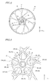
- FIG. 3 is a side view enlargedly showing the hub 20 of the wheel 10.
- FIG. 4 is a perspective view of the hub 20.
- FIG. 5 is a side view enlargedly showing the hub 20 which is viewed from the opposite side to FIG. 3 .
- the radial direction and circumferential direction of the wheel 10 are simply referred to as "radial direction” and “circumferential direction", respectively.
- the hub 20 includes, as shown in FIG. 2 to FIG. 5 , an inner perimeter portion 22 having a hole 16 through which an axle is to be inserted and an outer perimeter portion 24 to which the spokes 14 are connected.
- the center axis of the axle corresponds to a rotation axis line 18 of the wheel 10 (see FIG. 4 ).
- a direction in which the rotation axis line 18 of the wheel 10 extends is referred to as "rotation axis line direction”.
- the inner perimeter portion 22 and the outer perimeter portion 24 each have the shape of a cylinder extending in the rotation axis line direction.
- the inner perimeter portion 22 has the shape of a generally circular cylinder
- the outer perimeter portion 24 has the shape of a generally polygonal cylinder (more specifically, a generally pentagonal cylinder).
- the shape of the inner perimeter portion 22 and the shape of the outer perimeter portion 24 are not limited to those illustrated herein.
- the outer perimeter portion 24 may have the shape of a generally circular cylinder.
- the outer perimeter portion 24 has a plurality of holes 28 which are used for securing the brake disk 110 (see FIG. 1 ). For example, bolts are screwed into these holes 28.
- the hub 20 has a plurality of connecting portions 26 connecting the inner perimeter portion 22 and the outer perimeter portion 24.
- the plurality of connecting portions 26 are arranged so as to radially extend from the inner perimeter portion 22 to the outer perimeter portion 24 and to be spaced away from one another in the circumferential direction.
- the plurality of connecting portions 26 include, as shown in FIG. 4 , a plurality of first connecting portions 26L located on one side of the wheel 10 in the rotation axis line direction and a plurality of second connecting portions 26R located on the other side.
- the plurality of first connecting portions 26L are located on the left side
- the plurality of second connecting portions 26R are on the right side.
- each of the number of first connecting portions 26L and the number of second connecting portions 26R is five.
- each of the first connecting portions 26L is present between two of the second connecting portions 26R adjoining each other in the circumferential direction
- each of the second connecting portions 26R is present between two of the first connecting portions 26L adjoining each other in the circumferential direction. That is, the first connecting portions 26L and the second connecting portions 26R are at positions shifted from one another in the circumferential direction.
- the first connecting portions 26L and the second connecting portions 26R do not overlap one another. In other words, when the hub 20 is viewed from the rotation axis line direction, the first connecting portions 26L and the second connecting portions 26R are alternately arranged along the circumferential direction.
- the plurality of first connecting portions 26L are arranged with generally equal pitches in the circumferential direction.
- five first connecting portions 26L are arranged with the pitches of approximately 72°.
- the plurality of second connecting portions 26R are arranged with generally equal pitches in the circumferential direction.
- five second connecting portions 26R are arranged with the pitches of approximately 72°.
- each of the first connecting portions 26L is located generally equally distant from two of the second connecting portions 26R adjoining that first connecting portion 26L (i.e., located at a position which halves the pitch of the second connecting portions 26R ).
- each of the second connecting portions 26R is located generally equally distant from two of the first connecting portions 26L adjoining that second connecting portion 26R (i.e., located at a position which halves the pitch of the first connecting portions 26L ).
- the plurality of first connecting portions 26L and the plurality of second connecting portions 26R are located at positions shifted from one another by a half of the pitch in the circumferential direction of the hub 20.
- a through hole 32 penetrating in the rotation axis line direction is provided between a first connecting portion 26L and a second connecting portion 26R adjoining each other in the circumferential direction.
- the projected areas in the rotation axis line direction of these two through holes 32 are generally equal.
- Each of the first connecting portions 26L and the second connecting portions 26R of the present embodiment has a stick-like shape.
- the cross-sectional shape of each of the first connecting portions 26L and the second connecting portions 26R is arbitrary. For example, it can be polygonal, circular, or elliptical.
- the hub 20 may have ribs 27 near the inner perimeter portion 22 for partially connecting a first connecting portion 26L and a second connecting portion 26R adjoining each other.
- the ribs 27 extend in the rotation axis line direction across the outer perimeter surface of the inner perimeter portion 22. Note that, however, even when the ribs 27 are provided, the ribs 27 do not connect a first connecting portion 26L and a second connecting portion 26R adjoining each other over the entire radial dimension. That is, the first connecting portions 26L and the second connecting portions 26R include parts which are not connected to each other by the ribs 27.
- the plurality of connecting portions 26 of the hub 20 include a plurality of first connecting portions 26L located on one side in the rotation axis line direction and a plurality of second connecting portions 26R located on the other side.
- first connecting portions 26L located on one side in the rotation axis line direction
- second connecting portions 26R located on the other side.
- the wheel 10 of the present embodiment is manufactured by means of die casting such that these spaces and through holes 32 are formed, the mass of the wheel 10 can be reduced, and the amount of the metal material used for manufacture can be reduced. Therefore, weight reduction can be realized, and the manufacturing cost can be reduced.
- each of the first connecting portions 26L and the second connecting portions 26R has a stick-like shape as in the present embodiment, the projected areas in the rotation axis line direction of the through holes 32 can easily be increased. Therefore, weight reduction of the wheel 10 and reduction of the manufacturing cost can be realized more easily.
- first connecting portions 26L and the second connecting portions 26R that have a stick-like shape
- three different lengths are considered.
- length L3 defined along the radial direction of the first connecting portion 26L are considered (see FIG. 4 ).
- lengths L1, L2 and L3 are referred to as "first length”, “second length” and "third length”, respectively, for the sake of convenience.
- length L1' defined along the first direction that is the longitudinal direction, length L2' defined along the second direction that is perpendicular to the first direction, and length L3' defined along the radial direction of the second connecting portion 26R are considered (see FIG. 4 ).
- lengths L1', L2' and L3' are also referred to as "first length”, “second length” and “third length”, respectively, for the sake of convenience.
- the ratio between first length L1 and second length L2 of the first connecting portion 26L and the ratio between first length L1' and second length L2' of the second connecting portion 26R are each preferably within a predetermined range. Specifically, when the ratio between first length L1 and second length L2 of the first connecting portion 26L is from 1:1 to 1.5:1, the strength of the hub can be sufficiently secured, and the projected area of the through holes 32 in the rotation axis line direction can be sufficiently large. Likewise, when the ratio between first length L1' and second length L2' of the second connecting portion 26R is from 1:1 to 1.5:1, the strength of the hub can be sufficiently secured, and the projected area of the through holes 32 in the rotation axis line direction can be sufficiently large.
- the weight reduction can be further enhanced. Specifically, when the ratio of third length L3 to first length L1 exceeds 1, i.e., when third length L3 is greater than first length L1 (in other words, when the first connecting portion 26L has a shape elongated in the radial direction), sufficient weight reduction can be achieved.
- the weight reduction can be further enhanced. Specifically, when the ratio of third length L3' to first length L1' exceeds 1, i.e., when third length L3' is greater than first length L1' (in other words, when the second connecting portion 26R has a shape elongated in the radial direction), sufficient weight reduction can be achieved.
- a first connecting portion 26L is generally equally distant from two second connecting portions 26R
- a second connecting portion 26R is generally equally distant from two first connecting portions 26L . That is, the plurality of first connecting portions 26L and the plurality of second connecting portions 26R are located at positions shifted from one another by a half of the pitch in the circumferential direction of the hub 20. Using such a configuration makes manufacture and design easier.
- the hub 20 has five first connecting portions 26L and five second connecting portions 26R
- the number of the plurality of first connecting portions 26L and the number of the plurality of second connecting portions 26R are arbitrary and are not particularly limited. From the viewpoints of weight reduction and improvement in maintenance easiness, the number of the plurality of first connecting portions and the number of the plurality of second connecting portions are preferably smaller. Specifically, it is preferred that the number of the plurality of first connecting portions and the number of the plurality of second connecting portions are each not more than five. Note that, however, from the viewpoint of securing sufficiently high hub strength, it is preferred that the number of the plurality of first connecting portions and the number of the plurality of second connecting portions are each not less than three.
- the illustrated aluminum alloy or magnesium alloy as the material of the wheel 10 enables to reduce the weight of the wheel.
- the through holes 32 are provided between the first connecting portions 26L and the second connecting portions 26R as in the present embodiment, the weight of a wheel which is made of an aluminum alloy or a wheel which is made of a magnesium alloy can be further reduced, and the manufacturing cost can also be reduced.
- the holes 28 are provided in the outer perimeter portion 24 of the hub 20 for securing the brake disk 110.
- the through holes 32 are provided between the first connecting portions 26L and the second connecting portions 26R as in the present embodiment, the hub 20 can be easily cleaned even if the brake disk 110 is kept secured to the wheel 10 .
- the wheel 10 of the present embodiment is manufactured using die casting.
- the mold used in die casting only needs to be a mold whose cavity is defined so as to have a shape corresponding to the hub 20 that has the above-described configuration.
- FIG. 6 and FIG. 7 show a mold 40 for use in die casting that is for manufacture of the wheel 10.
- FIG. 6 and FIG. 7 respectively show a cross-sectional structure of the opened mold 40 and a cross-sectional structure of the closed mold 40, each showing a region that forms a portion of the hub 20 taken along line B-B of FIG. 3 .
- the mold 40 includes two die plates 41 and 42 as shown in FIG. 6 and FIG. 7 .
- the die plate 41 is the movable die plate
- the die plate 42 is the stationary die plate.
- the die plate 41 is the stationary die plate while the die plate 42 is the movable die plate.
- a cavity (space) 43 which has a shape corresponding to the wheel 10 is formed between the movable die plate 41 and the stationary die plate 42.
- This cavity 43 includes regions corresponding to the first connecting portions 26L of the hub 20 (first regions 43a ) and regions corresponding to the second connecting portions 26R of the hub 20 (second regions 43b ). As seen from FIG. 7 , there are no spaces between the first regions 43a and the second regions 43b.
- Molten metal of a raw material (e.g., aluminum alloy) is injected into the cavity 43 of the closed mold 40.
- the injection pressure is, for example, not less than 20 MPa, and the injection rate is, for example, not less than 5 m/s.
- the material is cooled, whereby first connecting portions 26L are formed in the first regions 43a and second connecting portions 26R are formed in the second regions 43b as shown in FIG. 8 .
- the mold 40 is opened again for separating a molded product from the mold, whereby a wheel 10 is obtained. Since as previously described there are no spaces between the first regions 43a and the second regions 43b when the mold 40 is closed (see FIG.
- the completed wheel 10 has the through holes 32 between the first connecting portions 26L corresponding to the first regions 43a and the second connecting portions 26R corresponding to the second regions 43b . Therefore, the mass of the wheel 10 can be reduced, and the amount of the metal material used for manufacture can be reduced. Thus, weight reduction can be realized, and the manufacturing cost can be reduced.
- FIG. 9 and FIG. 10 show other examples of the arrangement of the first connecting portions 26L and the second connecting portions 26R .
- the first connecting portions 26L of the example illustrated in FIG. 9 are located at positions shifted clockwise relative to the first connecting portions 26L of the example illustrated in FIG. 3 .
- the first connecting portions 26L are located at positions shifted clockwise by 3/4 of the pitch relative to the second connecting portions 26R .
- the projected areas in the rotation axis line direction of these two through holes 32 are different from each other.
- the projected areas in the rotation axis line direction of these two through holes 32 are different from each other.
- the first connecting portions 26L of the example illustrated in FIG. 10 are located at positions shifted anticlockwise relative to the first connecting portions 26L of the example illustrated in FIG. 3 .
- the first connecting portions 26L are located at positions shifted clockwise by 1/4 of the pitch relative to the second connecting portions 26R.
- a wheel for straddled vehicles which is manufactured using die casting (i.e., which is a die-cast product)
- weight reduction can be realized, and the manufacturing cost can be reduced.
- cleaning of the hub is easy, so that maintenance easiness can be improved.
- a wheel for straddled vehicles according to an embodiment of the present invention is suitably used in various straddled vehicles, typically two-wheeled motorcycles.
Landscapes
- Engineering & Computer Science (AREA)
- Mechanical Engineering (AREA)
- General Engineering & Computer Science (AREA)
- Transportation (AREA)
- Chemical & Material Sciences (AREA)
- Combustion & Propulsion (AREA)
- Molds, Cores, And Manufacturing Methods Thereof (AREA)
Applications Claiming Priority (2)
| Application Number | Priority Date | Filing Date | Title |
|---|---|---|---|
| JP2015143104 | 2015-07-17 | ||
| JP2016104834A JP2017024705A (ja) | 2015-07-17 | 2016-05-26 | 鞍乗型車両用ホイールおよび鞍乗型車両 |
Publications (3)
| Publication Number | Publication Date |
|---|---|
| EP3135573A2 true EP3135573A2 (fr) | 2017-03-01 |
| EP3135573A3 EP3135573A3 (fr) | 2017-03-29 |
| EP3135573B1 EP3135573B1 (fr) | 2018-07-04 |
Family
ID=56550026
Family Applications (1)
| Application Number | Title | Priority Date | Filing Date |
|---|---|---|---|
| EP16178907.8A Active EP3135573B1 (fr) | 2015-07-17 | 2016-07-11 | Roue pour véhicules à califourchon et véhicule à califourchon |
Country Status (1)
| Country | Link |
|---|---|
| EP (1) | EP3135573B1 (fr) |
Cited By (1)
| Publication number | Priority date | Publication date | Assignee | Title |
|---|---|---|---|---|
| EP3725540A1 (fr) * | 2019-04-19 | 2020-10-21 | Yamaha Hatsudoki Kabushiki Kaisha | Roue coulée sous pression, unité de roue et véhicule à enfourcher |
Citations (1)
| Publication number | Priority date | Publication date | Assignee | Title |
|---|---|---|---|---|
| JPH06183201A (ja) | 1992-12-18 | 1994-07-05 | Yamaha Motor Co Ltd | 自動二輪車用ダイカスト製ホイール |
Family Cites Families (5)
| Publication number | Priority date | Publication date | Assignee | Title |
|---|---|---|---|---|
| JPS5812801A (ja) * | 1981-07-17 | 1983-01-25 | Yamaha Motor Co Ltd | 自動二輪車用ホイ−ル |
| DE4013603A1 (de) * | 1989-05-03 | 1991-02-07 | Ulrich Dipl Ing Wahl | Motorradgussrad |
| DE19601778C2 (de) * | 1995-10-11 | 1998-09-10 | Porsche Ag | Rad für ein Kraftfahrzeug |
| JPH1029402A (ja) * | 1996-07-16 | 1998-02-03 | Honda Motor Co Ltd | 車両用ホイール |
| JP3836392B2 (ja) * | 2002-04-26 | 2006-10-25 | 本田技研工業株式会社 | 自動二輪車用ホイール |
-
2016
- 2016-07-11 EP EP16178907.8A patent/EP3135573B1/fr active Active
Patent Citations (1)
| Publication number | Priority date | Publication date | Assignee | Title |
|---|---|---|---|---|
| JPH06183201A (ja) | 1992-12-18 | 1994-07-05 | Yamaha Motor Co Ltd | 自動二輪車用ダイカスト製ホイール |
Cited By (1)
| Publication number | Priority date | Publication date | Assignee | Title |
|---|---|---|---|---|
| EP3725540A1 (fr) * | 2019-04-19 | 2020-10-21 | Yamaha Hatsudoki Kabushiki Kaisha | Roue coulée sous pression, unité de roue et véhicule à enfourcher |
Also Published As
| Publication number | Publication date |
|---|---|
| EP3135573A3 (fr) | 2017-03-29 |
| EP3135573B1 (fr) | 2018-07-04 |
Similar Documents
| Publication | Publication Date | Title |
|---|---|---|
| CN106687302A (zh) | 铸铝车轮 | |
| US20100239363A1 (en) | Connecting flange for transmission elements of cycles and motorcycles | |
| JP2010501399A (ja) | 二輪車 | |
| US9511622B2 (en) | Wheel of vehicle | |
| EP3135573B1 (fr) | Roue pour véhicules à califourchon et véhicule à califourchon | |
| JP6043029B2 (ja) | 自動二輪車用のアルミホイール | |
| EP2626217B1 (fr) | Roue pour motocyclette | |
| JP2017024705A (ja) | 鞍乗型車両用ホイールおよび鞍乗型車両 | |
| EP3222439B1 (fr) | Roue coulée et véhicule de type à selle | |
| US8550201B2 (en) | Swing arm for miniaturized vehicle | |
| JPWO2019097908A1 (ja) | ストラドルドビークル用変動荷重伝達部品、ストラドルドビークル及びクラッチハブの射出成形方法 | |
| JP6572708B2 (ja) | スイングアーム | |
| JP6043336B2 (ja) | ホイール及び自動二輪車 | |
| JP6352590B2 (ja) | 鞍乗り型車両のホイール及びその周辺構造 | |
| CN110015372B (zh) | 框架结构 | |
| JP2003320801A (ja) | 自動二輪車用ホイール | |
| JP6411879B2 (ja) | 鞍乗型車両 | |
| CN203921107U (zh) | 车轮组件、电机轮组件及踏板车 | |
| JP7386078B2 (ja) | 人力駆動車用のドライブユニットおよび人力駆動車用のドライブユニットの製造方法 | |
| JP6850823B2 (ja) | キャストホイール | |
| JP2018069985A (ja) | 非空気入りタイヤおよび二輪車 | |
| CN105346669B (zh) | 无链自行车及其轮组 | |
| TWI676571B (zh) | 跨坐型車輛及其組裝方法 | |
| WO2015182247A1 (fr) | Structure pour roue de véhicule à selle | |
| EP3533621A1 (fr) | Structure d'amortisseur de roue |
Legal Events
| Date | Code | Title | Description |
|---|---|---|---|
| PUAI | Public reference made under article 153(3) epc to a published international application that has entered the european phase |
Free format text: ORIGINAL CODE: 0009012 |
|
| STAA | Information on the status of an ep patent application or granted ep patent |
Free format text: STATUS: THE APPLICATION HAS BEEN PUBLISHED |
|
| PUAL | Search report despatched |
Free format text: ORIGINAL CODE: 0009013 |
|
| AK | Designated contracting states |
Kind code of ref document: A2 Designated state(s): AL AT BE BG CH CY CZ DE DK EE ES FI FR GB GR HR HU IE IS IT LI LT LU LV MC MK MT NL NO PL PT RO RS SE SI SK SM TR |
|
| AX | Request for extension of the european patent |
Extension state: BA ME |
|
| AK | Designated contracting states |
Kind code of ref document: A3 Designated state(s): AL AT BE BG CH CY CZ DE DK EE ES FI FR GB GR HR HU IE IS IT LI LT LU LV MC MK MT NL NO PL PT RO RS SE SI SK SM TR |
|
| AX | Request for extension of the european patent |
Extension state: BA ME |
|
| RIC1 | Information provided on ipc code assigned before grant |
Ipc: B60B 1/08 20060101ALI20170220BHEP Ipc: B62K 11/04 20060101AFI20170220BHEP Ipc: B62M 7/04 20060101ALI20170220BHEP Ipc: B60T 1/06 20060101ALI20170220BHEP |
|
| STAA | Information on the status of an ep patent application or granted ep patent |
Free format text: STATUS: REQUEST FOR EXAMINATION WAS MADE |
|
| 17P | Request for examination filed |
Effective date: 20170904 |
|
| RBV | Designated contracting states (corrected) |
Designated state(s): AL AT BE BG CH CY CZ DE DK EE ES FI FR GB GR HR HU IE IS IT LI LT LU LV MC MK MT NL NO PL PT RO RS SE SI SK SM TR |
|
| GRAP | Despatch of communication of intention to grant a patent |
Free format text: ORIGINAL CODE: EPIDOSNIGR1 |
|
| STAA | Information on the status of an ep patent application or granted ep patent |
Free format text: STATUS: GRANT OF PATENT IS INTENDED |
|
| INTG | Intention to grant announced |
Effective date: 20180115 |
|
| GRAS | Grant fee paid |
Free format text: ORIGINAL CODE: EPIDOSNIGR3 |
|
| GRAA | (expected) grant |
Free format text: ORIGINAL CODE: 0009210 |
|
| STAA | Information on the status of an ep patent application or granted ep patent |
Free format text: STATUS: THE PATENT HAS BEEN GRANTED |
|
| AK | Designated contracting states |
Kind code of ref document: B1 Designated state(s): AL AT BE BG CH CY CZ DE DK EE ES FI FR GB GR HR HU IE IS IT LI LT LU LV MC MK MT NL NO PL PT RO RS SE SI SK SM TR |
|
| REG | Reference to a national code |
Ref country code: GB Ref legal event code: FG4D |
|
| REG | Reference to a national code |
Ref country code: CH Ref legal event code: EP |
|
| REG | Reference to a national code |
Ref country code: AT Ref legal event code: REF Ref document number: 1014191 Country of ref document: AT Kind code of ref document: T Effective date: 20180715 |
|
| REG | Reference to a national code |
Ref country code: IE Ref legal event code: FG4D |
|
| REG | Reference to a national code |
Ref country code: FR Ref legal event code: PLFP Year of fee payment: 3 |
|
| REG | Reference to a national code |
Ref country code: DE Ref legal event code: R096 Ref document number: 602016003931 Country of ref document: DE |
|
| REG | Reference to a national code |
Ref country code: NL Ref legal event code: MP Effective date: 20180704 |
|
| REG | Reference to a national code |
Ref country code: LT Ref legal event code: MG4D |
|
| REG | Reference to a national code |
Ref country code: AT Ref legal event code: MK05 Ref document number: 1014191 Country of ref document: AT Kind code of ref document: T Effective date: 20180704 |
|
| PG25 | Lapsed in a contracting state [announced via postgrant information from national office to epo] |
Ref country code: NL Free format text: LAPSE BECAUSE OF FAILURE TO SUBMIT A TRANSLATION OF THE DESCRIPTION OR TO PAY THE FEE WITHIN THE PRESCRIBED TIME-LIMIT Effective date: 20180704 |
|
| PG25 | Lapsed in a contracting state [announced via postgrant information from national office to epo] |
Ref country code: CZ Free format text: LAPSE BECAUSE OF FAILURE TO SUBMIT A TRANSLATION OF THE DESCRIPTION OR TO PAY THE FEE WITHIN THE PRESCRIBED TIME-LIMIT Effective date: 20180704 Ref country code: BG Free format text: LAPSE BECAUSE OF FAILURE TO SUBMIT A TRANSLATION OF THE DESCRIPTION OR TO PAY THE FEE WITHIN THE PRESCRIBED TIME-LIMIT Effective date: 20181004 Ref country code: PL Free format text: LAPSE BECAUSE OF FAILURE TO SUBMIT A TRANSLATION OF THE DESCRIPTION OR TO PAY THE FEE WITHIN THE PRESCRIBED TIME-LIMIT Effective date: 20180704 Ref country code: LT Free format text: LAPSE BECAUSE OF FAILURE TO SUBMIT A TRANSLATION OF THE DESCRIPTION OR TO PAY THE FEE WITHIN THE PRESCRIBED TIME-LIMIT Effective date: 20180704 Ref country code: SE Free format text: LAPSE BECAUSE OF FAILURE TO SUBMIT A TRANSLATION OF THE DESCRIPTION OR TO PAY THE FEE WITHIN THE PRESCRIBED TIME-LIMIT Effective date: 20180704 Ref country code: AT Free format text: LAPSE BECAUSE OF FAILURE TO SUBMIT A TRANSLATION OF THE DESCRIPTION OR TO PAY THE FEE WITHIN THE PRESCRIBED TIME-LIMIT Effective date: 20180704 Ref country code: FI Free format text: LAPSE BECAUSE OF FAILURE TO SUBMIT A TRANSLATION OF THE DESCRIPTION OR TO PAY THE FEE WITHIN THE PRESCRIBED TIME-LIMIT Effective date: 20180704 Ref country code: RS Free format text: LAPSE BECAUSE OF FAILURE TO SUBMIT A TRANSLATION OF THE DESCRIPTION OR TO PAY THE FEE WITHIN THE PRESCRIBED TIME-LIMIT Effective date: 20180704 Ref country code: IS Free format text: LAPSE BECAUSE OF FAILURE TO SUBMIT A TRANSLATION OF THE DESCRIPTION OR TO PAY THE FEE WITHIN THE PRESCRIBED TIME-LIMIT Effective date: 20181104 Ref country code: GR Free format text: LAPSE BECAUSE OF FAILURE TO SUBMIT A TRANSLATION OF THE DESCRIPTION OR TO PAY THE FEE WITHIN THE PRESCRIBED TIME-LIMIT Effective date: 20181005 Ref country code: NO Free format text: LAPSE BECAUSE OF FAILURE TO SUBMIT A TRANSLATION OF THE DESCRIPTION OR TO PAY THE FEE WITHIN THE PRESCRIBED TIME-LIMIT Effective date: 20181004 |
|
| PG25 | Lapsed in a contracting state [announced via postgrant information from national office to epo] |
Ref country code: ES Free format text: LAPSE BECAUSE OF FAILURE TO SUBMIT A TRANSLATION OF THE DESCRIPTION OR TO PAY THE FEE WITHIN THE PRESCRIBED TIME-LIMIT Effective date: 20180704 Ref country code: HR Free format text: LAPSE BECAUSE OF FAILURE TO SUBMIT A TRANSLATION OF THE DESCRIPTION OR TO PAY THE FEE WITHIN THE PRESCRIBED TIME-LIMIT Effective date: 20180704 Ref country code: LV Free format text: LAPSE BECAUSE OF FAILURE TO SUBMIT A TRANSLATION OF THE DESCRIPTION OR TO PAY THE FEE WITHIN THE PRESCRIBED TIME-LIMIT Effective date: 20180704 Ref country code: AL Free format text: LAPSE BECAUSE OF FAILURE TO SUBMIT A TRANSLATION OF THE DESCRIPTION OR TO PAY THE FEE WITHIN THE PRESCRIBED TIME-LIMIT Effective date: 20180704 |
|
| PG25 | Lapsed in a contracting state [announced via postgrant information from national office to epo] |
Ref country code: LU Free format text: LAPSE BECAUSE OF NON-PAYMENT OF DUE FEES Effective date: 20180711 |
|
| REG | Reference to a national code |
Ref country code: BE Ref legal event code: MM Effective date: 20180731 |
|
| REG | Reference to a national code |
Ref country code: DE Ref legal event code: R097 Ref document number: 602016003931 Country of ref document: DE |
|
| REG | Reference to a national code |
Ref country code: IE Ref legal event code: MM4A |
|
| PG25 | Lapsed in a contracting state [announced via postgrant information from national office to epo] |
Ref country code: EE Free format text: LAPSE BECAUSE OF FAILURE TO SUBMIT A TRANSLATION OF THE DESCRIPTION OR TO PAY THE FEE WITHIN THE PRESCRIBED TIME-LIMIT Effective date: 20180704 Ref country code: RO Free format text: LAPSE BECAUSE OF FAILURE TO SUBMIT A TRANSLATION OF THE DESCRIPTION OR TO PAY THE FEE WITHIN THE PRESCRIBED TIME-LIMIT Effective date: 20180704 Ref country code: MC Free format text: LAPSE BECAUSE OF FAILURE TO SUBMIT A TRANSLATION OF THE DESCRIPTION OR TO PAY THE FEE WITHIN THE PRESCRIBED TIME-LIMIT Effective date: 20180704 Ref country code: IE Free format text: LAPSE BECAUSE OF NON-PAYMENT OF DUE FEES Effective date: 20180711 |
|
| PLBE | No opposition filed within time limit |
Free format text: ORIGINAL CODE: 0009261 |
|
| STAA | Information on the status of an ep patent application or granted ep patent |
Free format text: STATUS: NO OPPOSITION FILED WITHIN TIME LIMIT |
|
| PG25 | Lapsed in a contracting state [announced via postgrant information from national office to epo] |
Ref country code: SK Free format text: LAPSE BECAUSE OF FAILURE TO SUBMIT A TRANSLATION OF THE DESCRIPTION OR TO PAY THE FEE WITHIN THE PRESCRIBED TIME-LIMIT Effective date: 20180704 Ref country code: BE Free format text: LAPSE BECAUSE OF NON-PAYMENT OF DUE FEES Effective date: 20180731 Ref country code: DK Free format text: LAPSE BECAUSE OF FAILURE TO SUBMIT A TRANSLATION OF THE DESCRIPTION OR TO PAY THE FEE WITHIN THE PRESCRIBED TIME-LIMIT Effective date: 20180704 Ref country code: SM Free format text: LAPSE BECAUSE OF FAILURE TO SUBMIT A TRANSLATION OF THE DESCRIPTION OR TO PAY THE FEE WITHIN THE PRESCRIBED TIME-LIMIT Effective date: 20180704 |
|
| 26N | No opposition filed |
Effective date: 20190405 |
|
| PG25 | Lapsed in a contracting state [announced via postgrant information from national office to epo] |
Ref country code: SI Free format text: LAPSE BECAUSE OF FAILURE TO SUBMIT A TRANSLATION OF THE DESCRIPTION OR TO PAY THE FEE WITHIN THE PRESCRIBED TIME-LIMIT Effective date: 20180704 |
|
| PG25 | Lapsed in a contracting state [announced via postgrant information from national office to epo] |
Ref country code: MT Free format text: LAPSE BECAUSE OF NON-PAYMENT OF DUE FEES Effective date: 20180711 |
|
| REG | Reference to a national code |
Ref country code: CH Ref legal event code: PL |
|
| PG25 | Lapsed in a contracting state [announced via postgrant information from national office to epo] |
Ref country code: TR Free format text: LAPSE BECAUSE OF FAILURE TO SUBMIT A TRANSLATION OF THE DESCRIPTION OR TO PAY THE FEE WITHIN THE PRESCRIBED TIME-LIMIT Effective date: 20180704 |
|
| PG25 | Lapsed in a contracting state [announced via postgrant information from national office to epo] |
Ref country code: LI Free format text: LAPSE BECAUSE OF NON-PAYMENT OF DUE FEES Effective date: 20190731 Ref country code: CH Free format text: LAPSE BECAUSE OF NON-PAYMENT OF DUE FEES Effective date: 20190731 Ref country code: PT Free format text: LAPSE BECAUSE OF FAILURE TO SUBMIT A TRANSLATION OF THE DESCRIPTION OR TO PAY THE FEE WITHIN THE PRESCRIBED TIME-LIMIT Effective date: 20180704 |
|
| PG25 | Lapsed in a contracting state [announced via postgrant information from national office to epo] |
Ref country code: MK Free format text: LAPSE BECAUSE OF NON-PAYMENT OF DUE FEES Effective date: 20180704 Ref country code: HU Free format text: LAPSE BECAUSE OF FAILURE TO SUBMIT A TRANSLATION OF THE DESCRIPTION OR TO PAY THE FEE WITHIN THE PRESCRIBED TIME-LIMIT; INVALID AB INITIO Effective date: 20160711 Ref country code: CY Free format text: LAPSE BECAUSE OF FAILURE TO SUBMIT A TRANSLATION OF THE DESCRIPTION OR TO PAY THE FEE WITHIN THE PRESCRIBED TIME-LIMIT Effective date: 20180704 |
|
| GBPC | Gb: european patent ceased through non-payment of renewal fee |
Effective date: 20200711 |
|
| PG25 | Lapsed in a contracting state [announced via postgrant information from national office to epo] |
Ref country code: GB Free format text: LAPSE BECAUSE OF NON-PAYMENT OF DUE FEES Effective date: 20200711 |
|
| P01 | Opt-out of the competence of the unified patent court (upc) registered |
Effective date: 20230527 |
|
| PGFP | Annual fee paid to national office [announced via postgrant information from national office to epo] |
Ref country code: IT Payment date: 20230724 Year of fee payment: 8 |
|
| PGFP | Annual fee paid to national office [announced via postgrant information from national office to epo] |
Ref country code: FR Payment date: 20230726 Year of fee payment: 8 Ref country code: DE Payment date: 20230719 Year of fee payment: 8 |