EP3132945B1 - Verfahren zur herstellung eines dekorierten wand- oder bodenpaneels - Google Patents
Verfahren zur herstellung eines dekorierten wand- oder bodenpaneels Download PDFInfo
- Publication number
- EP3132945B1 EP3132945B1 EP15181523.0A EP15181523A EP3132945B1 EP 3132945 B1 EP3132945 B1 EP 3132945B1 EP 15181523 A EP15181523 A EP 15181523A EP 3132945 B1 EP3132945 B1 EP 3132945B1
- Authority
- EP
- European Patent Office
- Prior art keywords
- carrier
- temperature
- belt
- wood
- double
- Prior art date
- Legal status (The legal status is an assumption and is not a legal conclusion. Google has not performed a legal analysis and makes no representation as to the accuracy of the status listed.)
- Active
Links
- 238000004519 manufacturing process Methods 0.000 title claims description 23
- 238000000034 method Methods 0.000 claims description 143
- 239000000463 material Substances 0.000 claims description 87
- 239000012876 carrier material Substances 0.000 claims description 80
- 238000007906 compression Methods 0.000 claims description 44
- 230000006835 compression Effects 0.000 claims description 43
- 239000002023 wood Substances 0.000 claims description 43
- 238000003825 pressing Methods 0.000 claims description 41
- 238000001816 cooling Methods 0.000 claims description 37
- -1 polyethylene Polymers 0.000 claims description 33
- 229920003023 plastic Polymers 0.000 claims description 29
- 239000004033 plastic Substances 0.000 claims description 29
- FGUUSXIOTUKUDN-IBGZPJMESA-N C1(=CC=CC=C1)N1C2=C(NC([C@H](C1)NC=1OC(=NN=1)C1=CC=CC=C1)=O)C=CC=C2 Chemical compound C1(=CC=CC=C1)N1C2=C(NC([C@H](C1)NC=1OC(=NN=1)C1=CC=CC=C1)=O)C=CC=C2 FGUUSXIOTUKUDN-IBGZPJMESA-N 0.000 claims description 22
- 230000009471 action Effects 0.000 claims description 22
- 239000004743 Polypropylene Substances 0.000 claims description 21
- 229920001155 polypropylene Polymers 0.000 claims description 21
- 239000004698 Polyethylene Substances 0.000 claims description 18
- 229920000573 polyethylene Polymers 0.000 claims description 18
- 239000008187 granular material Substances 0.000 claims description 17
- 238000005496 tempering Methods 0.000 claims description 16
- 238000005034 decoration Methods 0.000 claims description 15
- 239000011155 wood-plastic composite Substances 0.000 claims description 14
- 238000000465 moulding Methods 0.000 claims description 13
- 229920001343 polytetrafluoroethylene Polymers 0.000 claims description 11
- 238000002425 crystallisation Methods 0.000 claims description 10
- 230000008025 crystallization Effects 0.000 claims description 10
- 238000002844 melting Methods 0.000 claims description 10
- 230000008018 melting Effects 0.000 claims description 10
- 239000004810 polytetrafluoroethylene Substances 0.000 claims description 9
- 239000003795 chemical substances by application Substances 0.000 claims description 8
- 239000011241 protective layer Substances 0.000 claims description 8
- 229910000831 Steel Inorganic materials 0.000 claims description 7
- 239000010959 steel Substances 0.000 claims description 7
- 230000036961 partial effect Effects 0.000 claims description 6
- 229920001587 Wood-plastic composite Polymers 0.000 claims description 4
- 229920001577 copolymer Polymers 0.000 claims description 4
- 239000002245 particle Substances 0.000 description 45
- 239000010410 layer Substances 0.000 description 39
- 239000000203 mixture Substances 0.000 description 27
- 238000009826 distribution Methods 0.000 description 24
- 239000002657 fibrous material Substances 0.000 description 19
- 238000010438 heat treatment Methods 0.000 description 15
- 239000004800 polyvinyl chloride Substances 0.000 description 15
- 229920000915 polyvinyl chloride Polymers 0.000 description 14
- 230000008569 process Effects 0.000 description 14
- 239000000123 paper Substances 0.000 description 12
- 229920000642 polymer Polymers 0.000 description 11
- 239000000758 substrate Substances 0.000 description 10
- 238000007639 printing Methods 0.000 description 9
- 239000000047 product Substances 0.000 description 9
- 239000000654 additive Substances 0.000 description 7
- 239000012963 UV stabilizer Substances 0.000 description 6
- 230000008901 benefit Effects 0.000 description 6
- 239000000969 carrier Substances 0.000 description 6
- 239000000470 constituent Substances 0.000 description 6
- 229920005989 resin Polymers 0.000 description 6
- 239000011347 resin Substances 0.000 description 6
- 239000007787 solid Substances 0.000 description 6
- 239000000454 talc Substances 0.000 description 6
- 229910052623 talc Inorganic materials 0.000 description 6
- 235000012222 talc Nutrition 0.000 description 6
- 238000000576 coating method Methods 0.000 description 5
- 239000011162 core material Substances 0.000 description 5
- 239000012760 heat stabilizer Substances 0.000 description 5
- 239000003921 oil Substances 0.000 description 5
- 239000008188 pellet Substances 0.000 description 5
- 230000002829 reductive effect Effects 0.000 description 5
- 238000007493 shaping process Methods 0.000 description 5
- XLYOFNOQVPJJNP-UHFFFAOYSA-N water Substances O XLYOFNOQVPJJNP-UHFFFAOYSA-N 0.000 description 5
- 229920001400 block copolymer Polymers 0.000 description 4
- 239000011093 chipboard Substances 0.000 description 4
- 239000011248 coating agent Substances 0.000 description 4
- 238000010017 direct printing Methods 0.000 description 4
- 230000000694 effects Effects 0.000 description 4
- 238000009499 grossing Methods 0.000 description 4
- 229910052751 metal Inorganic materials 0.000 description 4
- 239000002184 metal Substances 0.000 description 4
- 239000005445 natural material Substances 0.000 description 4
- 239000000126 substance Substances 0.000 description 4
- 229920001169 thermoplastic Polymers 0.000 description 4
- WSFSSNUMVMOOMR-UHFFFAOYSA-N Formaldehyde Chemical compound O=C WSFSSNUMVMOOMR-UHFFFAOYSA-N 0.000 description 3
- 230000007423 decrease Effects 0.000 description 3
- 239000011094 fiberboard Substances 0.000 description 3
- 235000013312 flour Nutrition 0.000 description 3
- 229920001519 homopolymer Polymers 0.000 description 3
- 239000000543 intermediate Substances 0.000 description 3
- 230000000670 limiting effect Effects 0.000 description 3
- 239000004014 plasticizer Substances 0.000 description 3
- 239000011120 plywood Substances 0.000 description 3
- 229920002959 polymer blend Polymers 0.000 description 3
- 239000011148 porous material Substances 0.000 description 3
- 238000003892 spreading Methods 0.000 description 3
- 230000007480 spreading Effects 0.000 description 3
- RNFJDJUURJAICM-UHFFFAOYSA-N 2,2,4,4,6,6-hexaphenoxy-1,3,5-triaza-2$l^{5},4$l^{5},6$l^{5}-triphosphacyclohexa-1,3,5-triene Chemical compound N=1P(OC=2C=CC=CC=2)(OC=2C=CC=CC=2)=NP(OC=2C=CC=CC=2)(OC=2C=CC=CC=2)=NP=1(OC=1C=CC=CC=1)OC1=CC=CC=C1 RNFJDJUURJAICM-UHFFFAOYSA-N 0.000 description 2
- 235000017166 Bambusa arundinacea Nutrition 0.000 description 2
- 235000017491 Bambusa tulda Nutrition 0.000 description 2
- VTYYLEPIZMXCLO-UHFFFAOYSA-L Calcium carbonate Chemical compound [Ca+2].[O-]C([O-])=O VTYYLEPIZMXCLO-UHFFFAOYSA-L 0.000 description 2
- 229920000877 Melamine resin Polymers 0.000 description 2
- 241001465754 Metazoa Species 0.000 description 2
- 244000082204 Phyllostachys viridis Species 0.000 description 2
- 235000015334 Phyllostachys viridis Nutrition 0.000 description 2
- 239000004696 Poly ether ether ketone Substances 0.000 description 2
- 239000004952 Polyamide Substances 0.000 description 2
- VYPSYNLAJGMNEJ-UHFFFAOYSA-N Silicium dioxide Chemical compound O=[Si]=O VYPSYNLAJGMNEJ-UHFFFAOYSA-N 0.000 description 2
- 229920002522 Wood fibre Polymers 0.000 description 2
- 239000011425 bamboo Substances 0.000 description 2
- 230000009286 beneficial effect Effects 0.000 description 2
- 235000013339 cereals Nutrition 0.000 description 2
- 150000001875 compounds Chemical class 0.000 description 2
- 238000001723 curing Methods 0.000 description 2
- 238000006073 displacement reaction Methods 0.000 description 2
- 238000004049 embossing Methods 0.000 description 2
- UHESRSKEBRADOO-UHFFFAOYSA-N ethyl carbamate;prop-2-enoic acid Chemical compound OC(=O)C=C.CCOC(N)=O UHESRSKEBRADOO-UHFFFAOYSA-N 0.000 description 2
- 239000000835 fiber Substances 0.000 description 2
- 239000000945 filler Substances 0.000 description 2
- 239000003063 flame retardant Substances 0.000 description 2
- 239000006260 foam Substances 0.000 description 2
- 229910052500 inorganic mineral Inorganic materials 0.000 description 2
- 238000009413 insulation Methods 0.000 description 2
- 238000007648 laser printing Methods 0.000 description 2
- 229920000092 linear low density polyethylene Polymers 0.000 description 2
- 239000004707 linear low-density polyethylene Substances 0.000 description 2
- 239000011707 mineral Substances 0.000 description 2
- 239000012764 mineral filler Substances 0.000 description 2
- 238000007645 offset printing Methods 0.000 description 2
- TWNQGVIAIRXVLR-UHFFFAOYSA-N oxo(oxoalumanyloxy)alumane Chemical compound O=[Al]O[Al]=O TWNQGVIAIRXVLR-UHFFFAOYSA-N 0.000 description 2
- 238000005554 pickling Methods 0.000 description 2
- 229920003229 poly(methyl methacrylate) Polymers 0.000 description 2
- 229920002647 polyamide Polymers 0.000 description 2
- 229920002530 polyetherether ketone Polymers 0.000 description 2
- 239000005020 polyethylene terephthalate Substances 0.000 description 2
- 229920000139 polyethylene terephthalate Polymers 0.000 description 2
- 239000002861 polymer material Substances 0.000 description 2
- 239000004926 polymethyl methacrylate Substances 0.000 description 2
- 239000004814 polyurethane Substances 0.000 description 2
- 239000011342 resin composition Substances 0.000 description 2
- 238000007650 screen-printing Methods 0.000 description 2
- 238000003860 storage Methods 0.000 description 2
- 239000010902 straw Substances 0.000 description 2
- 230000008961 swelling Effects 0.000 description 2
- 239000004416 thermosoftening plastic Substances 0.000 description 2
- 235000013311 vegetables Nutrition 0.000 description 2
- 239000001993 wax Substances 0.000 description 2
- 239000002025 wood fiber Substances 0.000 description 2
- 239000001763 2-hydroxyethyl(trimethyl)azanium Substances 0.000 description 1
- GNFTZDOKVXKIBK-UHFFFAOYSA-N 3-(2-methoxyethoxy)benzohydrazide Chemical compound COCCOC1=CC=CC(C(=O)NN)=C1 GNFTZDOKVXKIBK-UHFFFAOYSA-N 0.000 description 1
- 241000208140 Acer Species 0.000 description 1
- 239000004923 Acrylic lacquer Substances 0.000 description 1
- 229910052580 B4C Inorganic materials 0.000 description 1
- 235000018185 Betula X alpestris Nutrition 0.000 description 1
- 235000018212 Betula X uliginosa Nutrition 0.000 description 1
- 239000002028 Biomass Substances 0.000 description 1
- 241000167854 Bourreria succulenta Species 0.000 description 1
- 241001070941 Castanea Species 0.000 description 1
- 235000014036 Castanea Nutrition 0.000 description 1
- 229920003043 Cellulose fiber Polymers 0.000 description 1
- 244000060020 Chamaerops excelsa Species 0.000 description 1
- 235000013164 Chamaerops excelsa Nutrition 0.000 description 1
- 235000019743 Choline chloride Nutrition 0.000 description 1
- 229920000742 Cotton Polymers 0.000 description 1
- 241000195493 Cryptophyta Species 0.000 description 1
- 239000004641 Diallyl-phthalate Substances 0.000 description 1
- 240000003133 Elaeis guineensis Species 0.000 description 1
- 235000001950 Elaeis guineensis Nutrition 0.000 description 1
- JOYRKODLDBILNP-UHFFFAOYSA-N Ethyl urethane Chemical compound CCOC(N)=O JOYRKODLDBILNP-UHFFFAOYSA-N 0.000 description 1
- GYHNNYVSQQEPJS-UHFFFAOYSA-N Gallium Chemical compound [Ga] GYHNNYVSQQEPJS-UHFFFAOYSA-N 0.000 description 1
- 241000013479 Guibourtia coleosperma Species 0.000 description 1
- 240000007049 Juglans regia Species 0.000 description 1
- 235000009496 Juglans regia Nutrition 0.000 description 1
- 102000011782 Keratins Human genes 0.000 description 1
- 108010076876 Keratins Proteins 0.000 description 1
- 239000004640 Melamine resin Substances 0.000 description 1
- 239000004793 Polystyrene Substances 0.000 description 1
- 235000016976 Quercus macrolepis Nutrition 0.000 description 1
- 229910052581 Si3N4 Inorganic materials 0.000 description 1
- 244000186561 Swietenia macrophylla Species 0.000 description 1
- 239000004809 Teflon Substances 0.000 description 1
- 229920006362 Teflon® Polymers 0.000 description 1
- NRTOMJZYCJJWKI-UHFFFAOYSA-N Titanium nitride Chemical compound [Ti]#N NRTOMJZYCJJWKI-UHFFFAOYSA-N 0.000 description 1
- 229920001807 Urea-formaldehyde Polymers 0.000 description 1
- 244000208876 Washingtonia filifera Species 0.000 description 1
- 235000006574 Washingtonia filifera Nutrition 0.000 description 1
- 240000008042 Zea mays Species 0.000 description 1
- 235000005824 Zea mays ssp. parviglumis Nutrition 0.000 description 1
- 235000002017 Zea mays subsp mays Nutrition 0.000 description 1
- YTAHJIFKAKIKAV-XNMGPUDCSA-N [(1R)-3-morpholin-4-yl-1-phenylpropyl] N-[(3S)-2-oxo-5-phenyl-1,3-dihydro-1,4-benzodiazepin-3-yl]carbamate Chemical compound O=C1[C@H](N=C(C2=C(N1)C=CC=C2)C1=CC=CC=C1)NC(O[C@H](CCN1CCOCC1)C1=CC=CC=C1)=O YTAHJIFKAKIKAV-XNMGPUDCSA-N 0.000 description 1
- 238000005299 abrasion Methods 0.000 description 1
- 230000004308 accommodation Effects 0.000 description 1
- 150000001252 acrylic acid derivatives Chemical class 0.000 description 1
- 239000004676 acrylonitrile butadiene styrene Substances 0.000 description 1
- 230000002411 adverse Effects 0.000 description 1
- 239000002216 antistatic agent Substances 0.000 description 1
- 238000005452 bending Methods 0.000 description 1
- QUDWYFHPNIMBFC-UHFFFAOYSA-N bis(prop-2-enyl) benzene-1,2-dicarboxylate Chemical compound C=CCOC(=O)C1=CC=CC=C1C(=O)OCC=C QUDWYFHPNIMBFC-UHFFFAOYSA-N 0.000 description 1
- INAHAJYZKVIDIZ-UHFFFAOYSA-N boron carbide Chemical compound B12B3B4C32B41 INAHAJYZKVIDIZ-UHFFFAOYSA-N 0.000 description 1
- 229910000019 calcium carbonate Inorganic materials 0.000 description 1
- 238000003490 calendering Methods 0.000 description 1
- 239000004568 cement Substances 0.000 description 1
- 239000000919 ceramic Substances 0.000 description 1
- 238000006243 chemical reaction Methods 0.000 description 1
- 235000019693 cherries Nutrition 0.000 description 1
- 229960003178 choline chloride Drugs 0.000 description 1
- SGMZJAMFUVOLNK-UHFFFAOYSA-M choline chloride Chemical compound [Cl-].C[N+](C)(C)CCO SGMZJAMFUVOLNK-UHFFFAOYSA-M 0.000 description 1
- 238000005253 cladding Methods 0.000 description 1
- 238000010276 construction Methods 0.000 description 1
- 238000011109 contamination Methods 0.000 description 1
- 239000007799 cork Substances 0.000 description 1
- 235000005822 corn Nutrition 0.000 description 1
- 229910052593 corundum Inorganic materials 0.000 description 1
- 239000010431 corundum Substances 0.000 description 1
- 239000013078 crystal Substances 0.000 description 1
- 238000005520 cutting process Methods 0.000 description 1
- 238000000354 decomposition reaction Methods 0.000 description 1
- 239000013530 defoamer Substances 0.000 description 1
- 238000007872 degassing Methods 0.000 description 1
- 238000002050 diffraction method Methods 0.000 description 1
- 239000003085 diluting agent Substances 0.000 description 1
- 239000013013 elastic material Substances 0.000 description 1
- 229920001971 elastomer Polymers 0.000 description 1
- 238000007786 electrostatic charging Methods 0.000 description 1
- 239000003822 epoxy resin Substances 0.000 description 1
- 239000000284 extract Substances 0.000 description 1
- 239000011152 fibreglass Substances 0.000 description 1
- 238000011049 filling Methods 0.000 description 1
- 239000012530 fluid Substances 0.000 description 1
- 239000011888 foil Substances 0.000 description 1
- 229910052733 gallium Inorganic materials 0.000 description 1
- 239000003365 glass fiber Substances 0.000 description 1
- 230000009477 glass transition Effects 0.000 description 1
- 239000011491 glass wool Substances 0.000 description 1
- 238000000227 grinding Methods 0.000 description 1
- 239000010440 gypsum Substances 0.000 description 1
- 229910052602 gypsum Inorganic materials 0.000 description 1
- 239000011121 hardwood Substances 0.000 description 1
- 239000011487 hemp Substances 0.000 description 1
- 239000008240 homogeneous mixture Substances 0.000 description 1
- 230000006872 improvement Effects 0.000 description 1
- 230000003993 interaction Effects 0.000 description 1
- 239000013067 intermediate product Substances 0.000 description 1
- 239000004922 lacquer Substances 0.000 description 1
- 239000007788 liquid Substances 0.000 description 1
- 238000003754 machining Methods 0.000 description 1
- JDSHMPZPIAZGSV-UHFFFAOYSA-N melamine Chemical compound NC1=NC(N)=NC(N)=N1 JDSHMPZPIAZGSV-UHFFFAOYSA-N 0.000 description 1
- 150000002734 metacrylic acid derivatives Chemical class 0.000 description 1
- 150000002739 metals Chemical class 0.000 description 1
- NFFIWVVINABMKP-UHFFFAOYSA-N methylidynetantalum Chemical compound [Ta]#C NFFIWVVINABMKP-UHFFFAOYSA-N 0.000 description 1
- 239000002557 mineral fiber Substances 0.000 description 1
- 239000011490 mineral wool Substances 0.000 description 1
- 239000004745 nonwoven fabric Substances 0.000 description 1
- 230000003287 optical effect Effects 0.000 description 1
- RVTZCBVAJQQJTK-UHFFFAOYSA-N oxygen(2-);zirconium(4+) Chemical compound [O-2].[O-2].[Zr+4] RVTZCBVAJQQJTK-UHFFFAOYSA-N 0.000 description 1
- 238000012856 packing Methods 0.000 description 1
- 239000012188 paraffin wax Substances 0.000 description 1
- 239000005011 phenolic resin Substances 0.000 description 1
- 239000000049 pigment Substances 0.000 description 1
- 229920000515 polycarbonate Polymers 0.000 description 1
- 239000004417 polycarbonate Substances 0.000 description 1
- 229920000647 polyepoxide Polymers 0.000 description 1
- 229920000098 polyolefin Polymers 0.000 description 1
- 229920002635 polyurethane Polymers 0.000 description 1
- 239000000843 powder Substances 0.000 description 1
- 239000003755 preservative agent Substances 0.000 description 1
- 230000002335 preservative effect Effects 0.000 description 1
- 238000004886 process control Methods 0.000 description 1
- 239000010453 quartz Substances 0.000 description 1
- 238000003847 radiation curing Methods 0.000 description 1
- 239000002516 radical scavenger Substances 0.000 description 1
- 230000009467 reduction Effects 0.000 description 1
- 230000003362 replicative effect Effects 0.000 description 1
- 238000000518 rheometry Methods 0.000 description 1
- 239000005060 rubber Substances 0.000 description 1
- 229920006126 semicrystalline polymer Polymers 0.000 description 1
- 239000000741 silica gel Substances 0.000 description 1
- 229910002027 silica gel Inorganic materials 0.000 description 1
- HBMJWWWQQXIZIP-UHFFFAOYSA-N silicon carbide Chemical compound [Si+]#[C-] HBMJWWWQQXIZIP-UHFFFAOYSA-N 0.000 description 1
- 229910010271 silicon carbide Inorganic materials 0.000 description 1
- HQVNEWCFYHHQES-UHFFFAOYSA-N silicon nitride Chemical compound N12[Si]34N5[Si]62N3[Si]51N64 HQVNEWCFYHHQES-UHFFFAOYSA-N 0.000 description 1
- 239000011343 solid material Substances 0.000 description 1
- 241000894007 species Species 0.000 description 1
- 239000003381 stabilizer Substances 0.000 description 1
- 230000003068 static effect Effects 0.000 description 1
- 239000004575 stone Substances 0.000 description 1
- 229920002994 synthetic fiber Polymers 0.000 description 1
- 229910003468 tantalcarbide Inorganic materials 0.000 description 1
- 230000002277 temperature effect Effects 0.000 description 1
- 229920001187 thermosetting polymer Polymers 0.000 description 1
- 239000002562 thickening agent Substances 0.000 description 1
- MTPVUVINMAGMJL-UHFFFAOYSA-N trimethyl(1,1,2,2,2-pentafluoroethyl)silane Chemical compound C[Si](C)(C)C(F)(F)C(F)(F)F MTPVUVINMAGMJL-UHFFFAOYSA-N 0.000 description 1
- UONOETXJSWQNOL-UHFFFAOYSA-N tungsten carbide Chemical compound [W+]#[C-] UONOETXJSWQNOL-UHFFFAOYSA-N 0.000 description 1
- 229920006337 unsaturated polyester resin Polymers 0.000 description 1
- 235000020234 walnut Nutrition 0.000 description 1
- 210000002268 wool Anatomy 0.000 description 1
- 229910001928 zirconium oxide Inorganic materials 0.000 description 1
Images
Classifications
-
- B—PERFORMING OPERATIONS; TRANSPORTING
- B44—DECORATIVE ARTS
- B44C—PRODUCING DECORATIVE EFFECTS; MOSAICS; TARSIA WORK; PAPERHANGING
- B44C5/00—Processes for producing special ornamental bodies
- B44C5/04—Ornamental plaques, e.g. decorative panels, decorative veneers
- B44C5/0461—Ornamental plaques, e.g. decorative panels, decorative veneers used as wall coverings
-
- B—PERFORMING OPERATIONS; TRANSPORTING
- B27—WORKING OR PRESERVING WOOD OR SIMILAR MATERIAL; NAILING OR STAPLING MACHINES IN GENERAL
- B27N—MANUFACTURE BY DRY PROCESSES OF ARTICLES, WITH OR WITHOUT ORGANIC BINDING AGENTS, MADE FROM PARTICLES OR FIBRES CONSISTING OF WOOD OR OTHER LIGNOCELLULOSIC OR LIKE ORGANIC MATERIAL
- B27N3/00—Manufacture of substantially flat articles, e.g. boards, from particles or fibres
- B27N3/08—Moulding or pressing
- B27N3/24—Moulding or pressing characterised by using continuously acting presses having endless belts or chains moved within the compression zone
-
- B—PERFORMING OPERATIONS; TRANSPORTING
- B27—WORKING OR PRESERVING WOOD OR SIMILAR MATERIAL; NAILING OR STAPLING MACHINES IN GENERAL
- B27K—PROCESSES, APPARATUS OR SELECTION OF SUBSTANCES FOR IMPREGNATING, STAINING, DYEING, BLEACHING OF WOOD OR SIMILAR MATERIALS, OR TREATING OF WOOD OR SIMILAR MATERIALS WITH PERMEANT LIQUIDS, NOT OTHERWISE PROVIDED FOR; CHEMICAL OR PHYSICAL TREATMENT OF CORK, CANE, REED, STRAW OR SIMILAR MATERIALS
- B27K5/00—Treating of wood not provided for in groups B27K1/00, B27K3/00
- B27K5/001—Heating
-
- B—PERFORMING OPERATIONS; TRANSPORTING
- B27—WORKING OR PRESERVING WOOD OR SIMILAR MATERIAL; NAILING OR STAPLING MACHINES IN GENERAL
- B27K—PROCESSES, APPARATUS OR SELECTION OF SUBSTANCES FOR IMPREGNATING, STAINING, DYEING, BLEACHING OF WOOD OR SIMILAR MATERIALS, OR TREATING OF WOOD OR SIMILAR MATERIALS WITH PERMEANT LIQUIDS, NOT OTHERWISE PROVIDED FOR; CHEMICAL OR PHYSICAL TREATMENT OF CORK, CANE, REED, STRAW OR SIMILAR MATERIALS
- B27K5/00—Treating of wood not provided for in groups B27K1/00, B27K3/00
- B27K5/007—Treating of wood not provided for in groups B27K1/00, B27K3/00 using pressure
-
- B—PERFORMING OPERATIONS; TRANSPORTING
- B27—WORKING OR PRESERVING WOOD OR SIMILAR MATERIAL; NAILING OR STAPLING MACHINES IN GENERAL
- B27K—PROCESSES, APPARATUS OR SELECTION OF SUBSTANCES FOR IMPREGNATING, STAINING, DYEING, BLEACHING OF WOOD OR SIMILAR MATERIALS, OR TREATING OF WOOD OR SIMILAR MATERIALS WITH PERMEANT LIQUIDS, NOT OTHERWISE PROVIDED FOR; CHEMICAL OR PHYSICAL TREATMENT OF CORK, CANE, REED, STRAW OR SIMILAR MATERIALS
- B27K5/00—Treating of wood not provided for in groups B27K1/00, B27K3/00
- B27K5/0085—Thermal treatments, i.e. involving chemical modification of wood at temperatures well over 100°C
- B27K5/009—Thermal treatments, i.e. involving chemical modification of wood at temperatures well over 100°C using a well-defined temperature schedule
-
- B—PERFORMING OPERATIONS; TRANSPORTING
- B27—WORKING OR PRESERVING WOOD OR SIMILAR MATERIAL; NAILING OR STAPLING MACHINES IN GENERAL
- B27M—WORKING OF WOOD NOT PROVIDED FOR IN SUBCLASSES B27B - B27L; MANUFACTURE OF SPECIFIC WOODEN ARTICLES
- B27M3/00—Manufacture or reconditioning of specific semi-finished or finished articles
- B27M3/04—Manufacture or reconditioning of specific semi-finished or finished articles of flooring elements, e.g. parqueting blocks
-
- B—PERFORMING OPERATIONS; TRANSPORTING
- B27—WORKING OR PRESERVING WOOD OR SIMILAR MATERIAL; NAILING OR STAPLING MACHINES IN GENERAL
- B27N—MANUFACTURE BY DRY PROCESSES OF ARTICLES, WITH OR WITHOUT ORGANIC BINDING AGENTS, MADE FROM PARTICLES OR FIBRES CONSISTING OF WOOD OR OTHER LIGNOCELLULOSIC OR LIKE ORGANIC MATERIAL
- B27N3/00—Manufacture of substantially flat articles, e.g. boards, from particles or fibres
- B27N3/002—Manufacture of substantially flat articles, e.g. boards, from particles or fibres characterised by the type of binder
-
- B—PERFORMING OPERATIONS; TRANSPORTING
- B27—WORKING OR PRESERVING WOOD OR SIMILAR MATERIAL; NAILING OR STAPLING MACHINES IN GENERAL
- B27N—MANUFACTURE BY DRY PROCESSES OF ARTICLES, WITH OR WITHOUT ORGANIC BINDING AGENTS, MADE FROM PARTICLES OR FIBRES CONSISTING OF WOOD OR OTHER LIGNOCELLULOSIC OR LIKE ORGANIC MATERIAL
- B27N7/00—After-treatment, e.g. reducing swelling or shrinkage, surfacing; Protecting the edges of boards against access of humidity
- B27N7/005—Coating boards, e.g. with a finishing or decorating layer
-
- B—PERFORMING OPERATIONS; TRANSPORTING
- B30—PRESSES
- B30B—PRESSES IN GENERAL
- B30B5/00—Presses characterised by the use of pressing means other than those mentioned in the preceding groups
- B30B5/04—Presses characterised by the use of pressing means other than those mentioned in the preceding groups wherein the pressing means is in the form of an endless band
- B30B5/06—Presses characterised by the use of pressing means other than those mentioned in the preceding groups wherein the pressing means is in the form of an endless band co-operating with another endless band
-
- B—PERFORMING OPERATIONS; TRANSPORTING
- B44—DECORATIVE ARTS
- B44C—PRODUCING DECORATIVE EFFECTS; MOSAICS; TARSIA WORK; PAPERHANGING
- B44C5/00—Processes for producing special ornamental bodies
- B44C5/04—Ornamental plaques, e.g. decorative panels, decorative veneers
-
- B—PERFORMING OPERATIONS; TRANSPORTING
- B44—DECORATIVE ARTS
- B44C—PRODUCING DECORATIVE EFFECTS; MOSAICS; TARSIA WORK; PAPERHANGING
- B44C5/00—Processes for producing special ornamental bodies
- B44C5/04—Ornamental plaques, e.g. decorative panels, decorative veneers
- B44C5/043—Ornamental plaques, e.g. decorative panels, decorative veneers containing wooden elements
-
- E—FIXED CONSTRUCTIONS
- E04—BUILDING
- E04F—FINISHING WORK ON BUILDINGS, e.g. STAIRS, FLOORS
- E04F13/00—Coverings or linings, e.g. for walls or ceilings
- E04F13/07—Coverings or linings, e.g. for walls or ceilings composed of covering or lining elements; Sub-structures therefor; Fastening means therefor
- E04F13/08—Coverings or linings, e.g. for walls or ceilings composed of covering or lining elements; Sub-structures therefor; Fastening means therefor composed of a plurality of similar covering or lining elements
- E04F13/18—Coverings or linings, e.g. for walls or ceilings composed of covering or lining elements; Sub-structures therefor; Fastening means therefor composed of a plurality of similar covering or lining elements of organic plastics with or without reinforcements or filling materials or with an outer layer of organic plastics with or without reinforcements or filling materials; plastic tiles
-
- E—FIXED CONSTRUCTIONS
- E04—BUILDING
- E04F—FINISHING WORK ON BUILDINGS, e.g. STAIRS, FLOORS
- E04F15/00—Flooring
- E04F15/02—Flooring or floor layers composed of a number of similar elements
- E04F15/10—Flooring or floor layers composed of a number of similar elements of other materials, e.g. fibrous or chipped materials, organic plastics, magnesite tiles, hardboard, or with a top layer of other materials
Definitions
- the present invention relates to a method for producing a decorated wall or floor panel and to an apparatus for carrying out such a method.
- Decorated panels are known per se, whereby the term wall panel is also to be understood as panels which are suitable for ceiling clothing. They usually consist of a carrier or core made of a solid material, for example a wood material, which is provided on at least one side with a decorative layer and a cover layer and optionally with other layers, for example, arranged between the decorative and cover layer wear layer.
- the decorative layer is usually a printed paper impregnated with a resin.
- the top layer and the remaining layers are usually made of resin.
- WO 2015/011049 A1 describes a method for producing a decorated wall or floor panel, comprising the method steps: a) providing a pourable carrier material, in particular a granulate, b) arranging the carrier material between two belt-like conveying means, c) forming the carrier material under the influence of temperature to form a web-shaped Carrier, d) compressing the carrier, e) treating the carrier under the action of temperature and pressure using a two-belt press, f) cooling the carrier, g) optionally applying a decorative substrate to at least a portion of the carrier; h) Applying a Decor template replica decor on at least a portion of the support, i) applying a protective layer on at least a portion of the decor.
- the production of the panels such as the core or the carrier may possibly still offer room for improvement.
- the term "decorated wall or floor panel” or “decorative panel” is to be understood, in particular, as wall, ceiling, door or floor panels, which have a decorative pattern applied to a carrier panel and a decoration pattern.
- Decorative panels are used in a variety of ways, both in the field of interior design of rooms, as well as decorative cladding of buildings, for example in exhibition construction.
- One of the most common uses of decorative panels is their Use as a floor covering.
- the decorative panels often have a decor that is intended to recreate a natural material.
- Examples of such modeled natural materials or decorative patterns are wood species such as maple, oak, birch, cherry, ash, walnut, chestnut, wenge or exotic woods such as panga panga, mahogany, bamboo and bubinga.
- wood species such as maple, oak, birch, cherry, ash, walnut, chestnut, wenge or exotic woods such as panga panga, mahogany, bamboo and bubinga.
- many natural materials are modeled on stone surfaces or ceramic surfaces.
- a "decor template” in the sense of the present invention may be understood as meaning, in particular, such an original natural material or at least a surface of one which is to be imitated or imitated by the decor.
- a "pourable” material may, in particular, be understood as meaning a material which can be applied to a substrate by a pouring process or spreading process.
- the material may be present as a fluid or in particular as a pourable solid.
- a "granulate” or a “granular material” can be understood as meaning a solid or a heap of a solid which comprises or consists of a multiplicity of solid particles, such as grains or spheres.
- granular or pulverulent materials may be mentioned here.
- a “carrier” may in particular be understood as a layer serving as a core or as a base layer in a finished panel, in particular a natural material, such as a wood-based material, a fiber material or a material comprising a plastic.
- a natural material such as a wood-based material, a fiber material or a material comprising a plastic.
- the wearer may already impart or contribute to the panel a suitable stability.
- a “web-like carrier” may be understood to mean a carrier which, in its production process, has a web-like and therefore significantly greater length compared to its thickness or width and whose length may be, for example, greater than 15 meters.
- a "plate-shaped carrier” can also be understood to mean a carrier which is formed by singulation from the web-like carrier and is designed in the form of a plate. Furthermore, the plate-shaped carrier already pretend the shape and / or size of the panel to be produced. However, the plate-shaped carrier may also be provided as a large plate.
- a large plate according to the invention is in particular a carrier whose dimensions exceed the dimensions of the final decorative panels by a multiple and which is divided in the course of the manufacturing process into a corresponding plurality of decorative panels, for example by sawing, laser or water jet cutting.
- the large plate can correspond to the web-shaped carrier.
- Wood materials in the context of the invention are in addition to solid wood materials such as cross-laminated timber, glued laminated timber, hardwood plywood, plywood, laminated veneer lumber, Funierst Shapeholz and bending plywood.
- wood chip materials such as chipboard, extruded, coarse chipboard (Oriented Structural Board, OSB) and chipboard wood and wood fiber materials such as wood fiber insulation (HFD), medium-hard and hard fiberboard (MB, HFH), and in particular medium density Fiber boards (MDF) and high density fiberboard (HDF).
- wood materials such as wood-polymer materials (Wood Plastic Composite, WPC), sandwich panels of a lightweight core material such as foam, rigid foam or paper honeycomb and a wood layer applied thereto, as well as mineral, such as cement, bonded wood chipboard form wood materials in the context of the invention.
- WPC Wood Plastic Composite
- sandwich panels of a lightweight core material such as foam, rigid foam or paper honeycomb and a wood layer applied thereto, as well as mineral, such as cement, bonded wood chipboard form wood materials in the context of the invention.
- Cork also represents a wood material in the context of the invention.
- fiber materials means materials such as paper and nonwovens based on vegetable, animal, mineral or even artificial fibers, as well as cardboard.
- fiber materials made of vegetable fibers and in addition to papers and webs of cellulose fibers plates of biomass such as straw, corn straw, bamboo, foliage, algae extracts, hemp, cotton or oil palm fibers.
- animal fiber materials include keratin-based materials such as wool or horsehair.
- mineral fiber materials are mineral wool or glass wool.
- a carrier or a core is generated.
- the above-described method comprises according to method step a) first of all providing a pourable carrier material.
- the carrier material serves as the basis for Production of in particular plate-shaped carriers for panels. It may be present, for example, as a uniform material or as a material mixture of two or more materials.
- the support material or at least one constituent of the support material should have a melting point or a softening point in order to form the support material in a further process step by the action of heat, as explained in detail below.
- the support material can be provided as a pourable solid or as granules, wherein the granules depending on the material used purely by way of example may have a particle size in a range of ⁇ 100 ⁇ m to ⁇ 10mm.
- a particularly homogeneous mixture of various components can be produced, with a particularly defined mixture is obtainable with a precisely adjustable composition.
- so-called dry blends can be used, ie dry plastic powders with additives.
- granules can be distributed very homogeneously and furthermore very clearly distributed on a substrate, in particular in the above-described size range, so that a carrier with a highly defined property profile can be produced.
- a preferred packing or distribution of the carrier material may have a deviation of the bulk density of ⁇ 5%, in particular ⁇ 3%.
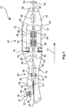
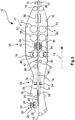
- the pourable, in particular granular, carrier material is arranged between two belt-like conveying means.
- a lower belt-like conveyor is circulating and at a defined distance from the lower conveyor an upper belt-like conveyor is moved circumferentially.
- the carrier material can be applied to the lower conveyor and then limited by the lower and the upper conveyor. By an exact scattering can be dispensed with a lateral boundary.
- the belt-like conveying means can take on two functions, namely that of a means of transport and that of a mold.
- the band-like conveying means at least in the region of the two-band press, as described below, be at least partially made of Teflon or polytetrafluoroethylene (PTFE).
- the bands may be formed entirely of polytetrafluoroethylene, or bands provided with an outer coating of polytetrafluoroethylene may be used.
- glass-fiber-reinforced plastic tapes or steel tapes with a coating of polytetrafluoroethylene can be used.
- the conveyed carrier material adheres to the conveying means and thus adversely affects the surface structure directly or by adhering material in a next cycle.
- polyterafluoroethylene is resistant to chemicals as well as against decomposition even at high temperatures, so that on the one hand a problem-free temperature treatment of the carrier material is possible and the funding is also stable for a long period of time.
- the carrier material can be freely selectable.
- the funding can go through the entire device, or can be interrupted and configured as a plurality of funding.
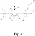
- the arrangement of the carrier material according to method step b) can be realized in particular by means of one or a plurality of scattering heads, which can carry out the carrier material defined approximately from storage containers.
- the scattering heads these may for example be part of a scattering unit and have at least one rotating scattering roller.
- a funnel may be provided which the material to be discharged defined on the spreading roller can carry.
- a doctor may further be provided which sweeps the material in recesses of the roller.
- the material can be discharged by means of a rotating brush roller from the scattering roller, where it hits against a baffle and from there slides on the conveyor.
- a spread width setting may be further provided.
- a particularly homogeneous discharge of the carrier material can take place, which can likewise lead to a homogeneous carrier with defined quality.
- a scattering head or two, three or more scattering heads can be provided.
- the carrier can be particularly tailor-made in a particularly simple manner, for example by providing a desired material mixture.
- the mixture can be easily adapted during the manufacturing process or between batches, so that a particularly large variability can be ensured.
- a mixture for the carrier material can be generated only immediately before processing, so that a negative influence on the various components with each other and a consequent reduction in the quality of the carrier produced can be prevented.
- a sensor for checking the arrangement of the carrier material between the two belt-like conveying means may be provided, for example with respect to the basis weight of the material applied or the homogeneity.
- a shaping of the carrier material arranged between the band-like conveying means takes place under the action of temperature or heat.
- this process step takes place by the acting heat or heat thus melting or softening of Support material or at least a part thereof, whereby, for example, the granules can be formed.
- it can homogeneously fill the receiving space forming between the conveying means and thus form a web-shaped carrier which can be further treated.
- the thus formed web-shaped support can be compressed simultaneously to or after process step c) following according to process step d).
- This process step can be carried out in particular in a suitable press or roller.
- the carrier can already essentially obtain its desired thickness, so that in the following processing steps only a slight compression needs to take place and thus the further steps can be particularly gentle, as will be explained in detail below.
- it can be ensured, in particular, that the temperature of the carrier has cooled down so far that a suitable compressibility can be achieved while maintaining the desired result.
- a further process step e) now further treatment of the carrier under the action of pressure using a two-band press.
- the surface properties of the carrier can be adjusted or the thickness of the carrier can be at least substantially preset.
- the previously compressed carrier can be treated under the action of pressure, wherein in particular the pressure can be selected to be low such that this compression takes place only in a very small range.
- the configuration of the processing device in this process step can be selected in particular depending on a desired setting of the compression, which can be particularly gentle and effective.
- the use of a two-belt press can be advantageous, since with such a press particularly gentle compression steps are possible and, furthermore, the surface quality or thickness of the carrier can be adjusted in a particularly effective and defined manner.
- the use of a belt press can enable high line speeds, so that the entire process can enable a particularly high throughput.
- such a belt press which usually has a rather long processing space in the conveying direction of the carrier, have a plurality of tempering zones, which may allow a temperature profile and thus an effective adjustment of the surface properties even at high line speeds, as described in detail below.
- the belt press can comprise, for example, steel strips, for example coated without coating or for instance with polytetrafluoroethylene, and can be tempered by, for example, a thermal oil heater.
- Smoothing or adjusting the surface finish may mean in this step that, although the uppermost surface is smoothed, already introduced structures or pores, however, are not or only influenced within a defined range, so that they still remain in the desired manner after this process step may be present, insofar as this is desired.
- This can be made possible in particular by the use of a belt press with a suitable temperature profile and with suitable pressure values, or by a calender, as described in detail below.
- the carrier when the carrier or carrier material is heated in preceding process steps, it may be preferable for the carrier to be cooled during or before process step e), in particular below the melting point or the softening point of a plastic constituent of the carrier material.
- the carrier can be cooled before or in the dual-band press. In this case, cooling can take place only in a limited range, so that the carrier still has a compared to the room temperature (22 ° C) increased temperature, but below the previously set elevated temperature and thereby preferably and depending on the plastic used, below the melting point or the softening point of the plastic contained in the carrier material.
- Suitable temperatures are, for example, and not limited to a range of below 130 ° C, in particular below 120 ° C, for example in a range of ⁇ 80 ° C to ⁇ 115 ° C for polyethylene.
- the above-described treatment of the carrier in method step e) takes place at a temperature T1.
- This temperature may, for example, in a range of ⁇ 150 ° C to ⁇ 190 ° C, for example from ⁇ 160 ° C to ⁇ 180 ° C, take place at about 170 ° C.
- the carrier when the carrier has a plastic component, the carrier is relatively soft in this temperature range and therefore in particular along its entire Thickness moldable, so that a compression can run under the application of low contact pressures of the two-band press particularly effective.
- This method step can thus serve, in particular, for setting or calibrating the thickness of the carrier.
- Suitable but non-limiting contact pressures for this process step include, for example, a range of ⁇ 10 kg / cm 2 to ⁇ 40 kg / cm 2 , in particular ⁇ 20 kg / cm 2 to ⁇ 30 kg / cm 2 , depending, for example, on the exact temperature selected, the material of the carrier and the desired compression factor.
- method step e) is realized by forming a compression factor K1 of the carrier.
- a compression factor K can be understood as a factor by which the thickness of the support is reduced by the treatment step.
- a thickness of 80% based on the thickness before the treatment, or the thickness was reduced by 20%. Accordingly, a compression factor K1 of 0.2 is present.
- Exemplary compression factors for method step e) are approximately in a range of> 0, for example ⁇ 0.1 to ⁇ 0.3, for example ⁇ 0.15 to ⁇ 0.25, such that the thickness decreases by one in the case of the aforementioned compression factors, for example Value that is in a range of ⁇ 10% to ⁇ 30%, in particular ⁇ 15% to ⁇ 25%, about 20%.
- the temperatures T1 and T2 relate in particular to the temperature acting on the carrier, see above that it is possible that the carrier is not or not in its entire thickness necessarily the same temperature.
- This method step thus comprises a further treatment process of the carrier under the application of pressure, which, however, can not be followed, for example, directly by method step e).
- a temperature T2 is used which is lower than the temperature T1.
- the temperatures T1 and T2 may be adjustable using mutually separate, for example, different from each other tempering and / or separate temperature control.
- the temperature T2 is preferably not adjusted by mere cooling during the treatment of the carrier by lack of heating, but rather by the defined action of a respective temperature control, such as by active cooling by a respective temperature control.
- the temperature can be specifically defined, which can allow a defined treatment result and good adaptability.
- the temperature T2 during process step f) can, for example, using a carrier having a plastic component, allow the viscosity of the carrier is lower or that the carrier is harder than at the temperature T1 used in process step e).
- This method step f) can thus serve in particular to no longer significantly compress the carrier or to reduce the thickness of the carrier, but rather to adjust the surface properties of the carrier and therefore to mainly smooth the carrier or its surface.
- a compression can take place, which may be in a range of in particular> 0%, but which may be limited to values in a range of ⁇ 20%, the support thus having a thickness of 80% with respect to its thickness before process step f).
- the carrier may be compressed by a value that is approximately in a range of ⁇ 3% to ⁇ 20%, about 10%. With respect to the compression factor K2 this is thus less than the compression factor K1.
- Exemplary compression factors are approximately in a range of> 0 to ⁇ 0.2, for example in a range of> 0.03 to ⁇ 0.15, approximately ⁇ 0.05 to ⁇ 0.12 ⁇ , for example, 0.1.
- the contact pressures for this method step are selected in a suitable manner, in particular as a function of the desired compression factor K2 to be achieved, of the carrier material and of the set temperature.
- a temperature can be set in this process step f), which is above the crystallization temperature of the plastic.
- LLDPE linear polyethylene
- the temperature T2 can be set such that it lies in a range of ⁇ 100 ° C to ⁇ 150 ° C, for example, of 120 ° C.
- a further cooling of the web-shaped carrier then optionally takes place.
- the support can be cooled to a temperature which corresponds to the room temperature or, purely by way of example, lies in a range of up to 20 ° C. above it.
- the carrier is heated to a temperature which is above the crystallization temperature of a plastic present in the carrier. Subsequently, the support can in turn be cooled below the crystallization temperature, for example to room temperature (22 ° C.).
- the carrier is heated again to a temperature which is above the crystallization temperature of the plastic of the carrier material after treating the carrier according to method step f) and in particular after cooling of the carrier according to method step f), the properties of the carrier can be further improved become.
- the carrier can have improved stability properties, in particular with regard to its mechanical and / or thermal and / or chemical resistance. As a result, the quality of the carrier can be further improved.
- the crystallization temperature is, in particular, the temperature to which the polymer must be heated in order then to be able to form crystals on cooling.
- crystallization begins upon cooling of the polymer at a temperature which may be below the melting temperature and optionally above the glass transition temperature. Accordingly, heating to a temperature below the melting temperature of the respective plastic or to a temperature below the melting temperature may suffice.
- heating to a temperature in a range of ⁇ 100 ° C to ⁇ 150 ° C, for example, 120 ° C may be sufficient.
- heating to a temperature in a range of ⁇ 160 ° C to ⁇ 200 ° C, for example, 180 ° C may be sufficient.
- the duration of the corresponding heating can thus depend, in a manner understandable to the person skilled in the art, on the travel speed of the carrier, its thickness and the temperature to be set.
- the carrier After cooling of the carrier produced, the carrier can first be stored in web-like form or as an isolated plate-like carrier as an intermediate and the process can initially be completed. Preferably, however, immediately follow further treatment steps, which may be feasible without grinding, in particular in order to process the provided support so as to produce a finished panel, as explained in detail below.
- the method comprises the further following method steps in order to provide the support with a decoration and to coat it with a protective layer.
- the subsequent steps are preferably carried out directly with the web-shaped carrier produced.
- the web-shaped carrier is first subdivided into a plurality of plate-shaped carriers before a suitable one of process steps h) to j) and / or the plate-shaped carrier is further processed by the corresponding following method steps.
- the following explanations apply to both alternatives, with a further discussion of treatment of the carrier for the sake of simplicity.
- a decorative substrate it is furthermore possible if appropriate for a decorative substrate to be applied to at least one partial region of the carrier.
- a primer can be applied in particular for printing processes as a decorative substrate, for example in a thickness of ⁇ 10 ⁇ m to ⁇ 60 ⁇ m.
- the primer used may be a liquid radiation-curing mixture based on a urethane or a urethane acrylate, optionally with one or more of a photoinitiator, a reactive diluent, a UV stabilizer, a rheology agent such as a thickener, radical scavenger, leveling agent, defoamer or preservative, pigment and / or or a dye.
- a primer it is possible to apply the decor to a decorative paper which can be printed with a corresponding decor, which can be provided as a connection means, for example, by means of a resin layer previously applied to the support.
- a resin layer is suitable both for flexo printing, offset printing or screen printing methods, and in particular for digital printing techniques, such as inkjet method or laser printing method.
- a resin composition having as a resin component at least one compound selected from the group consisting of melamine resin, formaldehyde resin, urea resin, phenol resin, epoxy resin, unsaturated polyester resin, diallyl phthalate, or mixtures thereof.
- the resin composition can be applied, for example, in an application amount of between ⁇ 5 g / m 2 and ⁇ 40 g / m 2 , preferably ⁇ 10 g / m 2 and ⁇ 30 g / m 2 .
- a paper or nonwoven having a grammage of between ⁇ 30 g / m 2 and ⁇ 80 g / m 2 , preferably between ⁇ 40 g / m 2 and ⁇ 70 g / m 2 may be applied to the plate-shaped carrier.
- a decoration which imitates a decorative pattern can be applied to at least one subregion of the carrier.
- the decor can be applied by the so-called direct printing.
- direct printing in the context of the invention, the application of a decoration directly on the Carrier of a panel or on a carrier applied to the non-printed fiber material layer or a decorative background understood.
- Different printing techniques such as flexographic printing, offset printing or screen printing can be used.
- digital printing techniques for example, inkjet method or laser printing method can be used.
- the decorative layers can also be formed from a particular radiation-curable ink and / or ink.
- a UV-curable ink or ink may be used.
- the decorative layers can each be applied in a thickness in a range of ⁇ 5 ⁇ m to ⁇ 10 ⁇ m.
- a color and / or structure positive image also apply a corresponding negative image of the decor template.
- the color impression of, for example, a grain can be reversed by the use of digital data, so that a negative arises with respect to the color or, in particular, lighter and darker areas.
- the same is possible in addition to the color impression also for the applied structure, so that also with respect to the structural design, a negative is feasible. Even such effects can be easily integrated into a production process on the basis of digital three-dimensional data without any lead time or conversions.
- a protective layer on at least one partial area of the decoration.
- a layer for protecting the applied decoration can, in particular, be used as a wearing or covering layer above the decorative layer in FIG be applied to a subsequent process step, which protects the decorative layer in particular from wear or damage by dirt, moisture or mechanical effects such as abrasion.
- the wear and / or cover layer is laid on the printed support as a pre-produced overlay layer, for example based on melamine, and connected thereto by pressure and / or heat.
- a radiation-curable composition such as, for example, a radiation-curable lacquer, such as an acrylic lacquer
- a radiation-curable lacquer such as an acrylic lacquer
- the wear layer hard materials such as titanium nitride, titanium carbide, silicon nitride, silicon carbide, boron carbide, tungsten carbide, tantalum carbide, aluminum oxide (corundum), zirconium oxide or mixtures thereof, to increase the wear resistance of the layer.
- the application can be applied for example by means of rollers, such as rubber rollers or by means of pouring devices.
- cover layer can first be partially cured and subsequently a final coating with a urethane acrylate and a final curing, such as with a gallium radiator, are performed.
- the cover and / or wear layer may include means for reducing the static (electrostatic) charge of the final laminate.
- the cover and / or wear layer has compounds such as choline chloride.
- the antistatic agent may, for example, in a concentration between ⁇ 0.1 wt .-% and ⁇ 40.0 wt .-%, preferably between ⁇ 1.0 wt .-% and ⁇ 30.0 wt .-% in the cover and / or composition for forming wear layer.
- the carrier plate already has a structuring and alignment of a printing tool for applying the decor and the support plate to each other in dependence on by means of the optical process detected structuring of the support plate.
- a necessary relative to the orientation relative movement between the pressure tool and support plate to each other by a displacement of the support plate or by a displacement of the pressure tool it may be provided that structuring of the decorative panels takes place after application of the covering and / or wearing course.
- a curable composition is applied as cover and / or wear layer and a curing process takes place only to the extent that only partial hardening of the cover and / or wear layer takes place.
- a desired surface structure is impressed by means of suitable tools, such as a hard metal structural roller or a stamp.
- the embossing is done in accordance with the applied decor.
- a matching with the decor surface structuring is introduced.
- the surface of the decorative panel has a haptic perceptible structure, which in shape and their pattern corresponds to the applied decor, so as to obtain the most faithful reproduction of a natural material also in terms of haptics.
- a counter-pull can be applied on the side opposite the decorative side. It is particularly preferred that the counter-pull is applied in a common calendering with the paper or non-woven on the decorative side.
- the edge regions of the panel can be structured or profiled, in order to provide in particular detachable connecting elements.
- a profiling it can be provided that a decorative and / or functional profile is introduced by means of suitable material-removing tools at least into a part of the edges of the decorative panel.
- a functional profile is understood, for example, to mean the introduction of a tongue and / or groove profile into an edge in order to make decorative panels connectable to each other via the introduced profilings.
- elastic materials are advantageous, since such profiles alone can be produced by them, which are particularly easy to handle and stable. In particular, no further materials are necessary to produce the fasteners.
- the method described above makes it possible to produce a panel with a carrier which has a particularly defined and particularly smooth surface. This may be particularly advantageous for the application of further layers to the carrier, such as a printing substrate or a decorative layer, in particular using a direct printing process.
- the support material can be chosen particularly freely and, in particular, support materials can be used which are suitable for the panel to be produced may have particularly advantageous properties. For example, it is possible to produce particularly high-quality panels which can meet the highest requirements in terms of appearance and stability. In this case, a production can be particularly effective and inexpensive.
- the method for producing a carrier that can be used in the method for producing a wall and floor panel can be advantageous, in particular in the context of the present inventive method for producing wall and floor panels, since it enables particularly high line speeds, which far exceed those of the prior art Line speeds known to the art, as a feed rate of the carrier or the conveying means, may be for the manufacture of a panel.
- Line speeds of up to 15 m / min can be achieved, in particular by the use of a two-belt press, whereby values of 6 m / min or more can also be possible for materials which are problematic in this respect.
- a very accurate thickness can be achieved, in particular for panel support materials, wherein, for example, thickness tolerances in a range of 0.1 mm or less can be achieved.
- a carrier produced by the above-described method can furthermore have a particularly uniform thickness, which allows a particularly defined and reproducible product and thus a particularly high quality.
- This quality can be further increased by the fact that following a first treatment of the carrier in the two-band press according to method step e) is followed by a further treatment step f).
- this treatment step is aimed less at compressing than at a targeted smoothing of the surface. This can Not only the thickness of the carrier but also its surface properties can be adjusted specifically, which can lead to a particularly high quality product.
- the method steps e) and f) are carried out in a common dual-band press.
- the method steps e) and f) can thus be carried out in a common pressing device, which can make the equipment of a system for carrying out the method in this embodiment particularly cost-effective.
- temperature control can be arranged and act so that within the two-band press two different temperature levels, in particular in different in the direction of travel of the carrier successively arranged temperature ranges of the two-band press are adjustable so that the carrier can be treated first at the temperature T1 and then at the temperature T2 ,
- the different compression factors K1 and K2 can thus be made possible, in particular, by setting the corresponding temperatures in different treatment areas or temperature ranges of the dual-band press.
- the pressing device or the two-band press has a variable pressure profile, for example in an area starting with 6 mm and ending with 4.1 mm, for example starting with 5.9 mm and ending with 5.3 mm, for example with intermediate stages of 5 , 7mm and 5.5mm.
- different compression factors K1 and K2 can also be made possible.
- the method steps e) and f) are carried out in two separate pressing devices.
- the pressing means such as those directly with the carrier in Contact coming components, adapted to the particular conditions, such as in particular set temperature and contact pressure.
- temperatures T1 and T2 can be set in a particularly defined manner, since an interaction of the temperature control means on a respective other area, that is to say an effect of the temperature control means acting on the temperature T1 to the range to be set with the temperature T2, or vice versa, is further reduced or completely reduced can be excluded.
- the compression factors K1 and K2 in this embodiment can be adjusted in particular by adjusting the respective temperature and the respective contact pressure.
- the carrier between the steps e) and f) is stored and after step e) and before step f) an intermediate product is formed which, for example, starting with step f) to the finished panel on can be processed.
- This can result in a high product variability, since the intermediates are customizable, for example with respect to the smoothness of the surface of the carrier for different products.
- method step f) is carried out in a two-band press or in a calender.
- pressing means can be carried out an advantageous smoothing.
- a long treatment gap by means of which an equally long treatment period of the carrier can be made possible, can be made possible by the dual-band press.
- a particularly smooth surface can be made possible.
- using a calender it is particularly easy to allow sufficient action to be exerted on the support even at comparatively low temperatures.
- process step f) in particular comprise a metal strip, such as a steel strip, in order to allow a suitable pressing pressure, even at the selected temperature range.
- process step e) may already be sufficient due to the relatively higher temperature, a plastic band.
- a carrier material based on a plastic or a wood-plastic composite material can be provided.
- the carrier plate made of a thermoplastic, elastomeric or thermosetting plastic may be at least partially formed.
- recycled materials from the materials mentioned can be used in the context of the method according to the invention.
- Thermoplastic plastics such as polyvinyl chloride (PVC), polyolefins (for example polyethylene (PE), polypropylene (PP), polyamides (PA), polyurethanes (especially in the context of a WPC material or a pure plastic material) may be used as the preferred sheet material.
- PU polystyrene
- ABS acrylonitrile-butadiene-styrene
- PMMA polymethylmethacrylate
- PC polycarbonate
- PET polyethylene terephthalate
- PEEK polyetheretherketone
- plasticizers which are approximately in a range from> 0% by weight to ⁇ 20% by weight, in particular ⁇ 10% by weight, preferably ⁇ 7% by weight, for example may be present in a range of ⁇ 5 wt .-% to ⁇ 10 wt .-%.
- a suitable plasticizer comprises, for example, the softener marketed under the trade name "Dinsch" by BASF. Further may be substituted for conventional plasticizer copolymers such as acrylates or methacrylates.
- the carrier in or in front of the dual-band press in this embodiment, the carrier can be cooled to a temperature below the melting temperature of the plastic component.
- thermoplastics also offer the advantage that the products made from them can be recycled very easily. Recycled materials from other sources can also be used. This results in a further possibility for reducing the production costs.
- Such carriers are very elastic or resilient, which allows a comfortable impression when walking and also can reduce the noise occurring when walking in comparison to conventional materials, thus an improved footfall sound can be realized.
- the above-mentioned carriers offer the advantage of good water resistance since they have a swelling of 1% or less. This is true in a surprising way in addition to pure plastic substrates for WPC materials, as they are explained in detail below.
- polyvinyl chloride may be advantageous.
- the carrier material may comprise or consist of wood-polymer materials (WPC).
- WPC wood-polymer materials
- a wood and a polymer may be suitable, which may be present in a ratio of 40/60 to 70/30, for example 50/50.
- Polypropylene, polyethylene or a copolymer of the two abovementioned materials can be used as polymer constituents, wherein wood flour can furthermore be used as wood constituent.
- Such materials offer the advantage that they can be formed into a carrier even at low temperatures, such as in a range of ⁇ 180 ° C to ⁇ 200 ° C in the above-described method, so that a particularly effective process control, such as with exemplary line speeds in one Range of 6m / min, can be enabled.
- a WPC product with a 50/50 distribution of the wood and polymer fractions possible with an exemplary product thickness of 4.1mm, which can allow a particularly effective manufacturing process.
- very stable panels can be produced which furthermore have high elasticity, which can be advantageous in particular for an effective and cost-effective design of connecting elements on the edge region of the carrier and furthermore with regard to footfall sound insulation.
- the aforementioned good water compatibility can be made possible with a swelling of less than 1% in such WPC materials.
- WPC materials for example, stabilizers and / or other additives, which may preferably be present in the plastic content.
- the carrier material comprises a PVC-based material or consists of PVC, for example.
- PVC-based carrier materials can be used in a particularly advantageous manner for high quality panels, which are easily used even in wet rooms.
- PVC-based carrier materials are also suitable for a particularly effective production process, since here line speeds of 8 m / min with an exemplary product thickness of 4.1 mm may be possible, which may allow a particularly effective production process.
- such carriers have an advantageous elasticity and water compatibility, which can lead to the aforementioned advantages.
- mineral fillers can be beneficial.
- Talc or talc or else calcium carbonate (chalk), aluminum oxide, silica gel, quartz flour, wood flour, gypsum are particularly suitable here.
- chalk may be provided.
- the proportion of mineral fillers, such as talc may be in a range of ⁇ 30 wt .-% to ⁇ 80 wt .-%, for example from ⁇ 45 wt .-% to ⁇ 70 wt .-% lie.
- the fillers may be colored in a known manner.
- the plate material has a flame retardant.
- the plate material has a flame retardant.
- the carrier material consists of a mixture of a PE / PP block copolymer with wood.
- the proportion of PE / PP block copolymer and the proportion of wood between ⁇ 45 wt .-% and ⁇ 55 wt .-% may be.
- the support material can have between ⁇ 0% by weight and ⁇ 10% by weight of other additives, such as flow aids, heat stabilizers or UV stabilizers.
- the particle size of the wood is between> 0 ⁇ m and ⁇ 600 ⁇ m with a preferred particle size distribution D50 of ⁇ 400 ⁇ m.
- the support material may have wood with a particle size distribution D10 of ⁇ 400 ⁇ m.
- the particle size distribution is based on the volumetric diameter and refers to the volume of the particles.
- the carrier material is particularly preferably provided as a granulated or pelletized pre-extruded mixture of a PE / PP block copolymer with wood particles of the specified particle size distribution.
- the Granules and / or the pellets may preferably have a particle size in a range of ⁇ 400 ⁇ m to ⁇ 10 mm, preferably ⁇ 600 ⁇ m to ⁇ 10 mm, in particular ⁇ 800 ⁇ m to ⁇ 10 mm.
- the carrier material may be in the form of granules and may have approximately a cylindrical shape. Further, regardless of the shape but exemplified in the cylindrical shape, the granule particles may have a diameter in a range of 2-3mm, for example, 2 or 3mm, and a length of 2-9mm, for example, 2-7mm or 5-9mm.
- the carrier material consists of a mixture of a PE / PP polymer blend with wood.
- the proportion of PE / PP polymer blend and the proportion of wood between ⁇ 45 wt .-% and ⁇ 55 wt .-% may be.
- the support material can have between ⁇ 0% by weight and ⁇ 10% by weight of other additives, such as flow aids, heat stabilizers or UV stabilizers.
- the particle size of the wood is between> 0 ⁇ m and ⁇ 600 ⁇ m with a preferred particle size distribution D50 of ⁇ 400 ⁇ m.
- the support material may have wood with a particle size distribution D10 of ⁇ 400 ⁇ m.
- the particle size distribution is based on the volumetric diameter and refers to the volume of the particles.
- the carrier material is provided as granulated or pelletized pre-extruded mixture of a PE / PP polymer blend with wood particles of the specified particle size distribution.
- the granules and / or the pellets may preferably have a particle size in a range of ⁇ 400 ⁇ m to ⁇ 10 mm, preferably ⁇ 600 ⁇ m to ⁇ 10 mm, in particular ⁇ 800 ⁇ m to ⁇ 10 mm.
- the carrier material consists of a mixture of a PP homopolymer with wood.
- the proportion of the PP homopolymer and the Wood content between ⁇ 45 wt .-% and ⁇ 55 wt .-% are.
- the components wood and polypropylene may be present in a ratio of 0.5: 1 to 1: 0.5, about 1: 1.
- the support material can have between ⁇ 0% by weight and ⁇ 10% by weight of other additives, such as flow aids, heat stabilizers or UV stabilizers.
- the particle size of the wood is between> 0 ⁇ m and ⁇ 600 ⁇ m with a preferred particle size distribution D50 of ⁇ 400 ⁇ m.
- the support material may have wood a particle size distribution D10 of ⁇ 400 ⁇ m.
- the particle size distribution is based on the volumetric diameter and refers to the volume of the particles.
- the carrier material is particularly preferably provided as granulated or pelletized pre-extruded mixture of a PP homopolymer with wood particles of the stated particle size distribution.
- the granules and / or the pellets may preferably have a particle size in a range of ⁇ 400 ⁇ m to ⁇ 10 mm, preferably ⁇ 600 ⁇ m to ⁇ 10 mm, in particular ⁇ 800 ⁇ m to ⁇ 10 mm.
- the carrier material consists of a mixture of a PVC polymer with chalk.
- the proportion of the PVC polymer and the amount of chalk can be between ⁇ 45% by weight and ⁇ 55% by weight.
- the support material can have between ⁇ 0% by weight and ⁇ 10% by weight of other additives, such as flow aids, heat stabilizers or UV stabilizers.
- the particle size of the chalk is between> 0 ⁇ m and ⁇ 1000 ⁇ m, for example between ⁇ 800 ⁇ m and ⁇ 1000 ⁇ m with a preferred particle size distribution D50 of ⁇ 400 ⁇ m, for example of ⁇ 600 ⁇ m.
- the carrier material may have chalk with a particle size distribution D10 of ⁇ 400 ⁇ m, for example of ⁇ 600 ⁇ m.
- the particle size distribution is based on the volumetric diameter and refers to the volume of the particles.
- the carrier material is particularly preferably provided as granulated or pelletized pre-extruded mixture of a PVC polymer with chalk of the specified particle size distribution.
- the granules and / or the pellets may preferably be about a particle size in a range of ⁇ 400 ⁇ m to ⁇ 10mm, preferably ⁇ 600 ⁇ m to ⁇ 10mm, in particular ⁇ 800 ⁇ m to ⁇ 10mm, for example ⁇ 1000 ⁇ m to ⁇ 10mm.
- the carrier material consists of a mixture of a PVC polymer with wood.
- the proportion of PVC polymer and the wood content between ⁇ 45 wt .-% and ⁇ 55 wt .-% are.
- the support material can have between ⁇ 0% by weight and ⁇ 10% by weight of other additives, such as flow aids, heat stabilizers or UV stabilizers.
- the particle size of the wood is between> 0 ⁇ m and ⁇ 1000 ⁇ m, for example between ⁇ 800 ⁇ m and ⁇ 1000 ⁇ m with a preferred particle size distribution D50 of ⁇ 400 ⁇ m, for example of ⁇ 600 ⁇ m.
- the carrier material may have a particle size distribution D10 of ⁇ 400 ⁇ m, for example of ⁇ 600 ⁇ m.
- the particle size distribution is based on the volumetric diameter and refers to the volume of the particles.
- the carrier material is particularly preferably provided as a granulated or pelletized pre-extruded mixture of a PVC polymer with wood particles of the specified particle size distribution.
- the granules and / or the pellets may preferably have a particle size in a range of ⁇ 400 ⁇ m to ⁇ 10 mm, preferably ⁇ 600 ⁇ m to ⁇ 10 mm, in particular ⁇ 800 ⁇ m to ⁇ 10 mm, for example ⁇ 1000 ⁇ m to ⁇ 10 mm.
- the particle size distribution it is possible to resort to the generally known methods, such as, for example, laser diffractometry, with which particle sizes ranging from a few nanometers to several millimeters can be determined.
- This method can also be used to determine D50 or D10 values, which are 50% and 10% of the measured particles smaller than the specified value.
- the carrier is cooled between the method steps e) and f) to a temperature T3, wherein T3 ⁇ T1 and wherein T3 ⁇ T2.
- the carrier is cooled completely, initially, to a temperature T3 which is below the processing temperature T1, which is used in method step e), and which is also below the processing temperature T2, which is used in method step f).
- the temperature T3 can be in a range from ⁇ 30 ° C to ⁇ 100 ° C, for example from ⁇ 40 ° C to ⁇ 90 ° C, approximately to ⁇ 60 ° C to ⁇ 70 ° C.
- Cooling can advantageously be realized stepwise by reducing the temperature not continuously but successively or stepwise.
- a three-stage cooling process may be performed wherein the temperature is in no way limiting, for example, to a range of ⁇ 75 ° C to ⁇ 100 ° C, for example 90 ° C, then to a range of ⁇ 50 ° C to ⁇ 74 ° C, For example, 60 ° C, and then to a range of ⁇ 30 ° C to ⁇ 49 ° C, for example, 40 ° C is cooled.
- the stepwise cooling may include that the carrier is held for a defined period of time in the said temperature ranges and / or at a constant temperature.
- This embodiment may be particularly preferred, for example, if the carrier between the steps e) and f) is stored, since in this case, a stacking of the carrier with cooled temperature can be significantly gentler and the carrier can be more stable with a relatively low temperature than with a comparatively higher temperature.
- a step-by-step cooling process may be advantageous since, in this way, deformation of the support can be further reduced or completely prevented.
- this can be done by a cooling circuit which can be configured in particular in combination with the other passages for cooling the carrier as a closed cooling circuit.
- the support is heated before or during method step f) to a temperature which is above the crystallization temperature of a plastic present in the carrier.
- a surface can be produced which has a high smoothness.
- the properties of the carrier can be further improved.
- the carrier can have improved stability properties, in particular with regard to its mechanical and / or thermal and / or chemical resistance. As a result, the quality of the carrier can be further improved.
- a release agent is arranged such that it is at least in the two-band press between the carrier and a conveyor, such as the upper conveyor, preferably between the carrier and two funding arranged ,
- adhesion of the carrier to a conveyor can be prevented particularly effectively.
- the release agent may, for example, be rolled up on a first roll and guided together with the carrier through the two-band press and optionally the further pressing unit, such as the calender, before it is rolled up onto another roll.
- the release agent preferably moves at the same speed as the carrier.
- the release agent may comprise a release paper, such as an oiled paper.
- a so-called wax paper called oil paper can be understood in a conventional manner, for example, a wood-free paper, which is a Organic substance, such as an oil or wax or paraffin, for example, is impregnated with this.
- a fiber material can be incorporated into the carrier.
- the fiber material can be incorporated into the carrier in process step b).
- a fiber material in particular as a fiber material web, be wound on a roll and unwound by means of a unwinding station for unwinding the fiber material and are guided between the two belt-like conveying means to insert the fiber material.
- a glass fiber fleece can be used.
- a carrier can be produced with a particularly high load-bearing capacity or stability, since the strength of the carrier can be significantly increased by the incorporated fiber material.
- the carrier can be particularly tailored in this embodiment, since, for example, by providing a plurality of scattering units, as explained above in detail, the carrier material, for example, above and below the web can be adjusted as desired. Furthermore, a still tailor-made solution can be made possible by the provision of a plurality of fibrous material webs, wherein the carrier material can in turn be variable or adaptable as desired.
- process step d) is carried out using an S-roll.
- an S-roll as a compression unit, desired compression can be enabled with a simple and inexpensive means defined even at high line speeds.
- the roller may be adjustable, for example, in the direction of the continuous carrier material.
- the S-roll for example, only comprise a roller which exerts a force only in combination with a counterforce by the belt tension of the conveyor.
- one or a plurality of counter-rollers may be provided, which apply the corresponding counterforce.
- an S-roll can be understood to mean a roll which is arranged in such a way that the support circulates in an S-shape, as is known to the person skilled in the art and described in detail below with reference to the figures.
- a temperature gradient can be adjusted. This can be made possible in particular by a temperature gradient in a direction perpendicular to the conveying direction.
- a particularly high line speed can be allowed because about a particularly fast heating can be made possible, which just allows a high line speed.
- too high a temperature effect on the carrier material can continue to be prevented, which can prevent damage and enable a particularly high quality.
- a degassing can be improved and accelerated upon heating of the support material, which in turn allows a high line speed and also can provide a particularly high stability and quality by preventing gas inclusions.
- the region below the carrier material can be heated higher than the region above the carrier material, that is to say have a higher temperature than an upper temperature-controlling element, for example, than an upper tempering element.
- a temperature gradient in a range of 50 ° C may be advantageous.
- the device thus serves to produce from a particular granular carrier material a web-shaped carrier.
- two belt-like conveying means are provided, which can initially transport the carrier material or optionally in the course of the process, the carrier formed therefrom.
- the conveying means can each form a circulating conveyor belt such that a processing gap is formed between the upper run of a lower conveyor belt and the lower run of an upper conveyor belt.
- a discharge unit which can arrange the carrier material between the conveying means.
- the discharge unit may scatter the carrier material on the lower conveyor belt, as described in detail above.
- the apparatus further comprises a forming unit for forming a web-shaped carrier from the carrier material.
- a forming unit for forming a web-shaped carrier from the carrier material.
- the molding unit may, for example, comprise two plate-shaped molding devices, as described above.
- a pressing device is also provided. This may in particular be an S-roll, as described above with reference to the method.
- a two-belt press is provided as a pressing means for treating the carrier under the action of pressure at a temperature T1.
- the carrier can be compressed at the temperature T1 by applying a pressure such that the carrier is compressed to form a compression factor K1.
- a further pressing device may be provided in the transport direction of the carrier after the two-band press. Either in this further pressing device or in the two-band press, the carrier is treated at a temperature T2, wherein a compression is achieved with a lower compression factor K2 compared to K1.
- the treatment of the carrier at the temperature T2 substantially only slightly compressing but optionally rather a smoothing of the corresponding carrier surface.
- This can be realized, for example, in such a way that two different temperature ranges are present in the two-band press itself, for example by the provision in FIG Transport direction of the carrier successively arranged tempering, or by the provision of an additional pressing device, which can set a low temperature and different pressing pressure compared to the two-band press.
- the process can have further process steps in order to obtain the finished wall or floor panel.
- the device 10 according to FIG. 1 comprises first two circumferential band-like conveying means 12, 14, which are guided in particular by deflection rollers 16 such that between them a receiving space 18 or machining gap for receiving and processing a provided pourable, in particular granular carrier material 20, such as based on a plastic, such as having PVC , or a wood-plastic composite material, comprising for example wood and PP, PE or a block copolymer comprising PP and PE, or based on an HDF material, or based on PVC.
- the conveying means 12, 14 may be at least partially made of polytetrafluoroethylene, for example coated therewith.
- the conveying means 12, 14 may be at least partially roughened or structured, in particular on their side facing the receiving space 18. Further, the conveying means 12, 14 may have a width in a range of about 1.5 m.
- a discharge unit 22 is provided with one or a plurality of discharge heads 24, through which the carrier material 20 on the lower conveyor 14 can be arranged.
- the discharge heads 24 may in this case comprise a funnel 25, which applies the carrier material 20 to corresponding scattering rollers 26, whereupon the carrier material 20 can be scattered onto the lower conveying means 14.
- a sensor for checking the arrangement of the carrier material 20 between two belt-like conveying means 12, 14 may be provided.
- the sensor may in particular be coupled to the discharge unit 22 in order to directly correct a potentially inaccurate filling of the receiving space 18.
- vibrators may also be provided. These can act approximately on the lower conveyor 14 and be arranged, for example, under the lower conveyor 14, so that the carrier material 20 is finely distributed.
- a device for introducing a fiber material into the receiving space 18 and thus be provided in the carrier can be designed like a belt and unwound from a roll.
- the fiber material may be arranged approximately between two discharge heads 24 in order, for example, to be able to arrange a different material above and below the fiber material.
- the fiber material can be introduced, for example, such that above and below the fiber material, a desired amount of support material 20 is located.
- a molding unit 28 is further provided, which is designed, the carrier material 20 under the action of temperature or heat to fuse the carrier material 20 to form a web-like or web-like carrier 36 shape.
- the molding unit 28 can have approximately two plate-like molding devices 30, 32, which can be heated by one or two heating devices 34, for example by means of a thermal oil.
- the support material 20 may be heated until, depending on the melting point of the support material 20 or a part thereof, a temperature of, for example and depending on the material used, such as PVC or a WPV material, ⁇ 180 ° C to ⁇ 200 ° C has reached.
- the molding unit 28 or the molding devices 30, 32 can be heated, for example to a temperature of up to 250 ° C.
- one or a plurality of independently adjustable heating areas can be provided for setting a temperature gradient.
- the entire shaping devices 30, 32 which may have a length of several meters, may be heatable, or only part of them may be heatable.
- the molding unit 28 may in particular have a parallel gap, which may be formed by the plate-like molding devices 30, 32.
- an inlet mouth can be provided at the inlet through a conical shape to allow an improved inlet of the carrier material 20.
- the force acting on the carrier material 20 may be fed in a range from> 0 kg / m 2, up to ⁇ 1 kg / m 2.
- a uniform pressurization without the provision of a pressure profile or a pressure gradient can be provided.
- the lower former 32 is longer than the upper former 30 and also begins before the upper. It can thereby be achieved that processing only takes place when the carrier material 20 and optionally the Foil material already melted or at least melted and at least partially softened. As a result, a particularly defined shaping process can be made possible.
- the pressing device 38 may for example comprise an S-roll, which in detail in the FIG. 3 is shown.
- the S-roll can be moved substantially perpendicular to the surface of the carrier 36 and thus to the direction of travel of the carrier 36, as indicated by the arrow 58, so that the desired pressures can be particularly advantageous adjustable.
- the pressing device 38 may, for example, on the carrier 36 exert a pressure that may be in a range of ⁇ 1kg / m 2 to ⁇ 3kg / m 2 .
- the S-roll comprises a main roller 60, which acts on the web-shaped carrier 36.
- the belt tension may be sufficient as a back pressure, but it is preferred that at least one counter-pressure roller 62 is provided.
- two pairs of calender rolls 64 and, optionally, deflection rolls 66 can also be provided, which can furthermore provide for a suitable strip tension.
- the web-like carrier 36 is guided around the guide rollers 66 and the main roller 60 twice S-shaped, which guide the term S-roller conditional.
- the main roller 60 may be wrapped by the sheet-shaped carrier 36 in a range of about 50% or more.
- the temperature of the carrier 36 further corresponds to an inlet to the pressing device 38, in particular the temperature present at the output from the molding unit 28.
- the pressing device 38 can be operated at a temperature which lies in a range of ⁇ 130 ° C to ⁇ 200 ° C, for example in a range of ⁇ 160 ° C to ⁇ 200 ° C, for example, of 180 ° C.
- the carrier 36 is subsequently guided to a further pressing device 40.
- a further tempering device 42 such as a heater, such as an IR heater, or preferably a cooling device to cool the support 36 may be provided between the pressing means 38, 40.
- the carrier 36 can also be cooled by a heating device, insofar as it transmits a temperature to the carrier, which is below the carrier temperature present in the tempering device 42 before the inlet, but above the room temperature.
- this advantageously may be a two-belt press, which in particular may comprise bands 44, 46, such as steel bands or plastic bands, which may be coated on the side facing the carrier 36 with polytetrafluoroethylene (Teflon) and the bands 44, 46 of the two-band press can be guided by deflection rollers 48, 50.
- the deflection rollers 48, 50 may be heated or advantageously cooled, for example by means of a thermal oil temperature control and / or the rollers on the same side of the gap may be arranged at a distance in a range of ⁇ 1m to ⁇ 2m, for example 1.5m from each other wherein the bands 44, 46 may have a width in a range of about 1.5 meters.
- the carrier 36 located between the conveying means 12, 14 is guided between the deflection rollers 48, 50 and thus between the belts 44, 46, in particular steel belts.
- each pressing and / or tempering 52, 54 are provided, with which the carrier 36 can be cooled and optionally heated. These can both heat, cool and slightly compress the conveyors 12, 14 and thus the carrier 36.
- an air-cooling can be provided and a plurality of rollers, which can enable an intermittent pressing.
- a temperature T1 of the carrier 36 can be set, which is in a range of ⁇ 150 ° C to ⁇ 190 ° C, for example from ⁇ 160 ° C to ⁇ 180 ° C, approximately at 170 ° C.
- a compression factor K1 of the carrier can thereby be made possible that lies in a range of ⁇ 0.1 to ⁇ 0.3, for example ⁇ 0.15 to ⁇ 0.25, so that the thickness in the case of the aforementioned compression factors is, for example decreases by a value ranging from ⁇ 10% to ⁇ 30%, in particular ⁇ 15% to ⁇ 25%, about 20%.
- a temperature T2 of the carrier 36 can be set, which is in a range ⁇ 100 ° C to ⁇ 150 ° C, for example, of 120 ° C ,.
- a compression factor K2 of the carrier can thereby be made possible that lies in a range of> 0 to ⁇ 0.2, for example in a range of> 0.03 to ⁇ 0.15, approximately ⁇ 0.05 to ⁇ 0, 12 ⁇ , for example at 0.1, so that the thickness in the aforementioned compression factors, for example, decreases by a value ranging from ⁇ 3% to ⁇ 15%, in particular ⁇ 5% to ⁇ 12%, about 10%.
- the temperature control devices 52, 54, 55, 57 for setting the temperature T1 and / or T2 can be designed, for example, as an NIR radiator or can be fed by or have a heating circuit.
- different temperature zones can be set in the dual-band press, so that the carrier 36 is first compressed at the temperature T1 with a compression factor K1, and further wherein the carrier 36 is compressed at the temperature T2 with a compression factor K2, where K1 ⁇ K2.
- the surface of the carrier, in particular the upper surface is not significantly compressed but rather smoothed.
- FIG. 2 Corresponding may, as in FIG. 2 is shown, can be realized by a further pressing unit 49 is provided behind the two-band press in the direction of travel of the carrier 36.
- a further two-belt press may be provided, or, as in the FIG. 2
- a calender may be provided with the calender rolls 51, 53 to smooth the carrier 36 or its surface.
- a cooling device 56 can be arranged, by means of which the carrier 36 can be cooled to a temperature which, for example, lies in a range of ⁇ 35 ° C.
- the cooling device 56 may be based, for example, on a water cooling system and include a plurality of cooling zones, in order to allow a defined cooling using precisely customizable cooling programs.
- the length of the cooling zone can correspond to the effective length of the pressing device 40. After the cooling device 56 may still be provided another cooling belt.
- the support 36 which may have approximately a final thickness in a range of ⁇ 3 mm to ⁇ 5 mm, for example 4.1 mm, can be further treated directly, or be stored, for example as a web-shaped support 36 or as an already singly plate-shaped support.
- At least one heating device 59 or two heating devices 59 may be provided, which may be arranged above and optionally below the carrier 36 and through which the carrier 36 is heated. This makes it possible for the support 36 to be heated to a temperature which is above the crystallization temperature of a plastic present in the support 36 after process step f), cooling being able to follow.
Landscapes
- Life Sciences & Earth Sciences (AREA)
- Engineering & Computer Science (AREA)
- Wood Science & Technology (AREA)
- Forests & Forestry (AREA)
- Manufacturing & Machinery (AREA)
- Architecture (AREA)
- Civil Engineering (AREA)
- Structural Engineering (AREA)
- Mechanical Engineering (AREA)
- Physics & Mathematics (AREA)
- Thermal Sciences (AREA)
- Casting Or Compression Moulding Of Plastics Or The Like (AREA)
- Laminated Bodies (AREA)
Priority Applications (8)
| Application Number | Priority Date | Filing Date | Title |
|---|---|---|---|
| EP15181523.0A EP3132945B1 (de) | 2015-08-19 | 2015-08-19 | Verfahren zur herstellung eines dekorierten wand- oder bodenpaneels |
| PL15181523T PL3132945T3 (pl) | 2015-08-19 | 2015-08-19 | Sposób wytwarzania dekorowanego panelu ściennego lub podłogowego |
| PT151815230T PT3132945T (pt) | 2015-08-19 | 2015-08-19 | Método para produzir um painel decorado de parede ou piso. |
| ES15181523T ES2749887T3 (es) | 2015-08-19 | 2015-08-19 | Procedimiento para la fabricación de un panel decorado de pared o de suelo |
| US15/506,138 US10618346B2 (en) | 2015-08-19 | 2016-08-10 | Method for producing a decorated wall or floor panel |
| PCT/EP2016/069063 WO2017029172A1 (de) | 2015-08-19 | 2016-08-10 | Verfahren zur herstellung eines dekorierten wand- oder bodenpaneels |
| KR1020177006822A KR20170041889A (ko) | 2015-08-19 | 2016-08-10 | 장식 벽 또는 바닥 패널을 제조하기 위한 방법 |
| CN201680002752.9A CN107073742B (zh) | 2015-08-19 | 2016-08-10 | 用于生产装饰墙壁或地板的方法 |
Applications Claiming Priority (1)
| Application Number | Priority Date | Filing Date | Title |
|---|---|---|---|
| EP15181523.0A EP3132945B1 (de) | 2015-08-19 | 2015-08-19 | Verfahren zur herstellung eines dekorierten wand- oder bodenpaneels |
Publications (2)
| Publication Number | Publication Date |
|---|---|
| EP3132945A1 EP3132945A1 (de) | 2017-02-22 |
| EP3132945B1 true EP3132945B1 (de) | 2019-07-31 |
Family
ID=53938172
Family Applications (1)
| Application Number | Title | Priority Date | Filing Date |
|---|---|---|---|
| EP15181523.0A Active EP3132945B1 (de) | 2015-08-19 | 2015-08-19 | Verfahren zur herstellung eines dekorierten wand- oder bodenpaneels |
Country Status (8)
| Country | Link |
|---|---|
| US (1) | US10618346B2 (ko) |
| EP (1) | EP3132945B1 (ko) |
| KR (1) | KR20170041889A (ko) |
| CN (1) | CN107073742B (ko) |
| ES (1) | ES2749887T3 (ko) |
| PL (1) | PL3132945T3 (ko) |
| PT (1) | PT3132945T (ko) |
| WO (1) | WO2017029172A1 (ko) |
Families Citing this family (4)
| Publication number | Priority date | Publication date | Assignee | Title |
|---|---|---|---|---|
| DE102018117350B4 (de) * | 2018-07-18 | 2022-05-05 | Mühlbauer Gmbh & Co. Kg | Verfahren und Vorrichtung zum Konditionieren eines als kartenartiges und mehrschichtiges Laminat aufgebauten Datenträgers für eine nachfolgende Datenaufbringung |
| CN110450295A (zh) * | 2019-08-15 | 2019-11-15 | 中南林业科技大学 | 一种石塑地板基材物料混炼系统及方法 |
| CN114630945B (zh) * | 2019-10-18 | 2023-12-19 | 瓦林格创新股份有限公司 | 基于木纤维的镶板和获得这种镶板的方法 |
| CN113319949B (zh) * | 2021-07-01 | 2023-02-17 | 漳州建晟家具有限公司 | 一种儿童家具板材加工装置 |
Family Cites Families (42)
| Publication number | Priority date | Publication date | Assignee | Title |
|---|---|---|---|---|
| LU35293A1 (ko) | 1956-07-18 | |||
| DE2113763B2 (de) * | 1971-03-22 | 1976-04-15 | Bison-Werke Bahre und Greten GmbH & Co KG, 3257 Springe | Vorrichtung zum kontinuierlichen herstellen von spanplatten |
| DE3530309A1 (de) | 1985-08-24 | 1987-02-26 | Held Kurt | Verfahren und vorrichtung zum kontinuierlichen herstellen thermoplastischer kunststoffbahnen |
| JPH06102647B2 (ja) | 1990-07-03 | 1994-12-14 | 株式会社日本触媒 | システアミン塩酸塩の造粒方法およびその装置 |
| SE501526C2 (sv) | 1992-08-27 | 1995-03-06 | Bjoern Keding | Metod att härda lackerade skivmaterial med elektronstrålning |
| JP2968470B2 (ja) | 1996-02-15 | 1999-10-25 | 三木特種製紙株式会社 | 板状製品の連続製造装置及び方法 |
| JP2992550B2 (ja) | 1996-04-27 | 1999-12-20 | 株式会社ノダ | 建築用材およびその製造方法 |
| DE19622279A1 (de) * | 1996-06-03 | 1997-12-04 | Dieffenbacher Gmbh Maschf | Verfahren zur Herstellung von Spanplatten |
| JPH10166321A (ja) | 1996-12-12 | 1998-06-23 | Riboole:Kk | 複合合成木材 |
| GB2324982B (en) | 1997-10-01 | 1999-06-30 | Samuel Louis Pieters | Applying a pattern to a substrate |
| JPH11333983A (ja) | 1998-05-27 | 1999-12-07 | Kawai Musical Instr Mfg Co Ltd | 木質化粧材およびその製造方法 |
| DE19842510A1 (de) | 1998-09-17 | 2000-03-23 | Reisewitz Beschichtungs Gmbh | Verfahren zur Strukturierung der Oberfläche strahlenhärtbarer Lacke und Farben mittels kurzwelliger UV-Strahlung |
| SE516696C2 (sv) | 1999-12-23 | 2002-02-12 | Perstorp Flooring Ab | Förfarande för framställning av ytelement vilka innefattar ett övre dekorativt skikt samt ytelement framställda enlit förfarandet |
| JP4132551B2 (ja) | 2000-03-07 | 2008-08-13 | ニチハ株式会社 | 木質成形体の製造方法 |
| DE10019054C1 (de) | 2000-04-18 | 2001-12-13 | Kronotec Ag | Verfahren zum Zuschneiden von Paneelen oder dergleichen |
| CH694160A5 (fr) | 2000-05-11 | 2004-08-13 | Bobst Sa | Dispositif de gestion des défauts d'impression détectés au sein d'une machine d'impression. |
| SE0003550L (sv) | 2000-10-03 | 2002-04-04 | Pergo Ab | Förfarande för framställning av ytelement |
| ITPS20010006A1 (it) | 2001-02-23 | 2002-08-23 | Canti & Figli Srl | Procedimento e macchina atti ad ottenere goffrature su superfici verniciate di pannelli o di pellicole di rivestimento ed elementi ottenuti |
| DE10114381A1 (de) * | 2001-03-23 | 2002-10-10 | Metso Paper Inc | Verfahren zur kontinuierlichen Herstellung von Holzspanplatten und ähnlichen bahnförmigen Plattenwerkstoffen und dafür geeignete Doppelbandpresse |
| ITPS20010017A1 (it) | 2001-05-24 | 2002-11-24 | Canti & Figli Srl | Procedimento atto ad ottenere pannelli piastrelle e simili con agglomerati minerali vari ed eventuale aggiunta di gomma o materie plastiche |
| US7081291B2 (en) | 2002-01-11 | 2006-07-25 | Domco Tarkett Inc. | Selectively embossed surface coverings and processes of manufacture |
| DE10205894A1 (de) * | 2002-02-13 | 2003-08-21 | Dieffenbacher Gmbh Maschf | Verfahren und kontinuierlich arbeitende Presse zur kontinuierlichen Herstellung von Holzwerkstoffplatten |
| DE10319771B4 (de) | 2003-05-02 | 2005-03-17 | Koenig & Bauer Ag | System zur Inspektion eines Druckbildes |
| US20080118740A1 (en) | 2005-01-24 | 2008-05-22 | Dai Nippon Printing Co., Ltd. | Decorative Sheet and Decorative Board Used Thereof |
| WO2008061765A1 (de) | 2006-11-23 | 2008-05-29 | S.D. Warren Company, D/B/A | Verfahren zum direktbedrucken von holzwerkstoffplatten |
| KR100781932B1 (ko) | 2005-11-28 | 2007-12-04 | 주식회사 엘지화학 | 천연원목의 외관 및 질감을 가진 합성목재판 패널의 연속식제조방법 및 제조장치 |
| JP2007210326A (ja) | 2006-01-12 | 2007-08-23 | Komori Corp | シート状物の仕分け方法及び装置 |
| DE102006009108A1 (de) * | 2006-02-24 | 2007-08-30 | Dieffenbacher Gmbh + Co. Kg | Verfahren und kontinuierlich arbeitende Presse zur Herstellung von Werkstoffplatten |
| DE602007011013D1 (de) | 2006-09-27 | 2011-01-20 | Fujifilm Corp | Etikettendrucker und Verfahren zur Etikettenerzeugung |
| JP4902437B2 (ja) | 2006-09-27 | 2012-03-21 | 富士フイルム株式会社 | インクジェット記録方法およびインクジェット記録装置 |
| US8956714B2 (en) | 2007-04-10 | 2015-02-17 | Spanolux N.V.-Div. Balterio | Method and apparatus for manufacturing laminate floor panels comprising a core containing wood/plastic composite, as well as such panels |
| US7811489B2 (en) | 2007-11-19 | 2010-10-12 | Valinge Innovation Ab | Recycling of laminate floorings |
| CA2927473C (en) * | 2007-11-19 | 2019-10-08 | Valinge Innovation Ab | A method of producing a panel including a wood veneer layer, and such a panel |
| JP5156363B2 (ja) | 2007-12-25 | 2013-03-06 | パナソニック株式会社 | 板状建材の塗装方法 |
| US8110132B2 (en) | 2008-02-13 | 2012-02-07 | James Hardie Technology Limited | Process and machine for manufacturing lap siding and the product made thereby |
| JP5161123B2 (ja) | 2009-01-16 | 2013-03-13 | 古河機械金属株式会社 | 複合木材の製造方法 |
| WO2011014139A1 (en) | 2009-07-28 | 2011-02-03 | Photokinetic Coatings & Adhesives, Llc. | Uv-curable floor sealants |
| ES2408969T3 (es) | 2010-06-30 | 2013-06-24 | Flooring Technologies Ltd. | Procedimiento para fabricar paneles imprimados de compuesto de madera |
| DE102010033578A1 (de) * | 2010-08-03 | 2012-02-09 | Sandvik Materials Technology Deutschland Gmbh | Doppelbandpresse und Verfahren zum Herstellen eines plattenförmigen Produkts mit einer Doppelbandpresse |
| EP2772355A1 (en) | 2013-02-28 | 2014-09-03 | KBA-NotaSys SA | Sheet numbering process and sheet-processing machine for carrying out the same |
| US10059072B2 (en) * | 2013-07-22 | 2018-08-28 | Akzenta Paneale + Profile GmbH | Method for producing a decorated wall or floor panel |
| EP2942208A1 (de) * | 2014-05-09 | 2015-11-11 | Akzenta Paneele + Profile GmbH | Verfahren zur Herstellung eines dekorierten Wand- oder Bodenpaneels |
-
2015
- 2015-08-19 PT PT151815230T patent/PT3132945T/pt unknown
- 2015-08-19 ES ES15181523T patent/ES2749887T3/es active Active
- 2015-08-19 PL PL15181523T patent/PL3132945T3/pl unknown
- 2015-08-19 EP EP15181523.0A patent/EP3132945B1/de active Active
-
2016
- 2016-08-10 WO PCT/EP2016/069063 patent/WO2017029172A1/de active Application Filing
- 2016-08-10 CN CN201680002752.9A patent/CN107073742B/zh active Active
- 2016-08-10 KR KR1020177006822A patent/KR20170041889A/ko not_active Application Discontinuation
- 2016-08-10 US US15/506,138 patent/US10618346B2/en active Active
Non-Patent Citations (1)
| Title |
|---|
| None * |
Also Published As
| Publication number | Publication date |
|---|---|
| PL3132945T3 (pl) | 2020-03-31 |
| US10618346B2 (en) | 2020-04-14 |
| US20180147882A1 (en) | 2018-05-31 |
| ES2749887T3 (es) | 2020-03-24 |
| WO2017029172A1 (de) | 2017-02-23 |
| KR20170041889A (ko) | 2017-04-17 |
| CN107073742A (zh) | 2017-08-18 |
| CN107073742B (zh) | 2020-07-28 |
| EP3132945A1 (de) | 2017-02-22 |
| PT3132945T (pt) | 2019-10-25 |
Similar Documents
| Publication | Publication Date | Title |
|---|---|---|
| EP3140129B1 (de) | Verfahren zur herstellung eines dekorierten wand- oder bodenpaneels | |
| EP3024669B1 (de) | Verfahren zur herstellung eines dekorierten wand- oder bodenpaneels | |
| EP2829415A1 (de) | Verfahren zur Herstellung eines dekorierten Wand-und Bodenpaneels | |
| EP3178652B1 (de) | Dekorpaneel und verfahren zum herstellen eines solchen | |
| EP3578384B1 (de) | Trägermaterial auf basis einer kunststoffzusammensetzung und einer feststoffzusammensetzung auf mineralbasis für dekorierte wand- oder bodenpaneele | |
| EP3147135B1 (de) | Verfahren zur herstellung eines dekorierten wand- oder bodenpaneels | |
| EP2739487B1 (de) | Verfahren zur herstellung einer dekorierten wand-, decken- oder fussbodenplatte | |
| EP2930031B9 (de) | WPC-Dekorpaneel mit porenarmer Profilkante und Verfahren zur Herstellung | |
| EP3132945B1 (de) | Verfahren zur herstellung eines dekorierten wand- oder bodenpaneels | |
| WO2018078043A1 (de) | Verfahren zur herstellung eines dekorierten wand- oder bodenpaneels | |
| EP3088204B1 (de) | Verfahren zur herstellung eines dekorierten wand- oder bodenpaneels | |
| EP3196046A1 (de) | Verfahren zum herstellen eines bedruckten dekorpaneels | |
| EP3345774B1 (de) | Verfahren zur herstellung eines dekorierten wand- oder bodenpaneels | |
| WO2021115653A1 (de) | Verfahren und vorrichtung zur herstellung eines dekorierten wand- oder bodenpaneels | |
| EP3088205A1 (de) | Verfahren zur herstellung eines dekorierten wand- oder bodenpaneels | |
| DE102018119766B4 (de) | Multilaminares Kunststoffträgermaterial, Verfahren zu dessen Herstellung und Dekorpaneel | |
| EP3543034A1 (de) | Trägerplatte für ein direkt bedrucktes wand-, boden- oder deckenpaneel | |
| EP3536517A1 (de) | Trägermaterial auf mineralbasis für dekorierte wand- oder bodenpaneele |
Legal Events
| Date | Code | Title | Description |
|---|---|---|---|
| PUAI | Public reference made under article 153(3) epc to a published international application that has entered the european phase |
Free format text: ORIGINAL CODE: 0009012 |
|
| STAA | Information on the status of an ep patent application or granted ep patent |
Free format text: STATUS: THE APPLICATION HAS BEEN PUBLISHED |
|
| AK | Designated contracting states |
Kind code of ref document: A1 Designated state(s): AL AT BE BG CH CY CZ DE DK EE ES FI FR GB GR HR HU IE IS IT LI LT LU LV MC MK MT NL NO PL PT RO RS SE SI SK SM TR |
|
| AX | Request for extension of the european patent |
Extension state: BA ME |
|
| STAA | Information on the status of an ep patent application or granted ep patent |
Free format text: STATUS: REQUEST FOR EXAMINATION WAS MADE |
|
| 17P | Request for examination filed |
Effective date: 20170809 |
|
| RBV | Designated contracting states (corrected) |
Designated state(s): AL AT BE BG CH CY CZ DE DK EE ES FI FR GB GR HR HU IE IS IT LI LT LU LV MC MK MT NL NO PL PT RO RS SE SI SK SM TR |
|
| RIC1 | Information provided on ipc code assigned before grant |
Ipc: B27N 3/24 20060101ALI20190121BHEP Ipc: B44C 5/04 20060101AFI20190121BHEP |
|
| GRAP | Despatch of communication of intention to grant a patent |
Free format text: ORIGINAL CODE: EPIDOSNIGR1 |
|
| STAA | Information on the status of an ep patent application or granted ep patent |
Free format text: STATUS: GRANT OF PATENT IS INTENDED |
|
| INTG | Intention to grant announced |
Effective date: 20190321 |
|
| GRAS | Grant fee paid |
Free format text: ORIGINAL CODE: EPIDOSNIGR3 |
|
| GRAA | (expected) grant |
Free format text: ORIGINAL CODE: 0009210 |
|
| STAA | Information on the status of an ep patent application or granted ep patent |
Free format text: STATUS: THE PATENT HAS BEEN GRANTED |
|
| AK | Designated contracting states |
Kind code of ref document: B1 Designated state(s): AL AT BE BG CH CY CZ DE DK EE ES FI FR GB GR HR HU IE IS IT LI LT LU LV MC MK MT NL NO PL PT RO RS SE SI SK SM TR |
|
| REG | Reference to a national code |
Ref country code: GB Ref legal event code: FG4D Free format text: NOT ENGLISH Ref country code: CH Ref legal event code: EP |
|
| REG | Reference to a national code |
Ref country code: DE Ref legal event code: R096 Ref document number: 502015009802 Country of ref document: DE |
|
| REG | Reference to a national code |
Ref country code: AT Ref legal event code: REF Ref document number: 1160511 Country of ref document: AT Kind code of ref document: T Effective date: 20190815 |
|
| REG | Reference to a national code |
Ref country code: IE Ref legal event code: FG4D Free format text: LANGUAGE OF EP DOCUMENT: GERMAN |
|
| REG | Reference to a national code |
Ref country code: NL Ref legal event code: FP |
|
| REG | Reference to a national code |
Ref country code: PT Ref legal event code: SC4A Ref document number: 3132945 Country of ref document: PT Date of ref document: 20191025 Kind code of ref document: T Free format text: AVAILABILITY OF NATIONAL TRANSLATION Effective date: 20191008 |
|
| REG | Reference to a national code |
Ref country code: LT Ref legal event code: MG4D |
|
| PG25 | Lapsed in a contracting state [announced via postgrant information from national office to epo] |
Ref country code: HR Free format text: LAPSE BECAUSE OF FAILURE TO SUBMIT A TRANSLATION OF THE DESCRIPTION OR TO PAY THE FEE WITHIN THE PRESCRIBED TIME-LIMIT Effective date: 20190731 Ref country code: LT Free format text: LAPSE BECAUSE OF FAILURE TO SUBMIT A TRANSLATION OF THE DESCRIPTION OR TO PAY THE FEE WITHIN THE PRESCRIBED TIME-LIMIT Effective date: 20190731 Ref country code: FI Free format text: LAPSE BECAUSE OF FAILURE TO SUBMIT A TRANSLATION OF THE DESCRIPTION OR TO PAY THE FEE WITHIN THE PRESCRIBED TIME-LIMIT Effective date: 20190731 Ref country code: SE Free format text: LAPSE BECAUSE OF FAILURE TO SUBMIT A TRANSLATION OF THE DESCRIPTION OR TO PAY THE FEE WITHIN THE PRESCRIBED TIME-LIMIT Effective date: 20190731 Ref country code: BG Free format text: LAPSE BECAUSE OF FAILURE TO SUBMIT A TRANSLATION OF THE DESCRIPTION OR TO PAY THE FEE WITHIN THE PRESCRIBED TIME-LIMIT Effective date: 20191031 Ref country code: NO Free format text: LAPSE BECAUSE OF FAILURE TO SUBMIT A TRANSLATION OF THE DESCRIPTION OR TO PAY THE FEE WITHIN THE PRESCRIBED TIME-LIMIT Effective date: 20191031 |
|
| PG25 | Lapsed in a contracting state [announced via postgrant information from national office to epo] |
Ref country code: IS Free format text: LAPSE BECAUSE OF FAILURE TO SUBMIT A TRANSLATION OF THE DESCRIPTION OR TO PAY THE FEE WITHIN THE PRESCRIBED TIME-LIMIT Effective date: 20191130 Ref country code: AL Free format text: LAPSE BECAUSE OF FAILURE TO SUBMIT A TRANSLATION OF THE DESCRIPTION OR TO PAY THE FEE WITHIN THE PRESCRIBED TIME-LIMIT Effective date: 20190731 Ref country code: RS Free format text: LAPSE BECAUSE OF FAILURE TO SUBMIT A TRANSLATION OF THE DESCRIPTION OR TO PAY THE FEE WITHIN THE PRESCRIBED TIME-LIMIT Effective date: 20190731 Ref country code: GR Free format text: LAPSE BECAUSE OF FAILURE TO SUBMIT A TRANSLATION OF THE DESCRIPTION OR TO PAY THE FEE WITHIN THE PRESCRIBED TIME-LIMIT Effective date: 20191101 Ref country code: LV Free format text: LAPSE BECAUSE OF FAILURE TO SUBMIT A TRANSLATION OF THE DESCRIPTION OR TO PAY THE FEE WITHIN THE PRESCRIBED TIME-LIMIT Effective date: 20190731 |
|
| REG | Reference to a national code |
Ref country code: ES Ref legal event code: FG2A Ref document number: 2749887 Country of ref document: ES Kind code of ref document: T3 Effective date: 20200324 |
|
| PG25 | Lapsed in a contracting state [announced via postgrant information from national office to epo] |
Ref country code: RO Free format text: LAPSE BECAUSE OF FAILURE TO SUBMIT A TRANSLATION OF THE DESCRIPTION OR TO PAY THE FEE WITHIN THE PRESCRIBED TIME-LIMIT Effective date: 20190731 Ref country code: DK Free format text: LAPSE BECAUSE OF FAILURE TO SUBMIT A TRANSLATION OF THE DESCRIPTION OR TO PAY THE FEE WITHIN THE PRESCRIBED TIME-LIMIT Effective date: 20190731 Ref country code: EE Free format text: LAPSE BECAUSE OF FAILURE TO SUBMIT A TRANSLATION OF THE DESCRIPTION OR TO PAY THE FEE WITHIN THE PRESCRIBED TIME-LIMIT Effective date: 20190731 |
|
| PG25 | Lapsed in a contracting state [announced via postgrant information from national office to epo] |
Ref country code: SM Free format text: LAPSE BECAUSE OF FAILURE TO SUBMIT A TRANSLATION OF THE DESCRIPTION OR TO PAY THE FEE WITHIN THE PRESCRIBED TIME-LIMIT Effective date: 20190731 Ref country code: SK Free format text: LAPSE BECAUSE OF FAILURE TO SUBMIT A TRANSLATION OF THE DESCRIPTION OR TO PAY THE FEE WITHIN THE PRESCRIBED TIME-LIMIT Effective date: 20190731 Ref country code: LU Free format text: LAPSE BECAUSE OF NON-PAYMENT OF DUE FEES Effective date: 20190819 Ref country code: IS Free format text: LAPSE BECAUSE OF FAILURE TO SUBMIT A TRANSLATION OF THE DESCRIPTION OR TO PAY THE FEE WITHIN THE PRESCRIBED TIME-LIMIT Effective date: 20200224 Ref country code: MC Free format text: LAPSE BECAUSE OF FAILURE TO SUBMIT A TRANSLATION OF THE DESCRIPTION OR TO PAY THE FEE WITHIN THE PRESCRIBED TIME-LIMIT Effective date: 20190731 |
|
| REG | Reference to a national code |
Ref country code: DE Ref legal event code: R097 Ref document number: 502015009802 Country of ref document: DE |
|
| PLBE | No opposition filed within time limit |
Free format text: ORIGINAL CODE: 0009261 |
|
| STAA | Information on the status of an ep patent application or granted ep patent |
Free format text: STATUS: NO OPPOSITION FILED WITHIN TIME LIMIT |
|
| PG2D | Information on lapse in contracting state deleted |
Ref country code: IS |
|
| PG25 | Lapsed in a contracting state [announced via postgrant information from national office to epo] |
Ref country code: IS Free format text: LAPSE BECAUSE OF FAILURE TO SUBMIT A TRANSLATION OF THE DESCRIPTION OR TO PAY THE FEE WITHIN THE PRESCRIBED TIME-LIMIT Effective date: 20191030 Ref country code: IE Free format text: LAPSE BECAUSE OF NON-PAYMENT OF DUE FEES Effective date: 20190819 |
|
| 26N | No opposition filed |
Effective date: 20200603 |
|
| PG25 | Lapsed in a contracting state [announced via postgrant information from national office to epo] |
Ref country code: SI Free format text: LAPSE BECAUSE OF FAILURE TO SUBMIT A TRANSLATION OF THE DESCRIPTION OR TO PAY THE FEE WITHIN THE PRESCRIBED TIME-LIMIT Effective date: 20190731 |
|
| PG25 | Lapsed in a contracting state [announced via postgrant information from national office to epo] |
Ref country code: CY Free format text: LAPSE BECAUSE OF FAILURE TO SUBMIT A TRANSLATION OF THE DESCRIPTION OR TO PAY THE FEE WITHIN THE PRESCRIBED TIME-LIMIT Effective date: 20190731 |
|
| PG25 | Lapsed in a contracting state [announced via postgrant information from national office to epo] |
Ref country code: MT Free format text: LAPSE BECAUSE OF FAILURE TO SUBMIT A TRANSLATION OF THE DESCRIPTION OR TO PAY THE FEE WITHIN THE PRESCRIBED TIME-LIMIT Effective date: 20190731 Ref country code: HU Free format text: LAPSE BECAUSE OF FAILURE TO SUBMIT A TRANSLATION OF THE DESCRIPTION OR TO PAY THE FEE WITHIN THE PRESCRIBED TIME-LIMIT; INVALID AB INITIO Effective date: 20150819 |
|
| PG25 | Lapsed in a contracting state [announced via postgrant information from national office to epo] |
Ref country code: MK Free format text: LAPSE BECAUSE OF FAILURE TO SUBMIT A TRANSLATION OF THE DESCRIPTION OR TO PAY THE FEE WITHIN THE PRESCRIBED TIME-LIMIT Effective date: 20190731 |
|
| P01 | Opt-out of the competence of the unified patent court (upc) registered |
Effective date: 20230526 |
|
| PGFP | Annual fee paid to national office [announced via postgrant information from national office to epo] |
Ref country code: NL Payment date: 20230821 Year of fee payment: 9 |
|
| PGFP | Annual fee paid to national office [announced via postgrant information from national office to epo] |
Ref country code: TR Payment date: 20230817 Year of fee payment: 9 Ref country code: IT Payment date: 20230825 Year of fee payment: 9 Ref country code: GB Payment date: 20230822 Year of fee payment: 9 Ref country code: CZ Payment date: 20230815 Year of fee payment: 9 Ref country code: CH Payment date: 20230902 Year of fee payment: 9 Ref country code: AT Payment date: 20230822 Year of fee payment: 9 |
|
| PGFP | Annual fee paid to national office [announced via postgrant information from national office to epo] |
Ref country code: PT Payment date: 20230810 Year of fee payment: 9 Ref country code: PL Payment date: 20230803 Year of fee payment: 9 Ref country code: FR Payment date: 20230825 Year of fee payment: 9 Ref country code: DE Payment date: 20230830 Year of fee payment: 9 Ref country code: BE Payment date: 20230821 Year of fee payment: 9 |
|
| PGFP | Annual fee paid to national office [announced via postgrant information from national office to epo] |
Ref country code: ES Payment date: 20231027 Year of fee payment: 9 |