EP3128583B1 - Method for producing negative electrode for all-solid battery, and negative electrode for all-solid battery - Google Patents
Method for producing negative electrode for all-solid battery, and negative electrode for all-solid battery Download PDFInfo
- Publication number
- EP3128583B1 EP3128583B1 EP15773141.5A EP15773141A EP3128583B1 EP 3128583 B1 EP3128583 B1 EP 3128583B1 EP 15773141 A EP15773141 A EP 15773141A EP 3128583 B1 EP3128583 B1 EP 3128583B1
- Authority
- EP
- European Patent Office
- Prior art keywords
- carbonaceous material
- negative electrode
- solid electrolyte
- solid
- state battery
- Prior art date
- Legal status (The legal status is an assumption and is not a legal conclusion. Google has not performed a legal analysis and makes no representation as to the accuracy of the status listed.)
- Active
Links
- 238000004519 manufacturing process Methods 0.000 title claims description 50
- 239000007787 solid Substances 0.000 title description 4
- 239000003575 carbonaceous material Substances 0.000 claims description 152
- 239000007784 solid electrolyte Substances 0.000 claims description 104
- 238000000034 method Methods 0.000 claims description 36
- 239000002245 particle Substances 0.000 claims description 28
- 238000000465 moulding Methods 0.000 claims description 22
- 239000011248 coating agent Substances 0.000 claims description 18
- 238000000576 coating method Methods 0.000 claims description 18
- 238000004455 differential thermal analysis Methods 0.000 claims description 6
- 238000009826 distribution Methods 0.000 claims description 4
- 238000000634 powder X-ray diffraction Methods 0.000 claims description 3
- 230000001186 cumulative effect Effects 0.000 claims description 2
- LRHPLDYGYMQRHN-UHFFFAOYSA-N N-Butanol Chemical compound CCCCO LRHPLDYGYMQRHN-UHFFFAOYSA-N 0.000 description 48
- 239000000463 material Substances 0.000 description 46
- OKTJSMMVPCPJKN-UHFFFAOYSA-N Carbon Chemical group [C] OKTJSMMVPCPJKN-UHFFFAOYSA-N 0.000 description 42
- IOLCXVTUBQKXJR-UHFFFAOYSA-M potassium bromide Chemical compound [K+].[Br-] IOLCXVTUBQKXJR-UHFFFAOYSA-M 0.000 description 30
- 229910052799 carbon Inorganic materials 0.000 description 27
- 239000007773 negative electrode material Substances 0.000 description 24
- 239000007774 positive electrode material Substances 0.000 description 21
- IJGRMHOSHXDMSA-UHFFFAOYSA-N Atomic nitrogen Chemical compound N#N IJGRMHOSHXDMSA-UHFFFAOYSA-N 0.000 description 18
- 230000000052 comparative effect Effects 0.000 description 16
- 230000000704 physical effect Effects 0.000 description 16
- 238000002156 mixing Methods 0.000 description 15
- 239000011230 binding agent Substances 0.000 description 14
- 239000003795 chemical substances by application Substances 0.000 description 14
- 239000000203 mixture Substances 0.000 description 12
- WHXSMMKQMYFTQS-UHFFFAOYSA-N Lithium Chemical compound [Li] WHXSMMKQMYFTQS-UHFFFAOYSA-N 0.000 description 11
- 229910052744 lithium Inorganic materials 0.000 description 11
- 239000000126 substance Substances 0.000 description 11
- 229910021470 non-graphitizable carbon Inorganic materials 0.000 description 10
- 229920005989 resin Polymers 0.000 description 10
- 239000011347 resin Substances 0.000 description 10
- XLYOFNOQVPJJNP-UHFFFAOYSA-N water Chemical compound O XLYOFNOQVPJJNP-UHFFFAOYSA-N 0.000 description 10
- 229910001216 Li2S Inorganic materials 0.000 description 9
- WMFOQBRAJBCJND-UHFFFAOYSA-M Lithium hydroxide Chemical compound [Li+].[OH-] WMFOQBRAJBCJND-UHFFFAOYSA-M 0.000 description 9
- 238000006243 chemical reaction Methods 0.000 description 9
- 229920001223 polyethylene glycol Polymers 0.000 description 9
- 239000000047 product Substances 0.000 description 9
- MCMNRKCIXSYSNV-UHFFFAOYSA-N Zirconium dioxide Chemical compound O=[Zr]=O MCMNRKCIXSYSNV-UHFFFAOYSA-N 0.000 description 8
- 230000008602 contraction Effects 0.000 description 8
- 230000000694 effects Effects 0.000 description 8
- 239000011295 pitch Substances 0.000 description 8
- 239000013078 crystal Substances 0.000 description 7
- 230000007423 decrease Effects 0.000 description 7
- 239000007789 gas Substances 0.000 description 7
- 229910052757 nitrogen Inorganic materials 0.000 description 7
- -1 polyethylene terephthalate Polymers 0.000 description 7
- HBBGRARXTFLTSG-UHFFFAOYSA-N Lithium ion Chemical compound [Li+] HBBGRARXTFLTSG-UHFFFAOYSA-N 0.000 description 6
- OKKJLVBELUTLKV-UHFFFAOYSA-N Methanol Chemical compound OC OKKJLVBELUTLKV-UHFFFAOYSA-N 0.000 description 6
- 229910004600 P2S5 Inorganic materials 0.000 description 6
- 229910001416 lithium ion Inorganic materials 0.000 description 6
- 238000001179 sorption measurement Methods 0.000 description 6
- PXHVJJICTQNCMI-UHFFFAOYSA-N Nickel Chemical compound [Ni] PXHVJJICTQNCMI-UHFFFAOYSA-N 0.000 description 5
- 239000002202 Polyethylene glycol Substances 0.000 description 5
- 238000007599 discharging Methods 0.000 description 5
- 229910021469 graphitizable carbon Inorganic materials 0.000 description 5
- 239000011148 porous material Substances 0.000 description 5
- 239000000843 powder Substances 0.000 description 5
- 229910009297 Li2S-P2S5 Inorganic materials 0.000 description 4
- 229910009228 Li2S—P2S5 Inorganic materials 0.000 description 4
- UFWIBTONFRDIAS-UHFFFAOYSA-N Naphthalene Chemical compound C1=CC=CC2=CC=CC=C21 UFWIBTONFRDIAS-UHFFFAOYSA-N 0.000 description 4
- NINIDFKCEFEMDL-UHFFFAOYSA-N Sulfur Chemical compound [S] NINIDFKCEFEMDL-UHFFFAOYSA-N 0.000 description 4
- 238000001354 calcination Methods 0.000 description 4
- 229910001873 dinitrogen Inorganic materials 0.000 description 4
- 229910002804 graphite Inorganic materials 0.000 description 4
- 239000010439 graphite Substances 0.000 description 4
- 238000010438 heat treatment Methods 0.000 description 4
- 229910052751 metal Inorganic materials 0.000 description 4
- 239000002184 metal Substances 0.000 description 4
- 239000011301 petroleum pitch Substances 0.000 description 4
- 239000000243 solution Substances 0.000 description 4
- 239000002203 sulfidic glass Substances 0.000 description 4
- 229910052717 sulfur Inorganic materials 0.000 description 4
- 239000011593 sulfur Substances 0.000 description 4
- OAICVXFJPJFONN-UHFFFAOYSA-N Phosphorus Chemical compound [P] OAICVXFJPJFONN-UHFFFAOYSA-N 0.000 description 3
- XUIMIQQOPSSXEZ-UHFFFAOYSA-N Silicon Chemical compound [Si] XUIMIQQOPSSXEZ-UHFFFAOYSA-N 0.000 description 3
- 238000002441 X-ray diffraction Methods 0.000 description 3
- 229940021013 electrolyte solution Drugs 0.000 description 3
- 230000002427 irreversible effect Effects 0.000 description 3
- 239000007788 liquid Substances 0.000 description 3
- 238000005259 measurement Methods 0.000 description 3
- 239000003960 organic solvent Substances 0.000 description 3
- 229910052698 phosphorus Inorganic materials 0.000 description 3
- 239000011574 phosphorus Substances 0.000 description 3
- 239000005518 polymer electrolyte Substances 0.000 description 3
- 239000002243 precursor Substances 0.000 description 3
- 239000002002 slurry Substances 0.000 description 3
- 239000002904 solvent Substances 0.000 description 3
- 238000012360 testing method Methods 0.000 description 3
- XKRFYHLGVUSROY-UHFFFAOYSA-N Argon Chemical compound [Ar] XKRFYHLGVUSROY-UHFFFAOYSA-N 0.000 description 2
- 229920000049 Carbon (fiber) Polymers 0.000 description 2
- RWSOTUBLDIXVET-UHFFFAOYSA-N Dihydrogen sulfide Chemical compound S RWSOTUBLDIXVET-UHFFFAOYSA-N 0.000 description 2
- XEEYBQQBJWHFJM-UHFFFAOYSA-N Iron Chemical compound [Fe] XEEYBQQBJWHFJM-UHFFFAOYSA-N 0.000 description 2
- 239000002033 PVDF binder Substances 0.000 description 2
- 229930182556 Polyacetal Natural products 0.000 description 2
- 239000004372 Polyvinyl alcohol Substances 0.000 description 2
- SMWDFEZZVXVKRB-UHFFFAOYSA-N Quinoline Chemical compound N1=CC=CC2=CC=CC=C21 SMWDFEZZVXVKRB-UHFFFAOYSA-N 0.000 description 2
- UIIMBOGNXHQVGW-UHFFFAOYSA-M Sodium bicarbonate Chemical compound [Na+].OC([O-])=O UIIMBOGNXHQVGW-UHFFFAOYSA-M 0.000 description 2
- QAOWNCQODCNURD-UHFFFAOYSA-N Sulfuric acid Chemical compound OS(O)(=O)=O QAOWNCQODCNURD-UHFFFAOYSA-N 0.000 description 2
- 239000006230 acetylene black Substances 0.000 description 2
- 229910052782 aluminium Inorganic materials 0.000 description 2
- XAGFODPZIPBFFR-UHFFFAOYSA-N aluminium Chemical compound [Al] XAGFODPZIPBFFR-UHFFFAOYSA-N 0.000 description 2
- 239000012298 atmosphere Substances 0.000 description 2
- 239000004917 carbon fiber Substances 0.000 description 2
- 239000011818 carbonaceous material particle Substances 0.000 description 2
- 150000001786 chalcogen compounds Chemical class 0.000 description 2
- 239000007795 chemical reaction product Substances 0.000 description 2
- 239000011300 coal pitch Substances 0.000 description 2
- 229920001577 copolymer Polymers 0.000 description 2
- 239000010949 copper Substances 0.000 description 2
- 239000002270 dispersing agent Substances 0.000 description 2
- 238000001035 drying Methods 0.000 description 2
- 229910052731 fluorine Inorganic materials 0.000 description 2
- 239000011737 fluorine Substances 0.000 description 2
- 125000001153 fluoro group Chemical group F* 0.000 description 2
- 230000020169 heat generation Effects 0.000 description 2
- 229910000037 hydrogen sulfide Inorganic materials 0.000 description 2
- 239000003273 ketjen black Substances 0.000 description 2
- 238000003701 mechanical milling Methods 0.000 description 2
- 238000007578 melt-quenching technique Methods 0.000 description 2
- VLKZOEOYAKHREP-UHFFFAOYSA-N n-Hexane Chemical compound CCCCCC VLKZOEOYAKHREP-UHFFFAOYSA-N 0.000 description 2
- 229910052759 nickel Inorganic materials 0.000 description 2
- 239000012299 nitrogen atmosphere Substances 0.000 description 2
- 239000011255 nonaqueous electrolyte Substances 0.000 description 2
- 229920003986 novolac Polymers 0.000 description 2
- QWVGKYWNOKOFNN-UHFFFAOYSA-N o-cresol Chemical compound CC1=CC=CC=C1O QWVGKYWNOKOFNN-UHFFFAOYSA-N 0.000 description 2
- 230000003647 oxidation Effects 0.000 description 2
- 238000007254 oxidation reaction Methods 0.000 description 2
- 239000005011 phenolic resin Substances 0.000 description 2
- 229920002239 polyacrylonitrile Polymers 0.000 description 2
- 229920001721 polyimide Polymers 0.000 description 2
- 229920000642 polymer Polymers 0.000 description 2
- 229920006324 polyoxymethylene Polymers 0.000 description 2
- 239000004810 polytetrafluoroethylene Substances 0.000 description 2
- 229920001343 polytetrafluoroethylene Polymers 0.000 description 2
- 229920002451 polyvinyl alcohol Polymers 0.000 description 2
- 229920002981 polyvinylidene fluoride Polymers 0.000 description 2
- 238000002360 preparation method Methods 0.000 description 2
- 238000010298 pulverizing process Methods 0.000 description 2
- 238000011160 research Methods 0.000 description 2
- 230000004044 response Effects 0.000 description 2
- 239000011863 silicon-based powder Substances 0.000 description 2
- 229910052959 stibnite Inorganic materials 0.000 description 2
- 238000003756 stirring Methods 0.000 description 2
- 229920005992 thermoplastic resin Polymers 0.000 description 2
- ZNQVEEAIQZEUHB-UHFFFAOYSA-N 2-ethoxyethanol Chemical compound CCOCCO ZNQVEEAIQZEUHB-UHFFFAOYSA-N 0.000 description 1
- RYGMFSIKBFXOCR-UHFFFAOYSA-N Copper Chemical compound [Cu] RYGMFSIKBFXOCR-UHFFFAOYSA-N 0.000 description 1
- 239000004641 Diallyl-phthalate Substances 0.000 description 1
- 229910005842 GeS2 Inorganic materials 0.000 description 1
- 229910009178 Li1.3Al0.3Ti1.7(PO4)3 Inorganic materials 0.000 description 1
- 229910009099 Li2S-Al2S3 Inorganic materials 0.000 description 1
- 229910009292 Li2S-GeS2 Inorganic materials 0.000 description 1
- 229910009289 Li2S-P2S3 Inorganic materials 0.000 description 1
- 229910009311 Li2S-SiS2 Inorganic materials 0.000 description 1
- 229910009329 Li2S—Al2S3 Inorganic materials 0.000 description 1
- 229910009351 Li2S—GeS2 Inorganic materials 0.000 description 1
- 229910009194 Li2S—P2S3 Inorganic materials 0.000 description 1
- 229910009433 Li2S—SiS2 Inorganic materials 0.000 description 1
- 229910002984 Li7La3Zr2O12 Inorganic materials 0.000 description 1
- 229910032387 LiCoO2 Inorganic materials 0.000 description 1
- 229910052493 LiFePO4 Inorganic materials 0.000 description 1
- 229910011116 LiM2O4 Inorganic materials 0.000 description 1
- 229910013191 LiMO2 Inorganic materials 0.000 description 1
- 229910001305 LiMPO4 Inorganic materials 0.000 description 1
- 229910002993 LiMnO2 Inorganic materials 0.000 description 1
- 229910003005 LiNiO2 Inorganic materials 0.000 description 1
- 229910013467 LiNixCoyMnzO2 Inorganic materials 0.000 description 1
- 229910002097 Lithium manganese(III,IV) oxide Inorganic materials 0.000 description 1
- 229920000877 Melamine resin Polymers 0.000 description 1
- 239000004677 Nylon Substances 0.000 description 1
- 229910004586 P2S3 Inorganic materials 0.000 description 1
- 229930040373 Paraformaldehyde Natural products 0.000 description 1
- 229920003171 Poly (ethylene oxide) Polymers 0.000 description 1
- 239000004696 Poly ether ether ketone Substances 0.000 description 1
- 239000004962 Polyamide-imide Substances 0.000 description 1
- 239000004642 Polyimide Substances 0.000 description 1
- 239000004734 Polyphenylene sulfide Substances 0.000 description 1
- 229910020343 SiS2 Inorganic materials 0.000 description 1
- RTAQQCXQSZGOHL-UHFFFAOYSA-N Titanium Chemical compound [Ti] RTAQQCXQSZGOHL-UHFFFAOYSA-N 0.000 description 1
- 229920001807 Urea-formaldehyde Polymers 0.000 description 1
- 230000002159 abnormal effect Effects 0.000 description 1
- 238000005299 abrasion Methods 0.000 description 1
- 238000010521 absorption reaction Methods 0.000 description 1
- 239000011149 active material Substances 0.000 description 1
- 150000001299 aldehydes Chemical class 0.000 description 1
- 150000001408 amides Chemical class 0.000 description 1
- 229920003180 amino resin Polymers 0.000 description 1
- 229910003481 amorphous carbon Inorganic materials 0.000 description 1
- 238000004458 analytical method Methods 0.000 description 1
- 230000003466 anti-cipated effect Effects 0.000 description 1
- 239000007864 aqueous solution Substances 0.000 description 1
- 229910052786 argon Inorganic materials 0.000 description 1
- 239000011324 bead Substances 0.000 description 1
- 230000015572 biosynthetic process Effects 0.000 description 1
- QUDWYFHPNIMBFC-UHFFFAOYSA-N bis(prop-2-enyl) benzene-1,2-dicarboxylate Chemical compound C=CCOC(=O)C1=CC=CC=C1C(=O)OCC=C QUDWYFHPNIMBFC-UHFFFAOYSA-N 0.000 description 1
- 239000002134 carbon nanofiber Substances 0.000 description 1
- 229910021393 carbon nanotube Inorganic materials 0.000 description 1
- 239000002041 carbon nanotube Substances 0.000 description 1
- 239000007833 carbon precursor Substances 0.000 description 1
- 239000003093 cationic surfactant Substances 0.000 description 1
- 230000008859 change Effects 0.000 description 1
- 150000001875 compounds Chemical class 0.000 description 1
- 238000001816 cooling Methods 0.000 description 1
- 229910052802 copper Inorganic materials 0.000 description 1
- 238000012937 correction Methods 0.000 description 1
- 238000000354 decomposition reaction Methods 0.000 description 1
- 238000000151 deposition Methods 0.000 description 1
- 238000009792 diffusion process Methods 0.000 description 1
- 230000003292 diminished effect Effects 0.000 description 1
- 239000012153 distilled water Substances 0.000 description 1
- 239000003792 electrolyte Substances 0.000 description 1
- 239000002001 electrolyte material Substances 0.000 description 1
- 239000008151 electrolyte solution Substances 0.000 description 1
- 230000007613 environmental effect Effects 0.000 description 1
- 239000003822 epoxy resin Substances 0.000 description 1
- 230000001747 exhibiting effect Effects 0.000 description 1
- 238000001914 filtration Methods 0.000 description 1
- HDNHWROHHSBKJG-UHFFFAOYSA-N formaldehyde;furan-2-ylmethanol Chemical compound O=C.OCC1=CC=CO1 HDNHWROHHSBKJG-UHFFFAOYSA-N 0.000 description 1
- 239000007849 furan resin Substances 0.000 description 1
- 239000011521 glass Substances 0.000 description 1
- 239000007770 graphite material Substances 0.000 description 1
- 230000005484 gravity Effects 0.000 description 1
- 229910052736 halogen Inorganic materials 0.000 description 1
- 150000002367 halogens Chemical class 0.000 description 1
- LNEPOXFFQSENCJ-UHFFFAOYSA-N haloperidol Chemical compound C1CC(O)(C=2C=CC(Cl)=CC=2)CCN1CCCC(=O)C1=CC=C(F)C=C1 LNEPOXFFQSENCJ-UHFFFAOYSA-N 0.000 description 1
- 239000001307 helium Substances 0.000 description 1
- 229910052734 helium Inorganic materials 0.000 description 1
- SWQJXJOGLNCZEY-UHFFFAOYSA-N helium atom Chemical compound [He] SWQJXJOGLNCZEY-UHFFFAOYSA-N 0.000 description 1
- 235000010299 hexamethylene tetramine Nutrition 0.000 description 1
- 239000004312 hexamethylene tetramine Substances 0.000 description 1
- VKYKSIONXSXAKP-UHFFFAOYSA-N hexamethylenetetramine Chemical compound C1N(C2)CN3CN1CN2C3 VKYKSIONXSXAKP-UHFFFAOYSA-N 0.000 description 1
- 150000002484 inorganic compounds Chemical class 0.000 description 1
- 229910010272 inorganic material Inorganic materials 0.000 description 1
- 238000007733 ion plating Methods 0.000 description 1
- 229910052742 iron Inorganic materials 0.000 description 1
- 150000002576 ketones Chemical class 0.000 description 1
- 238000007561 laser diffraction method Methods 0.000 description 1
- 229910001386 lithium phosphate Inorganic materials 0.000 description 1
- 238000000691 measurement method Methods 0.000 description 1
- 230000007246 mechanism Effects 0.000 description 1
- VNWKTOKETHGBQD-UHFFFAOYSA-N methane Chemical class C VNWKTOKETHGBQD-UHFFFAOYSA-N 0.000 description 1
- 239000012046 mixed solvent Substances 0.000 description 1
- 239000004570 mortar (masonry) Substances 0.000 description 1
- 229920001778 nylon Polymers 0.000 description 1
- 239000010450 olivine Substances 0.000 description 1
- 229910052609 olivine Inorganic materials 0.000 description 1
- 150000002894 organic compounds Chemical class 0.000 description 1
- 239000005486 organic electrolyte Substances 0.000 description 1
- 229910052958 orpiment Inorganic materials 0.000 description 1
- 229920002866 paraformaldehyde Polymers 0.000 description 1
- 239000008188 pellet Substances 0.000 description 1
- 230000010287 polarization Effects 0.000 description 1
- 229920002492 poly(sulfone) Polymers 0.000 description 1
- 229920002312 polyamide-imide Polymers 0.000 description 1
- 229920001230 polyarylate Polymers 0.000 description 1
- 229920001707 polybutylene terephthalate Polymers 0.000 description 1
- 229920000515 polycarbonate Polymers 0.000 description 1
- 239000004417 polycarbonate Substances 0.000 description 1
- 229920005668 polycarbonate resin Polymers 0.000 description 1
- 239000004431 polycarbonate resin Substances 0.000 description 1
- 229920000647 polyepoxide Polymers 0.000 description 1
- 229920001225 polyester resin Polymers 0.000 description 1
- 239000004645 polyester resin Substances 0.000 description 1
- 229920002530 polyetherether ketone Polymers 0.000 description 1
- 229920000139 polyethylene terephthalate Polymers 0.000 description 1
- 239000005020 polyethylene terephthalate Substances 0.000 description 1
- 239000009719 polyimide resin Substances 0.000 description 1
- 229920001955 polyphenylene ether Polymers 0.000 description 1
- 229920000069 polyphenylene sulfide Polymers 0.000 description 1
- 229920000379 polypropylene carbonate Polymers 0.000 description 1
- 239000008213 purified water Substances 0.000 description 1
- 239000010453 quartz Substances 0.000 description 1
- 230000005855 radiation Effects 0.000 description 1
- 239000002994 raw material Substances 0.000 description 1
- 230000009257 reactivity Effects 0.000 description 1
- 238000001028 reflection method Methods 0.000 description 1
- 238000007127 saponification reaction Methods 0.000 description 1
- 239000010703 silicon Substances 0.000 description 1
- 229910052710 silicon Inorganic materials 0.000 description 1
- VYPSYNLAJGMNEJ-UHFFFAOYSA-N silicon dioxide Inorganic materials O=[Si]=O VYPSYNLAJGMNEJ-UHFFFAOYSA-N 0.000 description 1
- 229910000030 sodium bicarbonate Inorganic materials 0.000 description 1
- 235000017557 sodium bicarbonate Nutrition 0.000 description 1
- 238000003980 solgel method Methods 0.000 description 1
- 239000011029 spinel Substances 0.000 description 1
- 229910052596 spinel Inorganic materials 0.000 description 1
- 238000004544 sputter deposition Methods 0.000 description 1
- 229920002803 thermoplastic polyurethane Polymers 0.000 description 1
- 229920001187 thermosetting polymer Polymers 0.000 description 1
- 239000010936 titanium Substances 0.000 description 1
- 229910052719 titanium Inorganic materials 0.000 description 1
- TWQULNDIKKJZPH-UHFFFAOYSA-K trilithium;phosphate Chemical compound [Li+].[Li+].[Li+].[O-]P([O-])([O-])=O TWQULNDIKKJZPH-UHFFFAOYSA-K 0.000 description 1
- 238000001771 vacuum deposition Methods 0.000 description 1
Images
Classifications
-
- H—ELECTRICITY
- H01—ELECTRIC ELEMENTS
- H01M—PROCESSES OR MEANS, e.g. BATTERIES, FOR THE DIRECT CONVERSION OF CHEMICAL ENERGY INTO ELECTRICAL ENERGY
- H01M4/00—Electrodes
- H01M4/02—Electrodes composed of, or comprising, active material
- H01M4/13—Electrodes for accumulators with non-aqueous electrolyte, e.g. for lithium-accumulators; Processes of manufacture thereof
- H01M4/139—Processes of manufacture
- H01M4/1393—Processes of manufacture of electrodes based on carbonaceous material, e.g. graphite-intercalation compounds or CFx
-
- H—ELECTRICITY
- H01—ELECTRIC ELEMENTS
- H01M—PROCESSES OR MEANS, e.g. BATTERIES, FOR THE DIRECT CONVERSION OF CHEMICAL ENERGY INTO ELECTRICAL ENERGY
- H01M10/00—Secondary cells; Manufacture thereof
- H01M10/05—Accumulators with non-aqueous electrolyte
- H01M10/052—Li-accumulators
-
- H—ELECTRICITY
- H01—ELECTRIC ELEMENTS
- H01M—PROCESSES OR MEANS, e.g. BATTERIES, FOR THE DIRECT CONVERSION OF CHEMICAL ENERGY INTO ELECTRICAL ENERGY
- H01M10/00—Secondary cells; Manufacture thereof
- H01M10/05—Accumulators with non-aqueous electrolyte
- H01M10/052—Li-accumulators
- H01M10/0525—Rocking-chair batteries, i.e. batteries with lithium insertion or intercalation in both electrodes; Lithium-ion batteries
-
- H—ELECTRICITY
- H01—ELECTRIC ELEMENTS
- H01M—PROCESSES OR MEANS, e.g. BATTERIES, FOR THE DIRECT CONVERSION OF CHEMICAL ENERGY INTO ELECTRICAL ENERGY
- H01M10/00—Secondary cells; Manufacture thereof
- H01M10/05—Accumulators with non-aqueous electrolyte
- H01M10/056—Accumulators with non-aqueous electrolyte characterised by the materials used as electrolytes, e.g. mixed inorganic/organic electrolytes
- H01M10/0561—Accumulators with non-aqueous electrolyte characterised by the materials used as electrolytes, e.g. mixed inorganic/organic electrolytes the electrolyte being constituted of inorganic materials only
- H01M10/0562—Solid materials
-
- H—ELECTRICITY
- H01—ELECTRIC ELEMENTS
- H01M—PROCESSES OR MEANS, e.g. BATTERIES, FOR THE DIRECT CONVERSION OF CHEMICAL ENERGY INTO ELECTRICAL ENERGY
- H01M4/00—Electrodes
- H01M4/02—Electrodes composed of, or comprising, active material
- H01M4/04—Processes of manufacture in general
- H01M4/043—Processes of manufacture in general involving compressing or compaction
-
- H—ELECTRICITY
- H01—ELECTRIC ELEMENTS
- H01M—PROCESSES OR MEANS, e.g. BATTERIES, FOR THE DIRECT CONVERSION OF CHEMICAL ENERGY INTO ELECTRICAL ENERGY
- H01M4/00—Electrodes
- H01M4/02—Electrodes composed of, or comprising, active material
- H01M4/13—Electrodes for accumulators with non-aqueous electrolyte, e.g. for lithium-accumulators; Processes of manufacture thereof
- H01M4/133—Electrodes based on carbonaceous material, e.g. graphite-intercalation compounds or CFx
-
- H—ELECTRICITY
- H01—ELECTRIC ELEMENTS
- H01M—PROCESSES OR MEANS, e.g. BATTERIES, FOR THE DIRECT CONVERSION OF CHEMICAL ENERGY INTO ELECTRICAL ENERGY
- H01M4/00—Electrodes
- H01M4/02—Electrodes composed of, or comprising, active material
- H01M4/36—Selection of substances as active materials, active masses, active liquids
- H01M4/362—Composites
- H01M4/366—Composites as layered products
-
- H—ELECTRICITY
- H01—ELECTRIC ELEMENTS
- H01M—PROCESSES OR MEANS, e.g. BATTERIES, FOR THE DIRECT CONVERSION OF CHEMICAL ENERGY INTO ELECTRICAL ENERGY
- H01M4/00—Electrodes
- H01M4/02—Electrodes composed of, or comprising, active material
- H01M4/36—Selection of substances as active materials, active masses, active liquids
- H01M4/58—Selection of substances as active materials, active masses, active liquids of inorganic compounds other than oxides or hydroxides, e.g. sulfides, selenides, tellurides, halogenides or LiCoFy; of polyanionic structures, e.g. phosphates, silicates or borates
- H01M4/583—Carbonaceous material, e.g. graphite-intercalation compounds or CFx
- H01M4/587—Carbonaceous material, e.g. graphite-intercalation compounds or CFx for inserting or intercalating light metals
-
- H—ELECTRICITY
- H01—ELECTRIC ELEMENTS
- H01M—PROCESSES OR MEANS, e.g. BATTERIES, FOR THE DIRECT CONVERSION OF CHEMICAL ENERGY INTO ELECTRICAL ENERGY
- H01M4/00—Electrodes
- H01M4/02—Electrodes composed of, or comprising, active material
- H01M4/62—Selection of inactive substances as ingredients for active masses, e.g. binders, fillers
-
- H—ELECTRICITY
- H01—ELECTRIC ELEMENTS
- H01M—PROCESSES OR MEANS, e.g. BATTERIES, FOR THE DIRECT CONVERSION OF CHEMICAL ENERGY INTO ELECTRICAL ENERGY
- H01M4/00—Electrodes
- H01M4/02—Electrodes composed of, or comprising, active material
- H01M2004/026—Electrodes composed of, or comprising, active material characterised by the polarity
- H01M2004/027—Negative electrodes
-
- H—ELECTRICITY
- H01—ELECTRIC ELEMENTS
- H01M—PROCESSES OR MEANS, e.g. BATTERIES, FOR THE DIRECT CONVERSION OF CHEMICAL ENERGY INTO ELECTRICAL ENERGY
- H01M2220/00—Batteries for particular applications
- H01M2220/20—Batteries in motive systems, e.g. vehicle, ship, plane
-
- H—ELECTRICITY
- H01—ELECTRIC ELEMENTS
- H01M—PROCESSES OR MEANS, e.g. BATTERIES, FOR THE DIRECT CONVERSION OF CHEMICAL ENERGY INTO ELECTRICAL ENERGY
- H01M2300/00—Electrolytes
- H01M2300/0017—Non-aqueous electrolytes
- H01M2300/0065—Solid electrolytes
- H01M2300/0068—Solid electrolytes inorganic
-
- Y—GENERAL TAGGING OF NEW TECHNOLOGICAL DEVELOPMENTS; GENERAL TAGGING OF CROSS-SECTIONAL TECHNOLOGIES SPANNING OVER SEVERAL SECTIONS OF THE IPC; TECHNICAL SUBJECTS COVERED BY FORMER USPC CROSS-REFERENCE ART COLLECTIONS [XRACs] AND DIGESTS
- Y02—TECHNOLOGIES OR APPLICATIONS FOR MITIGATION OR ADAPTATION AGAINST CLIMATE CHANGE
- Y02E—REDUCTION OF GREENHOUSE GAS [GHG] EMISSIONS, RELATED TO ENERGY GENERATION, TRANSMISSION OR DISTRIBUTION
- Y02E60/00—Enabling technologies; Technologies with a potential or indirect contribution to GHG emissions mitigation
- Y02E60/10—Energy storage using batteries
-
- Y—GENERAL TAGGING OF NEW TECHNOLOGICAL DEVELOPMENTS; GENERAL TAGGING OF CROSS-SECTIONAL TECHNOLOGIES SPANNING OVER SEVERAL SECTIONS OF THE IPC; TECHNICAL SUBJECTS COVERED BY FORMER USPC CROSS-REFERENCE ART COLLECTIONS [XRACs] AND DIGESTS
- Y02—TECHNOLOGIES OR APPLICATIONS FOR MITIGATION OR ADAPTATION AGAINST CLIMATE CHANGE
- Y02P—CLIMATE CHANGE MITIGATION TECHNOLOGIES IN THE PRODUCTION OR PROCESSING OF GOODS
- Y02P70/00—Climate change mitigation technologies in the production process for final industrial or consumer products
- Y02P70/50—Manufacturing or production processes characterised by the final manufactured product
Definitions
- the present invention relates to a production method for a negative electrode for an all-solid-state battery, and a negative electrode for an all-solid-state battery. With the present invention, it is possible to produce a negative electrode having controlled gaps between a negative electrode material and a solid electrolyte.
- turbostratic carbon which does not have a graphite structure and has a structure in which the carbon hexagonal plane does not have three-dimensional regularity, is suitable for use in automobile applications from the perspective of involving little particle expansion and contraction due to lithium doping and de-doping reactions in comparison to graphite and having high cycle durability (Patent Document 1).
- turbostratic carbon has a gentle charging and discharging curve in comparison to graphitic materials, and the potential difference with charge restriction is larger, even when rapid charging that is more rapid than the case where graphitic materials are used as negative electrode active materials is performed, so turbostratic carbon has the feature that rapid charging is possible. Furthermore, since non-graphitizable carbon has lower crystallinity and more sites capable of contributing to charging and discharging than graphitic materials, non-graphitizable carbon is also characterized by having excellent rapid charging and discharging (input/output) characteristics.
- Patent Document 2 discloses a production method for a negative electrode mixture for a lithium battery, wherein a carbon material and a solid electrolyte are mixed by means of mechanochemical treatment.
- Patent Document 3 discloses an all-solid-state battery wherein graphite and amorphous carbon are used as negative electrode active materials.
- the present inventors attempted to create a negative electrode using turbostratic carbon and a solid electrolyte.
- turbostratic carbon a solid electrolyte
- An object of the present invention is to provide a production method for suppressing the deformation of a negative electrode in the production of a negative electrode for an all-solid-state battery using turbostratic carbon and a solid electrolyte.
- the present inventors made the surprising discovery that a negative electrode produced by a pressure molding method by coating turbostratic carbon with a solid electrolyte and using the turbostratic carbon coated with the solid electrolyte has a reduced negative electrode deformation ratio.
- the present invention is based on such knowledge. Accordingly, the present invention relates to the following:
- a negative electrode for an all-solid-state battery With the production method for a negative electrode for an all-solid-state battery according to the present invention, it is possible to obtain a negative electrode using turbostratic carbon and a solid electrolyte, wherein the repulsion of the turbostratic carbon after pressure molding is suppressed, and the deformation ratio of the negative electrode is small.
- a negative electrode having a small deformation ratio peeling between the turbostratic carbon and the solid electrolyte is suppressed, and the formation of gaps is also suppressed. Accordingly, decreases in the input/output properties arising due to gaps between the turbostratic carbon and the solid electrolyte are suppressed.
- an all-solid-state battery using a negative electrode for an all-solid-state battery obtained by the production method for a negative electrode for an all-solid-state battery according to the present invention exhibits excellent input/output properties.
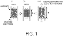
- FIG. 1 schematically illustrates electrode deformation ratio as an indication of the effect of the present invention.
- the production method for a negative electrode for an all-solid-state battery comprises the steps of: (1) coating a carbonaceous material having a true density of from 1.30 g/cm 3 to 2.10 g/cm 3 determined by a butanol method with a solid electrolyte; and (2) pressure-molding the solid electrolyte-coated carbonaceous material.
- the carbonaceous material used in the production method of the present invention is not limited as long as the carbonaceous material is turbostratic carbon and has a true density of from 1.30 g/cm 3 to 2.10 g/cm 3 determined by a butanol method, but a preferred mode is non-graphitizable carbon having a true density of not less than 1.30 g/cm 3 and not greater than 1.70 g/cm 3 determined by a butanol method, and another preferred mode is an easily graphitizable carbon having a true density of greater than 1.70 g/cm 3 and not greater than 2.10 g/cm 3 determined by a butanol method.
- the carbon source of the non-graphitizable carbon or the easily graphitizable carbon is not limited as long as non-graphitizable carbon or easily graphitizable carbon can be produced, and examples include petroleum pitch, coal pitch, thermoplastic resins (for example, ketone resins, polyvinyl alcohol, polyethylene terephthalate, polyacetal, polyacrylonitrile, styrene/divinylbenzene copolymers, polyimide, polycarbonate, modified polyphenylene ether, polybutylene terephthalate, polyarylate, polysulfone, polyphenylene sulfide, polyimide resins, fluororesins, polyamideimide, or polyetheretherketone), and thermosetting resins (for example, epoxy resins, urethane resins, urea resins, diallylphthalate resins, polyester resins, polycarbonate resins, silicon resins, polyacetal resins, nylon resins, furan resins, or aldehyde resin
- the average surface spacing of the (002) surface of a carbonaceous material indicates a value that decreases as the crystal integrity increases.
- the spacing of an ideal graphite structure yields a value of 0.3354 nm, and the value tends to increase as the structure is disordered. Accordingly, the average surface spacing is effective as an index indicating the carbon structure.
- the average surface spacing of the (002) surface of the carbonaceous material used in the production method of the present invention is not limited but is preferably from 0.340 to 0.400 nm, more preferably not less than 0.350 nm and not greater than 0.400 nm, and particularly preferably not less than 0.355 nm and not greater than 0.400 nm.
- a carbonaceous material having an average surface spacing of less than 0.340 nm may have poor cycle characteristics.
- the crystallite thickness L c(002) in the c-axis direction of the carbonaceous material used in the production method of the present invention is preferably from 0.5 to 10.0 nm.
- the upper limit of L c(002) is preferably not greater than 8.0 nm and more preferably not greater than 5.0 nm.
- L c(002) exceeds 10.0 nm, the volume expansion and contraction accompanying lithium doping and de-doping may become large. As a result, the carbon structure may be ruined, and lithium doping and de-doping may be obstructed, which may lead to poor repetition characteristics.
- the specific surface area may be determined with an approximation formula derived from a BET formula based on nitrogen adsorption.
- the specific surface area of the carbonaceous material used in the negative electrode for an all-solid-state battery according to the present invention is not limited but is preferably from 0.5 to 50 m 2 /g.
- the upper limit of the BET specific surface area is preferably not greater than 45 m 2 /g, more preferably not greater than 40 m 2 /g, and even more preferably not greater than 35 m 2 /g.
- the lower limit of the BET specific surface area is preferably not less than 1 m 2 /g.
- the true density of a graphitic material having an ideal structure is 2.27 g/cm 3 , and the true density tends to decrease as the crystal structure becomes disordered. Accordingly, the true density can be used as an index expressing the carbon structure.
- the true density of the carbonaceous material used in the negative electrode for an all-solid-state battery according to the present invention is from 1.30 g/cm 3 to 2.10 g/cm 3 .
- the upper limit of the true density is preferably not greater than 2.05 g/cm 3 and more preferably not greater than 2.00 g/cm 3 .
- the lower limit of the true density is preferably not less than 1.31 g/cm 3 , more preferably not less than 1.32 g/cm 3 , and even more preferably not less than 1.33 g/cm 3 . Further, the lower limit of the true density may be not less than 1.40 g/cm 3 .
- a carbonaceous material having a true density exceeding 2.10 g/cm 3 has a small number of pores of a size capable of storing lithium, and the doping and de-doping capacity is also small. Thus, this is not preferable.
- increases in true density involve the selective orientation of the carbon hexagonal plane, so the carbonaceous material often undergoes expansion and contraction at the time of lithium doping and de-doping, which is not preferable.
- a carbon material having a true density of less than 1.30 g/cm 3 may have a large number of closed pores, and the doping and de-doping capacity may be reduced, which is not preferable.
- the electrode density decreases and thus causes a decrease in the volume energy density, which is not preferable.
- non-graphitizable carbon is a general term for non-graphitizable carbon which typically does not transform into a graphite structure even when heat-treated at an ultra-high temperature of approximately 3,000°C, but a carbonaceous material having a true density of not less than 1.30 g/cm 3 and not greater than 1.70 g/cm 3 is called a non-graphitizable carbon here.
- “easily graphitizable carbon” is a general term for non-graphitic carbon which typically transforms into a graphite structure when heat-treated at a high temperature of approximately 2,000°C, but a carbonaceous material having a true density of not less than 1.70 g/cm 3 and not greater than 2.10 g/cm 3 is called an easily graphitizable carbon here.
- the average particle size (D v50 ) of the carbonaceous material used in the production method of the present invention is preferably from 1 to 50 ⁇ m.
- the lower limit of the average particle size is preferably not less than 1 ⁇ m, more preferably not less than 1.5 ⁇ m and particularly preferably not less than 2.0 ⁇ m.
- the upper limit of the average particle size is preferably not greater than 40 ⁇ m and more preferably not greater than 35 ⁇ m.
- the carbonaceous material used in the negative electrode for an all-solid-state battery according to the present invention is not limited but is preferably a carbonaceous material in which the exothermic peak temperature T (°C) according to differential thermal analysis and the butanol true density ⁇ Bt (g/cm 3 ) satisfy the following formula (1): 300 ⁇ T ⁇ 100 ⁇ ⁇ Bt ⁇ 650
- An exothermic peak typically refers to a change in response to the size of a carbon hexagonal plane of the carbonaceous material and the three-dimensional order thereof.
- a peak tends to appear on the high-temperature side for a larger carbon hexagonal plane and a higher three-dimensional order. Since such a carbonaceous material has a high three-dimensional order, the true density ⁇ Bt measured with a butanol method is also high.
- a graphite material having a large carbon hexagonal plane and having an surface spacing of 0.3354 nm exhibits an exothermic peak temperature of nearly 800°C.
- Such a carbonaceous material tends to be susceptible to crystal expansion and contraction due to repeated lithium doping and de-doping, and the charge/discharge repetition performance is poor.
- a peak typically tends to appear on the low-temperature side for a smaller carbon hexagonal plane and a lower three-dimensional order.
- Such a carbonaceous material involves smaller crystal expansion and contraction due to repeated lithium doping and de-doping than graphite and exhibits high cycle durability.
- the exothermic peak appears excessively on the low temperature side, the amount of fine pores or the fine pore size becomes excessively large, and the specific surface area is high, which leads to increases in irreversible capacity and is therefore not preferable.
- the true density ⁇ Bt measured with a butanol method becomes excessively low, which is not preferable from the perspective of the volume energy density.
- the carbonaceous material of the present invention preferably has an exothermic peak temperature T and a true density ⁇ Bt measured with a butanol method satisfying the relationship 305 ⁇ T-100 ⁇ Bt ⁇ 650 and more preferably 310 ⁇ T-100 ⁇ Bt ⁇ 650.
- the lower limit of T-100 ⁇ Bt of the carbonaceous material of the present invention may be 430.
- the solid electrolyte material that can be used in the production method for a negative electrode for an all-solid-state battery according to the present invention is not limited to a material used in the field of lithium-ion secondary batteries, and a solid electrolyte material comprising an organic compound, an inorganic compound, or a mixture thereof may be used.
- the solid electrolyte material has ionic conductivity and insulating properties.
- a specific example is a polymer electrolyte (for example, a true polymer electrolyte), a sulfide solid electrolyte material, or an oxide solid electrolyte material, but a sulfide solid electrolyte material is preferable.
- true polymer electrolytes include polymers having ethylene oxide bonds, crosslinked products thereof, copolymers thereof, and polyacrylonitrile- and polyacrylonitrile-based polymers, examples of which include polyethylene oxide, polyethylene carbonate, and polypropylene carbonate.
- Examples of sulfide solid electrolyte materials include Li 2 S, Al 2 S 3 , SiS 2 , GeS 2 , P 2 S 3 , P 2 S 5 , AS 2 S 3 , Sb 2 S 3 , and mixtures and combinations thereof. That is, examples of sulfide solid electrolyte materials include Li 2 S-Al 2 S 3 materials, Li 2 S-SiS 2 materials, Li 2 S-GeS 2 materials, Li2S-P2S3 materials, Li 2 S-P 2 S 5 materials, Li 2 S-As 2 S 3 materials, Li 2 S-Sb 2 S 3 materials, and Li 2 S materials, and Li 2 S-P 2 S 5 materials are particularly preferable. Further, Li 3 PO 4 , halogens, or halogenated compounds may be added to these solid electrolyte materials and used as solid electrolyte materials.
- oxide solid electrolyte materials include oxide solid electrolyte materials having a perovskite-type, NASICON-type, or garnet-type structure, examples of which include La 0.51 LiTiO 2.94 , Li 1.3 Al 0.3 Ti 1.7 (PO 4 ) 3 , Li 7 La 3 Zr 2 O 12 , and the like.
- the shape of the solid electrolyte material is not limited as long as the material functions as an electrolyte.
- the average particle size of the solid electrolyte material is also not particularly limited but is preferably from 0.1 ⁇ m to 50 ⁇ m.
- the lithium ion conductivity of the solid electrolyte material is not limited as long as the effect of the present invention can be achieved, but the lithium ion conductivity is preferably not less than 1x10 -6 S/cm and more preferably not less than 1x10 -5 S/cm.
- the Li 2 S-P 2 S 5 material described above can also be produced from Li 2 S and P 2 S 5 or may be produced using Li 2 S, a simple substance phosphorus, and a simple substance sulfur.
- the Li 2 S that is used may be a substance that is produced and marketed industrially but may also be produced with the following methods. Specific examples include: a method of producing hydrous Li 2 S by reacting lithium hydroxide and hydrogen sulfide at 0 to 150°C in an aprotic organic solvent and then dehydrosulfurizing the reaction solution at 150 to 200°C (see Japanese Unexamined Patent Application Publication No.
- H7-330312A a method of producing Li 2 S directly by reacting lithium hydroxide and hydrogen sulfide at 150 to 200°C in an aprotic organic solvent (see Japanese Unexamined Patent Application Publication No. H7-330312A ); and a method of reacting lithium hydroxide and a gaseous sulfur source at a temperature of from 130 to 445°C (see Japanese Unexamined Patent Application Publication No. H9-283156A ).
- the aforementioned P 2 S 5 that is used may also be a substance that is produced and marketed industrially.
- a simple substance phosphorus and simple substance sulfur may also be used instead of P 2 S 5 .
- the simple substance phosphorus and simple substance sulfur that are used may also be substances that are produced and marketed industrially.
- a Li 2 S-P 2 S 5 material can be produced with a melt-quenching method or a mechanical milling method using the aforementioned P 2 S 5 and Li 2 S.
- An electrolyte material obtained with these methods is a sulfurized glass and is amorphized.
- a solid electrolyte can be produced by mixing P 2 S 5 and Li 2 S at a molar ratio of from 50:50 to 80:20, for example, and preferably from 60:40 to 75:25.
- melt-quenching a mixture prepared in a pellet form with a mortar is placed in a carbon-coated quartz tube and vacuum-sealed. The mixture is then reacted for 0.1 to 12 hours at 400°C to 1,000°C.
- An amorphous solid electrolyte can be obtained by charging the obtained reaction product into ice and rapidly cooling the reaction product.
- a reaction can be performed at room temperature.
- an amorphous solid electrolyte can be obtained by performing treatment using a planetary ball mill for 0.5 to 100 hours at a revolution speed of from several tens to several hundreds of revolutions per minute.
- the production method of the present invention includes a step of coating the carbonaceous material with a solid electrolyte.
- the volume ratio of the carbonaceous material and the solid electrolyte is not limited as long as the effect of the present invention can be achieved, but the volume ratio is from 20:80 to 99:1 and more preferably from 30:70 to 97:3.
- the amount of the solid electrolyte added to the carbonaceous material is not limited as long as the effect of the present invention can be achieved but is preferably from 400 vol.% to 1 vol.%, more preferably from 300 vol.% to 3 vol.%, even more preferably from 250 vol.% to 5 vol.%, and even more preferably from 200 vol.% to 10 vol.% with respect to the volume of the carbonaceous material.
- the method of coating uses a ball mill and the surface of the carbonaceous material is coated with the solid electrolyte by mixing, mixing and dispersing, or mixing, dispersing, and pulverizing the carbonaceous material and the solid electrolyte with a ball mill and the carbonaceous material and the solid electrolyte are preferably mixed and dispersed or mixed, dispersed, and pulverized.
- the revolution speed of the ball mill is from 200 to 1,000 rpm, for example, and is preferably from 300 to 800 rpm.
- the setting time of the ball mill or the bead mill is from 30 to 600 minutes, for example, and is preferably from 60 to 480 minutes.
- the production method of the present invention includes a step of pressure-molding the carbonaceous material coated with the solid electrolyte.
- a conventionally known method can be used for the pressure molding operation, and the pressure molding operation is not particularly limited.
- the pressure at the time of pressure molding is not particularly limited but may be from 0.5 to 600 MPa, for example, preferably from 1.0 to 600 MPa, and more preferably from 2.0 to 600 MPa.
- a negative electrode for an all-solid-state battery obtained with the production method of the present invention may contain negative electrode materials, conductivity agents, and/or binders other than the aforementioned carbonaceous material as long as the effect of the present invention can be achieved. Negative electrode materials, conductivity agents, and/or binders may be added in the production method of the present invention.
- the production method of the present invention by coating the carbonaceous material with the solid electrolyte in the coating step of step (1) described above, it is possible to obtain a negative electrode in which the repulsion of the carbonaceous material after pressure molding is suppressed, and the deformation ratio of the negative electrode is small.
- the reason that a negative electrode having a small negative electrode deformation ratio can be obtained with the production method of the present invention is not completely understood but may be as follows. However, the present invention is not limited to the following description.
- the carbonaceous material used in the present invention has high particle strength, so when a negative electrode is produced using the carbonaceous material and a solid electrolyte, there are contact points (forming bridges) between the particles of the carbonaceous material, and a reaction force is generated in the perpendicular direction at the time of pressure molding ( FIG 1(ii) ). When the pressure due to this pressurization is released, the groups of particles forming contact points release the pressure and attempt to form a stable structure.
- the material deforms in the opposite direction as the load direction, and the thickness of the electrode becomes large ( FIG 1(iii) ). Peeling then occurs between the carbonaceous material and the solid electrolyte, and gaps are formed, which may diminish the input/output properties.
- the carbonaceous material forms bridges within the electrode, which may cause the wraparound of the solid electrolyte into the gaps of the carbonaceous material particles to be poor.
- the carbonaceous material since the surface of the carbonaceous material is coated with the solid electrolyte, the carbonaceous material is unlikely to form bridges, which may facilitate the wraparound of the solid electrolyte into the particles gaps. As a result, the reaction force of the carbonaceous material after pressure molding is suppressed. In addition, the electrode deformation ratio may be improved since the solid electrolyte having a lower modulus of elasticity than the carbonaceous material reduces the reaction force.
- the negative electrode for an all-solid-state battery according to the present invention is obtained by the production method described above. That is, the negative electrode for an all-solid-state battery according to the present invention contains: a carbonaceous material having a true density of from 1.30 g/cm 3 to 2.10 g/cm 3 determined by a butanol method; and a solid electrolyte.
- the carbonaceous materials and solid electrolytes include the carbonaceous materials and solid electrolytes described in "[1] Production method for a negative electrode for an all-solid-state battery" above.
- the negative electrode for an all-solid-state battery according to the present invention involves little peeling between the carbonaceous material and the solid electrolyte. Therefore, there are no gaps within the carbonaceous material, and the input/output properties are enhanced.
- the all-solid-state battery of the present invention comprises the negative electrode for an all-solid-state battery described above. More specifically, the all-solid-state battery comprises a negative electrode active material layer, a positive electrode active material layer, and a solid electrolyte layer, and the negative electrode for an all-solid-state battery according to the present invention may be used as the negative electrode active material layer.
- the negative electrode active material layer comprises the negative electrode for an all-solid-state battery described above. That is, the negative electrode active material layer contains the carbonaceous material and the solid electrolyte material described above but may further contain a conductivity agent and/or a binder.
- the volume of the carbonaceous material in the negative electrode active material layer with respect to the total volume of the negative electrode active material layer is preferably from 20 vol.% to 80 vol.% and more preferably from 30 vol.% to 70 vol.%.
- the carbonaceous material when the carbonaceous material is coated with the solid electrolyte at a volume ratio of 99:1, it is preferable to form the negative electrode active material layer by adding the solid electrolyte and the like so that the volume of the carbonaceous material with respect to the total volume of the negative electrode active material layer is from 20 vol.% to 80 vol.%.
- the negative electrode active material layer may contain negative electrode materials other than the aforementioned carbonaceous material as long as the effect of the present invention can be achieved.
- Examples of conductivity agents include acetylene black, Ketjen black, carbon nanofibers, carbon nanotubes, and carbon fibers.
- the content of the conductivity agent is not limited but may be from 0.5 to 15 wt.%, for example.
- An example of a binder is a fluorine-containing binder such as PTFE or PVDF.
- the content of the binder is not limited but may be from 0.5 to 15 wt.%, for example.
- the thickness of the negative electrode active material layer is not limited but is within the range of from 0.1 ⁇ m to 1,000 ⁇ m, for example.
- the negative electrode active material layer ordinarily has a current collector. SUS, copper, nickel, or carbon, for example, can be used as a negative electrode current collector, but of these, Cu or SUS is preferable.
- the positive electrode active material layer contains a positive electrode active material and a solid electrolyte material and may further contain a conductivity agent and/or a binder.
- the mixing ratio of the positive electrode active material and the solid electrolyte in the positive electrode active material layer is not limited and may be determined appropriately as long as the effect of the present invention can be achieved.
- the positive electrode active material can be used without limiting the positive electrode active material used in the all-solid-state battery.
- layered oxide-based as represented by LiMO 2 , where M is a metal such as LiCoO 2 , LiNiO 2 , LiMnO 2 , or LiNi x Co y Mn z O 2 (where x, y, and z represent composition ratios)
- olivine-based as represented by LiMPO 4 , where M is a metal such as LiFePO 4
- spinel-based as represented by LiM 2 O 4 , where M is a metal such as LiMn 2 O 4
- these chalcogen compounds may be mixed as necessary.
- the positive electrode active material layer may further contain a conductivity agent and/or a binder.
- conductivity agents include acetylene black, Ketjen black, and carbon fibers.
- the content of the conductivity agent is not limited but may be from 0.5 to 15 wt.%, for example.
- An example of a binder is a fluorine-containing binder such as PTFE or PVDF.
- the content of the conductivity agent is not limited but may be from 0.5 to 15 wt.%, for example.
- the thickness of the positive electrode active material layer is not limited but is within the range of from 0.1 ⁇ m to 1,000 ⁇ m, for example.
- the preparation method for the positive electrode active material layer is not particularly limited, but the positive electrode active material layer can be produced by mixing the positive electrode active material, the solid electrolyte material, and a conductivity agent and/or a binder as necessary and then pressure-molding the mixture.
- the positive electrode active material layer can also be produced by mixing the positive electrode active material, the solid electrolyte material, and a conductivity agent and/or a binder as necessary into a specific solvent to form a slurry and applying, drying, and then pressure-molding the mixture.
- the positive electrode active material layer ordinarily has a current collector. SUS, aluminum, nickel, iron, titanium, and carbon, for example, can be used as a positive electrode current collector, and of these, aluminum or SUS is preferable.
- the solid electrolyte layer contains the solid electrolyte described in the section "[1] Production method for a negative electrode for an all-solid-state battery" above.
- the content of the solid electrolyte with respect to the solid electrolyte layer is not particularly limited but may be from 10 vol.% to 100 vol.%, for example, and is preferably from 50 vol.% to 100 vol.%.
- the thickness of the solid electrolyte layer is also not particularly limited but may be from 0.1 ⁇ m to 1,000 ⁇ m, for example, and is preferably from 0.1 ⁇ m to 300 ⁇ m.
- the preparation method for the solid electrolyte layer is not particularly limited, but the solid electrolyte layer can be produced by a gas phase method or a pressure molding method.
- the gas phase method is not limited, but a vacuum deposition method, a pulse laser deposition method, a laser abrasion method, an ion plating method, or a sputtering method may be used.
- the solid electrolyte layer can be produced by mixing the solid electrolyte and a conductivity agent and/or a binder as necessary and pressure-molding the mixture.
- the solid electrolyte material layer can also be produced by mixing the solid electrolyte material and a conductivity agent and/or a binder as necessary into a specific solvent to form a slurry and applying, drying, and then pressure-molding the mixture.
- the production method of the all-solid-state battery is not particularly limited, and a known production method for an all-solid-state battery may be used.
- an all-solid-state battery can be obtained by pressure-molding a mixture prepared by mixing the material constituting the negative electrode for an all-solid-state battery according to the present invention as a negative electrode active material layer, the material constituting the positive electrode active material layer, and the material constituting the solid electrolyte layer.
- the order of pressure molding is not particularly limited, but examples include an order of the negative electrode active material layer, the solid electrolyte layer, and then the positive electrode active material layer, an order of the positive electrode active material layer, the solid electrolyte layer, and then the negative electrode active material layer, an order of the solid electrolyte layer, the negative electrode active material layer, and then the positive electrode active material layer, and an order of the solid electrolyte layer, the positive electrode active material layer, and then the negative electrode active material layer.
- Each layer of the solid electrolyte layer may also be compression-molded after being formed by the gas phase method described below.
- the measurement methods for the physical properties of the carbonaceous material for a nonaqueous electrolyte secondary battery according to the present invention (the "average surface spacing d (002) of the (002) surface and crystallite thickness L c(002) in the c-axis direction according to an X-ray diffraction method", the “specific surface area”, the “true density determined by a butanol method”, the “average particle size according to a laser diffraction method”, and “differential thermal analysis”) will be described hereinafter, but the physical properties described in this specification, including those in the working examples, are based on values determined by the following methods.
- the correction of the diffraction pattern was not performed for the Lorentz polarization factor, absorption factor, or atomic scattering factor, and the diffraction angle was corrected using the diffraction line of the (111) surface of a high-purity silicon powder serving as a standard substance.
- K the shape factor
- the specific surface area was measured in accordance with the method prescribed in JIS Z8830. A summary is given below.
- v m is the amount of adsorption (cm 3 /g) required to form a monomolecular layer on the sample surface; v is the amount of adsorption (cm 3 /g) actually measured, and x is the relative pressure).
- the amount of adsorption of nitrogen in the carbonaceous substance at the temperature of liquid nitrogen was measured as follows using a "Flow Sorb II2300" manufactured by MICROMERITICS.
- test tube was filled with the carbon material, and the test tube was cooled to -196°C while infusing helium gas containing nitrogen gas at a concentration of 20 mol% so that the nitrogen was adsorbed in the carbon material. Next, the test tube was returned to room temperature. The amount of nitrogen desorbed from the sample at this time was measured with a thermal conductivity detector and used as the adsorption gas amount v.
- the mass (m 1 ) of a pycnometer with a bypass line having an internal volume of approximately 40 mL was precisely measured.
- the mass (m 2 ) was precisely measured.
- 1-butanol was slowly added to the pycnometer to a depth of approximately 20 mm from the bottom.
- the pycnometer was gently oscillated, and after it was confirmed that no large air bubbles were formed, the pycnometer was placed in a vacuum desiccator and gradually evacuated to a pressure of 2.0 to 2.7 kPa.
- the pressure was maintained for 20 minutes or longer, and after the generation of air bubbles stopped, the bottle was removed and further filled with 1-butanol. After a stopper was inserted, the bottle was immersed in a constant-temperature bath (adjusted to 30 ⁇ 0.03°C) for at least 15 minutes, and the liquid surface of 1-butanol was aligned with the marked line. Next, the pycnometer was removed, and after the outside of the pycnometer was thoroughly wiped and the pycnometer was cooled to room temperature, the mass (m 4 ) was precisely measured. Next, the same pycnometer was filled with 1-butanol alone and immersed in a constant-temperature water bath in the same manner as described above.
- a dispersant cationic surfactant "SN-WET 366" (manufactured by the San Nopco Co.)
- SN-WET 366 cationic surfactant
- 30 mL of purified water was added, and after the sample was dispersed for approximately 2 minutes with an ultrasonic washer, the particle size distribution within the particle size range of 0.05 to 3,000 ⁇ m was determined with a particle size distribution measurement device ("SALD-3000J" manufactured by the Shimadzu Corporation).
- the average particle size D v50 ( ⁇ m) was determined from the resulting particle size distribution as the particle size yielding a cumulative volume of 50%.
- Differential thermal analysis was performed under a dry air flow using a DTG-60H manufactured by the Shimadzu Corporation.
- the analysis conditions were such that a 2 mg sample was analyzed under a 100 mL/min air flow at a heating rate of 10°C/min.
- the exothermic peak temperature was read from the differential thermal curve.
- this string-shaped compact was pulverized so that the ratio (L/D) of the diameter (D) and the length (L) was approximately 1.5 to 2.0, and the resulting pulverized product was added to an aqueous solution in which 0.53 mass% of polyvinyl alcohol (degree of saponification: 88%) heated to 93°C is dissolved, dispersed while stirring, and cooled to obtain a spherical pitch compact slurry. After most of the water was removed by filtration, the naphthalene in the pitch compact was extracted with n-hexane with a weight approximately six times that of the spherical pitch compact and removed.
- the porous spherical pitch obtained in this manner was heated to 260°C and held for one hour at 260°C while hot air was passed through to oxidize, thereby producing heat-infusible porous spherical oxidized pitch.
- the physical properties of the obtained carbonaceous material 1 included a specific surface area of 2.9 m 2 /g, an average particle size of 21.0 ⁇ m, a d (002) of 0.386 nm, a L c(002) of 1.1 nm, a ⁇ Bt of 1.52 g/cm 3 , an exothermic peak temperature T of 654°C, and a T-100 ⁇ Bt of 502.
- the resin was subjected to pre-calcination for one hour at 600°C in a nitrogen atmosphere (atmospheric pressure) and further heat-treated for one hour at 1,200°C in an argon gas atmosphere (atmospheric pressure) to obtain a carbonaceous material.
- the obtained carbonaceous material was further pulverized to obtain a carbonaceous material 2.
- the physical properties of the obtained carbonaceous material 2 included a specific surface area of 0.3 m 2 /g, an average particle size of 22.8 ⁇ m, a d (002) of 0.393 nm, a L c(002) of 1.1 nm, a ⁇ Bt of 1.41 g/cm 3 , an exothermic peak temperature T of 639°C, and a T-100 ⁇ Bt of 498.
- a carbonaceous material 3 was obtained by repeating the operations of Production Example 1 with the exception that in the oxidation of the porous spherical pitch, the temperature of the heating air was set to 165°C and held for one hour.
- the physical properties of the obtained carbonaceous material 3 included a specific surface area of 3.9 m 2 /g, an average particle size of 19.5 ⁇ m, a d (002) of 0.357 nm, a L c(002) of 1.8 nm, a ⁇ Bt of 1.97 g/cm 3 , an exothermic peak temperature T of 748°C, and a T-100 ⁇ Bt of 551.
- a negative electrode for an all-solid-state battery was produced by coating the carbonaceous material 2 with polyethylene glycol using a sol-gel method as an alternative solid electrolyte.
- the carbonaceous material 2 and polyethylene glycol were measured so that the weight ratio was 90:10 and the volume ratio was 84:16.
- the measured polyethylene glycol was dissolved in a mixed solvent of 10 g of methanol and water.
- the carbonaceous material 2 was dispersed in the solvent, and methanol was removed using a rotary evaporator.
- the obtained powder was dried for eight hours at 60°C in a vacuum to obtain a negative electrode 1.
- the electrode deformation ratio and the physical properties of only the carbonaceous material 2 obtained by removing the coated product after coating treatment are shown in Table 1.
- a negative electrode 2 was obtained by repeating the operations of Working Example 1 with the exception that the amounts of the carbonaceous material 2 and the alternative solid electrolyte were set to a weight ratio of 70:30 and a volume ratio of 65:35.
- the electrode deformation ratio and the physical properties of only the carbonaceous material 2 obtained by removing the coated product after coating treatment are shown in Table 1.
- a negative electrode 3 was obtained by repeating the operations of Working Example 1 with the exception that potassium bromide (KBr) was used as an alternative solid electrolyte, that the carbonaceous material 1 obtained in Production Example 1 was used as a carbonaceous material, and that the amounts of the carbonaceous material 1 and the alternative solid electrolyte were set to a weight ratio of 50:50 and a volume ratio of 65:35.
- the electrode deformation ratio and the physical properties of only the carbonaceous material 1 obtained by removing the coated product after coating treatment are shown in Table 2.
- a negative electrode for an all-solid-state battery was produced by mixing KBr as an alternative solid electrolyte into the carbonaceous material 1 obtained in Production Example 1 using a ball mill.
- the carbonaceous material 1 and KBr were measured so that the weight ratio was 50:50 and the volume ratio was 65:35.
- 4 mL of zirconia balls with a diameter of 2 mm were charged into a zirconia pot with a volume of 12 mL.
- the measured powder was placed in the container and mixed for one hour at a revolution speed of 600 rpm using a ball mill (P-6 manufactured by FRITSCH) to obtain a negative electrode 4.
- the electrode deformation ratio and the physical properties of only the carbonaceous material 1 obtained by removing the coated product after coating treatment are shown in Table 2.
- a negative electrode 5 was obtained by repeating the operations of Working Example 4 with the exception that the mixing time with the ball mill was set to three hours.
- the electrode deformation ratio and the physical properties of only the carbonaceous material 1 obtained by removing the coated product after coating treatment are shown in Table 2.
- a negative electrode 6 was obtained by repeating the operations of Working Example 4 with the exception that the mixing time with the ball mill was set to five hours.
- the electrode deformation ratio and the physical properties of only the carbonaceous material 1 obtained by removing the coated product after coating treatment are shown in Table 2.
- a negative electrode 7 was obtained by repeating the operations of Working Example 4 with the exception that the carbonaceous material 3 obtained in Production Example 3 was used.
- the electrode deformation ratio and the physical properties of only the carbonaceous material 3 obtained by removing the coated product after coating treatment are shown in Table 3.
- a negative electrode for an all-solid-state battery was produced by mixing polyethylene glycol as an alternative solid electrolyte into the carbonaceous material 2 obtained in Production Example 2 using a ball mill.
- the carbonaceous material 2 and polyethylene glycol were measured so that the weight ratio was 90:10 and the volume ratio was 84:16.
- 4 mL of zirconia balls with a diameter of 2 mm were charged into a zirconia pot with a volume of 12 mL.
- the measured powder was placed in the container and mixed for 20 minutes at a revolution speed of 150 rpm using a ball mill (P-6 manufactured by FRITSCH) to obtain a comparative negative electrode 1.
- the electrode deformation ratio and the physical properties of only the carbonaceous material 2 obtained after treatment are shown in Table 1.
- a comparative negative electrode 2 was obtained by repeating the operations of
- Comparative Example 1 Comparative Example 1 with the exception that the amounts of the carbonaceous material 2 and the alternative solid electrolyte were set to a weight ratio of 70:30 and a volume ratio of 65:35.
- the electrode deformation ratio and the physical properties of only the carbonaceous material 2 obtained after treatment are shown in Table 1.
- a comparative negative electrode 3 was obtained by repeating the operations of Comparative Example 1 with the exception that potassium bromide (KBr) was used as an alternative solid electrolyte, that the carbonaceous material 1 obtained in Production Example 1 was used as a carbonaceous material, and that the amounts of the carbonaceous material 1 and the alternative solid electrolyte were set to a weight ratio of 50:50 and a volume ratio of 65:35.
- the electrode deformation ratio and the physical properties of only the carbonaceous material 1 obtained after treatment are shown in Table 2.
- a comparative negative electrode 4 was obtained by repeating the operations of Comparative Example 1 with the exception that the carbonaceous material 3 obtained in Production Example 3 was used, that potassium bromide (KBr) was used as an alternative solid electrolyte, and that the amounts of the carbonaceous material 3 and the alternative solid electrolyte were set to a weight ratio of 50:50 and a volume ratio of 65:35.
- the electrode deformation ratio and the physical properties of only the carbonaceous material 3 obtained after treatment are shown in Table 3.
- Electrode deformation ratio B / A ⁇ 100 ⁇ 100 Table 1 Alternative solid electrolyte Weight ratio Volume ratio Specific surface area D v50 d (002) L c(002) ⁇ Bt Exothermic peak temperature T T-100 ⁇ Bt Mixed electrode Carbonaceous material 2 Alternative solid electrolyte Carbonaceous material 2 Alternative solid electrolyte Carbonaceous material 2 after treatment Carbonaceous material 2 after treatment Carbonaceous material 2 after treatment Carbonaceous material 2 after treatment Carbonaceous material 2 after treatment Carbonaceous material 2 after treatment Carbonaceous material 2 after treatment Carbonaceous material 2 after treatment Carbonaceous material 2 after treatment Carbonaceous material 2 after treatment At 400 MPa Electrode height A At 0 MPa Electrode height B Electrode deformation ratio [(B/A) ⁇ 100]-100 wt% wt% vol% vol% m 2 /g ⁇ m nm nm g/cm 3 °C cm cm cm % Working Example 1 PEG 90 10 84 16 0.3 22.8 0.393 1.1 1.41 639 498
- the negative electrode for an all-solid-state battery and an all-solid-state battery containing the same according to the present invention can be suitably used in hybrid electric vehicles (HEVs), plug-in hybrid electric vehicles (PHEVs), and electric vehicles (EVs).
- HEVs hybrid electric vehicles
- PHEVs plug-in hybrid electric vehicles
- EVs electric vehicles
Landscapes
- Chemical & Material Sciences (AREA)
- General Chemical & Material Sciences (AREA)
- Chemical Kinetics & Catalysis (AREA)
- Electrochemistry (AREA)
- Engineering & Computer Science (AREA)
- Manufacturing & Machinery (AREA)
- Materials Engineering (AREA)
- Inorganic Chemistry (AREA)
- Composite Materials (AREA)
- Physics & Mathematics (AREA)
- Condensed Matter Physics & Semiconductors (AREA)
- General Physics & Mathematics (AREA)
- Battery Electrode And Active Subsutance (AREA)
- Secondary Cells (AREA)
Applications Claiming Priority (2)
| Application Number | Priority Date | Filing Date | Title |
|---|---|---|---|
| JP2014074107 | 2014-03-31 | ||
| PCT/JP2015/060075 WO2015152215A1 (ja) | 2014-03-31 | 2015-03-31 | 全固体電池用負極電極の製造方法及び全固体電池用負極電極 |
Publications (3)
| Publication Number | Publication Date |
|---|---|
| EP3128583A1 EP3128583A1 (en) | 2017-02-08 |
| EP3128583A4 EP3128583A4 (en) | 2017-02-08 |
| EP3128583B1 true EP3128583B1 (en) | 2019-03-13 |
Family
ID=54240536
Family Applications (1)
| Application Number | Title | Priority Date | Filing Date |
|---|---|---|---|
| EP15773141.5A Active EP3128583B1 (en) | 2014-03-31 | 2015-03-31 | Method for producing negative electrode for all-solid battery, and negative electrode for all-solid battery |
Country Status (7)
| Country | Link |
|---|---|
| US (1) | US9947927B2 (ja) |
| EP (1) | EP3128583B1 (ja) |
| JP (1) | JP6129407B2 (ja) |
| KR (1) | KR101758037B1 (ja) |
| CN (1) | CN106133954B (ja) |
| TW (1) | TWI594484B (ja) |
| WO (1) | WO2015152215A1 (ja) |
Families Citing this family (7)
| Publication number | Priority date | Publication date | Assignee | Title |
|---|---|---|---|---|
| JP6933250B2 (ja) * | 2017-03-28 | 2021-09-08 | 株式会社村田製作所 | 全固体電池、電子機器、電子カード、ウェアラブル機器および電動車両 |
| FR3083006A1 (fr) * | 2018-06-22 | 2019-12-27 | Institut Polytechnique De Grenoble | Electrolyte polymere solide, son procede de preparation et accumulateur/cellule electrochimique en comprenant |
| JP2022029465A (ja) * | 2018-12-05 | 2022-02-18 | 昭和電工株式会社 | 全固体リチウムイオン電池 |
| JP2022029464A (ja) * | 2018-12-05 | 2022-02-18 | 昭和電工株式会社 | 全固体リチウムイオン電池 |
| JPWO2022092055A1 (ja) * | 2020-11-02 | 2022-05-05 | ||
| KR102527861B1 (ko) | 2021-02-01 | 2023-05-02 | 이앤이(주) | 전고체 전지용 음극 및 이의 제조방법 |
| CN113363436B (zh) * | 2021-05-14 | 2022-02-18 | 宁波梅山保税港区锂泰企业管理合伙企业(有限合伙) | 一种高能量密度和高循环性能的锂离子电池 |
Citations (2)
| Publication number | Priority date | Publication date | Assignee | Title |
|---|---|---|---|---|
| US6884546B1 (en) * | 1999-09-20 | 2005-04-26 | Sony Corporation | Secondary battery |
| JP2013214421A (ja) * | 2012-04-02 | 2013-10-17 | National Institute Of Advanced Industrial & Technology | 炭素−固体電解質複合体およびその製造方法 |
Family Cites Families (15)
| Publication number | Priority date | Publication date | Assignee | Title |
|---|---|---|---|---|
| JP2949180B2 (ja) * | 1992-03-24 | 1999-09-13 | 工業技術院長 | リチウム二次電池用負極 |
| JP3653105B2 (ja) | 1993-02-25 | 2005-05-25 | 呉羽化学工業株式会社 | 二次電池電極用炭素質材料 |
| JP3502669B2 (ja) | 1994-08-23 | 2004-03-02 | 呉羽化学工業株式会社 | 二次電池電極用炭素質材料およびその製造法 |
| JP4187282B2 (ja) * | 1996-06-10 | 2008-11-26 | 日立マクセル株式会社 | リチウムイオン二次電池 |
| JP4187804B2 (ja) | 1997-04-03 | 2008-11-26 | ソニー株式会社 | 非水溶媒系二次電池の電極用炭素質材料及びその製造方法、並びに非水溶媒系二次電池 |
| TW200723579A (en) | 2005-09-09 | 2007-06-16 | Kureha Corp | Negative electrode material for nonaqueous electrolyte secondary battery, process for producing the same, negative electrode and nonaqueous electrolyte secondary battery |
| JP5233314B2 (ja) | 2008-02-25 | 2013-07-10 | 住友ベークライト株式会社 | 二次電池用炭素材、二次電池用電極、および二次電池 |
| JP2009283344A (ja) * | 2008-05-23 | 2009-12-03 | Idemitsu Kosan Co Ltd | リチウム電池用負極合材、リチウム電池用負極、リチウム電池、装置およびリチウム電池用負極合材の製造方法 |
| WO2011086689A1 (ja) * | 2010-01-15 | 2011-07-21 | トヨタ自動車株式会社 | 電池用電極、当該電池用電極を備えた電池、及び、当該電池用電極の製造方法 |
| JP5682318B2 (ja) | 2011-01-12 | 2015-03-11 | トヨタ自動車株式会社 | 全固体電池 |
| JP5376412B2 (ja) * | 2011-01-19 | 2013-12-25 | 住友電気工業株式会社 | 非水電解質電池 |
| JP5858289B2 (ja) * | 2012-05-11 | 2016-02-10 | 株式会社豊田自動織機 | 二次電池用負極活物質、その製造方法、二次電池用負極、二次電池、及びSi−酸化物固体電解質複合体 |
| JP6243103B2 (ja) * | 2012-06-29 | 2017-12-06 | 出光興産株式会社 | 正極合材 |
| JPWO2014038494A1 (ja) * | 2012-09-06 | 2016-08-08 | 株式会社クレハ | 非水電解質二次電池負極用材料 |
| WO2014038492A1 (ja) | 2012-09-06 | 2014-03-13 | 株式会社クレハ | 非水電解質二次電池負極用炭素質材料及びその製造方法、並びに前記炭素質材料を用いた負極および非水電解質二次電池 |
-
2015
- 2015-03-31 WO PCT/JP2015/060075 patent/WO2015152215A1/ja active Application Filing
- 2015-03-31 KR KR1020167026970A patent/KR101758037B1/ko active IP Right Grant
- 2015-03-31 EP EP15773141.5A patent/EP3128583B1/en active Active
- 2015-03-31 CN CN201580017408.2A patent/CN106133954B/zh active Active
- 2015-03-31 JP JP2016511918A patent/JP6129407B2/ja active Active
- 2015-03-31 TW TW104110548A patent/TWI594484B/zh not_active IP Right Cessation
- 2015-03-31 US US15/300,356 patent/US9947927B2/en active Active
Patent Citations (2)
| Publication number | Priority date | Publication date | Assignee | Title |
|---|---|---|---|---|
| US6884546B1 (en) * | 1999-09-20 | 2005-04-26 | Sony Corporation | Secondary battery |
| JP2013214421A (ja) * | 2012-04-02 | 2013-10-17 | National Institute Of Advanced Industrial & Technology | 炭素−固体電解質複合体およびその製造方法 |
Also Published As
| Publication number | Publication date |
|---|---|
| KR20160118376A (ko) | 2016-10-11 |
| JPWO2015152215A1 (ja) | 2017-04-13 |
| KR101758037B1 (ko) | 2017-07-13 |
| US20170141395A1 (en) | 2017-05-18 |
| JP6129407B2 (ja) | 2017-05-17 |
| WO2015152215A1 (ja) | 2015-10-08 |
| EP3128583A1 (en) | 2017-02-08 |
| US9947927B2 (en) | 2018-04-17 |
| TWI594484B (zh) | 2017-08-01 |
| CN106133954A (zh) | 2016-11-16 |
| EP3128583A4 (en) | 2017-02-08 |
| TW201603365A (zh) | 2016-01-16 |
| CN106133954B (zh) | 2018-06-19 |
Similar Documents
| Publication | Publication Date | Title |
|---|---|---|
| EP3128582B1 (en) | Negative electrode for all-solid battery and all-solid battery including same | |
| EP3128583B1 (en) | Method for producing negative electrode for all-solid battery, and negative electrode for all-solid battery | |
| EP3118916B1 (en) | Cathode active material with core-shell structure for lithium battery, cathode for lithium battery including the same, and lithium battery including the cathode | |
| EP3203551B1 (en) | Positive electrode active material and method for manufacturing same | |
| CN108336331B (zh) | 电极活性材料、包含该电极活性材料的锂二次电池和制备该电极活性材料的方法 | |
| EP3471177B1 (en) | Negative electrode active material and negative electrode including the same | |
| JP2014029863A (ja) | 電極活物質である遷移金属化合物と繊維状炭素材料とを含有する複合体及びその製造方法 | |
| KR20150063620A (ko) | 리튬 이차 전지용 음극 활물질, 이의 제조 방법 및 이를 포함하는 리튬 이차 전지 | |
| JP2022550820A (ja) | 球状化カーボン系負極活物質、その製造方法、それを含む負極、及びリチウム二次電池 | |
| KR20220089183A (ko) | 리튬 이차 전지용 양극 활물질, 이의 제조방법 및 이를 포함하는 리튬 이차 전지 | |
| EP3179541B1 (en) | Carbonaceous material for negative electrode of non-aqueous electrolyte secondary battery | |
| WO2016158823A1 (ja) | 電池電極用炭素質成形体、及びその製造方法 | |
| EP4287305A1 (en) | Negative electrode material for lithium-ion secondary battery, evaluation method therefor, manufacturing method therefor, negative electrode for lithium-ion secondary battery, and lithium-ion secondary battery | |
| KR102342216B1 (ko) | 부극층 및 전고체 전지 | |
| CN114477310A (zh) | 正极活性物质的制造方法、正极活性物质和锂离子电池的制造方法 | |
| WO1998034291A1 (fr) | Accumulateur secondaire a ions lithium | |
| JP2016181348A (ja) | 非水電解質二次電池負極用炭素質材料及び非水電解質二次電池負極用炭素質材料の製造方法 | |
| CN112640162A (zh) | 用于可再充电锂电池的正极活性物质、其制造方法以及包括其的可再充电锂电池 | |
| EP4394926A1 (en) | Negative electrode active material, method for preparing same, and lithium secondary battery comprising same | |
| TW202408926A (zh) | 非石墨化性碳、混合碳粉、鋰離子二次電池用負極、鋰離子二次電池 | |
| JP2024524173A (ja) | 負極活物質、その製造方法およびこれを含むリチウム二次電池 |
Legal Events
| Date | Code | Title | Description |
|---|---|---|---|
| STAA | Information on the status of an ep patent application or granted ep patent |
Free format text: STATUS: THE INTERNATIONAL PUBLICATION HAS BEEN MADE |
|
| PUAI | Public reference made under article 153(3) epc to a published international application that has entered the european phase |
Free format text: ORIGINAL CODE: 0009012 |
|
| STAA | Information on the status of an ep patent application or granted ep patent |
Free format text: STATUS: REQUEST FOR EXAMINATION WAS MADE |
|
| 17P | Request for examination filed |
Effective date: 20160930 |
|
| A4 | Supplementary search report drawn up and despatched |
Effective date: 20161208 |
|
| AK | Designated contracting states |
Kind code of ref document: A1 Designated state(s): AL AT BE BG CH CY CZ DE DK EE ES FI FR GB GR HR HU IE IS IT LI LT LU LV MC MK MT NL NO PL PT RO RS SE SI SK SM TR |
|
| AX | Request for extension of the european patent |
Extension state: BA ME |
|
| DAV | Request for validation of the european patent (deleted) | ||
| DAX | Request for extension of the european patent (deleted) | ||
| STAA | Information on the status of an ep patent application or granted ep patent |
Free format text: STATUS: EXAMINATION IS IN PROGRESS |
|
| 17Q | First examination report despatched |
Effective date: 20170926 |
|
| RIC1 | Information provided on ipc code assigned before grant |
Ipc: H01M 4/133 20100101ALI20180816BHEP Ipc: H01M 4/1393 20100101AFI20180816BHEP Ipc: H01M 4/62 20060101ALI20180816BHEP Ipc: H01M 4/02 20060101ALN20180816BHEP Ipc: H01M 4/587 20100101ALI20180816BHEP Ipc: H01M 4/04 20060101ALI20180816BHEP Ipc: H01M 10/0562 20100101ALI20180816BHEP Ipc: H01M 4/36 20060101ALI20180816BHEP Ipc: H01M 10/052 20100101ALN20180816BHEP |
|
| GRAP | Despatch of communication of intention to grant a patent |
Free format text: ORIGINAL CODE: EPIDOSNIGR1 |
|
| STAA | Information on the status of an ep patent application or granted ep patent |
Free format text: STATUS: GRANT OF PATENT IS INTENDED |
|
| INTG | Intention to grant announced |
Effective date: 20180926 |
|
| GRAS | Grant fee paid |
Free format text: ORIGINAL CODE: EPIDOSNIGR3 |
|
| GRAA | (expected) grant |
Free format text: ORIGINAL CODE: 0009210 |
|
| STAA | Information on the status of an ep patent application or granted ep patent |
Free format text: STATUS: THE PATENT HAS BEEN GRANTED |
|
| AK | Designated contracting states |
Kind code of ref document: B1 Designated state(s): AL AT BE BG CH CY CZ DE DK EE ES FI FR GB GR HR HU IE IS IT LI LT LU LV MC MK MT NL NO PL PT RO RS SE SI SK SM TR |
|
| REG | Reference to a national code |
Ref country code: GB Ref legal event code: FG4D |
|
| REG | Reference to a national code |
Ref country code: CH Ref legal event code: EP Ref country code: AT Ref legal event code: REF Ref document number: 1108924 Country of ref document: AT Kind code of ref document: T Effective date: 20190315 |
|
| REG | Reference to a national code |
Ref country code: IE Ref legal event code: FG4D |
|
| REG | Reference to a national code |
Ref country code: DE Ref legal event code: R096 Ref document number: 602015026434 Country of ref document: DE |
|
| REG | Reference to a national code |
Ref country code: NL Ref legal event code: MP Effective date: 20190313 |
|
| REG | Reference to a national code |
Ref country code: LT Ref legal event code: MG4D |
|
| PG25 | Lapsed in a contracting state [announced via postgrant information from national office to epo] |
Ref country code: FI Free format text: LAPSE BECAUSE OF FAILURE TO SUBMIT A TRANSLATION OF THE DESCRIPTION OR TO PAY THE FEE WITHIN THE PRESCRIBED TIME-LIMIT Effective date: 20190313 Ref country code: SE Free format text: LAPSE BECAUSE OF FAILURE TO SUBMIT A TRANSLATION OF THE DESCRIPTION OR TO PAY THE FEE WITHIN THE PRESCRIBED TIME-LIMIT Effective date: 20190313 Ref country code: LT Free format text: LAPSE BECAUSE OF FAILURE TO SUBMIT A TRANSLATION OF THE DESCRIPTION OR TO PAY THE FEE WITHIN THE PRESCRIBED TIME-LIMIT Effective date: 20190313 Ref country code: NO Free format text: LAPSE BECAUSE OF FAILURE TO SUBMIT A TRANSLATION OF THE DESCRIPTION OR TO PAY THE FEE WITHIN THE PRESCRIBED TIME-LIMIT Effective date: 20190613 |
|
| PG25 | Lapsed in a contracting state [announced via postgrant information from national office to epo] |
Ref country code: NL Free format text: LAPSE BECAUSE OF FAILURE TO SUBMIT A TRANSLATION OF THE DESCRIPTION OR TO PAY THE FEE WITHIN THE PRESCRIBED TIME-LIMIT Effective date: 20190313 Ref country code: RS Free format text: LAPSE BECAUSE OF FAILURE TO SUBMIT A TRANSLATION OF THE DESCRIPTION OR TO PAY THE FEE WITHIN THE PRESCRIBED TIME-LIMIT Effective date: 20190313 Ref country code: HR Free format text: LAPSE BECAUSE OF FAILURE TO SUBMIT A TRANSLATION OF THE DESCRIPTION OR TO PAY THE FEE WITHIN THE PRESCRIBED TIME-LIMIT Effective date: 20190313 Ref country code: GR Free format text: LAPSE BECAUSE OF FAILURE TO SUBMIT A TRANSLATION OF THE DESCRIPTION OR TO PAY THE FEE WITHIN THE PRESCRIBED TIME-LIMIT Effective date: 20190614 Ref country code: LV Free format text: LAPSE BECAUSE OF FAILURE TO SUBMIT A TRANSLATION OF THE DESCRIPTION OR TO PAY THE FEE WITHIN THE PRESCRIBED TIME-LIMIT Effective date: 20190313 Ref country code: BG Free format text: LAPSE BECAUSE OF FAILURE TO SUBMIT A TRANSLATION OF THE DESCRIPTION OR TO PAY THE FEE WITHIN THE PRESCRIBED TIME-LIMIT Effective date: 20190613 |
|
| REG | Reference to a national code |
Ref country code: AT Ref legal event code: MK05 Ref document number: 1108924 Country of ref document: AT Kind code of ref document: T Effective date: 20190313 |
|
| PG25 | Lapsed in a contracting state [announced via postgrant information from national office to epo] |
Ref country code: EE Free format text: LAPSE BECAUSE OF FAILURE TO SUBMIT A TRANSLATION OF THE DESCRIPTION OR TO PAY THE FEE WITHIN THE PRESCRIBED TIME-LIMIT Effective date: 20190313 Ref country code: ES Free format text: LAPSE BECAUSE OF FAILURE TO SUBMIT A TRANSLATION OF THE DESCRIPTION OR TO PAY THE FEE WITHIN THE PRESCRIBED TIME-LIMIT Effective date: 20190313 Ref country code: CZ Free format text: LAPSE BECAUSE OF FAILURE TO SUBMIT A TRANSLATION OF THE DESCRIPTION OR TO PAY THE FEE WITHIN THE PRESCRIBED TIME-LIMIT Effective date: 20190313 Ref country code: IT Free format text: LAPSE BECAUSE OF FAILURE TO SUBMIT A TRANSLATION OF THE DESCRIPTION OR TO PAY THE FEE WITHIN THE PRESCRIBED TIME-LIMIT Effective date: 20190313 Ref country code: RO Free format text: LAPSE BECAUSE OF FAILURE TO SUBMIT A TRANSLATION OF THE DESCRIPTION OR TO PAY THE FEE WITHIN THE PRESCRIBED TIME-LIMIT Effective date: 20190313 Ref country code: PT Free format text: LAPSE BECAUSE OF FAILURE TO SUBMIT A TRANSLATION OF THE DESCRIPTION OR TO PAY THE FEE WITHIN THE PRESCRIBED TIME-LIMIT Effective date: 20190713 Ref country code: SK Free format text: LAPSE BECAUSE OF FAILURE TO SUBMIT A TRANSLATION OF THE DESCRIPTION OR TO PAY THE FEE WITHIN THE PRESCRIBED TIME-LIMIT Effective date: 20190313 Ref country code: AL Free format text: LAPSE BECAUSE OF FAILURE TO SUBMIT A TRANSLATION OF THE DESCRIPTION OR TO PAY THE FEE WITHIN THE PRESCRIBED TIME-LIMIT Effective date: 20190313 |
|
| REG | Reference to a national code |
Ref country code: CH Ref legal event code: PL |
|
| PG25 | Lapsed in a contracting state [announced via postgrant information from national office to epo] |
Ref country code: PL Free format text: LAPSE BECAUSE OF FAILURE TO SUBMIT A TRANSLATION OF THE DESCRIPTION OR TO PAY THE FEE WITHIN THE PRESCRIBED TIME-LIMIT Effective date: 20190313 Ref country code: LU Free format text: LAPSE BECAUSE OF NON-PAYMENT OF DUE FEES Effective date: 20190331 Ref country code: SM Free format text: LAPSE BECAUSE OF FAILURE TO SUBMIT A TRANSLATION OF THE DESCRIPTION OR TO PAY THE FEE WITHIN THE PRESCRIBED TIME-LIMIT Effective date: 20190313 |
|
| REG | Reference to a national code |
Ref country code: BE Ref legal event code: MM Effective date: 20190331 |
|
| REG | Reference to a national code |
Ref country code: DE Ref legal event code: R097 Ref document number: 602015026434 Country of ref document: DE |
|
| PG25 | Lapsed in a contracting state [announced via postgrant information from national office to epo] |
Ref country code: AT Free format text: LAPSE BECAUSE OF FAILURE TO SUBMIT A TRANSLATION OF THE DESCRIPTION OR TO PAY THE FEE WITHIN THE PRESCRIBED TIME-LIMIT Effective date: 20190313 Ref country code: IS Free format text: LAPSE BECAUSE OF FAILURE TO SUBMIT A TRANSLATION OF THE DESCRIPTION OR TO PAY THE FEE WITHIN THE PRESCRIBED TIME-LIMIT Effective date: 20190713 |
|
| PLBE | No opposition filed within time limit |
Free format text: ORIGINAL CODE: 0009261 |
|
| STAA | Information on the status of an ep patent application or granted ep patent |
Free format text: STATUS: NO OPPOSITION FILED WITHIN TIME LIMIT |
|
| PG25 | Lapsed in a contracting state [announced via postgrant information from national office to epo] |
Ref country code: DK Free format text: LAPSE BECAUSE OF FAILURE TO SUBMIT A TRANSLATION OF THE DESCRIPTION OR TO PAY THE FEE WITHIN THE PRESCRIBED TIME-LIMIT Effective date: 20190313 Ref country code: MC Free format text: LAPSE BECAUSE OF FAILURE TO SUBMIT A TRANSLATION OF THE DESCRIPTION OR TO PAY THE FEE WITHIN THE PRESCRIBED TIME-LIMIT Effective date: 20190313 Ref country code: LI Free format text: LAPSE BECAUSE OF NON-PAYMENT OF DUE FEES Effective date: 20190331 Ref country code: CH Free format text: LAPSE BECAUSE OF NON-PAYMENT OF DUE FEES Effective date: 20190331 Ref country code: IE Free format text: LAPSE BECAUSE OF NON-PAYMENT OF DUE FEES Effective date: 20190331 |
|
| 26N | No opposition filed |
Effective date: 20191216 |
|
| PG25 | Lapsed in a contracting state [announced via postgrant information from national office to epo] |
Ref country code: BE Free format text: LAPSE BECAUSE OF NON-PAYMENT OF DUE FEES Effective date: 20190331 Ref country code: SI Free format text: LAPSE BECAUSE OF FAILURE TO SUBMIT A TRANSLATION OF THE DESCRIPTION OR TO PAY THE FEE WITHIN THE PRESCRIBED TIME-LIMIT Effective date: 20190313 |
|
| PG25 | Lapsed in a contracting state [announced via postgrant information from national office to epo] |
Ref country code: TR Free format text: LAPSE BECAUSE OF FAILURE TO SUBMIT A TRANSLATION OF THE DESCRIPTION OR TO PAY THE FEE WITHIN THE PRESCRIBED TIME-LIMIT Effective date: 20190313 |
|
| PG25 | Lapsed in a contracting state [announced via postgrant information from national office to epo] |
Ref country code: MT Free format text: LAPSE BECAUSE OF NON-PAYMENT OF DUE FEES Effective date: 20190331 |
|
| PG25 | Lapsed in a contracting state [announced via postgrant information from national office to epo] |
Ref country code: CY Free format text: LAPSE BECAUSE OF FAILURE TO SUBMIT A TRANSLATION OF THE DESCRIPTION OR TO PAY THE FEE WITHIN THE PRESCRIBED TIME-LIMIT Effective date: 20190313 |
|
| PG25 | Lapsed in a contracting state [announced via postgrant information from national office to epo] |
Ref country code: HU Free format text: LAPSE BECAUSE OF FAILURE TO SUBMIT A TRANSLATION OF THE DESCRIPTION OR TO PAY THE FEE WITHIN THE PRESCRIBED TIME-LIMIT; INVALID AB INITIO Effective date: 20150331 |
|
| PG25 | Lapsed in a contracting state [announced via postgrant information from national office to epo] |
Ref country code: MK Free format text: LAPSE BECAUSE OF FAILURE TO SUBMIT A TRANSLATION OF THE DESCRIPTION OR TO PAY THE FEE WITHIN THE PRESCRIBED TIME-LIMIT Effective date: 20190313 |
|
| PGFP | Annual fee paid to national office [announced via postgrant information from national office to epo] |
Ref country code: FR Payment date: 20230324 Year of fee payment: 9 |
|
| PGFP | Annual fee paid to national office [announced via postgrant information from national office to epo] |
Ref country code: GB Payment date: 20230322 Year of fee payment: 9 Ref country code: DE Payment date: 20220620 Year of fee payment: 9 |