EP3124699B1 - Strukturobjekt für strassen und strassenstruktur damit - Google Patents
Strukturobjekt für strassen und strassenstruktur damit Download PDFInfo
- Publication number
- EP3124699B1 EP3124699B1 EP16176892.4A EP16176892A EP3124699B1 EP 3124699 B1 EP3124699 B1 EP 3124699B1 EP 16176892 A EP16176892 A EP 16176892A EP 3124699 B1 EP3124699 B1 EP 3124699B1
- Authority
- EP
- European Patent Office
- Prior art keywords
- lane
- traveling direction
- inbound
- wind
- outbound
- Prior art date
- Legal status (The legal status is an assumption and is not a legal conclusion. Google has not performed a legal analysis and makes no representation as to the accuracy of the status listed.)
- Not-in-force
Links
- 238000007664 blowing Methods 0.000 claims description 26
- 230000008859 change Effects 0.000 claims description 14
- 239000000446 fuel Substances 0.000 description 28
- 238000012360 testing method Methods 0.000 description 9
- 230000004888 barrier function Effects 0.000 description 6
- 230000000694 effects Effects 0.000 description 6
- 238000005259 measurement Methods 0.000 description 6
- 230000001681 protective effect Effects 0.000 description 6
- 230000009467 reduction Effects 0.000 description 5
- 238000000034 method Methods 0.000 description 3
- 230000002829 reductive effect Effects 0.000 description 3
- 230000005611 electricity Effects 0.000 description 2
- 230000002401 inhibitory effect Effects 0.000 description 2
- 239000004809 Teflon Substances 0.000 description 1
- 229920006362 Teflon® Polymers 0.000 description 1
- NIXOWILDQLNWCW-UHFFFAOYSA-N acrylic acid group Chemical group C(C=C)(=O)O NIXOWILDQLNWCW-UHFFFAOYSA-N 0.000 description 1
- 230000015556 catabolic process Effects 0.000 description 1
- 238000006731 degradation reaction Methods 0.000 description 1
- 230000001419 dependent effect Effects 0.000 description 1
- 238000011161 development Methods 0.000 description 1
- 230000018109 developmental process Effects 0.000 description 1
- 230000000670 limiting effect Effects 0.000 description 1
- 238000004519 manufacturing process Methods 0.000 description 1
- 239000002184 metal Substances 0.000 description 1
- 238000012986 modification Methods 0.000 description 1
- 230000004048 modification Effects 0.000 description 1
- 229920003229 poly(methyl methacrylate) Polymers 0.000 description 1
- 239000004417 polycarbonate Substances 0.000 description 1
- 229920000515 polycarbonate Polymers 0.000 description 1
- 239000004926 polymethyl methacrylate Substances 0.000 description 1
- 239000011347 resin Substances 0.000 description 1
- 229920005989 resin Polymers 0.000 description 1
Images






Classifications
-
- E—FIXED CONSTRUCTIONS
- E01—CONSTRUCTION OF ROADS, RAILWAYS, OR BRIDGES
- E01F—ADDITIONAL WORK, SUCH AS EQUIPPING ROADS OR THE CONSTRUCTION OF PLATFORMS, HELICOPTER LANDING STAGES, SIGNS, SNOW FENCES, OR THE LIKE
- E01F15/00—Safety arrangements for slowing, redirecting or stopping errant vehicles, e.g. guard posts or bollards; Arrangements for reducing damage to roadside structures due to vehicular impact
- E01F15/02—Continuous barriers extending along roads or between traffic lanes
- E01F15/08—Continuous barriers extending along roads or between traffic lanes essentially made of walls or wall-like elements ; Cable-linked blocks
-
- E—FIXED CONSTRUCTIONS
- E01—CONSTRUCTION OF ROADS, RAILWAYS, OR BRIDGES
- E01F—ADDITIONAL WORK, SUCH AS EQUIPPING ROADS OR THE CONSTRUCTION OF PLATFORMS, HELICOPTER LANDING STAGES, SIGNS, SNOW FENCES, OR THE LIKE
- E01F7/00—Devices affording protection against snow, sand drifts, side-wind effects, snowslides, avalanches or falling rocks; Anti-dazzle arrangements ; Sight-screens for roads, e.g. to mask accident site
- E01F7/02—Snow fences or similar devices, e.g. devices affording protection against sand drifts or side-wind effects
- E01F7/025—Devices specially adapted for protecting against wind, e.g. screens, deflectors or attenuators at tunnel or lock entrances
-
- E—FIXED CONSTRUCTIONS
- E01—CONSTRUCTION OF ROADS, RAILWAYS, OR BRIDGES
- E01F—ADDITIONAL WORK, SUCH AS EQUIPPING ROADS OR THE CONSTRUCTION OF PLATFORMS, HELICOPTER LANDING STAGES, SIGNS, SNOW FENCES, OR THE LIKE
- E01F7/00—Devices affording protection against snow, sand drifts, side-wind effects, snowslides, avalanches or falling rocks; Anti-dazzle arrangements ; Sight-screens for roads, e.g. to mask accident site
- E01F7/02—Snow fences or similar devices, e.g. devices affording protection against sand drifts or side-wind effects
-
- E—FIXED CONSTRUCTIONS
- E01—CONSTRUCTION OF ROADS, RAILWAYS, OR BRIDGES
- E01F—ADDITIONAL WORK, SUCH AS EQUIPPING ROADS OR THE CONSTRUCTION OF PLATFORMS, HELICOPTER LANDING STAGES, SIGNS, SNOW FENCES, OR THE LIKE
- E01F7/00—Devices affording protection against snow, sand drifts, side-wind effects, snowslides, avalanches or falling rocks; Anti-dazzle arrangements ; Sight-screens for roads, e.g. to mask accident site
- E01F7/06—Anti-dazzle arrangements ; Securing anti-dazzle means to crash-barriers
-
- F—MECHANICAL ENGINEERING; LIGHTING; HEATING; WEAPONS; BLASTING
- F03—MACHINES OR ENGINES FOR LIQUIDS; WIND, SPRING, OR WEIGHT MOTORS; PRODUCING MECHANICAL POWER OR A REACTIVE PROPULSIVE THRUST, NOT OTHERWISE PROVIDED FOR
- F03D—WIND MOTORS
- F03D3/00—Wind motors with rotation axis substantially perpendicular to the air flow entering the rotor
- F03D3/005—Wind motors with rotation axis substantially perpendicular to the air flow entering the rotor the axis being vertical
-
- Y—GENERAL TAGGING OF NEW TECHNOLOGICAL DEVELOPMENTS; GENERAL TAGGING OF CROSS-SECTIONAL TECHNOLOGIES SPANNING OVER SEVERAL SECTIONS OF THE IPC; TECHNICAL SUBJECTS COVERED BY FORMER USPC CROSS-REFERENCE ART COLLECTIONS [XRACs] AND DIGESTS
- Y02—TECHNOLOGIES OR APPLICATIONS FOR MITIGATION OR ADAPTATION AGAINST CLIMATE CHANGE
- Y02E—REDUCTION OF GREENHOUSE GAS [GHG] EMISSIONS, RELATED TO ENERGY GENERATION, TRANSMISSION OR DISTRIBUTION
- Y02E10/00—Energy generation through renewable energy sources
- Y02E10/70—Wind energy
- Y02E10/74—Wind turbines with rotation axis perpendicular to the wind direction
Definitions
- the present invention relates to a structural object to be built on a road and a road structure having the same.
- Japanese Unexamined Patent Application Publication No. 2010-163850 discloses a windbreak wall that is built along a road.
- This windbreak has a plurality of louvers arranged along the road.
- the louvers are placed so that the side of each louver in the vehicle traveling direction is inclined inward and the site opposite to the vehicle traveling direction is inclined outward.
- wind blowing on a vehicle obliquely from the front and from the sides is suppressed
- wind blowing on the vehicle obliquely from the back and from the back passes through, thereby contributing to reduction of fuel consumption of the vehicle.
- An object of the present invention is to provide a technique to improve the fuel efficiency of another vehicle with utilization of wind generated by traveling of a vehicle.
- US 3 349 674 A discloses a structural object for road to be mounted between a first lane and a second lane being an opposite lane of the first lane.
- This structural object is made up of a combination of a plurality of flat surfaces.
- Each surface of the structural object consists of a combination of flat surfaces which are connected to each other in a projecting.
- This structure brings about a wind blowing from the first or second lane which causes a swirling flow at the boundary between two adjacent flat surfaces. This results in a loss of kinetic energy of the blowing from the first or second lane.
- the combination of a plurality of flat surfaces forms an interrupted angled surface, and does not lead to a total smooth surface.
- US 3 349 674 A intends such a shape of abrupt change of direction along the plurality of flat surfaces seen in the wind direction which is brought about by the intended Z-shape, leading to the respective flow resistance.
- US 5 181 695 A discloses another structural object for road to be mounted between a first lane and a second lane being an opposite lane of the first lane.
- This structural object has a first wall surface facing the same direction as a traveling direction of the first lane, and a second wall surface facing the same direction as a traveling direction of the second lane. Both the first wall surface and the second wall surface are flat surfaces and have right-angled end portions.
- An object of the present invention is to provide a technique to improve the fuel efficiency of another vehicle with utilization of wind generated by traveling of a vehicle.
- the first wall surface contains a flat surface and a curved surface in order from the second lane to the first lane
- the second wall surface contains a flat surface and a curved surface in order from the first lane to the second lane.
- the above-described structural object for the road has a first curved plate that is curved to be convex toward the traveling direction of the second lane in a plan view, a flat plate that is inclined toward the traveling direction of the first lane in the plan view as it goes from the first lane to the second lane, and a second curved plate that is curved to be convex toward the traveling direction of the first lane in the plan view, in order from the first lane to the second lane, and is formed to be substantially S shaped in the plan view, the first curved plate and the flat plate form the concave part of the first wall surface, and the flat plate and the second curved plate form the concave part of the second wall surface.
- first curved plate, the flat plate, and the second curved plate are formed integrally.
- the first curved plate, the flat plate, and the second curved plate are formed separately from one another, the first curved plate and the flat plate are arranged separately, the flat plate and the second curved plate are arranged separately, the first curved plate and the flat plate partly overlap in this order in the traveling direction of the first lane, and the flat plate and the second curved plate partly overlap in this order in the traveling direction of the first lane.
- the wind passes through a gap between the flat plate and the first curved plate, is guided by the first curved plate, and the momentum in the same direction as the traveling direction of the first lane is applied.
- a road structure includes the first lane, the second lane, and a plurality of the above-described structural objects for the road that are arranged between the first lane and the second lane at specified intervals along the first lane or the second lane.
- the road structure includes a median strip between the first lane and the second lane, and the plurality of structural objects for the road are mounted on the median strip.
- the road structure further includes a vertical axis wind generator placed between two adjacent ones of the plurality of structural objects for the road. In this structure, it is possible to efficiently generate electricity.
- the road structure further includes a side wall mounted on a side of the first lane opposite to the side of the first lane on which the second lane is located, and the side wall has a plurality of inclined surfaces arranged along the first lane, and each of the inclined surfaces is inclined toward the first lane as it goes to the traveling direction of the first lane in the plan view.
- wind that is generated by traveling of a leading vehicle and blows on the side wall is guided by the plurality of inclined surfaces and flows back into the first lane, maintaining the momentum in the traveling direction.
- the side wall has a depression between two adjacent ones of the inclined surfaces in the traveling direction of the first lane.
- wind that is generated by traveling of a leading vehicle and blows on the side wall becomes a spiral flow and is temporarily held in the depression and then flows back into the first lane.
- this structure even when there is a rather long distance between the leading vehicle and the following vehicle, it is possible to contribute to reduction of fuel consumption of the following vehicle.
- a road structure 1 according to a first embodiment is described hereinafter with reference to Figs. 1 to 9 .
- the road structure 1 contains an inbound lane 2 (first lane), an outbound lane 3 (second lane), a median strip 4, an inbound side wall 5 (side wall), an outbound side wall 6 (side wall), a plurality of blades 7 (structural objects for road), a protective barrier 40, and a wind generator 15.
- a track 8 (vehicle, subject vehicle) is traveling.
- the traveling direction of the inbound lane 2 is referred to as an inbound traveling direction 2A.
- the outbound lane 3 is the opposite lane of the inbound lane 2.
- a track 9 vehicle, oncoming vehicle
- the traveling direction of the outbound lane 3 is referred to as an outbound traveling direction 3A.
- the inbound lane 2 and the outbound lane 3 form a roadway 39.
- the median strip 4 is located between the inbound lane 2 and the outbound lane 3.
- the protective barrier 40 is placed in the median strip 4.
- the protective barrier 40 prevents the track 8 traveling in the inbound lane 2 from crossing the median strip 4 into the outbound lane 3 due to some reason and also prevents the track 9 traveling in the outbound lane 3 from crossing the median strip 4 into the inbound lane 2 due to some reason.
- the inbound side wall 5 is placed on a side of the inbound lane 2 opposite to the side of the inbound lane 2 on which the median strip 4 is located. In other words, the inbound side wall 5 is placed on a side of the inbound lane 2 opposite to the side of the inbound lane 2 on which the median the outbound lane 3 is located.
- the outbound side wall 6 is placed on a side of the outbound lane 3 opposite to the side of the outbound lane 3 on which the median strip 4 is located. In other words, the outbound side wall 6 is placed on a side of the outbound lane 3 opposite to the side of the outbound lane 3 on which the inbound lane 2 is located.
- the inbound side wall 5 and the outbound side wall 6 are placed with the roadway 39 located therebetween.
- the plurality of blades 7 are placed between the inbound lane 2 and the outbound lane 3. Specifically, the plurality of blades 7 are placed on the median strip 4. The plurality of blades 7 are arranged at specified intervals along the inbound lane 2 or the outbound lane 3. As shown in Fig. 1 , each blade 7 is fixed to the median strip 4 through a blade support shaft 10 so that it cannot rotate. Note that, the support shaft 10 mounts each blade 7 above the protective barrier 40 so as to avoid physical contact between each blade 7 and the protective barrier 40. Thus, the blade support shaft 10 can be omitted in the case where the protective barrier 40 is not built.
- the blade 7 is described in detail hereinafter with reference to Figs. 3 and 4 .
- the blade 7 is substantially plate shaped, and it is mounted vertically so that its thickness direction is in the horizontal direction.
- the blade 7 has an upper surface 41, a lower surface 42, an inbound side surface 43, an outbound side surface 44, a front surface 12 (second surface), and a back surface 11 (first surface).
- the upper surface 41 is a horizontal surface facing upward.
- the lower surface 42 is a horizontal surface facing downward.
- the inbound side surface 43 is a side surface facing the inbound lane 2.
- the inbound side surface 43 is parallel to the inbound traveling direction 2A.
- the inbound side surface 43 is not limited to be parallel to the inbound traveling direction 2A.
- the outbound side surface 44 is a side surface facing the outbound lane 3.
- the outbound side surface 44 is parallel to the outbound traveling direction 3A.
- the outbound side surface 44 is not limited to be parallel to the outbound traveling direction 3A.
- the front surface 12 is a surface facing the same direction as the outbound traveling direction 3A.
- the back surface 11 is a surface facing the same direction as the inbound traveling direction 2A.
- the blade 7 is formed integrally.
- the blade 7 is made of weather resistant resin that is resistant to UV degradation, such as Teflon (registered trademark) or acrylic (PMMA), polycarbonate (PC), or light metal, for example.
- the back surface 11 is concave in the plan view.
- the back surface 11 is concave in the same direction as the outbound traveling direction 3A in the plan view.
- the back surface 11 is made up of a flat surface 11b and a curved surface 11a in order from the outbound lane 3 to the inbound lane 2.
- the flat surface 11b is a surface that is inclined toward the outbound traveling direction 3A as it goes from the outbound lane 3 to the inbound lane 2.
- the curved surface 11a is a surface that is curved to be concave in the same direction as the outbound traveling direction 3A.
- the curved surface 11a is curved to be convex toward the outbound traveling direction 3A.
- the flat surface 11b and the curved surface 11a are smoothly joined to each other.
- the front surface 12 is concave in the plan view.
- the front surface 12 is concave in the same direction as the inbound traveling direction 2A in the plan view.
- the front surface 12 is made up of a flat surface 12b and a curved surface 12a in order from the inbound lane 2 to the outbound lane 3.
- the flat surface 12b is a surface that is inclined toward the inbound traveling direction 2A as it goes from the inbound lane 2 to the outbound lane 3.
- the curved surface 12a is a surface that is curved to be concave in the same direction as the inbound traveling direction 2A.
- the curved surface 12a is curved to be convex toward the inbound traveling direction 2A.
- the flat surface 12b and the curved surface 12a are smoothly joined to each other.
- the blade 7 is formed to be symmetrical about a point in the plan view.
- the blade 7, however, is not limited to be formed to be symmetrical about a point in the plan view.
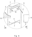
- Fig. 5 shows, by a vector, the momentum of wind 13 that is generated by the track 8 traveling in the inbound lane 2.
- the wind 13 blowing toward the outbound traveling direction 3A is generated in the rear of the track 8 traveling in the inbound lane 2.
- the wind 13 has a certain range, and a part of this wind blows on the front surface 12 of the blade 7 and is guided sequentially by the flat surface 12b and the curved surface 12a of the front surface 12 into the outbound lane 3.
- the momentum in the same direction as the outbound traveling direction 3A is applied to air flow P that is away from the front surface 12 of the blade 7.
- FIG. 6 shows, by a vector, the momentum of wind 14 that is generated by the track 9 traveling in the outbound lane 3.
- the wind 14 blowing to the outbound traveling direction 3A is generated in the rear of the track 9 traveling in the outbound lane 3.
- the wind 14 has a certain range, and a part of the wind blows on the back surface 11 of the blade 7 and is guided sequentially by the flat surface 11b and the curved surface 11a of the back surface 11 into the inbound lane 2.
- the momentum in the same direction as the inbound traveling direction 2A is applied to air flow Q that is away from the back surface 11 of the blade 7.
- Fig. 7 shows test conductions of this test.
- the point of measurement is a point that is at 0.5m from the blade 7 toward the inbound lane 2 and at 1m from the ground and a point that is at 1m from the blade 7 toward the inbound lane 2 and at 1.2m from the ground.
- the shortest distance between the track 9 and the blade 7 when the track 9 traveling in the outbound lane 3 passes through the blade 7 is 1m.
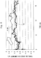
- FIG. 8 is a graph showing test results.
- the horizontal axis of the graph of Fig. 8 indicates time, and the vertical axis indicates the wind speed of the inbound traveling direction 2A component at each point of measurement. Measurement results at the former point are indicated by "0.5m” in the graph, and measurement results at the latter point are indicated by “1m” in the graph.
- the up arrow in Fig. 8 indicates the time when the track 9 passes through the point of measurement.
- Fig. 8 shows that, when the blade 7 is mounted, wind at 1.5m per second at maximum is generated in the inbound lane 2 along the inbound traveling direction 2A as a result that the track 9 travels in the outbound lane 3.
- Fig. 9 is a graph showing test results in the case where the blade 7 is removed for comparison.
- the up arrow in Fig. 9 indicates the time when the track 9 passes through the point of measurement.
- Fig. 9 shows that, when the blade 7 is not mounted, wind at 3m per second at maximum is generated in the inbound lane 2 along the opposite direction from the inbound traveling direction 2A as a result that the track 9 travels in the outbound lane 3.
- a force acting on the track 8 traveling in the inbound lane 2 is calculated by (air resistance) ⁇ (projected area of the track 8) ⁇ (dynamic pressure).
- the dynamic pressure is calculated by 1/2 ⁇ V 2 .
- V indicates the wind speed, and when the track 8 is traveling at 100km per hour, for example, wind at 100km per hour, which is 27.8m per second, is blowing on the track 8.
- the fuel economy increases by about 3% if the air resistance is reduced by 10%, and therefore the fuel economy increases by about 2% when the air resistance is reduced by 7%.
- the fuel efficiency enhancement effect of about 2% can be obtained when wind at about 1m per second is generated in the inbound lane 2 along the inbound traveling direction 2A.
- the first embodiment which is described above, has the following advantageous effects.
- the blades 7 are placed between the inbound lane 2 (first lane) and the outbound lane 3 (second lane), which is the opposite lane of the inbound lane 2.
- the blade 7 has the back surface 11 (first wall surface) facing the same direction as the inbound traveling direction 2A and the front surface 12 (second wall surface) facing the same direction as the outbound traveling direction 3A.
- the back surface 11 is concave in the same direction as the outbound traveling direction 3A so as to change wind blowing from the outbound lane 3 into wind having a component in the inbound traveling direction 2A.
- the front surface 12 is concave in the same direction as the inbound traveling direction 2A so as to change wind blowing from the inbound lane 2 into wind having a component in the outbound traveling direction 3A.
- the entire back surface 11 is concave in the same direction as the outbound traveling direction 3A in the above-described first embodiment, only a part of the back surface 11 may be concave in the same direction as the outbound traveling direction 3A. In other words, the back surface 11 only needs to have a concave part that is concave in the same direction as the outbound traveling direction 3A.
- the entire front surface 12 is concave in the same direction as the inbound traveling direction 2A in the above-described first embodiment, only a part of the front surface 12 may be concave in the same direction as the inbound traveling direction 2A. In other words, the front surface 12 only needs to have a concave part that is concave in the same direction as the inbound traveling direction 2A.
- the back surface 11 contains the flat surface 11b and the curved surface 11a.
- the front surface 12 contains the flat surface 12b and the curved surface 12a.
- the blade 7 may be composed of two parts: a part having the back surface 11 and a part having the front surface 12. Those two parts may be coupled together or may be separated from each other.
- the blade 7 has a first curved plate 50 that is curved to be convex toward the outbound traveling direction 3A in the plan view, a flat plate 51 that is inclined toward the inbound traveling direction 2A in the plan view as it goes from the inbound lane 2 to the outbound lane 3, and a second curved plate 52 that is curved to be convex toward the inbound traveling direction 2A in the plan view, in order from the inbound lane 2 to the outbound lane 3 in this embodiment.
- the blade 7 is formed to be substantially S shaped in the plan view.
- the first curved plate 50 has a curved surface 50a facing the inbound traveling direction 2A and a curved surface 50b facing the outbound traveling direction 3A.
- the curved surface 50a and the curved surface 50b are both curved to be convex toward the outbound traveling direction 3A.
- the flat plate 51 has a flat surface 51a facing the inbound traveling direction 2A and a flat surface 51b facing the outbound traveling direction 3A.
- the flat surface 51a and the flat surface 51b are both flat surfaces.
- the second curved plate 52 has a curved surface 52a facing the inbound traveling direction 2A and a curved surface 52b facing the outbound traveling direction 3A.
- the curved surface 52a and the curved surface 52b are both curved to be convex toward the inbound traveling direction 2A.
- a back surface 11 is composed of the curved surface 50a, the flat surface 51a and the curved surface 52a.
- a front surface 12 is composed of the curved surface 50b, the flat surface 51b and the curved surface 52b.
- the first curved plate 50 and the flat plate 51 form a concave part of the back surface 11 that is concave in the same direction as the outbound traveling direction 3A.
- the curved surface 50a and the flat surface 51a of the back surface 11 are concave in the same direction as the outbound traveling direction 3A.
- the flat plate 51 and the second curved plate 52 form a concave part of the front surface 12 that is concave in the same direction as the inbound traveling direction 2A.
- the flat surface 51b and the curved surface 52b of the front surface 12 are concave in the same direction as the inbound traveling direction 2A.
- the first curved plate 50, the flat plate 51 and the second curved plate 52 are formed integrally.
- the blade 7 is formed to be symmetrical about a point in the plan view.
- the blade 7, however, is not limited to be formed to be symmetrical about a point in the plan view.
- the second embodiment which is described above, has the following advantageous effects.
- the blade 7 (structural object for the road) has the first curved plate 50 that is curved to be convex toward the outbound traveling direction 3A in the plan view, the flat plate 51 that is inclined toward the inbound traveling direction 2A in the plan view as it goes from the inbound lane 2 to the outbound lane 3, and the second curved plate 52 that is curved to be convex toward the inbound traveling direction 2A in the plan view, in order from the inbound lane 2 (first lane) to the outbound lane 3 (second lane), and therefore the blade 7 is formed to be substantially S shaped in the plan view.
- the first curved plate 50 and the flat plate 51 form a concave part of the back surface 11 (first wall surface), and the flat plate 51 and the second curved plate 52 form a concave part of the front surface 12 (second wall surface).
- first wall surface first wall surface
- second wall surface second wall surface
- first curved plate 50, the flat plate 51 and the second curved plate 52 are formed integrally. In the above-described structure, it is possible to manufacture the blade 7 at low costs.
- the curved surface 50b of the first curved plate 50 of the blade 7 may have a plurality of ridges 18 extending horizontally.
- an eddy is generated from each ridge 18 toward the inbound traveling direction 2A, which pulls the current R (see Fig. 11 also) with a negative pressure, and it is thereby possible to enhance the wind speed of the inbound traveling direction 2A component of the flow R.
- the curved surface 52a of the second curved plate 5 of the blade 7 may have a plurality of ridges extending horizontally.
- a third embodiment is an useful example which is not covered by the claims, and is described hereinafter with reference to Fig. 13 . Differences of this embodiment from the above-described second embodiment are mainly described hereinafter, and the redundant description is omitted.
- the blade 7 contains the first curved plate 50, the flat plate 51 and the second curved plate 52, and the first curved plate 50, the flat plate 51 and the second curved plate 52 are formed integrally as shown in Fig. 10 .
- the first curved plate 50, the flat plate 51 and the second curved plate 52 are formed separately from one another as shown in Fig. 13 .
- the first curved plate 50 and the flat plate 51 are arranged separately from each other.
- the flat plate 51 and the second curved plate 52 are arranged separately from each other.
- the first curved plate 50 and the flat plate 51 partly overlap in this order.
- the first curved plate 50 and the flat plate 51 partly face each other.
- the flat plate 51 and the second curved plate 52 partly overlap in this order.
- the flat plate 51 and the second curved plate 52 partly face each other.
- the inbound side wall 5 is described hereinafter with reference to Fig. 14 .
- the inbound side wall 5 has a plurality of inclined surfaces 30 arranged along the inbound lane 2.
- Each inclined surface 30 is inclined toward the inbound lane 2 as it goes toward the inbound traveling direction 2A in the plan view.
- Wind that is generated by traveling of the track 8, which is a leading vehicle, and blows on the inbound side wall 5 is guided by the plurality of inclined surfaces 30, and thereby the wind flows back into the inbound lane 2, maintaining the momentum in the inbound traveling direction 2A.
- the outbound side wall 6, like the inbound side wall 5, has a plurality of inclined surfaces arranged along the outbound lane 3. Each inclined surface is inclined toward the outbound lane 3 as it goes toward the outbound traveling direction 3A in the plan view.
- the inbound side wall 5 has a depression 31 between the two adjacent inclined surfaces 30 in the inbound traveling direction 2A.
- wind that is generated by traveling of the track 8, which is a leading vehicle, and blows on the inbound side wall 5 becomes a spiral flow W that is counterclockwise in the plan view, and it is temporarily held in the depression 31 and then flows back into the inbound lane 2.
- the wind generator 15 is described hereinafter. As shown in Fig. 1 , the wind generator 15 is placed between the two adjacent blades 7. As shown in Figs. 5 and 6 , in the space between the two adjacent blades 7, air flow generated by traveling of the track 8 and air flow generated by traveling of the track 9 are both clockwise in the plan view. Thus, by placing the vertical axis wind generator 15 between the two adjacent blades 7, it is possible to efficiently generate electricity.
- the blade 7 is mounted between an inbound lane 2 and an outbound lane 3, which is the opposite lane of the inbound lane 2.
- the blade 7 has a back surface 11 facing the same direction as an inbound traveling direction 2A and a front surface 12 facing the same direction as an outbound traveling direction 3A.
- the back surface 11 has a concave part that is concave in the same direction as the outbound traveling direction 3A in order to change wind blowing from the outbound lane 3 into wind having a component of the inbound traveling direction 2A.
- the front surface 12 has a concave part that is concave in the same direction as the inbound traveling direction 2A in order to change wind blowing from the inbound lane 2 into wind having a component of the outbound traveling direction 3A.
Landscapes
- Engineering & Computer Science (AREA)
- Architecture (AREA)
- Civil Engineering (AREA)
- Structural Engineering (AREA)
- Life Sciences & Earth Sciences (AREA)
- Sustainable Development (AREA)
- Sustainable Energy (AREA)
- Chemical & Material Sciences (AREA)
- Combustion & Propulsion (AREA)
- Mechanical Engineering (AREA)
- General Engineering & Computer Science (AREA)
- Wind Motors (AREA)
- Devices Affording Protection Of Roads Or Walls For Sound Insulation (AREA)
- Refuge Islands, Traffic Blockers, Or Guard Fence (AREA)
Claims (6)
- Strukturobjekt (7) für eine Straße, das zwischen einer ersten Fahrbahn (2) und einer zweiten Fahrbahn (3) montiert wird, die eine zu der ersten Fahrbahn (2) entgegengesetzte Fahrbahn ist, mit:einer ersten Wandfläche (11), die in die gleiche Richtung wie die Fahrrichtung (2A) der ersten Fahrbahn (2) gewandt ist; undeiner zweiten Wandfläche (12), die in die gleiche Richtung wie eine Fahrrichtung (3A) der zweiten Fahrbahn (3) gerichtet ist, wobeidie erste Wandfläche (11) einen konkaven Abschnitt hat, der in der gleichen Richtung wie die Fahrrichtung (3A) der zweiten Fahrbahn (3) konkav ist, um eine Luftströmung, die von der zweiten Fahrbahn (3) bläst, in eine Luftströmung mit einer Komponente in der Fahrrichtung (2A) der ersten Fahrrichtung (2) zu ändern, unddie zweite Wandfläche (12) einen konkaven Abschnitt hat, der in der gleichen Richtung wie die Fahrrichtung (2A) der ersten Fahrbahn (2) konkav ist, um eine Luftströmung, die von der ersten Fahrbahn (2) bläst, in eine Luftströmung mit einer Komponente in der Fahrrichtung der zweiten Fahrbahn (3) zu ändern,dadurch gekennzeichnet, dassdie gesamte erste Wandfläche (11) in der gleichen Richtung wie die Fahrrichtung (3A) der zweiten Fahrbahn (3) konkav ist,die gesamte zweite Wandfläche (12) in der gleichen Richtung wie die Fahrrichtung (2A) der ersten Fahrbahn (2) konkav ist,die erste Wandfläche (11) eine flache Fläche (11b) und eine gekrümmte Fläche (11a) enthält, unddie zweite Wandfläche (12) eine flache Fläche (12b) und eine gekrümmte Fläche (12a) enthält, so dass es möglich ist, eine Luftströmung, die von der hinausführenden Fahrbahn (3) bläst, in eine Luftströmung mit einer Komponente in der hineinführenden Fahrrichtung (2A) zu ändern, und es außerdem möglich ist, eine Luftströmung, die von der Innenfahrbahn (2) bläst, in eine Luftströmung mit einer Komponente der hinausführenden Fahrrichtung (3A) zu ändern.
- Straßenaufbau (1) mit:der ersten Fahrbahn (2);der zweiten Fahrbahn (3); undeiner Vielzahl an Strukturobjekten (7) für eine Straße gemäß Anspruch 1, die zwischen der ersten Fahrbahn (2) und der zweiten Fahrbahn (3) unter spezifischen Abständen entlang der ersten Fahrbahn (2) oder der zweiten Fahrbahn (3) angeordnet sind.
- Straßenaufbau (1) gemäß Anspruch 2, mit:einem Mittelstreifen (4) zwischen der ersten Fahrbahn (2) und der zweiten Fahrbahn (3), wobeidie Vielzahl an Strukturobjekten (7) für die Straße auf dem Mittelstreifen (4) montiert sind.
- Straßenaufbau (1) gemäß Anspruch 2 oder 3, der des Weiteren Folgendes aufweist:
einen Vertikalachsenluftströmungserzeuger (15), der zwischen zwei benachbarten aus der Vielzahl an Strukturobjekten (7) für die Straße angeordnet ist. - Straßenaufbau (1) gemäß einem der Ansprüche 2 bis 4, der des Weiteren Folgendes aufweist:eine Seitenwand (5), die an einer Seite der ersten Fahrbahn (2) entgegengesetzt zu der Seite der ersten Fahrbahn (2), an der die zweite Fahrbahn (3) sich befindet, montiert ist, wobeidie Seitenwand (5) eine Vielzahl an geneigten Flächen (30) hat, die entlang der ersten Fahrbahn (2) angeordnet sind, undjede der geneigten Flächen (30) zu der ersten Fahrbahn (2) in der Draufsicht geneigt ist in Richtung zu der Fahrrichtung (2A) der ersten Fahrbahn (2).
- Straßenaufbau (1) gemäß Anspruch 5, wobei
die Seitenwand (5) eine Vertiefung (31) zwischen benachbarten der Seitenflächen (30) in der Fahrrichtung (2A) der ersten Fahrbahn (2) hat.
Applications Claiming Priority (1)
| Application Number | Priority Date | Filing Date | Title |
|---|---|---|---|
| JP2015152585A JP6330752B2 (ja) | 2015-07-31 | 2015-07-31 | 道路用構造物及びそれを備えた道路構造 |
Publications (2)
| Publication Number | Publication Date |
|---|---|
| EP3124699A1 EP3124699A1 (de) | 2017-02-01 |
| EP3124699B1 true EP3124699B1 (de) | 2018-10-17 |
Family
ID=56321772
Family Applications (1)
| Application Number | Title | Priority Date | Filing Date |
|---|---|---|---|
| EP16176892.4A Not-in-force EP3124699B1 (de) | 2015-07-31 | 2016-06-29 | Strukturobjekt für strassen und strassenstruktur damit |
Country Status (4)
| Country | Link |
|---|---|
| US (1) | US9777449B2 (de) |
| EP (1) | EP3124699B1 (de) |
| JP (1) | JP6330752B2 (de) |
| CN (1) | CN106400705A (de) |
Families Citing this family (3)
| Publication number | Priority date | Publication date | Assignee | Title |
|---|---|---|---|---|
| CN109322791A (zh) * | 2017-07-31 | 2019-02-12 | 中南大学 | 用于车行桥梁的风能发电型风屏障 |
| CN111335090B (zh) * | 2020-03-07 | 2021-12-17 | 中青宏发集团有限公司 | 一种市政道路及其施工方法 |
| CN113652979B (zh) * | 2021-08-25 | 2022-09-23 | 吉林建筑大学 | 桥梁建设用可调节风障 |
Family Cites Families (30)
| Publication number | Priority date | Publication date | Assignee | Title |
|---|---|---|---|---|
| US2985976A (en) * | 1959-11-25 | 1961-05-30 | Wayne L Parker | Wind rotated attention arresting signal |
| US3080937A (en) * | 1960-11-07 | 1963-03-12 | Garbell Res Foundation | Combined acoustic wall and exhaust gas deflector in operation of jet engines |
| US3374763A (en) * | 1965-02-24 | 1968-03-26 | Francis A. Browning | Fluid operated flasher signal |
| US3349674A (en) | 1965-09-27 | 1967-10-31 | Eisen & Metall Ag | Headlight shielding devices |
| JPS5916539Y2 (ja) * | 1980-05-29 | 1984-05-15 | 楢崎造船株式会社 | 風力発電を利用した道路の凍結防止兼遮風装置 |
| JPS5835695Y2 (ja) * | 1980-08-20 | 1983-08-11 | 積水樹脂株式会社 | 防眩板 |
| US4353179A (en) * | 1981-06-09 | 1982-10-12 | Jennings Hugh F | Rotatable sign |
| JPS5885611U (ja) * | 1982-04-30 | 1983-06-10 | 積水樹脂株式会社 | 防眩板 |
| JPS6062525U (ja) * | 1983-10-05 | 1985-05-01 | タキロン株式会社 | 側壁材 |
| USD342036S (en) * | 1991-09-10 | 1993-12-07 | Rushing Hollis B | Glare paddle |
| US5181695A (en) | 1991-09-11 | 1993-01-26 | Arthur W Eugene | Anti-glare shield system for highway median barriers |
| US5613799A (en) * | 1994-01-18 | 1997-03-25 | Guide; David | Rotating flash device and method |
| US5953841A (en) * | 1996-12-27 | 1999-09-21 | Sawyer; Jeffrey C. | Wind driven rotatable display |
| CN1058235C (zh) * | 1998-01-16 | 2000-11-08 | 深圳市思路德实业发展有限公司 | 波形防眩板 |
| US6149338A (en) * | 1998-07-20 | 2000-11-21 | Anderson; John Derrick | Highway barrier |
| JP2001263220A (ja) * | 2000-03-22 | 2001-09-26 | Mitsuru Sakata | 防眩板自体を回転風車とする風力発電機付き防眩板装置。 |
| JP2002227136A (ja) * | 2001-02-05 | 2002-08-14 | National Research Institute For Earth Science & Disaster Prevention Mext | 道路用防風雪柵用風向変換板 |
| NL1019530C2 (nl) | 2001-12-10 | 2003-06-11 | Heijmans Infrastructuur & Mili | Weg met windscherminstallaties. |
| JP3958622B2 (ja) * | 2002-04-25 | 2007-08-15 | 積水樹脂株式会社 | 浮遊粒子状物質捕集方法及び装置 |
| JP4225890B2 (ja) * | 2003-12-26 | 2009-02-18 | 有限会社サンビジネス | 気流制御装置 |
| JP4296981B2 (ja) | 2004-04-16 | 2009-07-15 | 株式会社大林組 | 防風フェンス |
| US7427173B2 (en) * | 2005-09-15 | 2008-09-23 | Taiming Chen | Power generation system utilizing wind draft from vehicular traffic |
| US7566980B2 (en) * | 2006-12-22 | 2009-07-28 | Genedics Clean Energy, Llc | System and method for creating a geothermal roadway utility with alternative energy pumping system |
| DE202008000852U1 (de) * | 2008-01-22 | 2008-03-20 | Gövert, Arne | Verkehrsleitbarke mit Akku-Warnleuchte |
| JP2010163850A (ja) * | 2009-01-19 | 2010-07-29 | Yasuo Ide | 防風壁、および、防風壁を利用した車両の燃費向上方法 |
| CN201553993U (zh) * | 2009-03-16 | 2010-08-18 | 广州华工百川科技股份有限公司 | 一种防眩板 |
| JP2010248959A (ja) | 2009-04-14 | 2010-11-04 | Hideo Sumiyoshi | 空気圧発電方法電車や自動車など動くものの風による力を利用した発電方法。 |
| JP2011094399A (ja) * | 2009-10-30 | 2011-05-12 | Murakami Shokai:Kk | 眩光防止板及び眩光防止装置 |
| JP2011099330A (ja) | 2009-11-04 | 2011-05-19 | Noai Kk | 道路に於ける電気設備に対する電力供給方法と装置 |
| CN201704643U (zh) * | 2010-04-20 | 2011-01-12 | 郑世荣 | 风力发电道路警示组 |
-
2015
- 2015-07-31 JP JP2015152585A patent/JP6330752B2/ja not_active Expired - Fee Related
-
2016
- 2016-06-22 US US15/189,278 patent/US9777449B2/en not_active Expired - Fee Related
- 2016-06-29 EP EP16176892.4A patent/EP3124699B1/de not_active Not-in-force
- 2016-07-28 CN CN201610608753.XA patent/CN106400705A/zh active Pending
Also Published As
| Publication number | Publication date |
|---|---|
| CN106400705A (zh) | 2017-02-15 |
| EP3124699A1 (de) | 2017-02-01 |
| US20170030037A1 (en) | 2017-02-02 |
| JP2017031666A (ja) | 2017-02-09 |
| JP6330752B2 (ja) | 2018-05-30 |
| US9777449B2 (en) | 2017-10-03 |
Similar Documents
| Publication | Publication Date | Title |
|---|---|---|
| US11614068B2 (en) | Airfoil with a vortex generator pair | |
| EP3124699B1 (de) | Strukturobjekt für strassen und strassenstruktur damit | |
| KR101238256B1 (ko) | 중앙분리대 설치타입의 풍력발전시스템 | |
| US9885340B2 (en) | Aerodynamic screen system | |
| KR102284828B1 (ko) | 집진장치 | |
| KR102635374B1 (ko) | 수직축 풍차 및 이것을 구비한 풍력 발전 장치와 조명 설비 | |
| CN111279071B (zh) | 风力发电装置 | |
| JP6797888B2 (ja) | ボルテックスジェネレータ及び風車翼 | |
| KR101718804B1 (ko) | 도로구조물에 설치되는 풍력발전장치 | |
| US9090346B2 (en) | Wing structure and fairing device | |
| JP2007046559A (ja) | 風力発電機用ブレード | |
| US20160138570A1 (en) | Guiding lightning to a lightning receptor | |
| US20130028722A1 (en) | System and Method for Improving Turbine Efficiency using a Frame and Shroud System | |
| JP2004278062A (ja) | 防風雪柵 | |
| TWI697618B (zh) | 風力發電系統 | |
| KR101080124B1 (ko) | 판상형 아파트 옥상에 설치되는 풍력 증강형 발전 시스템 | |
| JP5584741B2 (ja) | 風力発電装置 | |
| WO2008113169A1 (en) | Wind turbine rotor with intake inducing means | |
| KR102321572B1 (ko) | 중앙분리대형 풍력 발전 시스템 | |
| CN210460730U (zh) | 一种螺旋隧道通风系统 | |
| JP7120795B2 (ja) | 静電アンテナ | |
| JP2005133545A (ja) | 風力発電装置付き建築物 | |
| KR20250084500A (ko) | 빌딩풍 저감 건물 구조 | |
| JP5829583B2 (ja) | 風車用翼体、風車及び風力発電装置 | |
| JP2008063723A (ja) | 防雪柵および防雪柵の吹き払い効果の向上方法 |
Legal Events
| Date | Code | Title | Description |
|---|---|---|---|
| PUAI | Public reference made under article 153(3) epc to a published international application that has entered the european phase |
Free format text: ORIGINAL CODE: 0009012 |
|
| STAA | Information on the status of an ep patent application or granted ep patent |
Free format text: STATUS: REQUEST FOR EXAMINATION WAS MADE |
|
| 17P | Request for examination filed |
Effective date: 20160629 |
|
| AK | Designated contracting states |
Kind code of ref document: A1 Designated state(s): AL AT BE BG CH CY CZ DE DK EE ES FI FR GB GR HR HU IE IS IT LI LT LU LV MC MK MT NL NO PL PT RO RS SE SI SK SM TR |
|
| AX | Request for extension of the european patent |
Extension state: BA ME |
|
| STAA | Information on the status of an ep patent application or granted ep patent |
Free format text: STATUS: EXAMINATION IS IN PROGRESS |
|
| 17Q | First examination report despatched |
Effective date: 20170807 |
|
| GRAP | Despatch of communication of intention to grant a patent |
Free format text: ORIGINAL CODE: EPIDOSNIGR1 |
|
| STAA | Information on the status of an ep patent application or granted ep patent |
Free format text: STATUS: GRANT OF PATENT IS INTENDED |
|
| INTG | Intention to grant announced |
Effective date: 20180504 |
|
| RIN1 | Information on inventor provided before grant (corrected) |
Inventor name: TADAKUMA, KENJI |
|
| GRAS | Grant fee paid |
Free format text: ORIGINAL CODE: EPIDOSNIGR3 |
|
| GRAA | (expected) grant |
Free format text: ORIGINAL CODE: 0009210 |
|
| STAA | Information on the status of an ep patent application or granted ep patent |
Free format text: STATUS: THE PATENT HAS BEEN GRANTED |
|
| AK | Designated contracting states |
Kind code of ref document: B1 Designated state(s): AL AT BE BG CH CY CZ DE DK EE ES FI FR GB GR HR HU IE IS IT LI LT LU LV MC MK MT NL NO PL PT RO RS SE SI SK SM TR |
|
| REG | Reference to a national code |
Ref country code: GB Ref legal event code: FG4D |
|
| REG | Reference to a national code |
Ref country code: CH Ref legal event code: EP |
|
| REG | Reference to a national code |
Ref country code: IE Ref legal event code: FG4D |
|
| REG | Reference to a national code |
Ref country code: DE Ref legal event code: R096 Ref document number: 602016006414 Country of ref document: DE Ref country code: AT Ref legal event code: REF Ref document number: 1054195 Country of ref document: AT Kind code of ref document: T Effective date: 20181115 |
|
| REG | Reference to a national code |
Ref country code: DE Ref legal event code: R084 Ref document number: 602016006414 Country of ref document: DE |
|
| REG | Reference to a national code |
Ref country code: NL Ref legal event code: FP |
|
| REG | Reference to a national code |
Ref country code: GB Ref legal event code: 746 Effective date: 20181126 |
|
| REG | Reference to a national code |
Ref country code: LT Ref legal event code: MG4D |
|
| REG | Reference to a national code |
Ref country code: AT Ref legal event code: MK05 Ref document number: 1054195 Country of ref document: AT Kind code of ref document: T Effective date: 20181017 |
|
| PG25 | Lapsed in a contracting state [announced via postgrant information from national office to epo] |
Ref country code: IS Free format text: LAPSE BECAUSE OF FAILURE TO SUBMIT A TRANSLATION OF THE DESCRIPTION OR TO PAY THE FEE WITHIN THE PRESCRIBED TIME-LIMIT Effective date: 20190217 Ref country code: FI Free format text: LAPSE BECAUSE OF FAILURE TO SUBMIT A TRANSLATION OF THE DESCRIPTION OR TO PAY THE FEE WITHIN THE PRESCRIBED TIME-LIMIT Effective date: 20181017 Ref country code: LV Free format text: LAPSE BECAUSE OF FAILURE TO SUBMIT A TRANSLATION OF THE DESCRIPTION OR TO PAY THE FEE WITHIN THE PRESCRIBED TIME-LIMIT Effective date: 20181017 Ref country code: AT Free format text: LAPSE BECAUSE OF FAILURE TO SUBMIT A TRANSLATION OF THE DESCRIPTION OR TO PAY THE FEE WITHIN THE PRESCRIBED TIME-LIMIT Effective date: 20181017 Ref country code: HR Free format text: LAPSE BECAUSE OF FAILURE TO SUBMIT A TRANSLATION OF THE DESCRIPTION OR TO PAY THE FEE WITHIN THE PRESCRIBED TIME-LIMIT Effective date: 20181017 Ref country code: NO Free format text: LAPSE BECAUSE OF FAILURE TO SUBMIT A TRANSLATION OF THE DESCRIPTION OR TO PAY THE FEE WITHIN THE PRESCRIBED TIME-LIMIT Effective date: 20190117 Ref country code: BG Free format text: LAPSE BECAUSE OF FAILURE TO SUBMIT A TRANSLATION OF THE DESCRIPTION OR TO PAY THE FEE WITHIN THE PRESCRIBED TIME-LIMIT Effective date: 20190117 Ref country code: PL Free format text: LAPSE BECAUSE OF FAILURE TO SUBMIT A TRANSLATION OF THE DESCRIPTION OR TO PAY THE FEE WITHIN THE PRESCRIBED TIME-LIMIT Effective date: 20181017 Ref country code: ES Free format text: LAPSE BECAUSE OF FAILURE TO SUBMIT A TRANSLATION OF THE DESCRIPTION OR TO PAY THE FEE WITHIN THE PRESCRIBED TIME-LIMIT Effective date: 20181017 Ref country code: LT Free format text: LAPSE BECAUSE OF FAILURE TO SUBMIT A TRANSLATION OF THE DESCRIPTION OR TO PAY THE FEE WITHIN THE PRESCRIBED TIME-LIMIT Effective date: 20181017 |
|
| PG25 | Lapsed in a contracting state [announced via postgrant information from national office to epo] |
Ref country code: PT Free format text: LAPSE BECAUSE OF FAILURE TO SUBMIT A TRANSLATION OF THE DESCRIPTION OR TO PAY THE FEE WITHIN THE PRESCRIBED TIME-LIMIT Effective date: 20190217 Ref country code: AL Free format text: LAPSE BECAUSE OF FAILURE TO SUBMIT A TRANSLATION OF THE DESCRIPTION OR TO PAY THE FEE WITHIN THE PRESCRIBED TIME-LIMIT Effective date: 20181017 Ref country code: GR Free format text: LAPSE BECAUSE OF FAILURE TO SUBMIT A TRANSLATION OF THE DESCRIPTION OR TO PAY THE FEE WITHIN THE PRESCRIBED TIME-LIMIT Effective date: 20190118 Ref country code: SE Free format text: LAPSE BECAUSE OF FAILURE TO SUBMIT A TRANSLATION OF THE DESCRIPTION OR TO PAY THE FEE WITHIN THE PRESCRIBED TIME-LIMIT Effective date: 20181017 Ref country code: RS Free format text: LAPSE BECAUSE OF FAILURE TO SUBMIT A TRANSLATION OF THE DESCRIPTION OR TO PAY THE FEE WITHIN THE PRESCRIBED TIME-LIMIT Effective date: 20181017 |
|
| PGFP | Annual fee paid to national office [announced via postgrant information from national office to epo] |
Ref country code: NL Payment date: 20190515 Year of fee payment: 4 |
|
| REG | Reference to a national code |
Ref country code: DE Ref legal event code: R097 Ref document number: 602016006414 Country of ref document: DE |
|
| PG25 | Lapsed in a contracting state [announced via postgrant information from national office to epo] |
Ref country code: CZ Free format text: LAPSE BECAUSE OF FAILURE TO SUBMIT A TRANSLATION OF THE DESCRIPTION OR TO PAY THE FEE WITHIN THE PRESCRIBED TIME-LIMIT Effective date: 20181017 Ref country code: DK Free format text: LAPSE BECAUSE OF FAILURE TO SUBMIT A TRANSLATION OF THE DESCRIPTION OR TO PAY THE FEE WITHIN THE PRESCRIBED TIME-LIMIT Effective date: 20181017 |
|
| PGFP | Annual fee paid to national office [announced via postgrant information from national office to epo] |
Ref country code: DE Payment date: 20190618 Year of fee payment: 4 Ref country code: IT Payment date: 20190630 Year of fee payment: 4 |
|
| PLBE | No opposition filed within time limit |
Free format text: ORIGINAL CODE: 0009261 |
|
| STAA | Information on the status of an ep patent application or granted ep patent |
Free format text: STATUS: NO OPPOSITION FILED WITHIN TIME LIMIT |
|
| PG25 | Lapsed in a contracting state [announced via postgrant information from national office to epo] |
Ref country code: EE Free format text: LAPSE BECAUSE OF FAILURE TO SUBMIT A TRANSLATION OF THE DESCRIPTION OR TO PAY THE FEE WITHIN THE PRESCRIBED TIME-LIMIT Effective date: 20181017 Ref country code: SM Free format text: LAPSE BECAUSE OF FAILURE TO SUBMIT A TRANSLATION OF THE DESCRIPTION OR TO PAY THE FEE WITHIN THE PRESCRIBED TIME-LIMIT Effective date: 20181017 Ref country code: RO Free format text: LAPSE BECAUSE OF FAILURE TO SUBMIT A TRANSLATION OF THE DESCRIPTION OR TO PAY THE FEE WITHIN THE PRESCRIBED TIME-LIMIT Effective date: 20181017 Ref country code: SK Free format text: LAPSE BECAUSE OF FAILURE TO SUBMIT A TRANSLATION OF THE DESCRIPTION OR TO PAY THE FEE WITHIN THE PRESCRIBED TIME-LIMIT Effective date: 20181017 |
|
| PGFP | Annual fee paid to national office [announced via postgrant information from national office to epo] |
Ref country code: FR Payment date: 20190510 Year of fee payment: 4 Ref country code: BE Payment date: 20190516 Year of fee payment: 4 |
|
| 26N | No opposition filed |
Effective date: 20190718 |
|
| PG25 | Lapsed in a contracting state [announced via postgrant information from national office to epo] |
Ref country code: SI Free format text: LAPSE BECAUSE OF FAILURE TO SUBMIT A TRANSLATION OF THE DESCRIPTION OR TO PAY THE FEE WITHIN THE PRESCRIBED TIME-LIMIT Effective date: 20181017 |
|
| PG25 | Lapsed in a contracting state [announced via postgrant information from national office to epo] |
Ref country code: MC Free format text: LAPSE BECAUSE OF FAILURE TO SUBMIT A TRANSLATION OF THE DESCRIPTION OR TO PAY THE FEE WITHIN THE PRESCRIBED TIME-LIMIT Effective date: 20181017 |
|
| REG | Reference to a national code |
Ref country code: CH Ref legal event code: PL |
|
| PG25 | Lapsed in a contracting state [announced via postgrant information from national office to epo] |
Ref country code: TR Free format text: LAPSE BECAUSE OF FAILURE TO SUBMIT A TRANSLATION OF THE DESCRIPTION OR TO PAY THE FEE WITHIN THE PRESCRIBED TIME-LIMIT Effective date: 20181017 |
|
| PG25 | Lapsed in a contracting state [announced via postgrant information from national office to epo] |
Ref country code: IE Free format text: LAPSE BECAUSE OF NON-PAYMENT OF DUE FEES Effective date: 20190629 |
|
| PG25 | Lapsed in a contracting state [announced via postgrant information from national office to epo] |
Ref country code: LU Free format text: LAPSE BECAUSE OF NON-PAYMENT OF DUE FEES Effective date: 20190629 Ref country code: LI Free format text: LAPSE BECAUSE OF NON-PAYMENT OF DUE FEES Effective date: 20190630 Ref country code: CH Free format text: LAPSE BECAUSE OF NON-PAYMENT OF DUE FEES Effective date: 20190630 |
|
| REG | Reference to a national code |
Ref country code: DE Ref legal event code: R119 Ref document number: 602016006414 Country of ref document: DE |
|
| REG | Reference to a national code |
Ref country code: NL Ref legal event code: MM Effective date: 20200701 |
|
| GBPC | Gb: european patent ceased through non-payment of renewal fee |
Effective date: 20200629 |
|
| REG | Reference to a national code |
Ref country code: BE Ref legal event code: MM Effective date: 20200630 |
|
| PG25 | Lapsed in a contracting state [announced via postgrant information from national office to epo] |
Ref country code: GB Free format text: LAPSE BECAUSE OF NON-PAYMENT OF DUE FEES Effective date: 20200629 Ref country code: FR Free format text: LAPSE BECAUSE OF NON-PAYMENT OF DUE FEES Effective date: 20200630 Ref country code: NL Free format text: LAPSE BECAUSE OF NON-PAYMENT OF DUE FEES Effective date: 20200701 |
|
| PG25 | Lapsed in a contracting state [announced via postgrant information from national office to epo] |
Ref country code: CY Free format text: LAPSE BECAUSE OF FAILURE TO SUBMIT A TRANSLATION OF THE DESCRIPTION OR TO PAY THE FEE WITHIN THE PRESCRIBED TIME-LIMIT Effective date: 20181017 Ref country code: DE Free format text: LAPSE BECAUSE OF NON-PAYMENT OF DUE FEES Effective date: 20210101 Ref country code: BE Free format text: LAPSE BECAUSE OF NON-PAYMENT OF DUE FEES Effective date: 20200630 |
|
| PG25 | Lapsed in a contracting state [announced via postgrant information from national office to epo] |
Ref country code: HU Free format text: LAPSE BECAUSE OF FAILURE TO SUBMIT A TRANSLATION OF THE DESCRIPTION OR TO PAY THE FEE WITHIN THE PRESCRIBED TIME-LIMIT; INVALID AB INITIO Effective date: 20160629 Ref country code: MT Free format text: LAPSE BECAUSE OF FAILURE TO SUBMIT A TRANSLATION OF THE DESCRIPTION OR TO PAY THE FEE WITHIN THE PRESCRIBED TIME-LIMIT Effective date: 20181017 |
|
| PG25 | Lapsed in a contracting state [announced via postgrant information from national office to epo] |
Ref country code: IT Free format text: LAPSE BECAUSE OF NON-PAYMENT OF DUE FEES Effective date: 20200629 |
|
| PG25 | Lapsed in a contracting state [announced via postgrant information from national office to epo] |
Ref country code: MK Free format text: LAPSE BECAUSE OF FAILURE TO SUBMIT A TRANSLATION OF THE DESCRIPTION OR TO PAY THE FEE WITHIN THE PRESCRIBED TIME-LIMIT Effective date: 20181017 |