EP3124696B1 - Dispositif d'appui de rail - Google Patents
Dispositif d'appui de rail Download PDFInfo
- Publication number
- EP3124696B1 EP3124696B1 EP15179181.1A EP15179181A EP3124696B1 EP 3124696 B1 EP3124696 B1 EP 3124696B1 EP 15179181 A EP15179181 A EP 15179181A EP 3124696 B1 EP3124696 B1 EP 3124696B1
- Authority
- EP
- European Patent Office
- Prior art keywords
- rail support
- rail
- support device
- clamping bar
- girder
- Prior art date
- Legal status (The legal status is an assumption and is not a legal conclusion. Google has not performed a legal analysis and makes no representation as to the accuracy of the status listed.)
- Active
Links
- 230000007246 mechanism Effects 0.000 claims description 12
- 238000006073 displacement reaction Methods 0.000 claims description 9
- 238000003825 pressing Methods 0.000 claims description 8
- 238000000151 deposition Methods 0.000 claims 1
- 230000000712 assembly Effects 0.000 description 9
- 238000000429 assembly Methods 0.000 description 9
- 210000000078 claw Anatomy 0.000 description 8
- 230000008901 benefit Effects 0.000 description 7
- 230000000903 blocking effect Effects 0.000 description 7
- 238000011161 development Methods 0.000 description 6
- 230000018109 developmental process Effects 0.000 description 6
- 239000012530 fluid Substances 0.000 description 5
- 230000006835 compression Effects 0.000 description 4
- 238000007906 compression Methods 0.000 description 4
- 238000010276 construction Methods 0.000 description 4
- 230000000694 effects Effects 0.000 description 4
- 238000003860 storage Methods 0.000 description 4
- 230000009471 action Effects 0.000 description 3
- 239000002981 blocking agent Substances 0.000 description 3
- 230000003993 interaction Effects 0.000 description 3
- 238000005096 rolling process Methods 0.000 description 3
- 229920001875 Ebonite Polymers 0.000 description 2
- 238000000418 atomic force spectrum Methods 0.000 description 2
- 230000005489 elastic deformation Effects 0.000 description 2
- 238000004519 manufacturing process Methods 0.000 description 2
- 101100390736 Danio rerio fign gene Proteins 0.000 description 1
- 241001669679 Eleotris Species 0.000 description 1
- 101100390738 Mus musculus Fign gene Proteins 0.000 description 1
- 238000005452 bending Methods 0.000 description 1
- 230000015572 biosynthetic process Effects 0.000 description 1
- 239000003795 chemical substances by application Substances 0.000 description 1
- 230000001419 dependent effect Effects 0.000 description 1
- 238000009826 distribution Methods 0.000 description 1
- 230000006872 improvement Effects 0.000 description 1
- 230000001105 regulatory effect Effects 0.000 description 1
- 230000008439 repair process Effects 0.000 description 1
- 238000007493 shaping process Methods 0.000 description 1
- 230000009466 transformation Effects 0.000 description 1
- 230000001960 triggered effect Effects 0.000 description 1
- 238000003466 welding Methods 0.000 description 1
Images


Classifications
-
- E—FIXED CONSTRUCTIONS
- E01—CONSTRUCTION OF ROADS, RAILWAYS, OR BRIDGES
- E01B—PERMANENT WAY; PERMANENT-WAY TOOLS; MACHINES FOR MAKING RAILWAYS OF ALL KINDS
- E01B29/00—Laying, rebuilding, or taking-up tracks; Tools or machines therefor
- E01B29/16—Transporting, laying, removing, or replacing rails; Moving rails placed on sleepers in the track
Definitions
- the present invention relates to a rail support device having the features of the preamble of claim 1.
- Such rail support devices are used to transport railroad tracks on rail transport cars assembled on rail transport trains.
- already prepared or prefabricated long rails (these are rail sections of up to several hundred meters in length) are transported, in particular from short rails in a rail welding plant, for example to track construction sites, to be laid there in the track and connected to the rail infrastructure.
- the long rails are typically lined up in several layers on vertically stacked support beams, which extend transversely to a longitudinal direction of the rail transport cars strung.
- Such rail support devices are for example from the DE 43 12 964 A1 , of the DE 44 18 376 A1 or the DE 20 2004 019 248 U1 known. In the rail support devices known from these publications, however, the rails are exposed in the uppermost layer with their rail heads arranged in the vertical direction and not further secured.
- the rail support devices in which in two U-shaped profiled, vertically extending, with the openings of the U-profiles facing each other support beams for the circulation of Rails can be introduced and can be provided with a clamping bar, which is placed on the top layer of the recorded rails and by means of clamping screws, which project through threaded rods, the openings in the outer ends of the clamping bar, and can be pressed against the top rail layer.
- clamping bar rail transport pads are arranged distributed in this concept only at greater distances on the rail transport car, before and behind are rail transport pads without such clamping beams and no jamming of the laid rails so as to allow evasion of the rails in cornering and damage the transported Rails due to high bending moments in the intermediate area to prevent short clamping distances.
- the fixing and jamming of the clamping bar by means of the screw connections is complex and in turn requires the use of special tools, namely a correspondingly sized mouth or ring wrench for tightening or loosening the nut.
- the applied clamping forces can also be set only insufficiently reproducible, which is also considered to be disadvantageous.
- the clamping bar in the known, above-described solution has on its side facing the support on the rail heads of the uppermost layer of the recorded in the rail support device rails a wooden board, with which it rests on the rail heads. It can be observed that on the one hand by given due to manufacturing tolerances different dimensions of the rails (especially in the rail height, measured from the level of the rail foot to the level of the rail head), on the other hand by inaccurate shaping of the wooden board on the side by side in the uppermost layer of the rails In the rail support device recorded rails different pressure forces are exercised. In this case, it may even happen that, despite a distortion of the clamping bar against the top rail position individual rails experience little or even no significant pressure, so not, as desired, be securely fixed by the clamping bar. Here, too, there is a need for improvement.
- a rail support device with supports (102,104), basic threshold (2a), clamping bar (26), clamping mechanism (4), bearing surface (58) of the clamping bar (26) displaceable relative to a body of the clamping bar (26) in the vertical direction, and means Actuator (70) is actively fed towards the rail support surface is from the JP 2000 108 896 A known. Accordingly, it is an object of the present invention, a rail support device of the type mentioned above, which has a clamping bar in combination with a clamping mechanism for applying a clamping force on the uppermost layer of rails in the rail support device to specify that is simplified in handling and has improved reliability in terms of clamping action.
- the novel rail support device thus - this first in accordance with the prior art - two opposing, a support area laterally bounding vertical supports, extending in a vertically lower portion between the supports basic threshold, on a top a rail support surface for the Shutdown of rails defines a horizontal bar arranged above the base, which is mountable on a bottom surface of a bearing surface for engaging rail heads of a layer of rails deposited on the rail support device, and a tensioning mechanism for applying vertically between the base rail and the clamping bar acting clamping force.
- the novel rail support device now differs from the known prior art in that the rail support surface is displaceable relative to a body of the basic threshold in the vertical direction and that the bearing surface is displaceable relative to a body of the clamping bar in the vertical direction, wherein one of said surfaces, ie the rail support surface or the bearing surface, by means of a drive active in the direction of the other surface, ie the bearing surface or the rail support surface, can be fed and wherein the other surface, ie the bearing surface or the rail support surface, via an elastic return means in the direction of the one by means of the drive actively in the direction of the other surface deliverable surface, ie the rail support surface or the bearing surface, is biased.
- the drive is a hydraulically operated drive.
- a hydraulically actuated drive has the advantage that large forces can be generated and transmitted with it.
- what is provided according to a further advantageous development of the invention can be designed as a manually operated drive, if it has, for example, a hydraulic hand pump.
- This form of design of the drive allows training without the need of supplying a power supply from outside, such as a power supply, so that the rail support device according to the invention can ultimately be designed and formed as a self-sufficient unit.
- the elastic return means may advantageously comprise spring packs which are arranged between the surface provided with the elastic return means, that is to say the bearing surface or the rail support surface, and a housing in which this surface can be displaced in the vertical direction.
- DeIndia spring packages can be structurally comparatively easy to implement, they can be formed, for example, as a cup spring packages. Due to the design with several such spring assemblies, in particular in the element in which they are installed (basic threshold or clamping bar) in the respective longitudinal direction of this element, ie in the direction in which the vertical supports face each other, can be arranged one behind the other at different positions, a very targeted distribution of the clamping force can be achieved. By an individual design and selection of the spring force of the individual spring assemblies can even be influenced on a clamping force profile to thereby make appropriate adjustments to the required clamping force to the required with regard to the horizontal and lateral positioning of the rails position.
- the rail support device in the vertical direction between the base and the clamping bar at least one displaceable on the supports in the vertical direction festlegbarer, extending in the horizontal direction support beams on a bottom a pressure surface for placement on rail heads From below the support beam arranged rails and on a top surface has a bearing surface for the parking of rails mounted on the support beam.
- a support beam allows the inclusion of rails in the rail support device in a further vertical stack level, so that a correspondingly larger number of rails can be stored on the rail support device. It is important that the support beam on the supports in the vertical direction can be fixed displaced.
- a clamping force is applied, applied to the superimposed planes of the applied rails and transmitted vertically on and on supporting beams.
- more than one such support beam for example, two such support beams may be provided so that even more vertically stacked layers of rails can be stacked for transport, in two support beams so according to three rail layers.
- the one or the plurality of support beams can be fixed to one of the supports pivotable about its vertical axis.
- Such a construction allows the support beams, which in this embodiment may also be referred to as "rotation thresholds", not to have to be lifted altogether from the vertically extending supports in order to load or unload rails onto the rail support device. Rather, the support beams can simply be pivoted about the vertical axis of the support on which they are pivotally mounted, and so are brought out of the overlap with the rails or with the surface provided for the support of the rails, so that the rail support device loading or can be unloaded.
- a slotted guide (or a pivot bearing with such a slotted guide) may be formed, as you in the DE202004019248U1 described and disclosed.
- the pressure surface and / or the bearing surface of this support beam can be provided with an elastic support.
- an elastic support may for example be a hard rubber mat, which is applied to the corresponding surface or introduced into this.
- Such elastic pad can advantageously a more advanced and even improved Fixing cause the applied to the respective surface rails by deformed by the elastic deformation of the support the pressure surface or the bearing surface due to the force applied by the actuator clamping force and thus any occurring due to tolerances in the rail dimensions height differences are compensated, so that is ensured in that all rails are detected with a corresponding clamping effect.
- the clamping bar can be fixed to one of the supports so as to be pivotable about its longitudinal axis. Similar as described above in connection with the optional support beams to be provided, also in connection with the clamping bar such a solution has the advantage that the clamping bar does not have to be lifted off the vertical supports as a whole. Rather, it is sufficient to pivot the clamping bar with less effort and thus release rails arranged thereunder or a surface for the support of rails.
- the clamping bar is fixed to the support not only pivotable about its vertical axis, but continue to be displaced in the vertical direction. Thus, the clamping bar for the training of the pressing force or clamping force can be adjusted accordingly in height.
- clamping bar can also be lifted off the rail position on which it rests when pivoting.
- This lift-off can be assisted, as described above with respect to the optional support beams, by clamping bar lifting means which cause vertical displacement of the clamping bar upon pivotal movement of the clamping bar about the vertical axis of the support on which the clamping bar is pivotally mounted.
- a slide guide can be chosen with advantage, as this example, in the DE 20 2004 019 248 U1 described and disclosed.
- the rail support device in which the rail support surface of the base sleeper and / or the bearing surface of the clamping beam is / are provided with an elastic support.
- an elastic support can in turn be applied to the bearing surface or on the rail support surface or embedded in the surface in question. She can turn For example, have the shape of a hard rubber mat.
- Such an elastic support results in the manner already described above with reference to the analog, for the optionally provided support beam as a design option possible elastic support the advantage of a secured rail for all clamping action by compensating given for example by manufacturing tolerances height differences within rail layers.
- the rail support device of the invention may have a mechanical locking means, which causes the releasable blocking of the delivered with the actuator surface (ie the rail support surface or the bearing surface) in a set by means of the actuator vertical position.
- a mechanical locking means can advantageously when the required or desired clamping force is applied by means of the actuator, block or set the actively moving surface with the actuator in position, so that the actuator can be switched off and not during a period of use, for Example during a transport journey to transport rails, must be kept active to apply or maintain the nuclear power active.
- the blocking means is released and moved from a blocking position into a release position.
- the actuator can be activated to relieve the blocking agent by applying a clamping force and to allow a displacement thereof in the release position.
- the actuator is thus equally provided by such a blocking means with a self-locking, which also holds the once occupied position of the positioned with the actuator element when the actuator is switched powerless.
- the rail support device can in a further advantageous constructive development, in which the clamping bar is arranged to be displaceable on the vertical supports in the vertical direction, on the vertical supports abutment elements, which are arranged above the clamping bar are and which are adjustable in height in the longitudinal direction of the supports.
- This type of configuration allows adjustment of the vertical height position of the clamping bar to adapt to the stacking height of the recorded in the rail support device rails.
- abutment elements can be formed, for example, by an advantageous distrhalfweise secured with lock nuts, screw sleeve, which form a corresponding abutment surface on their the clamping bar surface facing.
- cylindrical holding portions may be formed, which have a larger diameter than a stop portion of the supports, so that the clamping bar with an open, annular receiving area having a more than 180 ° circumferential enclosure and an opening width which is larger than the diameter of the abutment portion of the supports in the abutment portion placed over the support and then by positively advancing such an abutment member in a manner that the cylindrical holding portion enters into the annular receiving area, can be positively locked.
- the rail support surface in the basic threshold be that which can be actively fed by means of the drive in the direction of the bearing surface, whereas the bearing surface is biased in the clamping bar via the elastic return means in the direction of the rail support surface.
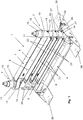
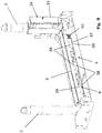
- a rail support device is generally designated by the reference numeral 1 in the figures. It contains as essential elements two mutually opposite spaced apart, with their longitudinal direction vertically extending supports 2 and 3 and a horizontally extending, the distance between the supports 2, 3 in a lower portion of the rail support device 1 bridging basic threshold 4th In the basic threshold a rail support surface 5 is formed, which is displaceable relative to a body 6 of the base threshold 4 in the vertical direction.
- a clamping bar 7 can be seen in the FIGS. 1 . 2 . 8th and 13 in a distance between the supports 2 and 3 bridging, shown at two supports 2, 3 position is shown.
- This Clamping bar 7 has on a bottom of the base 6 facing a bearing surface 8, which rests in operation of the rail support device 1 with rails arranged thereon on rail heads of an uppermost layer of rails.
- This bearing surface 8 is displaceable relative to a body 9 of the clamping bar 7 in the vertical direction.
- the clamping bar 7 itself is pivotally mounted on the vertical support 2 and also displaceable in the vertical direction with a circular cross-section support 2 embracing, integrally formed on the clamping bar 7 bearing sleeve 10.
- a partially formed in cross-section retaining claw 11 engages in the in FIGS. 1 . 2 . 8th and 13 shown position of the clamping bar 7, the vertical support 3.
- the clamping bar 7 from the in the FIGS. 1 . 2 . 8th and 13 shown position to release the underlying area around the support 2 are given away.
- the bearing sleeve 10 of course remains connected to the support 2. In such a pivoting movement in a in the representation of FIG.
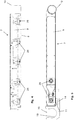
- FIG. 14 A representation of the position in which the clamping bar 7 is pivoted into an open position, is in Fig. 14 shown. In this position, the clamping bar 7 is placed on a formed on a storage support 47 pad 48, so that the bearing sleeve 10 does not permanently bear the weight of the support bar 7 at the end of a one-armed lever.
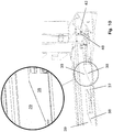
- the retaining claw 11 is provided with a part-annular recess 19 whose circumferential extent is over 180 °. Via an access opening 20, an abutment portion of the support 3, whose diameter is selected so that it can be performed through the access opening 20, are introduced into the recess 19.
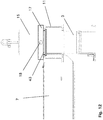
- the threaded sleeve 16 has a reduced in diameter relative to the diameter of the stop collar 17, down over the stop collar 17 projecting cylindrical extension 43 (see Fig. 12 ), which is formed in its diameter corresponding to the diameter of the part-annular recess 19, so that this extension can be introduced into the recess 19 from above.
- cylindrical extension 43 By a corresponding displacement of the screw 16 in the vertical direction downwards by screwing them so this cylindrical extension 43 can be introduced into the recess 19 and then locked due to the over 180 ° encompassing coverage of the recess 19, the retaining claw 11 form-fitting manner.
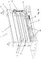
- two supporting beams 21 are arranged in this embodiment. These each have a bearing surface 22 on its upper side, can be placed on the rails with their rail feet. On their underside, the support beams 21 each have a pressure surface 23, with which they rest on rail heads of a arranged below the respective support beam 21 rail position.
- the support beams 21 are arranged in a similar manner to the support 2 pivotable and vertically displaceable as the clamping bar 7.
- the support beams 21 each have a bearing sleeve 24 which encloses the circular cross-section support 2. At the support 3, the support beams 21 in the in the FIGS. 1 . 2 . 8th and 13 shown position releasably fixed by means of locking elements 25.
- the bearing sleeves 24 of the support beams 21 have on their respective underside a slide track 26 which cooperates with a corresponding, fixed to the support 2 rolling pin 27.
- the pivoted in an open position positions of the support beams 21 are in Fig. 14 to recognize.
- the support beams 21 are stored on supports 48 of the storage support 47.
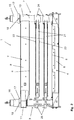
- This clamping mechanism comprises the vertically displaceable rail support surface 5, an actuator to be explained in more detail below for active vertical displacement of the rail support surface 5 in the direction of the clamping bar 7, the bearing surface 8 and an elastic return means which the bearing surface 8 in the direction of the base threshold 4 in the vertical direction biases.
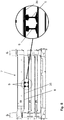
- the elastic return means consists in this embodiment, in particular FIG. 4 can be seen from a number of longitudinally of the clamping bar 7 successively arranged spring assemblies 28, which exert a correspondingly elastic restoring force on the bearing surface 8.
- These spring assemblies 28 each have a plurality of disc springs 29, which are arranged one above the other to the spring assemblies 28 are connected.
- FIG. 7 is shown in enlarged detail representation of such a spring assembly 28 again in more detail. It is formed by the superimposed and placed over a pin 30 plate springs 29 and placed on the disc springs 29, serving as a stop guide bush 31 which is fixed with a castle nut 32 which is screwed onto the bolt 30 and held in position.
- the individual spring assemblies 28 can be adjusted in the longitudinal direction of the clamping bar 7 with different spring force, so as to form a restoring force profile.
- the rail support surface 5 is by means of a hand pump 44 (see Fig. 13 ) operated hydraulic drive in the vertical direction relative to the body 6 of the basic threshold 4 displaced.
- a hydraulic fluid reservoir and the hand pump 44 are located in a closable with a door 33 device box 34. Via a valve 49, the flow rate of the hydraulic fluid can be regulated.
- the hydraulic fluid is pressurized and arranged via hydraulic lines 45 in the body 6, on the rail support surface 5 acting hydraulic pressure rams 46 supplied.
- the rail support surface 5 is displaced relative to the body 6 of the base threshold 4 in the vertical direction, namely issued upwards in the direction of the clamping bar 7.
- the clamping bar 7 is placed and placed on the rail heads of the top rail layer.
- the positions of the supporting beams 21 and the clamping bar 7 are then such that the lower supporting beam 21 rests on the rail heads of the rails arranged underneath, the upper supporting beam 21 rests on the rail heads of the rails laid on the lower supporting beam 21 and the clamping bar 7 with its bearing surface 8 rests on the rail heads of the laid on the upper support beam 21 rails.
- the thus applied clamping force leads to an elastic deformation of the spring assemblies 28 and a deflection of the bearing surface 8, wherein the spring assemblies 28 apply a corresponding counterforce and thus exert a force acting in the opposite direction clamping force.
- the clamping force is exerted on the recorded in the rail support device 1 rails in two directions, namely once vertically from bottom to top (by means of the actuator upwardly displaced rail support surface 5) and once from top to bottom (by the force exerted by the spring packs 28 on the bearing surface 8 counterforce).
- the application of the clamping force required for the formation of a secure hold of the rails in the rail support device 1 can be accomplished simply and without a special and complex tool, in particular without a crane or large tools.
- the applied clamping force is evenly distributed and very effective by the force in both directions in the vertical direction opposite directions.
- the bearing surface 8 has an elastic support 35 which elastically deformed during application of the clamping force and so around the rail heads of those rails S sets and fixes against which it rests.
- an elastic support 35 can also be formed on the support beam 21, at least on its pressure surfaces 23. It is also possible to provide the rail support surface 5 and the support surfaces 22 with corresponding elastic supports 35.
- the clamping mechanism of the rail support device 1 may in particular be provided with a blocking means which blocks or locks the rail support surface 5 in a position once set after application of the clamping force by means of the hydraulics and the hand pump 44.
- a blocking means can contribute in particular to the fact that the actuator does not have to remain permanently activated while the rails are held in the rail support device 1 and held clamped.
- the hydraulic system can be relaxed after setting the blocking agent.
- stepped sections 39 are formed, which have equally stepped contact surfaces with the same height gradations and width dimensions.
- the bolt slide is connected via a compression spring 40 which is placed on a shaft 41 formed on the bolt slide 37 and is supported on an abutment, in a in the FIGS. 10 to 11 biased to the left-facing direction, a direction in which the stepped portions 38 fall in a wedge shape.
- the rail support device 1 shown and described in the embodiment shown is typically installed on a rail transport car, to which it is provided with mounting plates 36, which can be bolted to a load-bearing surface of the rail transport vehicle, for example planked with wooden sleepers.
- the rail support device 1 according to the invention is usually arranged with two such devices in a row in a central portion of a rail transport vehicle, the rail transport car is otherwise equipped with conventional and especially not equipped with clamping bar 7 rail support devices.
Claims (14)
- Dispositif d'appui de rail (1) avec- deux poteaux verticaux opposés (2, 3) délimitant latéralement une zone d'appui,- un seuil de sol (4) s'étendant dans une zone verticalement inférieure entre les poteaux (2, 3), définissant sur une surface supérieure une surface d'appui de rail (5) pour ranger les rails (S),- une barre de serrage (7) s'étendant horizontalement au-dessus du seuil de sol (4), fixé sur les poteaux (2, 3), présentant une surface d'appui (8) sur une face inférieure (8) pour monter sur les têtes de rail une couche de rails (S) stockés sur le dispositif d'appui de rail (1),- un mécanisme de tension pour appliquer une force de serrage agissant verticalement entre le seuil de sol (4) et la barre de serrage (7),caractérisé en ce que la surface d'appui de rail (5) est mobile par rapport au corps (6) du seuil de sol (4) dans la direction verticale et en ce que la surface d'appui (8) est mobile dans la direction verticale par rapport à un corps de la barre de serrage (7), tandis que l'une des surfaces, la surface d'appui de rail (5) ou la surface d'appui (8) peut être réglée au moyen d'un entraînement d'actionnement (44, 46) appartenant au mécanisme de tension, activement en direction de l'autre surface respective, surface d'appui (8) ou surface d'appui du rail (5), l'autre surface respective, surface d'appui (8) ou surface d'appui du rail (5) est précontrainte par l'intermédiaire d'un moyen de réinitialisation élastique (28) dans la direction de ladite surface, surface d'appui de rail (5) ou surface d'appui (8),
- Dispositif d'appui de rail (1) selon la revendication 1, caractérisé en ce que l'entraînement d'actionnement (44, 46) est un entraînement d'actionnement à commande hydraulique.
- Dispositif d'appui de rail (1) selon la revendication 2, caractérisé en ce que l'entraînement d'actionnement à commande hydraulique (44, 46) est une pompe manuelle hydraulique.
- Dispositif d'appui de rail (1) selon l'une quelconque des revendications précédentes, caractérisé en ce que le moyen élastique de réinitialisation (28) comprend des paquets de ressort, qui sont agencés entre la surface d'appui (8) ou la surface d'appui de rail (5), surface munie du moyen de réinitialisation élastique (28) et le corps (6) de l'élément dans lequel ladite surface (5, 8) est montée pour se déplacer dans la direction verticale.
- Dispositif d'appui de rail (1) selon l'une quelconque des revendications précédentes, caractérisé en ce que qu'au moins une poutre (21) s'étend dans le sens vertical, qui peut être fixée et déplacée dans la direction verticale par rapport aux poteaux (2, 3), entre le seuil de sol (4) et la barre de serrage (7), qui présente sur un côté inférieur, une surface de pressage (23) devant être montée sur les têtes de rails (S) disposés en dessous de la poutre (21) et sur un côté supérieur, une surface de pression pour la dépose de rails (S), montée sur la poutre (21).
- Dispositif d'appui de rail (1) selon la revendication 5, caractérisé en ce que ladite au moins une poutre (21) est montée contre l'un des poteaux (2) et peut pivoter autour de l'axe vertical de celui-ci.
- Dispositif d'appui de rail (1) selon la revendication 6, caractérisé en ce que la poutre (21) est montée mobile en direction verticale contre le poteau (2) sur lequel il peut pivoter autour de l'axe vertical de celui-ci, tandis que des moyens de levage de poutre (26, 27) sont prévus, qui déclenchent un déplacement vertical de la poutre (21) lorsque la poutre (21) pivote autour du poteau (2) auquel la poutre est fixée et peut pivoter.
- Dispositif d'appui de rail (1) selon l'une quelconque des revendications 5 à 7, caractérisé en ce que la surface de pression (23) et/ou la surface d'appui (22) de ladite au moins une poutre (21) est pourvue d'un capot élastique.
- Dispositif d'appui de rail (1) selon l'une quelconque des revendications précédentes, caractérisé en ce que ladite poutre (21) est montée contre le poteau (2) et peut pivoter autour de l'axe vertical de celui-ci.
- Dispositif d'appui de rail (1) selon la revendication 9, caractérisé en ce que la barre de serrage (7) est montée mobile en direction verticale contre le poteau (2) sur lequel il peut pivoter autour de l'axe vertical de celui-ci, tandis que des moyens de levage de barre de serrage (12, 13) sont prévus, qui déclenchent un déplacement vertical de la poutre (7) lorsque la poutre (7) pivote autour du poteau (2) auquel la poutre est fixée et peut pivoter.
- Dispositif d'appui de rail (1) selon l'une quelconque des revendications précédentes, caractérisé en ce que la surface d'appui de rail (5) du seuil de sol (4) et/ou la surface d'appui (7) de ladite barre de serrage (35) est pourvue d'un capot élastique (35).
- Dispositif d'appui de rail (1) selon l'une quelconque des revendications précédentes, caractérisé en ce qu'il est prévu un moyen de verrouillage mécanique (37, 38, 39) pour verrouiller de manière amovible la surface d'appui de rail (5) ou la surface d'appui (8), surface allouée à l'entraînement d'actionnement (44, 46), dans une position verticale réglée au moyen de l'entraînement d'actionnement (44, 46).
- Dispositif d'appui de rail (1) selon l'une quelconque des revendications précédentes, caractérisé en ce que la barre de serrage (7) est agencée mobile contre le poteau (2, 3) dans la direction verticale et que des éléments de contre-appui (15, 16, 17) sont prévus sur les poteaux verticaux, réglable en hauteur dans la direction longitudinale de celui-ci au-dessus de la barre de serrage (7).
- Dispositif d'appui de rail (1) selon l'une quelconque des revendications précédentes, caractérisé en ce que la surface d'appui de rail (5) peut être réglée activement en direction de la surface d'appui (8) au moyen de l'entraînement d'actionnement (44, 46), et la surface d'appui (8) est précontrainte par l'intermédiaire des moyens élastiques de réinitialisation (28) en direction de la surface d'appui de rail (5).
Priority Applications (6)
| Application Number | Priority Date | Filing Date | Title |
|---|---|---|---|
| PL15179181T PL3124696T3 (pl) | 2015-07-30 | 2015-07-30 | Urządzenie do układania szyn |
| EP15179181.1A EP3124696B1 (fr) | 2015-07-30 | 2015-07-30 | Dispositif d'appui de rail |
| HUE15179181A HUE035401T2 (en) | 2015-07-30 | 2015-07-30 | Cross support |
| NO15179181A NO3124696T3 (fr) | 2015-07-30 | 2015-07-30 | |
| DK15179181.1T DK3124696T3 (da) | 2015-07-30 | 2015-07-30 | Skinnestøtteindretning |
| HRP20180101TT HRP20180101T1 (hr) | 2015-07-30 | 2018-01-19 | Uređaj za podupiranje tračnica |
Applications Claiming Priority (1)
| Application Number | Priority Date | Filing Date | Title |
|---|---|---|---|
| EP15179181.1A EP3124696B1 (fr) | 2015-07-30 | 2015-07-30 | Dispositif d'appui de rail |
Publications (2)
| Publication Number | Publication Date |
|---|---|
| EP3124696A1 EP3124696A1 (fr) | 2017-02-01 |
| EP3124696B1 true EP3124696B1 (fr) | 2017-11-01 |
Family
ID=53773296
Family Applications (1)
| Application Number | Title | Priority Date | Filing Date |
|---|---|---|---|
| EP15179181.1A Active EP3124696B1 (fr) | 2015-07-30 | 2015-07-30 | Dispositif d'appui de rail |
Country Status (6)
| Country | Link |
|---|---|
| EP (1) | EP3124696B1 (fr) |
| DK (1) | DK3124696T3 (fr) |
| HR (1) | HRP20180101T1 (fr) |
| HU (1) | HUE035401T2 (fr) |
| NO (1) | NO3124696T3 (fr) |
| PL (1) | PL3124696T3 (fr) |
Families Citing this family (2)
| Publication number | Priority date | Publication date | Assignee | Title |
|---|---|---|---|---|
| DE102019211452A1 (de) * | 2019-07-31 | 2021-02-04 | Robel Bahnbaumaschinen Gmbh | Lagereinheit zum mehrschichtigen Lagern von Schienen auf einem Schienenladezug sowie modulares Baukastensystem und Verfahren zur Herstellung einer Lagereinheit zum mehrschichtigen Lagern von Schienen auf einem Schienenladezug |
| CN111452812A (zh) * | 2019-11-12 | 2020-07-28 | 中车眉山车辆有限公司 | 一种长钢轨运输作业车组 |
Family Cites Families (5)
| Publication number | Priority date | Publication date | Assignee | Title |
|---|---|---|---|---|
| DE4312964A1 (de) | 1993-04-21 | 1994-10-27 | Robel Georg Gmbh & Co | Schienenverladezug zum Transport sowie zum Auf-und Abladen von Langschienen |
| DE4418376B4 (de) | 1994-05-26 | 2004-02-19 | Robel Bahnbaumaschinen Gmbh | Schienenverladezug zum Transport sowie zum Auf- und Abladen von Langschienen |
| DE29704533U1 (de) * | 1997-03-13 | 1997-06-26 | Robel Georg Gmbh & Co | Zwischenlage zur Höhenmäßigen Distanzierung und Abstützung von Langschienen |
| JP3592103B2 (ja) * | 1998-10-08 | 2004-11-24 | 東海旅客鉄道株式会社 | レール締結装置 |
| DE202004019248U1 (de) | 2004-12-14 | 2005-03-10 | Stahlberg Roensch Gmbh & Co. Kg | Schienenauflagevorrichtung |
-
2015
- 2015-07-30 PL PL15179181T patent/PL3124696T3/pl unknown
- 2015-07-30 EP EP15179181.1A patent/EP3124696B1/fr active Active
- 2015-07-30 DK DK15179181.1T patent/DK3124696T3/da active
- 2015-07-30 HU HUE15179181A patent/HUE035401T2/en unknown
- 2015-07-30 NO NO15179181A patent/NO3124696T3/no unknown
-
2018
- 2018-01-19 HR HRP20180101TT patent/HRP20180101T1/hr unknown
Non-Patent Citations (1)
| Title |
|---|
| None * |
Also Published As
| Publication number | Publication date |
|---|---|
| HUE035401T2 (en) | 2018-05-02 |
| HRP20180101T1 (hr) | 2018-02-23 |
| DK3124696T3 (da) | 2018-01-29 |
| NO3124696T3 (fr) | 2018-03-31 |
| PL3124696T3 (pl) | 2018-05-30 |
| EP3124696A1 (fr) | 2017-02-01 |
Similar Documents
| Publication | Publication Date | Title |
|---|---|---|
| EP2150663A2 (fr) | Dispositif de rangement pour véhicules à moteur | |
| DE2817782C3 (de) | Zungenweiche | |
| DE102015108034A1 (de) | Vorrichtung zur Sicherung von Ladegut | |
| EP3124696B1 (fr) | Dispositif d'appui de rail | |
| EP2074050A1 (fr) | Pont élévateur à colonnes pour véhicules automobiles | |
| DE3236340A1 (de) | Gleisbremse zum abbremsen von eisenbahnwagen | |
| EP2261164A2 (fr) | Dispositif de guidage avec régulation de mouvement rectiligne et centré pour grue équipée de galets de roulement sur chemin de roulement avec rails | |
| DE3019008A1 (de) | Prellbock | |
| DE1630521A1 (de) | Verriegelungsvorrichtung zwischen einem Kasten oder Aufsattel Anhanger und dessen Straßenfahrgestell fur Schienen Straßen Transporte | |
| EP2565147B1 (fr) | Enjambement d'un évidement au sol | |
| DE4229501C2 (de) | Richtrahmen zur Reparatur von Kraftfahrzeugkarosserien | |
| EP1710348B1 (fr) | Dispositif pour poser des traverses en Y | |
| DE102018221360A1 (de) | Automatische Abrollsicherung | |
| DE2414764C3 (de) | Einrichtung zum Kurzkuppeln zweier Fahrwerke eines Schienenfahrzeugs mit Tragschnäbeln | |
| EP0516586B1 (fr) | Dispositif de verrouillage lateral d'une plate-forme tournante sur un wagon ferroviaire | |
| WO1999044876A1 (fr) | Frein de voie, notamment frein de maintien | |
| DE3211941A1 (de) | Kastenaufbau mit einem hubboden, insbesondere fuer viehtransportfahrzeuge | |
| DE19614665C2 (de) | Gleisbremse, insbesondere Gefälleausgleichsbremse | |
| DE193967C (fr) | ||
| DE66824C (de) | Weiche mit senkrecht durch eine Kurbelwelle bewegten Weichenschienen | |
| DE102017100978B4 (de) | Lasthebevorrichtung und Verfahren zur Wartung einer Eisenbahnbrücke | |
| DE1708649A1 (de) | Verfahren und Vorrichtung zum Ausrichten eines Gleises der Seite nach | |
| DE2705826C3 (de) | Stationäre Bremse für auf Schienen geführte Fahrzeuge | |
| DE596666C (de) | Eisenbahnmittelpufferkupplung mit auf der Zugstange zu beiden Seiten der Kopfschwelle des Fahrzeugrahmens angeordneten Stahl- und Gummifedern | |
| WO2003066964A1 (fr) | Dispositif pour regler l'ecartement d'une voie |
Legal Events
| Date | Code | Title | Description |
|---|---|---|---|
| PUAI | Public reference made under article 153(3) epc to a published international application that has entered the european phase |
Free format text: ORIGINAL CODE: 0009012 |
|
| 17P | Request for examination filed |
Effective date: 20160121 |
|
| AK | Designated contracting states |
Kind code of ref document: A1 Designated state(s): AL AT BE BG CH CY CZ DE DK EE ES FI FR GB GR HR HU IE IS IT LI LT LU LV MC MK MT NL NO PL PT RO RS SE SI SK SM TR |
|
| AX | Request for extension of the european patent |
Extension state: BA ME |
|
| RBV | Designated contracting states (corrected) |
Designated state(s): AL AT BE BG CH CY CZ DE DK EE ES FI FR GB GR HR HU IE IS IT LI LT LU LV MC MK MT NL NO PL PT RO RS SE SI SK SM TR |
|
| GRAP | Despatch of communication of intention to grant a patent |
Free format text: ORIGINAL CODE: EPIDOSNIGR1 |
|
| RIC1 | Information provided on ipc code assigned before grant |
Ipc: B61D 45/00 20060101ALI20170522BHEP Ipc: E01B 29/16 20060101AFI20170522BHEP |
|
| INTG | Intention to grant announced |
Effective date: 20170621 |
|
| GRAS | Grant fee paid |
Free format text: ORIGINAL CODE: EPIDOSNIGR3 |
|
| GRAA | (expected) grant |
Free format text: ORIGINAL CODE: 0009210 |
|
| AK | Designated contracting states |
Kind code of ref document: B1 Designated state(s): AL AT BE BG CH CY CZ DE DK EE ES FI FR GB GR HR HU IE IS IT LI LT LU LV MC MK MT NL NO PL PT RO RS SE SI SK SM TR |
|
| AX | Request for extension of the european patent |
Extension state: BA ME |
|
| RAX | Requested extension states of the european patent have changed |
Extension state: BA Payment date: 20170919 Extension state: ME Payment date: 20170919 |
|
| REG | Reference to a national code |
Ref country code: GB Ref legal event code: FG4D Free format text: NOT ENGLISH |
|
| REG | Reference to a national code |
Ref country code: CH Ref legal event code: EP Ref country code: AT Ref legal event code: REF Ref document number: 942152 Country of ref document: AT Kind code of ref document: T Effective date: 20171115 |
|
| REG | Reference to a national code |
Ref country code: IE Ref legal event code: FG4D Free format text: LANGUAGE OF EP DOCUMENT: GERMAN |
|
| REG | Reference to a national code |
Ref country code: DE Ref legal event code: R096 Ref document number: 502015002242 Country of ref document: DE |
|
| REG | Reference to a national code |
Ref country code: DE Ref legal event code: R081 Ref document number: 502015002242 Country of ref document: DE Owner name: VOSSLOH LOGISTICS GMBH, DE Free format text: FORMER OWNER: LOG LOGISTIKGESELLSCHAFT GLEISBAU MBH, 30161 HANNOVER, DE |
|
| REG | Reference to a national code |
Ref country code: HR Ref legal event code: TUEP Ref document number: P20180101 Country of ref document: HR |
|
| RAP2 | Party data changed (patent owner data changed or rights of a patent transferred) |
Owner name: VOSSLOH LOGISTICS GMBH |
|
| REG | Reference to a national code |
Ref country code: RO Ref legal event code: EPE |
|
| REG | Reference to a national code |
Ref country code: DK Ref legal event code: T3 Effective date: 20180125 |
|
| REG | Reference to a national code |
Ref country code: CH Ref legal event code: PFA Owner name: VOSSLOH LOGISTICS GMBH, DE Free format text: FORMER OWNER: LOG LOGISTIKGESELLSCHAFT GLEISBAU MBH, DE |
|
| REG | Reference to a national code |
Ref country code: NL Ref legal event code: FP |
|
| REG | Reference to a national code |
Ref country code: BE Ref legal event code: HC Owner name: VOSSLOH LOGISTICS GMBH; DE Free format text: DETAILS ASSIGNMENT: CHANGE OF OWNER(S), CHANGEMENT DE NOM DU PROPRIETAIRE; FORMER OWNER NAME: LOG LOGISTIKGESELLSCHAFT GLEISBAU MBH Effective date: 20180109 |
|
| REG | Reference to a national code |
Ref country code: SE Ref legal event code: TRGR |
|
| REG | Reference to a national code |
Ref country code: HR Ref legal event code: T1PR Ref document number: P20180101 Country of ref document: HR |
|
| REG | Reference to a national code |
Ref country code: NL Ref legal event code: HC Owner name: VOSSLOH LOGISTICS GMBH; DE Free format text: DETAILS ASSIGNMENT: CHANGE OF OWNER(S), CHANGE OF OWNER(S) NAME; FORMER OWNER NAME: LOG LOGISTIKGESELLSCHAFT GLEISBAU MBH Effective date: 20180123 |
|
| REG | Reference to a national code |
Ref country code: LT Ref legal event code: MG4D Ref country code: NO Ref legal event code: T2 Effective date: 20171101 |
|
| PG25 | Lapsed in a contracting state [announced via postgrant information from national office to epo] |
Ref country code: FI Free format text: LAPSE BECAUSE OF FAILURE TO SUBMIT A TRANSLATION OF THE DESCRIPTION OR TO PAY THE FEE WITHIN THE PRESCRIBED TIME-LIMIT Effective date: 20171101 Ref country code: ES Free format text: LAPSE BECAUSE OF FAILURE TO SUBMIT A TRANSLATION OF THE DESCRIPTION OR TO PAY THE FEE WITHIN THE PRESCRIBED TIME-LIMIT Effective date: 20171101 Ref country code: LT Free format text: LAPSE BECAUSE OF FAILURE TO SUBMIT A TRANSLATION OF THE DESCRIPTION OR TO PAY THE FEE WITHIN THE PRESCRIBED TIME-LIMIT Effective date: 20171101 |
|
| REG | Reference to a national code |
Ref country code: HU Ref legal event code: AG4A Ref document number: E035401 Country of ref document: HU |
|
| PG25 | Lapsed in a contracting state [announced via postgrant information from national office to epo] |
Ref country code: LV Free format text: LAPSE BECAUSE OF FAILURE TO SUBMIT A TRANSLATION OF THE DESCRIPTION OR TO PAY THE FEE WITHIN THE PRESCRIBED TIME-LIMIT Effective date: 20171101 Ref country code: GR Free format text: LAPSE BECAUSE OF FAILURE TO SUBMIT A TRANSLATION OF THE DESCRIPTION OR TO PAY THE FEE WITHIN THE PRESCRIBED TIME-LIMIT Effective date: 20180202 Ref country code: RS Free format text: LAPSE BECAUSE OF FAILURE TO SUBMIT A TRANSLATION OF THE DESCRIPTION OR TO PAY THE FEE WITHIN THE PRESCRIBED TIME-LIMIT Effective date: 20171101 Ref country code: IS Free format text: LAPSE BECAUSE OF FAILURE TO SUBMIT A TRANSLATION OF THE DESCRIPTION OR TO PAY THE FEE WITHIN THE PRESCRIBED TIME-LIMIT Effective date: 20180301 |
|
| REG | Reference to a national code |
Ref country code: FR Ref legal event code: PLFP Year of fee payment: 4 |
|
| PG25 | Lapsed in a contracting state [announced via postgrant information from national office to epo] |
Ref country code: CY Free format text: LAPSE BECAUSE OF FAILURE TO SUBMIT A TRANSLATION OF THE DESCRIPTION OR TO PAY THE FEE WITHIN THE PRESCRIBED TIME-LIMIT Effective date: 20171101 Ref country code: EE Free format text: LAPSE BECAUSE OF FAILURE TO SUBMIT A TRANSLATION OF THE DESCRIPTION OR TO PAY THE FEE WITHIN THE PRESCRIBED TIME-LIMIT Effective date: 20171101 |
|
| REG | Reference to a national code |
Ref country code: SK Ref legal event code: T3 Ref document number: E 27209 Country of ref document: SK Ref country code: DE Ref legal event code: R097 Ref document number: 502015002242 Country of ref document: DE |
|
| PG25 | Lapsed in a contracting state [announced via postgrant information from national office to epo] |
Ref country code: SM Free format text: LAPSE BECAUSE OF FAILURE TO SUBMIT A TRANSLATION OF THE DESCRIPTION OR TO PAY THE FEE WITHIN THE PRESCRIBED TIME-LIMIT Effective date: 20171101 |
|
| PLBE | No opposition filed within time limit |
Free format text: ORIGINAL CODE: 0009261 |
|
| STAA | Information on the status of an ep patent application or granted ep patent |
Free format text: STATUS: NO OPPOSITION FILED WITHIN TIME LIMIT |
|
| PG25 | Lapsed in a contracting state [announced via postgrant information from national office to epo] |
Ref country code: MT Free format text: LAPSE BECAUSE OF FAILURE TO SUBMIT A TRANSLATION OF THE DESCRIPTION OR TO PAY THE FEE WITHIN THE PRESCRIBED TIME-LIMIT Effective date: 20171101 |
|
| 26N | No opposition filed |
Effective date: 20180802 |
|
| PG25 | Lapsed in a contracting state [announced via postgrant information from national office to epo] |
Ref country code: MC Free format text: LAPSE BECAUSE OF FAILURE TO SUBMIT A TRANSLATION OF THE DESCRIPTION OR TO PAY THE FEE WITHIN THE PRESCRIBED TIME-LIMIT Effective date: 20171101 |
|
| REG | Reference to a national code |
Ref country code: IE Ref legal event code: MM4A |
|
| PG25 | Lapsed in a contracting state [announced via postgrant information from national office to epo] |
Ref country code: IE Free format text: LAPSE BECAUSE OF NON-PAYMENT OF DUE FEES Effective date: 20180730 |
|
| REG | Reference to a national code |
Ref country code: HR Ref legal event code: ODRP Ref document number: P20180101 Country of ref document: HR Payment date: 20190724 Year of fee payment: 5 |
|
| PGFP | Annual fee paid to national office [announced via postgrant information from national office to epo] |
Ref country code: LU Payment date: 20190722 Year of fee payment: 5 |
|
| PGFP | Annual fee paid to national office [announced via postgrant information from national office to epo] |
Ref country code: SK Payment date: 20190719 Year of fee payment: 5 Ref country code: RO Payment date: 20190722 Year of fee payment: 5 |
|
| PGFP | Annual fee paid to national office [announced via postgrant information from national office to epo] |
Ref country code: HU Payment date: 20190717 Year of fee payment: 5 Ref country code: BG Payment date: 20190722 Year of fee payment: 5 Ref country code: HR Payment date: 20190724 Year of fee payment: 5 |
|
| GBPC | Gb: european patent ceased through non-payment of renewal fee |
Effective date: 20190730 |
|
| PG25 | Lapsed in a contracting state [announced via postgrant information from national office to epo] |
Ref country code: TR Free format text: LAPSE BECAUSE OF FAILURE TO SUBMIT A TRANSLATION OF THE DESCRIPTION OR TO PAY THE FEE WITHIN THE PRESCRIBED TIME-LIMIT Effective date: 20171101 |
|
| PG25 | Lapsed in a contracting state [announced via postgrant information from national office to epo] |
Ref country code: GB Free format text: LAPSE BECAUSE OF NON-PAYMENT OF DUE FEES Effective date: 20190730 |
|
| PG25 | Lapsed in a contracting state [announced via postgrant information from national office to epo] |
Ref country code: PT Free format text: LAPSE BECAUSE OF FAILURE TO SUBMIT A TRANSLATION OF THE DESCRIPTION OR TO PAY THE FEE WITHIN THE PRESCRIBED TIME-LIMIT Effective date: 20171101 |
|
| PG25 | Lapsed in a contracting state [announced via postgrant information from national office to epo] |
Ref country code: MK Free format text: LAPSE BECAUSE OF NON-PAYMENT OF DUE FEES Effective date: 20171101 |
|
| PG25 | Lapsed in a contracting state [announced via postgrant information from national office to epo] |
Ref country code: AL Free format text: LAPSE BECAUSE OF FAILURE TO SUBMIT A TRANSLATION OF THE DESCRIPTION OR TO PAY THE FEE WITHIN THE PRESCRIBED TIME-LIMIT Effective date: 20171101 |
|
| PGFP | Annual fee paid to national office [announced via postgrant information from national office to epo] |
Ref country code: NL Payment date: 20200729 Year of fee payment: 6 |
|
| PGFP | Annual fee paid to national office [announced via postgrant information from national office to epo] |
Ref country code: NO Payment date: 20200722 Year of fee payment: 6 Ref country code: CZ Payment date: 20200722 Year of fee payment: 6 Ref country code: FR Payment date: 20200727 Year of fee payment: 6 Ref country code: DK Payment date: 20200722 Year of fee payment: 6 |
|
| PG25 | Lapsed in a contracting state [announced via postgrant information from national office to epo] |
Ref country code: SI Free format text: LAPSE BECAUSE OF NON-PAYMENT OF DUE FEES Effective date: 20180730 |
|
| PGFP | Annual fee paid to national office [announced via postgrant information from national office to epo] |
Ref country code: BE Payment date: 20200722 Year of fee payment: 6 Ref country code: AT Payment date: 20200720 Year of fee payment: 6 Ref country code: CH Payment date: 20200724 Year of fee payment: 6 Ref country code: IT Payment date: 20200731 Year of fee payment: 6 Ref country code: SE Payment date: 20200724 Year of fee payment: 6 |
|
| REG | Reference to a national code |
Ref country code: HR Ref legal event code: PBON Ref document number: P20180101 Country of ref document: HR Effective date: 20200730 |
|
| REG | Reference to a national code |
Ref country code: SK Ref legal event code: MM4A Ref document number: E 27209 Country of ref document: SK Effective date: 20200730 |
|
| PG25 | Lapsed in a contracting state [announced via postgrant information from national office to epo] |
Ref country code: LU Free format text: LAPSE BECAUSE OF NON-PAYMENT OF DUE FEES Effective date: 20200730 Ref country code: RO Free format text: LAPSE BECAUSE OF NON-PAYMENT OF DUE FEES Effective date: 20200730 Ref country code: HU Free format text: LAPSE BECAUSE OF NON-PAYMENT OF DUE FEES Effective date: 20200731 |
|
| PG25 | Lapsed in a contracting state [announced via postgrant information from national office to epo] |
Ref country code: BG Free format text: LAPSE BECAUSE OF NON-PAYMENT OF DUE FEES Effective date: 20210131 |
|
| PG25 | Lapsed in a contracting state [announced via postgrant information from national office to epo] |
Ref country code: SK Free format text: LAPSE BECAUSE OF NON-PAYMENT OF DUE FEES Effective date: 20200730 Ref country code: HR Free format text: LAPSE BECAUSE OF NON-PAYMENT OF DUE FEES Effective date: 20200730 |
|
| REG | Reference to a national code |
Ref country code: DK Ref legal event code: EBP Effective date: 20210731 |
|
| REG | Reference to a national code |
Ref country code: CH Ref legal event code: PL Ref country code: NO Ref legal event code: MMEP |
|
| REG | Reference to a national code |
Ref country code: NL Ref legal event code: MM Effective date: 20210801 |
|
| REG | Reference to a national code |
Ref country code: AT Ref legal event code: MM01 Ref document number: 942152 Country of ref document: AT Kind code of ref document: T Effective date: 20210730 |
|
| REG | Reference to a national code |
Ref country code: BE Ref legal event code: MM Effective date: 20210731 |
|
| PG25 | Lapsed in a contracting state [announced via postgrant information from national office to epo] |
Ref country code: LI Free format text: LAPSE BECAUSE OF NON-PAYMENT OF DUE FEES Effective date: 20210731 Ref country code: CH Free format text: LAPSE BECAUSE OF NON-PAYMENT OF DUE FEES Effective date: 20210731 Ref country code: AT Free format text: LAPSE BECAUSE OF NON-PAYMENT OF DUE FEES Effective date: 20210730 |
|
| PG25 | Lapsed in a contracting state [announced via postgrant information from national office to epo] |
Ref country code: SE Free format text: LAPSE BECAUSE OF NON-PAYMENT OF DUE FEES Effective date: 20210731 Ref country code: NO Free format text: LAPSE BECAUSE OF NON-PAYMENT OF DUE FEES Effective date: 20210731 Ref country code: NL Free format text: LAPSE BECAUSE OF NON-PAYMENT OF DUE FEES Effective date: 20210801 Ref country code: FR Free format text: LAPSE BECAUSE OF NON-PAYMENT OF DUE FEES Effective date: 20210731 Ref country code: CZ Free format text: LAPSE BECAUSE OF NON-PAYMENT OF DUE FEES Effective date: 20210730 |
|
| PG25 | Lapsed in a contracting state [announced via postgrant information from national office to epo] |
Ref country code: IT Free format text: LAPSE BECAUSE OF NON-PAYMENT OF DUE FEES Effective date: 20210730 Ref country code: DK Free format text: LAPSE BECAUSE OF NON-PAYMENT OF DUE FEES Effective date: 20210731 Ref country code: BE Free format text: LAPSE BECAUSE OF NON-PAYMENT OF DUE FEES Effective date: 20210731 |
|
| PGFP | Annual fee paid to national office [announced via postgrant information from national office to epo] |
Ref country code: PL Payment date: 20230721 Year of fee payment: 9 Ref country code: DE Payment date: 20230626 Year of fee payment: 9 |