EP3124696B1 - Rail support device - Google Patents
Rail support device Download PDFInfo
- Publication number
- EP3124696B1 EP3124696B1 EP15179181.1A EP15179181A EP3124696B1 EP 3124696 B1 EP3124696 B1 EP 3124696B1 EP 15179181 A EP15179181 A EP 15179181A EP 3124696 B1 EP3124696 B1 EP 3124696B1
- Authority
- EP
- European Patent Office
- Prior art keywords
- rail support
- rail
- support device
- clamping bar
- girder
- Prior art date
- Legal status (The legal status is an assumption and is not a legal conclusion. Google has not performed a legal analysis and makes no representation as to the accuracy of the status listed.)
- Active
Links
- 230000007246 mechanism Effects 0.000 claims description 12
- 238000006073 displacement reaction Methods 0.000 claims description 9
- 238000003825 pressing Methods 0.000 claims description 8
- 238000000151 deposition Methods 0.000 claims 1
- 230000000712 assembly Effects 0.000 description 9
- 238000000429 assembly Methods 0.000 description 9
- 210000000078 claw Anatomy 0.000 description 8
- 230000008901 benefit Effects 0.000 description 7
- 230000000903 blocking effect Effects 0.000 description 7
- 238000011161 development Methods 0.000 description 6
- 230000018109 developmental process Effects 0.000 description 6
- 239000012530 fluid Substances 0.000 description 5
- 230000006835 compression Effects 0.000 description 4
- 238000007906 compression Methods 0.000 description 4
- 238000010276 construction Methods 0.000 description 4
- 230000000694 effects Effects 0.000 description 4
- 238000003860 storage Methods 0.000 description 4
- 230000009471 action Effects 0.000 description 3
- 239000002981 blocking agent Substances 0.000 description 3
- 230000003993 interaction Effects 0.000 description 3
- 238000005096 rolling process Methods 0.000 description 3
- 229920001875 Ebonite Polymers 0.000 description 2
- 238000000418 atomic force spectrum Methods 0.000 description 2
- 230000005489 elastic deformation Effects 0.000 description 2
- 238000004519 manufacturing process Methods 0.000 description 2
- 101100390736 Danio rerio fign gene Proteins 0.000 description 1
- 241001669679 Eleotris Species 0.000 description 1
- 101100390738 Mus musculus Fign gene Proteins 0.000 description 1
- 238000005452 bending Methods 0.000 description 1
- 230000015572 biosynthetic process Effects 0.000 description 1
- 239000003795 chemical substances by application Substances 0.000 description 1
- 230000001419 dependent effect Effects 0.000 description 1
- 238000009826 distribution Methods 0.000 description 1
- 230000006872 improvement Effects 0.000 description 1
- 230000001105 regulatory effect Effects 0.000 description 1
- 230000008439 repair process Effects 0.000 description 1
- 238000007493 shaping process Methods 0.000 description 1
- 230000009466 transformation Effects 0.000 description 1
- 230000001960 triggered effect Effects 0.000 description 1
- 238000003466 welding Methods 0.000 description 1
Images


Classifications
-
- E—FIXED CONSTRUCTIONS
- E01—CONSTRUCTION OF ROADS, RAILWAYS, OR BRIDGES
- E01B—PERMANENT WAY; PERMANENT-WAY TOOLS; MACHINES FOR MAKING RAILWAYS OF ALL KINDS
- E01B29/00—Laying, rebuilding, or taking-up tracks; Tools or machines therefor
- E01B29/16—Transporting, laying, removing, or replacing rails; Moving rails placed on sleepers in the track
Definitions
- the present invention relates to a rail support device having the features of the preamble of claim 1.
- Such rail support devices are used to transport railroad tracks on rail transport cars assembled on rail transport trains.
- already prepared or prefabricated long rails (these are rail sections of up to several hundred meters in length) are transported, in particular from short rails in a rail welding plant, for example to track construction sites, to be laid there in the track and connected to the rail infrastructure.
- the long rails are typically lined up in several layers on vertically stacked support beams, which extend transversely to a longitudinal direction of the rail transport cars strung.
- Such rail support devices are for example from the DE 43 12 964 A1 , of the DE 44 18 376 A1 or the DE 20 2004 019 248 U1 known. In the rail support devices known from these publications, however, the rails are exposed in the uppermost layer with their rail heads arranged in the vertical direction and not further secured.
- the rail support devices in which in two U-shaped profiled, vertically extending, with the openings of the U-profiles facing each other support beams for the circulation of Rails can be introduced and can be provided with a clamping bar, which is placed on the top layer of the recorded rails and by means of clamping screws, which project through threaded rods, the openings in the outer ends of the clamping bar, and can be pressed against the top rail layer.
- clamping bar rail transport pads are arranged distributed in this concept only at greater distances on the rail transport car, before and behind are rail transport pads without such clamping beams and no jamming of the laid rails so as to allow evasion of the rails in cornering and damage the transported Rails due to high bending moments in the intermediate area to prevent short clamping distances.
- the fixing and jamming of the clamping bar by means of the screw connections is complex and in turn requires the use of special tools, namely a correspondingly sized mouth or ring wrench for tightening or loosening the nut.
- the applied clamping forces can also be set only insufficiently reproducible, which is also considered to be disadvantageous.
- the clamping bar in the known, above-described solution has on its side facing the support on the rail heads of the uppermost layer of the recorded in the rail support device rails a wooden board, with which it rests on the rail heads. It can be observed that on the one hand by given due to manufacturing tolerances different dimensions of the rails (especially in the rail height, measured from the level of the rail foot to the level of the rail head), on the other hand by inaccurate shaping of the wooden board on the side by side in the uppermost layer of the rails In the rail support device recorded rails different pressure forces are exercised. In this case, it may even happen that, despite a distortion of the clamping bar against the top rail position individual rails experience little or even no significant pressure, so not, as desired, be securely fixed by the clamping bar. Here, too, there is a need for improvement.
- a rail support device with supports (102,104), basic threshold (2a), clamping bar (26), clamping mechanism (4), bearing surface (58) of the clamping bar (26) displaceable relative to a body of the clamping bar (26) in the vertical direction, and means Actuator (70) is actively fed towards the rail support surface is from the JP 2000 108 896 A known. Accordingly, it is an object of the present invention, a rail support device of the type mentioned above, which has a clamping bar in combination with a clamping mechanism for applying a clamping force on the uppermost layer of rails in the rail support device to specify that is simplified in handling and has improved reliability in terms of clamping action.
- the novel rail support device thus - this first in accordance with the prior art - two opposing, a support area laterally bounding vertical supports, extending in a vertically lower portion between the supports basic threshold, on a top a rail support surface for the Shutdown of rails defines a horizontal bar arranged above the base, which is mountable on a bottom surface of a bearing surface for engaging rail heads of a layer of rails deposited on the rail support device, and a tensioning mechanism for applying vertically between the base rail and the clamping bar acting clamping force.
- the novel rail support device now differs from the known prior art in that the rail support surface is displaceable relative to a body of the basic threshold in the vertical direction and that the bearing surface is displaceable relative to a body of the clamping bar in the vertical direction, wherein one of said surfaces, ie the rail support surface or the bearing surface, by means of a drive active in the direction of the other surface, ie the bearing surface or the rail support surface, can be fed and wherein the other surface, ie the bearing surface or the rail support surface, via an elastic return means in the direction of the one by means of the drive actively in the direction of the other surface deliverable surface, ie the rail support surface or the bearing surface, is biased.
- the drive is a hydraulically operated drive.
- a hydraulically actuated drive has the advantage that large forces can be generated and transmitted with it.
- what is provided according to a further advantageous development of the invention can be designed as a manually operated drive, if it has, for example, a hydraulic hand pump.
- This form of design of the drive allows training without the need of supplying a power supply from outside, such as a power supply, so that the rail support device according to the invention can ultimately be designed and formed as a self-sufficient unit.
- the elastic return means may advantageously comprise spring packs which are arranged between the surface provided with the elastic return means, that is to say the bearing surface or the rail support surface, and a housing in which this surface can be displaced in the vertical direction.
- DeIndia spring packages can be structurally comparatively easy to implement, they can be formed, for example, as a cup spring packages. Due to the design with several such spring assemblies, in particular in the element in which they are installed (basic threshold or clamping bar) in the respective longitudinal direction of this element, ie in the direction in which the vertical supports face each other, can be arranged one behind the other at different positions, a very targeted distribution of the clamping force can be achieved. By an individual design and selection of the spring force of the individual spring assemblies can even be influenced on a clamping force profile to thereby make appropriate adjustments to the required clamping force to the required with regard to the horizontal and lateral positioning of the rails position.
- the rail support device in the vertical direction between the base and the clamping bar at least one displaceable on the supports in the vertical direction festlegbarer, extending in the horizontal direction support beams on a bottom a pressure surface for placement on rail heads From below the support beam arranged rails and on a top surface has a bearing surface for the parking of rails mounted on the support beam.
- a support beam allows the inclusion of rails in the rail support device in a further vertical stack level, so that a correspondingly larger number of rails can be stored on the rail support device. It is important that the support beam on the supports in the vertical direction can be fixed displaced.
- a clamping force is applied, applied to the superimposed planes of the applied rails and transmitted vertically on and on supporting beams.
- more than one such support beam for example, two such support beams may be provided so that even more vertically stacked layers of rails can be stacked for transport, in two support beams so according to three rail layers.
- the one or the plurality of support beams can be fixed to one of the supports pivotable about its vertical axis.
- Such a construction allows the support beams, which in this embodiment may also be referred to as "rotation thresholds", not to have to be lifted altogether from the vertically extending supports in order to load or unload rails onto the rail support device. Rather, the support beams can simply be pivoted about the vertical axis of the support on which they are pivotally mounted, and so are brought out of the overlap with the rails or with the surface provided for the support of the rails, so that the rail support device loading or can be unloaded.
- a slotted guide (or a pivot bearing with such a slotted guide) may be formed, as you in the DE202004019248U1 described and disclosed.
- the pressure surface and / or the bearing surface of this support beam can be provided with an elastic support.
- an elastic support may for example be a hard rubber mat, which is applied to the corresponding surface or introduced into this.
- Such elastic pad can advantageously a more advanced and even improved Fixing cause the applied to the respective surface rails by deformed by the elastic deformation of the support the pressure surface or the bearing surface due to the force applied by the actuator clamping force and thus any occurring due to tolerances in the rail dimensions height differences are compensated, so that is ensured in that all rails are detected with a corresponding clamping effect.
- the clamping bar can be fixed to one of the supports so as to be pivotable about its longitudinal axis. Similar as described above in connection with the optional support beams to be provided, also in connection with the clamping bar such a solution has the advantage that the clamping bar does not have to be lifted off the vertical supports as a whole. Rather, it is sufficient to pivot the clamping bar with less effort and thus release rails arranged thereunder or a surface for the support of rails.
- the clamping bar is fixed to the support not only pivotable about its vertical axis, but continue to be displaced in the vertical direction. Thus, the clamping bar for the training of the pressing force or clamping force can be adjusted accordingly in height.
- clamping bar can also be lifted off the rail position on which it rests when pivoting.
- This lift-off can be assisted, as described above with respect to the optional support beams, by clamping bar lifting means which cause vertical displacement of the clamping bar upon pivotal movement of the clamping bar about the vertical axis of the support on which the clamping bar is pivotally mounted.
- a slide guide can be chosen with advantage, as this example, in the DE 20 2004 019 248 U1 described and disclosed.
- the rail support device in which the rail support surface of the base sleeper and / or the bearing surface of the clamping beam is / are provided with an elastic support.
- an elastic support can in turn be applied to the bearing surface or on the rail support surface or embedded in the surface in question. She can turn For example, have the shape of a hard rubber mat.
- Such an elastic support results in the manner already described above with reference to the analog, for the optionally provided support beam as a design option possible elastic support the advantage of a secured rail for all clamping action by compensating given for example by manufacturing tolerances height differences within rail layers.
- the rail support device of the invention may have a mechanical locking means, which causes the releasable blocking of the delivered with the actuator surface (ie the rail support surface or the bearing surface) in a set by means of the actuator vertical position.
- a mechanical locking means can advantageously when the required or desired clamping force is applied by means of the actuator, block or set the actively moving surface with the actuator in position, so that the actuator can be switched off and not during a period of use, for Example during a transport journey to transport rails, must be kept active to apply or maintain the nuclear power active.
- the blocking means is released and moved from a blocking position into a release position.
- the actuator can be activated to relieve the blocking agent by applying a clamping force and to allow a displacement thereof in the release position.
- the actuator is thus equally provided by such a blocking means with a self-locking, which also holds the once occupied position of the positioned with the actuator element when the actuator is switched powerless.
- the rail support device can in a further advantageous constructive development, in which the clamping bar is arranged to be displaceable on the vertical supports in the vertical direction, on the vertical supports abutment elements, which are arranged above the clamping bar are and which are adjustable in height in the longitudinal direction of the supports.
- This type of configuration allows adjustment of the vertical height position of the clamping bar to adapt to the stacking height of the recorded in the rail support device rails.
- abutment elements can be formed, for example, by an advantageous distrhalfweise secured with lock nuts, screw sleeve, which form a corresponding abutment surface on their the clamping bar surface facing.
- cylindrical holding portions may be formed, which have a larger diameter than a stop portion of the supports, so that the clamping bar with an open, annular receiving area having a more than 180 ° circumferential enclosure and an opening width which is larger than the diameter of the abutment portion of the supports in the abutment portion placed over the support and then by positively advancing such an abutment member in a manner that the cylindrical holding portion enters into the annular receiving area, can be positively locked.
- the rail support surface in the basic threshold be that which can be actively fed by means of the drive in the direction of the bearing surface, whereas the bearing surface is biased in the clamping bar via the elastic return means in the direction of the rail support surface.
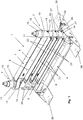
- a rail support device is generally designated by the reference numeral 1 in the figures. It contains as essential elements two mutually opposite spaced apart, with their longitudinal direction vertically extending supports 2 and 3 and a horizontally extending, the distance between the supports 2, 3 in a lower portion of the rail support device 1 bridging basic threshold 4th In the basic threshold a rail support surface 5 is formed, which is displaceable relative to a body 6 of the base threshold 4 in the vertical direction.
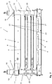
- a clamping bar 7 can be seen in the FIGS. 1 . 2 . 8th and 13 in a distance between the supports 2 and 3 bridging, shown at two supports 2, 3 position is shown.
- This Clamping bar 7 has on a bottom of the base 6 facing a bearing surface 8, which rests in operation of the rail support device 1 with rails arranged thereon on rail heads of an uppermost layer of rails.
- This bearing surface 8 is displaceable relative to a body 9 of the clamping bar 7 in the vertical direction.
- the clamping bar 7 itself is pivotally mounted on the vertical support 2 and also displaceable in the vertical direction with a circular cross-section support 2 embracing, integrally formed on the clamping bar 7 bearing sleeve 10.
- a partially formed in cross-section retaining claw 11 engages in the in FIGS. 1 . 2 . 8th and 13 shown position of the clamping bar 7, the vertical support 3.
- the clamping bar 7 from the in the FIGS. 1 . 2 . 8th and 13 shown position to release the underlying area around the support 2 are given away.
- the bearing sleeve 10 of course remains connected to the support 2. In such a pivoting movement in a in the representation of FIG.
- FIG. 14 A representation of the position in which the clamping bar 7 is pivoted into an open position, is in Fig. 14 shown. In this position, the clamping bar 7 is placed on a formed on a storage support 47 pad 48, so that the bearing sleeve 10 does not permanently bear the weight of the support bar 7 at the end of a one-armed lever.
- the retaining claw 11 is provided with a part-annular recess 19 whose circumferential extent is over 180 °. Via an access opening 20, an abutment portion of the support 3, whose diameter is selected so that it can be performed through the access opening 20, are introduced into the recess 19.
- the threaded sleeve 16 has a reduced in diameter relative to the diameter of the stop collar 17, down over the stop collar 17 projecting cylindrical extension 43 (see Fig. 12 ), which is formed in its diameter corresponding to the diameter of the part-annular recess 19, so that this extension can be introduced into the recess 19 from above.
- cylindrical extension 43 By a corresponding displacement of the screw 16 in the vertical direction downwards by screwing them so this cylindrical extension 43 can be introduced into the recess 19 and then locked due to the over 180 ° encompassing coverage of the recess 19, the retaining claw 11 form-fitting manner.
- two supporting beams 21 are arranged in this embodiment. These each have a bearing surface 22 on its upper side, can be placed on the rails with their rail feet. On their underside, the support beams 21 each have a pressure surface 23, with which they rest on rail heads of a arranged below the respective support beam 21 rail position.
- the support beams 21 are arranged in a similar manner to the support 2 pivotable and vertically displaceable as the clamping bar 7.
- the support beams 21 each have a bearing sleeve 24 which encloses the circular cross-section support 2. At the support 3, the support beams 21 in the in the FIGS. 1 . 2 . 8th and 13 shown position releasably fixed by means of locking elements 25.
- the bearing sleeves 24 of the support beams 21 have on their respective underside a slide track 26 which cooperates with a corresponding, fixed to the support 2 rolling pin 27.
- the pivoted in an open position positions of the support beams 21 are in Fig. 14 to recognize.
- the support beams 21 are stored on supports 48 of the storage support 47.
- This clamping mechanism comprises the vertically displaceable rail support surface 5, an actuator to be explained in more detail below for active vertical displacement of the rail support surface 5 in the direction of the clamping bar 7, the bearing surface 8 and an elastic return means which the bearing surface 8 in the direction of the base threshold 4 in the vertical direction biases.
- the elastic return means consists in this embodiment, in particular FIG. 4 can be seen from a number of longitudinally of the clamping bar 7 successively arranged spring assemblies 28, which exert a correspondingly elastic restoring force on the bearing surface 8.
- These spring assemblies 28 each have a plurality of disc springs 29, which are arranged one above the other to the spring assemblies 28 are connected.
- FIG. 7 is shown in enlarged detail representation of such a spring assembly 28 again in more detail. It is formed by the superimposed and placed over a pin 30 plate springs 29 and placed on the disc springs 29, serving as a stop guide bush 31 which is fixed with a castle nut 32 which is screwed onto the bolt 30 and held in position.
- the individual spring assemblies 28 can be adjusted in the longitudinal direction of the clamping bar 7 with different spring force, so as to form a restoring force profile.
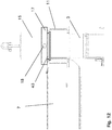
- the rail support surface 5 is by means of a hand pump 44 (see Fig. 13 ) operated hydraulic drive in the vertical direction relative to the body 6 of the basic threshold 4 displaced.
- a hydraulic fluid reservoir and the hand pump 44 are located in a closable with a door 33 device box 34. Via a valve 49, the flow rate of the hydraulic fluid can be regulated.
- the hydraulic fluid is pressurized and arranged via hydraulic lines 45 in the body 6, on the rail support surface 5 acting hydraulic pressure rams 46 supplied.
- the rail support surface 5 is displaced relative to the body 6 of the base threshold 4 in the vertical direction, namely issued upwards in the direction of the clamping bar 7.
- the clamping bar 7 is placed and placed on the rail heads of the top rail layer.
- the positions of the supporting beams 21 and the clamping bar 7 are then such that the lower supporting beam 21 rests on the rail heads of the rails arranged underneath, the upper supporting beam 21 rests on the rail heads of the rails laid on the lower supporting beam 21 and the clamping bar 7 with its bearing surface 8 rests on the rail heads of the laid on the upper support beam 21 rails.
- the thus applied clamping force leads to an elastic deformation of the spring assemblies 28 and a deflection of the bearing surface 8, wherein the spring assemblies 28 apply a corresponding counterforce and thus exert a force acting in the opposite direction clamping force.
- the clamping force is exerted on the recorded in the rail support device 1 rails in two directions, namely once vertically from bottom to top (by means of the actuator upwardly displaced rail support surface 5) and once from top to bottom (by the force exerted by the spring packs 28 on the bearing surface 8 counterforce).
- the application of the clamping force required for the formation of a secure hold of the rails in the rail support device 1 can be accomplished simply and without a special and complex tool, in particular without a crane or large tools.
- the applied clamping force is evenly distributed and very effective by the force in both directions in the vertical direction opposite directions.
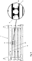
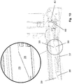
- the bearing surface 8 has an elastic support 35 which elastically deformed during application of the clamping force and so around the rail heads of those rails S sets and fixes against which it rests.
- an elastic support 35 can also be formed on the support beam 21, at least on its pressure surfaces 23. It is also possible to provide the rail support surface 5 and the support surfaces 22 with corresponding elastic supports 35.
- the clamping mechanism of the rail support device 1 may in particular be provided with a blocking means which blocks or locks the rail support surface 5 in a position once set after application of the clamping force by means of the hydraulics and the hand pump 44.
- a blocking means can contribute in particular to the fact that the actuator does not have to remain permanently activated while the rails are held in the rail support device 1 and held clamped.
- the hydraulic system can be relaxed after setting the blocking agent.
- stepped sections 39 are formed, which have equally stepped contact surfaces with the same height gradations and width dimensions.
- the bolt slide is connected via a compression spring 40 which is placed on a shaft 41 formed on the bolt slide 37 and is supported on an abutment, in a in the FIGS. 10 to 11 biased to the left-facing direction, a direction in which the stepped portions 38 fall in a wedge shape.
- the rail support device 1 shown and described in the embodiment shown is typically installed on a rail transport car, to which it is provided with mounting plates 36, which can be bolted to a load-bearing surface of the rail transport vehicle, for example planked with wooden sleepers.
- the rail support device 1 according to the invention is usually arranged with two such devices in a row in a central portion of a rail transport vehicle, the rail transport car is otherwise equipped with conventional and especially not equipped with clamping bar 7 rail support devices.
Description
Die vorliegende Erfindung betrifft eine Schienenauflagevorrichtung mit den Merkmalen des Oberbegriffs des Anspruchs 1.The present invention relates to a rail support device having the features of the preamble of
Derartige Schienenauflagevorrichtungen werden verwendet, um Eisenbahnschienen auf zu Schienentransportzügen zusammengestellten Schienentransportwagen zu transportieren. Transportiert werden dabei insbesondere aus Kurzschienen in einem Schienenschweißwerk bereits vorbereitete bzw. vorgefertigte Langschienen (dies sind Schienenabschnitte von bis zu mehreren hundert Metern Länge), zum Beispiel zu Gleisbaustellen, um dort im Gleis verlegt und an die Schieneninfrastruktur angeschlossen zu werden.Such rail support devices are used to transport railroad tracks on rail transport cars assembled on rail transport trains. In this case, already prepared or prefabricated long rails (these are rail sections of up to several hundred meters in length) are transported, in particular from short rails in a rail welding plant, for example to track construction sites, to be laid there in the track and connected to the rail infrastructure.
Dabei werden die Langschienen typischerweise in mehreren Lagen auf vertikal übereinander angeordnet Tragbalken, die sich quer zu einer Längsrichtung der Schienentransportwagen erstrecken, aufgereiht. Derartige Schienenauflagevorrichtungen sind beispielsweise aus der
Entsprechend ist für dieses Problem eine Lösung erdacht worden, wobei im Rahmen dieser Lösung im Kern auf die oberste Lage der auf den Schienenauflagevorrichtungen angeordneten Schienen ein horizontal verlaufender Klemmbalken aufgesetzt und dieser Klemmbalken mit einem Spannmechanismus in Richtung der Schienenköpfe mit einer Andruckkraft beaufschlagt wird. So sind von der Firma voestalpine AG aus Österreich konzipierte und betriebene Schienentransportwagen bekannt und im Einsatz, die Schienenauflagevorrichtungen aufweisen, in denen in zwei U-förmige profilierte, vertikal verlaufende, mit den Öffnungen der U-Profile aufeinander zu weisende Stützen Auflagebalken für die Auflage von Schienen eingeführt werden können und die mit einem Klemmbalken versehen werden können, der auf die oberste Lage der aufgenommenen Schienen aufgesetzt und mittels Spannschrauben, die auf Gewindestangen, die Öffnungen in den äußeren Enden der Klemmbalken durchragen, verschraubt und gegen die oberste Schienenlage gedrückt werden können. Derartige mit Klemmbalken versehenen Schienentransportauflagen werden bei diesem Konzept nur mit größeren Abständen auf den Schienentransportwagen verteilt angeordnet, davor und dahinter befinden sich Schienentransportauflagen ohne solche Klemmbalken und ohne eine Verklemmung der aufgelegten Schienen, um so ein Ausweichen der Schienen in Kurvenfahrten zu ermöglichen und Beschädigungen der transportierten Schienen durch hohe Biegemomente im Zwischenbereich zu kurzer Klemmabstände zu verhindern.Accordingly, a solution has been devised for this problem, being placed under this solution in the core on the uppermost layer of rails arranged on the rails rails a horizontally extending clamping bar and this clamping bar is acted upon by a clamping mechanism in the direction of the rail heads with a pressing force. Thus, designed and operated by the company voestalpine AG from Austria rail transport cars are known and in use, the rail support devices in which in two U-shaped profiled, vertically extending, with the openings of the U-profiles facing each other support beams for the circulation of Rails can be introduced and can be provided with a clamping bar, which is placed on the top layer of the recorded rails and by means of clamping screws, which project through threaded rods, the openings in the outer ends of the clamping bar, and can be pressed against the top rail layer. Such provided with clamping bar rail transport pads are arranged distributed in this concept only at greater distances on the rail transport car, before and behind are rail transport pads without such clamping beams and no jamming of the laid rails so as to allow evasion of the rails in cornering and damage the transported Rails due to high bending moments in the intermediate area to prevent short clamping distances.
Wenngleich mit diesem vorbekannten System ein Verklemmen der auf der Schienenauflagevorrichtung aufgelegten Schienen erreicht und damit eine Längsverschiebung derselben verhindert werden kann, ist diese Konstruktion dennoch mit Nachteilen behaftet und verbesserungswürdig. Insbesondere ist das Handhaben des Klemmbalken, der zum Be- bzw. Entladen der Schienen stets aus den U-förmigen Führungen der vertikalen Stützen gehoben werden muss, schwierig, erfordert aufgrund des Gewichtes dieses Klemmbalkens den Einsatz eines Kranes, der entsprechend nicht nur an der Beladestelle, sondern vor allem auch an der Entladestelle, bei der es sich häufig um eine außerhalb des Bereichs von größeren Einrichtungen gelegene Baustelle handelt, vorgehalten bzw. bereitgestellt werden muss. Weiterhin ist das Fixieren und Verklemmen des Klemmbalkens mittels der Verschraubungen aufwändig und erfordert wiederum den Einsatz von speziellem Werkzeug, nämlich eines entsprechend dimensionierten Maul- bzw. Ringschlüssels zum Festziehen bzw. Lösen der Mutter. Hierbei können die aufgebrachten Klemmkräfte zudem nur unzulänglich reproduzierbar eingestellt werden, was ebenfalls als nachteilig anzusehen ist.Although with this known system jamming of the rails placed on the rail support device and thus a longitudinal displacement of the same can be prevented, this construction is still subject to disadvantages and should be improved. In particular, the handling is the clamping bar, which must be lifted for loading and unloading the rails always from the U-shaped guides of the vertical supports, difficult, requires the use of a crane due to the weight of this clamping bar, which not only at the loading point, but above all also at the unloading point, which is often a construction site located outside the area of larger facilities, must be provided or provided. Furthermore, the fixing and jamming of the clamping bar by means of the screw connections is complex and in turn requires the use of special tools, namely a correspondingly sized mouth or ring wrench for tightening or loosening the nut. In this case, the applied clamping forces can also be set only insufficiently reproducible, which is also considered to be disadvantageous.
Der Klemmbalken bei der bekannten, oben beschriebene Lösung weist auf seiner zur Auflage auf die Schienenköpfe der obersten Lage der in der Schienenauflagevorrichtung aufgenommenen Schienen zugewandten Seite ein Holzbrett auf, mit dem er auf den Schienenköpfen aufliegt. Dabei kann beobachtet werden, dass einerseits durch aufgrund von Fertigungstoleranzen gegebenen unterschiedlichen Abmessungen der Schienen (insbesondere in der Schienenhöhe, gemessen vom Niveau des Schienenfußes bis zum Niveau des Schienenkopfes), andererseits durch eine ungenaue Formgebung des Holzbretts auf die nebeneinander in der obersten Schicht der Schienen in der Schienenauflagevorrichtung aufgenommenen Schienen unterschiedliche Andruckkräfte ausgeübt werden. Hierbei kann es sogar vorkommen, dass trotz eines Verspannen des Klemmbalkens gegen die oberste Schienenlage einzelne Schienen nur einen geringen oder sogar gar keinen nennenswerten Andruck erfahren, also auch nicht, wie angestrebt, sicher durch den Klemmbalken fixiert werden. Auch hierin besteht also ein Verbesserungsbedarf.The clamping bar in the known, above-described solution has on its side facing the support on the rail heads of the uppermost layer of the recorded in the rail support device rails a wooden board, with which it rests on the rail heads. It can be observed that on the one hand by given due to manufacturing tolerances different dimensions of the rails (especially in the rail height, measured from the level of the rail foot to the level of the rail head), on the other hand by inaccurate shaping of the wooden board on the side by side in the uppermost layer of the rails In the rail support device recorded rails different pressure forces are exercised. In this case, it may even happen that, despite a distortion of the clamping bar against the top rail position individual rails experience little or even no significant pressure, so not, as desired, be securely fixed by the clamping bar. Here, too, there is a need for improvement.
Eine weitere Schienenauflagevorrichtung mit Stützen (102,104), Grundschwelle (2a), Klemmbalken (26), Spannmechanismus (4), Lagerfläche (58) des Klemmbalkens (26) die relativ zu einem Korpus des Klemmbalkens (26) in vertikaler Richtung verlagerbar, und mittels Stellantrieb (70) aktiv in Richtung Schienenauflagefläche zustellbar ist, ist aus der
Diese Aufgabe wird erfindungsgemäß gelöst durch eine Schienenauflagevorrichtung mit den Merkmalen des Anspruchs 1. Vorteilhafte Weiterbildungen einer solchen erfindungsgemäßen Schienenauflagevorrichtung sind in den abhängigen Ansprüchen 2 bis 14 angegeben und näher bezeichnet.This object is achieved by a rail support device with the features of
Gemäß der Erfindung hat die neuartige Schienenauflagevorrichtung also - dies zunächst in Übereinstimmung mit dem Stand der Technik - zwei einander gegenüberstehende, einen Auflagebereich seitlich begrenzende vertikale Stützen, eine in einem vertikal unteren Bereich zwischen den Stützen verlaufende Grundschwelle, die auf einer Oberseite eine Schienenauflagefläche für das Abstellen von Schienen definiert, einen oberhalb der Grundschwelle angeordneten, an den Stützen festlegbaren, horizontal verlaufenden Klemmbalken, der auf einer Unterseite einer Lagerfläche aufweist zur Anlage an Schienenköpfe einer Lage von auf der Schienenauflagevorrichtung abgelegten Schienen, und einen Spannmechanismus zum Aufbringen einer vertikal zwischen der Grundschwelle und dem Klemmbalken wirkenden Klemmkraft.According to the invention, the novel rail support device thus - this first in accordance with the prior art - two opposing, a support area laterally bounding vertical supports, extending in a vertically lower portion between the supports basic threshold, on a top a rail support surface for the Shutdown of rails defines a horizontal bar arranged above the base, which is mountable on a bottom surface of a bearing surface for engaging rail heads of a layer of rails deposited on the rail support device, and a tensioning mechanism for applying vertically between the base rail and the clamping bar acting clamping force.
Die neuartige Schienenauflagevorrichtung unterscheidet sich nun vom bekannten Stand der Technik dadurch, dass die Schienenauflagefläche relativ zu einem Korpus der Grundschwelle in vertikaler Richtung verlagerbar ist und dass die Lagerfläche relativ zu einem Korpus des Klemmbalkens in vertikaler Richtung verlagerbar ist, wobei eine der genannten Flächen, also die Schienenauflagefläche oder die Lagerfläche, mittels eines Antriebes aktiv in Richtung der jeweils anderen Fläche, also der Lagerfläche bzw. der Schienenauflagefläche, zustellbar ist und wobei die jeweils andere Fläche, also die Lagerfläche bzw. die Schienenauflagefläche, über ein elastisches Rückstellmittel in Richtung der einen mittels des Antriebes aktiv in Richtung der anderen Fläche zustellbaren Fläche, also der Schienenauflagefläche bzw. der Lagerfläche, vorgespannt ist.The novel rail support device now differs from the known prior art in that the rail support surface is displaceable relative to a body of the basic threshold in the vertical direction and that the bearing surface is displaceable relative to a body of the clamping bar in the vertical direction, wherein one of said surfaces, ie the rail support surface or the bearing surface, by means of a drive active in the direction of the other surface, ie the bearing surface or the rail support surface, can be fed and wherein the other surface, ie the bearing surface or the rail support surface, via an elastic return means in the direction of the one by means of the drive actively in the direction of the other surface deliverable surface, ie the rail support surface or the bearing surface, is biased.
Durch diese erfindungsgemäße Neuerung und konstruktive Umgestaltung gegenüber dem bekannten Stand der Technik werden verschiedene Vorteile realisiert:
- So kann ein entsprechender Antrieb insbesondere so ausgestaltet werden, dass er ohne ein mitzuführendes Werkzeug betätigt werden kann. Desweiteren wird durch die Kombination aus einem aktiven Zustellen einer der Flächen Lagerfläche bzw. Schienenauflagefläche und das passive Auslösen einer Gegenkraft durch das elastische Rückstellmittel, welches die andere Fläche, Lagerfläche bzw. Schienenauflagefläche in einer Klemmrichtung vorspannt, ein vergleichmäßigter und verbessert wirkender Eintrag der Klemmkraft erzielt. Dabei kann der Antrieb vorteilhafterweise auch derart gestaltet sein, dass er eine reproduzierbare Aufbringung einer wählbaren Klemmkraft erlaubt, kann beispielsweise mit einer eine die Klemmkraft repräsentierenden Stellgröße anzeigenden und oder einhaltenden Einrichtung versehen sein, zum Beispiel im Hinblick auf die Stromaufnahme eines durch einen Elektromotor angetrieben Stellantriebes oder durch den Druck eines hydraulisch oder pneumatisch betätigten Stellantriebes.
- Thus, a corresponding drive can in particular be designed such that it can be actuated without a tool to be guided. Furthermore, by the combination of an active infeed one of the surfaces bearing surface or rail support surface and the passive release of a counterforce by the elastic return means which biases the other surface, bearing surface or rail support surface in a clamping direction, a more equal and improved acting entry of the clamping force achieved , In this case, the drive can advantageously also be designed such that it allows a reproducible application of a selectable clamping force, for example, be provided with a the clamping force representing a control variable indicating and / or maintaining device, for example with regard to the current consumption of an actuator driven by an electric motor or by the pressure of a hydraulically or pneumatically actuated actuator.
Mit Vorteil ist der Antrieb dabei ein hydraulisch betätigter Antrieb. Ein hydraulisch betätigter Antrieb hat den Vorteil, dass mit ihm große Kräfte erzeugt und übertragen werden können. Zugleich kann er, was gemäß einer weiteren vorteilhaften Weiterbildung der Erfindung vorgesehen ist, als handbetätigter Antrieb ausgestaltet sein, wenn dieser beispielsweise eine Hydraulikhandpumpe aufweist. Diese Form der Gestaltung des Antriebes erlaubt eine Ausbildung ohne das Erfordernis der Zuführung einer Energieversorgung von außerhalb, beispielsweise einer Stromversorgung, so dass die erfindungsgemäße Schienenauflagevorrichtung letztlich als autarke Einheit ausgestaltet und gebildet werden kann.Advantageously, the drive is a hydraulically operated drive. A hydraulically actuated drive has the advantage that large forces can be generated and transmitted with it. At the same time, what is provided according to a further advantageous development of the invention can be designed as a manually operated drive, if it has, for example, a hydraulic hand pump. This form of design of the drive allows training without the need of supplying a power supply from outside, such as a power supply, so that the rail support device according to the invention can ultimately be designed and formed as a self-sufficient unit.
Das elastische Rückstellmittel kann mit Vorteil Federpakete umfassen, die zwischen der mit dem elastischen Rückstellmittel versehenen Fläche, also der Lagerfläche bzw. der Schienenauflagefläche, und einem Gehäuse, in dem diese Fläche in vertikaler Richtung verlagerbar ist, angeordnet sind. Deartige Federpakete können konstruktiv vergleichsweise einfach realisiert sein, sie können beispielsweise als Tellerfederpakete gebildet sein. Durch die Ausgestaltung mit mehreren derartigen Federpaketen, die insbesondere in dem Element, in dem sie verbaut sind (Grundschwelle oder Klemmbalken) in der jeweiligen Längsrichtung dieses Elementes, also in der Richtung, in der sich die vertikalen Stützen einander gegenüberliegen, hintereinander an verschiedenen Positionen angeordnet sein können, kann auch eine sehr gezielte Verteilung der Klemmkraft erreicht werden. Durch eine individuelle Gestaltung und Auswahl der Federkraft der einzelnen Federpakete kann dabei sogar auf ein Klemmkraftprofil Einfluss genommen werden, um dadurch entsprechende Anpassungen der erforderlichen Klemmkraft an die im Hinblick auf die horizontale und seitliche Positionierung der Schienen erforderliche Position vornehmen zu können.The elastic return means may advantageously comprise spring packs which are arranged between the surface provided with the elastic return means, that is to say the bearing surface or the rail support surface, and a housing in which this surface can be displaced in the vertical direction. Deartige spring packages can be structurally comparatively easy to implement, they can be formed, for example, as a cup spring packages. Due to the design with several such spring assemblies, in particular in the element in which they are installed (basic threshold or clamping bar) in the respective longitudinal direction of this element, ie in the direction in which the vertical supports face each other, can be arranged one behind the other at different positions, a very targeted distribution of the clamping force can be achieved. By an individual design and selection of the spring force of the individual spring assemblies can even be influenced on a clamping force profile to thereby make appropriate adjustments to the required clamping force to the required with regard to the horizontal and lateral positioning of the rails position.
Gemäß einer weiteren vorteilhaften Weiterbildung der Erfindung kann in der erfindungsgemäßen Schienenauflagevorrichtung in vertikaler Richtung zwischen der Grundschwelle und dem Klemmbalken wenigstens ein an den Stützen in vertikaler Richtung verlagerbar festlegbarer, in horizontaler Richtung verlaufender Tragbalken vorgesehen sein, der auf einer Unterseite eine Andruckfläche zum Auflegen auf Schienenköpfe von unterhalb des Tragbalkens angeordneten Schienen und auf einer Oberseite eine Auflagefläche für das Abstellen von auf dem Tragbalken aufgelagerten Schienen aufweist. Ein solcher Tragbalken ermöglicht die Aufnahme von Schienen in der Schienenauflagevorrichtung in einer weiteren vertikalen Stapelebene, so dass eine entsprechend größere Anzahl von Schienen auf der Schienenauflagevorrichtung abgelegt werden kann. Dabei ist es wichtig, dass der Tragbalken an den Stützen in vertikaler Richtung verlagerbar festlegbar ist. Denn so kann, wenn mittels des die vertikal verlagerbaren Flächen Schienenauflagefläche und Lagerfläche sowie den Stellantrieb umfassenden Spannmechanismus zwischen dem Klemmbalken und der Grundschwelle eine Klemmkraft aufgebracht wird, diese auf die übereinander angeordneten Ebenen der aufgelegten Schienen aufgebracht und entsprechend vertikal auf und über Tragbalken übertragen werden. Insbesondere können dabei auch mehr als ein derartiger Tragbalken, beispielsweise können zwei solche Tragbalken vorgesehen sein, so dass noch weitere vertikal übereinander angeordnete Lagen von Schienen zum Transport aufgestapelt werden können, bei zwei Tragbalken also entsprechend drei Schienenlagen. Zu betonen ist, dass auch bei mehreren derartigen Tragbalken entscheidend ist, dass sämtliche Tragbalken vertikal verlagerbar an den Stützen festgelegt sind, so dass die aufgebrachte Klemmkraft auf alle Lagen der vertikalen übereinander angeordneten Schienen wirken kann. Die Tragbalken klemmen dabei jeweils mit der Andruckfläche die untere Lage von Schienen durch Aufbringen der Klemmkraft bzw. durch weiterleiten der Klemmkraft auf die Schienenköpfe dieser Lage und mit der Auflagefläche die obere Lage Schienen von der Schienenfußseite her.According to a further advantageous embodiment of the invention may be provided in the rail support device according to the invention in the vertical direction between the base and the clamping bar at least one displaceable on the supports in the vertical direction festlegbarer, extending in the horizontal direction support beams on a bottom a pressure surface for placement on rail heads From below the support beam arranged rails and on a top surface has a bearing surface for the parking of rails mounted on the support beam. Such a support beam allows the inclusion of rails in the rail support device in a further vertical stack level, so that a correspondingly larger number of rails can be stored on the rail support device. It is important that the support beam on the supports in the vertical direction can be fixed displaced. Because so if, by means of the vertically displaceable surfaces rail support surface and bearing actuator and the actuator comprehensive clamping mechanism between the clamping bar and the base threshold, a clamping force is applied, applied to the superimposed planes of the applied rails and transmitted vertically on and on supporting beams. In particular, more than one such support beam, for example, two such support beams may be provided so that even more vertically stacked layers of rails can be stacked for transport, in two support beams so according to three rail layers. It should be emphasized that, even with a plurality of such support beams, it is crucial that all support beams are fixed vertically displaceable on the supports, so that the applied clamping force can act on all layers of the vertical rails arranged one above the other. Clamp the stringers in each case with the pressure surface, the lower layer of rails by applying the clamping force or by forwarding the clamping force on the rail heads this position and with the support surface, the upper layer rails from the rail foot side.
Mit Vorteil kann der eine bzw. können die mehreren Tragbalken an einer der Stützen um deren Vertikalachse verschwenkbar festgelegt sein. Eine solche Konstruktion erlaubt es, die Tragbalken, die in dieser Ausgestaltung auch als "Drehschwellen" bezeichnet werden können, nicht etwa insgesamt von den vertikal verlaufenden Stützen abheben zu müssen, um Schienen auf die Schienenauflagevorrichtung auf- oder von dieser abzuladen. Vielmehr können die Tragbalken einfach um die vertikaler Achse der Stütze, an der sie verschwenkbar festgelegt sind, verschwenkt und so aus der Überdeckung mit den Schienen bzw. mit der für die Auflage der Schienen vorgesehenen Fläche gebracht werden, so dass die Schienenauflagevorrichtung be- bzw. entladen werden kann. Dabei können an der Stütze, an der der Tragbalken um deren vertikale Achse verschwenkbar und an der Stütze in vertikaler Richtung verlagerbar festgelegt ist, Tragbalkenhubmittel vorgesehen sein, die bei einer Schwenkbewegung des Tragbalkens um die Längsachse der Stütze, an der er verschwenkbar festgelegt ist, eine vertikale Verlagerung des Tragbalkens bewirken. Auf diese Weise wird beim Verschwenken des Tragbalkens zugleich ein Abheben von der Schienenlage, auf der dieser mit der Andruckfläche aufliegt, bewirkt, so dass dieses Abheben nicht durch manuelles Anheben des Tragbalkens zu bewerkstelligen ist, sondern zugleich mit der Schwenkbewegung erfolgt. Hierbei kann beispielsweise eine Kulissenführung (oder ein Drehlager mit eine solchen Kulissenführung) gebildet sein, wie Sie in der
Desweiteren kann, wenn die Schienenauflagevorrichtung nach der Erfindung wenigstens einen Tragbalken vorsieht, die Andruckfläche und/oder kann die Auflagefläche dieses Tragbalkens mit einer elastischen Auflage versehen sein. Eine solche elastische Auflage kann beispielsweise eine Hartgummimatte sein, die auf die entsprechende Fläche aufgebracht oder in diese eingebracht ist. Eine solche elastische Auflage kann mit Vorteil eine weitergehende und noch verbesserte Fixierung der an die jeweilige Fläche angelegten Schienen bewirken, indem durch die elastische Verformung der Auflage die Andruckfläche bzw. die Auflagefläche aufgrund der mittels des Stellantriebes aufgebrachten Klemmkraft sich verformt und damit etwaige infolge von Toleranzen in den Schienenabmessungen auftretende Höhenunterschiede ausgeglichen werden, so dass sichergestellt ist, dass alle Schienen mit einer entsprechenden Klemmwirkung erfasst werden.Furthermore, if the rail support device according to the invention provides at least one support beam, the pressure surface and / or the bearing surface of this support beam can be provided with an elastic support. Such an elastic support may for example be a hard rubber mat, which is applied to the corresponding surface or introduced into this. Such elastic pad can advantageously a more advanced and even improved Fixing cause the applied to the respective surface rails by deformed by the elastic deformation of the support the pressure surface or the bearing surface due to the force applied by the actuator clamping force and thus any occurring due to tolerances in the rail dimensions height differences are compensated, so that is ensured in that all rails are detected with a corresponding clamping effect.
Mit Vorteil kann gemäß einer Weiterbildung der Erfindung der Klemmbalken an einer der Stützen um deren Längsachse verschwenkbar festgelegt sein. Ähnlich wie vorstehend im Zusammenhang mit den optional vorzusehenden Tragbalken beschrieben, ergibt auch im Zusammenhang mit dem Klemmbalken eine derartige Lösung den Vorteil, dass der Klemmbalken nicht insgesamt von den vertikalen Stützen abgehoben werden muss. Vielmehr genügt es, den Klemmbalken mit geringerem Kraftaufwand zu verschwenken und so darunter angeordnete Schienen bzw. eine Fläche für die Auflage von Schienen freizugeben. Mit Vorteil kann dabei vorgesehen sein, dass der Klemmbalken an der Stütze nicht allein um deren Vertikalachse verschwenkbar festgelegt ist, sondern weiterhin auch in vertikaler Richtung verlagerbar. So kann der Klemmbalken für die Ausbildung der Andruckkraft bzw. Klemmkraft entsprechend in der Höhe verstellt werden. Zugleich kann der Klemmbalken beim Verschwenken auch von der Schienenlage, auf der er aufliegt, abgehoben werden. Dieses Abheben kann, ähnlich wie vorstehend im Hinblick auf die optionalen Tragbalken beschrieben, über Klemmbalkenhubmittel unterstützt werden, welche bei einer Schwenkbewegung des Klemmbalkens um die Vertikalachse der Stütze, an der der Klemmbalken verschwenkbar festgelegt ist, eine Vertikalverlagerung des Klemmbalkens bewirken. Auch hier kann mit Vorteil eine Kulissenführung gewählt werden, wie diese beispielsweise in der
Weitere Vorteile bietet eine Weiterbildung der Schienenauflagevorrichtung, bei der die Schienenauflagefläche der Grundschwelle und/oder die Lagerfläche des Klemmbalkens mit einer elastischen Auflage versehen ist/sind. Eine solche elastische Auflage kann wiederum auf die Lagerfläche bzw. auf die Schienenauflagefläche aufgebracht oder in die betreffende Fläche eingelassen sein. Sie kann wiederum zum Beispiel die Form einer Hartgummimatte aufweisen. Eine solche elastische Auflage ergibt in oben bereits anhand der analogen, für den optional vorzusehenden Tragbalken als Ausgestaltungsoption möglichen elastischen Auflage beschriebenen Weise den Vorteil einer für alle Schienen gesicherten Klemmwirkung durch Ausgleich von zum Beispiel durch Fertigungstoleranzen gegebenen Höhenunterschiede innerhalb von Schienenlagen.Further advantages are provided by a further development of the rail support device, in which the rail support surface of the base sleeper and / or the bearing surface of the clamping beam is / are provided with an elastic support. Such an elastic support can in turn be applied to the bearing surface or on the rail support surface or embedded in the surface in question. She can turn For example, have the shape of a hard rubber mat. Such an elastic support results in the manner already described above with reference to the analog, for the optionally provided support beam as a design option possible elastic support the advantage of a secured rail for all clamping action by compensating given for example by manufacturing tolerances height differences within rail layers.
In einer weiteren Weiterbildung ist vorgesehen, dass die Schienenauflagevorrichtung der Erfindung ein mechanisches Blockiermittel aufweisen kann, welches dem lösbaren Blockieren der mit dem Stellantrieb zugestellten Fläche (also der Schienenauflagefläche bzw. der Lagerfläche) in einer mittels des Stellantriebs eingestellten vertikalen Position bewirkt. Ein solches mechanisches Blockiermittel kann mit Vorteil dann, wenn mittels des Stellantriebs die erforderliche oder gewünschte Klemmkraft aufgebracht ist, die mit dem Stellantrieb aktiv bewegte Fläche in ihrer Position blockieren bzw. festlegen, so dass der Stellantrieb abgeschaltet werden kann und nicht während einer Nutzungsdauer, zum Beispiel während einer Transportfahrt zum Transportieren von Schienen, fortwährend zum Aufbringen bzw. zum Aufrechterhalten der Kernkraft aktiv gehalten werden muss. Soll dann die Klemmwirkung aufgehoben werden, um auf der Schienenauflagevorrichtung angeordnete und darin verklemmte Schienen zu lösen, wird das Blockiermittel gelöst und aus einer Blockierstellung in eine Freigabeposition verbracht. Zu Lösen des Blockiermittels kann beispielsweise der Stellantrieb aktiviert werden, um das Blockiermittel durch Aufbringen einer Klemmkraft zu Entlasten und ein Verlagern derselben in die Freigabeposition zu ermöglichen. Der Stellantrieb ist durch ein solches Blockiermittel also gleichermaßen mit einer Selbsthemmung versehen, die die einmal eingenommene Position des mit dem Stellantrieb positionierten Elements auch dann hält, wenn der Stellantrieb kraftlos geschaltet wird.In a further development it is provided that the rail support device of the invention may have a mechanical locking means, which causes the releasable blocking of the delivered with the actuator surface (ie the rail support surface or the bearing surface) in a set by means of the actuator vertical position. Such a mechanical locking means can advantageously when the required or desired clamping force is applied by means of the actuator, block or set the actively moving surface with the actuator in position, so that the actuator can be switched off and not during a period of use, for Example during a transport journey to transport rails, must be kept active to apply or maintain the nuclear power active. If the clamping action is then to be canceled in order to release rails arranged on the rail support device and clamped therein, the blocking means is released and moved from a blocking position into a release position. To release the blocking agent, for example, the actuator can be activated to relieve the blocking agent by applying a clamping force and to allow a displacement thereof in the release position. The actuator is thus equally provided by such a blocking means with a self-locking, which also holds the once occupied position of the positioned with the actuator element when the actuator is switched powerless.
Die erfindungsgemäße Schienenauflagevorrichtung kann in einer weiteren vorteilhaften konstruktiven Weiterbildung, in der der Klemmbalken an den vertikalen Stützen in vertikaler Richtung verlagerbar angeordnet ist, an den vertikalen Stützen Widerlagerelemente aufweisen, die oberhalb des Klemmbalkens angeordnet sind und die in Längsrichtung der Stützen höhenverstellbar sind. Diese Art der Ausgestaltung erlaubt eine Einstellung der vertikalen Höhenposition des Klemmbalkens zur Anpassung an die Stapelhöhe der in der Schienenauflagevorrichtung aufgenommenen Schienen. Derartige Widerlagerelemente können zum Beispiel durch, vorteilhalfterweise mit Kontermuttern gesicherte, Schraubhülse gebildet sein, die auf ihren dem Klemmbalken zugewandten Fläche eine entsprechende Widerlagerfläche ausbilden. Dabei können über die Widerlagerflächen in Richtung des Klemmbalkens vorstehend zum Beispiel zylinderförmige Halteabschnitte gebildet sein, die einen größeren Durchmesser aufweisen als ein Anschlagabschnitt der Stützen, so dass der Klemmbalken mit einem offenen, ringförmigen Aufnahmebereich, der eine mehr als 180° umfassende Umfangsumschließung und eine Öffnungsweite aufweist, die größer ist als der Durchmesser des Anlageabschnitts der Stützen in dem Anlageabschnitt über die Stütze gelegt und dann durch vertikales Zustellen eines solchen Widerlagerelements in einer Weise, dass der zylinderförmige Halteabschnitt in den ringförmigen Aufnahmebereich hinein gelangt, formschlüssig verriegelt werden kann.The rail support device according to the invention can in a further advantageous constructive development, in which the clamping bar is arranged to be displaceable on the vertical supports in the vertical direction, on the vertical supports abutment elements, which are arranged above the clamping bar are and which are adjustable in height in the longitudinal direction of the supports. This type of configuration allows adjustment of the vertical height position of the clamping bar to adapt to the stacking height of the recorded in the rail support device rails. Such abutment elements can be formed, for example, by an advantageous halbhalfweise secured with lock nuts, screw sleeve, which form a corresponding abutment surface on their the clamping bar surface facing. In this case, over the abutment surfaces in the direction of the clamping bar above, for example, cylindrical holding portions may be formed, which have a larger diameter than a stop portion of the supports, so that the clamping bar with an open, annular receiving area having a more than 180 ° circumferential enclosure and an opening width which is larger than the diameter of the abutment portion of the supports in the abutment portion placed over the support and then by positively advancing such an abutment member in a manner that the cylindrical holding portion enters into the annular receiving area, can be positively locked.
Mit Vorteil kann bei der erfindungsgemäßen Schienenauflagevorrichtung die Schienenauflagefläche in der Grundschwelle diejenige sein, die mittels des Antriebs aktiv in Richtung der Lagerfläche zustellbar ist, wohingegen die Lagerfläche in dem Klemmbalken über das elastische Rückstellmittel in Richtung der Schieneauflagefläche vorgespannt ist. Eine solche Lösung hat sich deshalb als vorteilhaft erwiesen, da der Klemmbalken stets für ein Be- bzw. ein Entladen der Schienenauflagevorrichtung bewegt und verlagert werden muss, wohingegen die Grundschwelle fortwährend ortsfest angeordnet ist. In ein ortsfest angeordnetes Element lässt sich der Stellantrieb leichter und mit weniger konstruktiven Aufwand integrieren.Advantageously, in the rail support device according to the invention, the rail support surface in the basic threshold be that which can be actively fed by means of the drive in the direction of the bearing surface, whereas the bearing surface is biased in the clamping bar via the elastic return means in the direction of the rail support surface. Such a solution has therefore proved to be advantageous, since the clamping bar always has to be moved and relocated for loading or unloading of the rail support device, whereas the basic threshold is constantly stationary. In a stationary arranged element, the actuator can be integrated easily and with less design effort.
Weitere Vorteile und Merkmale der Erfindung ergeben sich aus der nachfolgenden Beschreibung eines Ausführungsbeispiels anhand der beigefügten Figuren. Dabei zeigen:
- Fig. 1
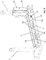
- eine dreidimensionale Ansicht eines Ausführungsbeispiels einer erfindungsgemäßen Schienenauflagevorrichtung mit ihren wesentlichen Elementen;
- Fig. 2
- eine Ansicht der in
Fig. 1 dargestellten Schienenauflagevorrichtung von vorn; - Fig. 3
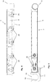
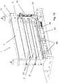
- eine dreidimensionale Ansicht der Anordnung der Elemente Grundschwelle und Stützen der Schienenauflagevorrichtung nach
Fig. 1 mit weiteren Anbauteilen aus einer der Blickrichtung derFign. 1 und2 entgegengesetzten Blickrichtung auf die Schienenauflagevorrichtung; - Fig. 4
- eine Seitenansicht des Klemmbalkens der Schienenauflagevorrichtung gemäß
Fig. 1 mit weggeschnittener Seitenwand; - Fig. 5
- eine teilweise geschnittene Aufsicht auf den Klemmbalken;
- Fig. 6
- eine teilweise geschnittene Seitenansicht des Klemmbalkens;
- Fig. 7
- eine vergrößerte Darstellung des in
Fig. 6 mit A bezeichneten Details; - Fig. 8
- eine der
Fig. 2 vergleichbare Ansicht der Schienenauflagevorrichtung mit gesonderter Vergrößerter Darstellung eines Ausschnitts inklusive Darstellung zweiter darin angeordneter Schienen zur Verdeutlichung der Wirkung einer auf einer Unterseite des Klemmbalkens angeordneten elastischen Auflage; - Fig. 9
- eine Darstellung ähnlich der in
Fig. 3 , jedoch ohne eine Abdeckung an dem Korpus der Grundschelle, so dass innenliegende, einer Verriegelung dienende Elemente sichtbar werden; - Fig. 10
- vergrößert einen Ausschnitt der inneren Struktur in dem Korpus der Grundschwelle mit dem Verriegelungsmechanismus, inklusive einer Ausschnittsvergrößerung eines Details dieser Darstellung;
- Fig. 11
- in einem gegenüber der
Fig. 10 nochmals vergrößerten Ausschnitt eine Darstellung weiterer Details aus dem Inneren des Korpus der Grundschwelle; - Fig. 12
- eine Detaildarstellung des Zusammenwirkens der Schraubhülse mit der Halteklaue des Klemmbalkens für eine formschlüssige Fixierung des Klemmbalkens an der Stützstrebe, an der die Halteklaue anliegt;
- Fig. 13
- eine Darstellung mit Ansicht auf das Innere in dem Korpus der Grundschwelle zur Darstellung des hydraulischen Spannmechanismus und seines Stellantriebes und
- Fig. 14
- eine Darstellung der Schienenauflagevorrichtung mit in Offenstellung verschwenkten Trag- und Klemmbalken.
- Fig. 1
- a three-dimensional view of an embodiment of a rail support device according to the invention with its essential elements;
- Fig. 2
- a view of in
Fig. 1 shown rail support device from the front; - Fig. 3
- a three-dimensional view of the arrangement of the elements basic threshold and supports the rail support device according to
Fig. 1 with additional attachments from one of the line of sightFIGS. 1 and2 opposite viewing direction on the rail support device; - Fig. 4
- a side view of the clamping bar of the rail support device according to
Fig. 1 with cut sidewall; - Fig. 5
- a partially cut view of the clamping bar;
- Fig. 6
- a partially sectioned side view of the clamping bar;
- Fig. 7
- an enlarged view of the in
Fig. 6 details marked with A; - Fig. 8
- one of the
Fig. 2 comparable view of the rail support device with a separate enlarged view of a section including representation of second rails arranged therein to illustrate the effect of an arranged on an underside of the clamping bar elastic support; - Fig. 9
- a representation similar to the one in
Fig. 3 but without a cover on the body of the base clamp, so that internal locking elements are visible; - Fig. 10
- enlarges a section of the inner structure in the body of the basic threshold with the locking mechanism, including an enlarged detail of a detail of this representation;
- Fig. 11
- in one opposite
Fig. 10 again enlarged detail a representation of further details from the inside of the body of the basic threshold; - Fig. 12
- a detailed view of the interaction of the threaded sleeve with the retaining claw of the clamping bar for a positive fixation of the clamping bar on the support strut against which the retaining claw;
- Fig. 13
- an illustration with a view of the interior in the body of the basic threshold for illustrating the hydraulic tensioning mechanism and its actuator and
- Fig. 14
- an illustration of the rail support device with pivoted in the open position supporting and clamping bar.
In den Figuren ist ein Ausführungsbeispiel für eine erfindungsgemäß gestaltete Schienenauflagevorrichtung in verschiedenen Ansichten gezeigt und dargestellt. Dieses Ausführungsbeispiel wird nachfolgend unter Bezugnahme auf die Figuren beschrieben. Dabei ist hervorzuheben, dass die Figuren keine vollständigen Konstruktionszeichnungen darstellen, vielmehr als weitgehend schematische Abbildungen der für die Erfindung wesentlichen Elemente und weiterer vorteilhafter Ausgestaltungen und Merkmale darstellen.In the figures, an embodiment of an inventively designed rail support device is shown and shown in different views. This embodiment will be described below with reference to the figures. It should be emphasized that the figures do not represent complete design drawings, but rather represent largely schematic illustrations of the elements essential to the invention and further advantageous embodiments and features.
Eine erfindungsgemäße Schienenauflagevorrichtung ist in den Figuren ganz allgemein mit dem Bezugszeichen 1 bezeichnet. Sie enthält als wesentliche Elemente zwei einander gegenüberliegende mit Abstand zueinander angeordnete, mit ihrer Längsrichtung vertikal verlaufende Stützen 2 und 3 sowie eine horizontal verlaufende, den Abstand zwischen den Stützen 2, 3 in einem unteren Abschnitt der Schienenauflagevorrichtung 1 überbrückende Grundschwelle 4. In der Grundschwelle 4 ist eine Schienenauflagefläche 5 gebildet, die relativ zu einem Korpus 6 der Grundschwelle 4 in vertikaler Richtung verlagerbar ist.A rail support device according to the invention is generally designated by the
Vertikal oberhalb der Grundschwelle 6 ist ein Klemmbalken 7 zu erkennen, der in den
Der Klemmbalken 7 selbst ist an der vertikalen Stütze 2 verschwenkbar und auch in vertikaler Richtung verlagerbar festgelegt mit einer die im Querschnitt kreisförmige Stütze 2 umgreifenden, an dem Klemmbalken 7 angeformten Lagerhülse 10. Mit einer im Querschnitt teilringförmig gebildeten Halteklaue 11 umgreift in der in den
An den vertikalen Stützen 2 und 3 sind oberhalb des Klemmbalkens 7 in vertikaler Richtung verlagerbare Widerlagerelemente in Form von Schraubhülsen 15 und 16 mit daran jeweils ausgebildeten, ringförmig überstehenden Anschlagkragen 17 angeordnet. In den Anschlagkragen 17 sind umfangsseitig Öffnungen 18 eingebracht, die als Werkzeugansatz dienen, um ein Werkzeug zum Verschrauben der Schraubhülsen 15 bzw. 16 ansetzen zu können. Wie insbesondere
In dem vertikalen Bereich zwischen der Grundschwelle 4 und dem Klemmbalken 7 sind in dieser Ausführungsform zwei Tragbalken 21 angeordnet. Diese weisen jeweils eine Auflagefläche 22 auf ihrer Oberseite auf, auf die Schienen mit ihren Schienenfüßen aufgelegt werden können. Auf ihrer Unterseite weisen die Tragbalken 21 jeweils eine Andruckfläche 23 auf, mit der sie auf Schienenköpfen einer unterhalb des jeweiligen Tragbalkens 21 angeordneten Schienenlage aufliegen. Die Tragbalken 21 sind in ähnlicher Weise an der Stütze 2 verschwenkbar und vertikal verlagerbar angeordnet wie der Klemmbalken 7. Auch die Tragbalken 21 weisen jeweils eine Lagerhülse 24 auf, die die im Querschnitt kreisförmige Stütze 2 umschließt. An der Stütze 3 werden die Tragbalken 21 in der in den
Zum sicheren Verklemmen von in der Schienenauflagevorrichtung 1 aufgenommenen Schienen wird nun mittels eines Spannmechanismus eine vertikal wirkende Klemmkraft auf die Schienen aufgebracht. Dieser Spannmechanismus umfasst dabei die vertikal verlagerbare Schienenauflagefläche 5, einen nachfolgend noch näher zu erläuternden Stellantrieb zum aktiven vertikalen Verlagern der Schienenauflagefläche 5 in Richtung des Klemmbalkens 7, die Lagerfläche 8 sowie ein elastisches Rückstellmittel, welches die Lagerfläche 8 in Richtung der Grundschwelle 4 in vertikaler Richtung vorspannt.For secure clamping of recorded in the
Das elastische Rückstellmittel besteht in diesem Ausführungsbeispiel, wie insbesondere
Die Schienenauflagefläche 5 ist mittels eines mit einer Handpumpe 44 (vergleiche
Durch Betätigen der Handpumpe 44 wird die Hydraulikflüssigkeit mit Druck beaufschlagt und über Hydraulikleitungen 45 in dem Korpus 6 angeordneten, auf die Schienenauflagefläche 5 wirkenden Hydraulikdruckstempeln 46 zugeführt. Über die Hydraulikdruckstempel 46 wird die Schienenauflagefläche 5 relativ zu dem Korpus 6 der Grundschwelle 4 in vertikaler Richtung verlagert, nämlich nach oben in Richtung des Klemmbalkens 7 ausgestellt.By pressing the
Wenn nun die Schienenauflagevorrichtung 1 vollständig mit den aufzunehmenden Schienen bestückt ist, d.h. Schienen sowohl auf der Schienenauflagefläche 5 der Grundschwelle 4 als auch auf den Auflageflächen 22 der Tragbalken 21 aufgenommen sind, wird der Klemmbalken 7 aufgesetzt und auf den Schienenköpfen der obersten Schienenlage abgelegt. Die Positionen der Tragbalken 21 und des Klemmbalkens 7 sind dann so, dass der untere Tragbalken 21 auf den Schienenköpfen der darunter angeordneten Schienen aufliegt, der obere Tragbalken 21 auf den Schienenköpfen der auf dem unteren Tragbalken 21 aufgelegten Schienen aufliegt und der Klemmbalken 7 mit seiner Lagerfläche 8 auf den Schienenköpfen der auf dem oberen Tragbalken 21 aufgelegten Schienen aufliegt. In dieser Position werden dann die Schraubhülsen 15 und 16 angezogen, so dass sie mit den die Widerlagerfläche bildenden Anschlagkragen 17 an entsprechenden Lagerflächen des Klemmbalkens 7, für die Schraubhülse 15 auf einer oberen Randfläche der Lagerhülse 10, für die Schraubhülse 16 auf einer oberen Fläche der Halteklaue 11 anliegen. Nun wird durch Betätigen der Handpumpe 44 die Hydraulikflüssigkeit unter Druck gesetzt, so dass die über die Hydraulikleitungen 45 mit der Hydraulikflüssigkeit beaufschlagten Hydraulikdruckstempel 46 die Schienenauflagefläche 5 vertikal aufwärts aus dem Korpus 6 der Grundschwelle 4 heraus und in Richtung des Klemmbalkens 7 bewegen. Die dadurch aufgebrachte Klemmkraft führt zu einer elastischen Verformung der Federpakete 28 und einem Ausweichen der Lagerfläche 8, wobei die Federpakete 28 eine entsprechende Gegenkraft aufbringen und somit eine in entgegengesetzter Richtung wirkende Klemmkraft ausüben. Auf diese Weise wird die Klemmkraft auf die in der Schienenauflagevorrichtung 1 aufgenommenen Schienen in zwei Richtungen ausgeübt, nämlich einmal vertikal von unten nach oben (durch die mittels der Stellantriebes nach oben verlagerte Schienenauflagefläche 5) und einmal von oben nach unten (durch die durch die Federpakete 28 auf die Lagerfläche 8 ausgeübte Gegenkraft). Durch diese besondere Maßnahmen und Konzeption wird einerseits erreicht, dass das Aufbringen der für das Ausbilden eines sicheren Halts der Schienen in der Schienenauflagevorrichtung 1 erforderliche Klemmkraft einfach und ohne spezielles und aufwändiges Werkzeug, insbesondere ohne einen Kran oder großes Handwerkszeug, bewerkstelligt werden kann. Darüber hinaus ist die aufgebrachte Klemmkraft gleichmäßig verteilt und durch die Kraftwirkung in beide in vertikaler Erstreckung entgegengesetzt gerichteten Richtungen sehr effektiv.Now, if the
In
Der Spannmechanismus der erfindungsgemäßen Schienenauflagevorrichtung 1 kann insbesondere mit einem Blockiermittel versehen sein, welches die Schienenauflagefläche 5 in einer nach dem Aufbringen der Klemmkraft mittels der Hydraulik und der Handpumpe 44 einmal eingestellten Position blockiert bzw. verrastet. Ein solches Blockiermittel kann insbesondere dazu beitragen, dass der Stellantrieb nicht dauerhaft aktiviert bleiben muss, während die Schienen in der Schienenauflagevorrichtung 1 gelagert und verklemmt gehalten werden. So kann zum Beispiel die Hydraulikanlage nach Setzen des Blockiermittels entspannt werden.The clamping mechanism of the
Ein solches Blockiermittel kann, wie dies auch in dem Ausführungsbeispiel gezeigt ist, wie folgt und in den
- In
dem Korpus 6der Grundschwelle 4ist ein Riegelschieber 37 in horizontaler Richtung verschiebbar angeordnet. Dieser weist getreppte Abschnitte 38 auf, hier drei derartige getreppte Abschnitte 38 in Richtung seiner Längserstreckung (die der Längserstreckung der Grundschwelle 4 entspricht) hintereinander angeordnete solche Abschnitte 38. Inden getreppten Abschnitten 38 sind treppenartig und gestuft hintereinander angeordnete horizontale Anlageflächen ausgebildet, die jeweils um einen gleichen Vertikalsprung zueinander beabstandet und in Richtung der Längserstreckung des Riegelschiebers 37 jeweils gleich breit ausgebildet sind.
- In the
body 6 of thebasic threshold 4, a lockingslide 37 is arranged displaceably in the horizontal direction. This has steppedsections 38, here three such steppedsections 38 in the direction of its longitudinal extension (corresponding to the longitudinal extension of the base threshold 4) arranged one behind the othersuch sections 38. In the steppedsections 38 stepwise and stepped successively arranged horizontal contact surfaces are formed, each to a same vertical jump spaced from each other and in the direction of the longitudinal extent of the lockingslide 37 are each formed the same width.
An dem die Schienenauflagefläche 5 ausbildenden, relativ zu dem Korpus 6 in vertikaler Richtung bewegbaren Element sind nach unten ragende und zu den getreppten Abschnitten 38 des Riegelschiebers 37 korrespondierende getreppte Abschnitte 39 gebildet, die in gleicher Weise gestufte Anlageflächen mit gleichen Höhenstufungen und Breitenabmessungen aufweisen.At the
Der Riegelschieber ist über eine Druckfeder 40, die auf einem an dem Riegelschieber 37 gebildeten Schaft 41 gelegt ist und sich an einem Widerlager abstützt, in einer in den
Wenn nun die Schienenauflagefläche 5 durch Betätigen der Handpumpe 44 und Ausstellen der Hydraulikdruckstempel 46 ausgestellt, bzw. entgegen der Kraft aus den Federpakten 28 im Klemmbalken 7 angehoben wird, so drückt die Druckfeder 40 den Riegelschieber 37 in die in den
Zum Lösen dieser Verriegelung wird wieder Hydraulikdruck mit der Handpumpe 44 aufgebaut, werden die Hydraulikdruckstempel 46 wieder ausgefahren, bis sich die Verkeilung der getreppten Abschnitte 38 und 39 löste. Über einen Schwenkhebel 42 kann dann der Riegelschieber entgegen der Federkraft der Druckfeder 40 wieder in der in den
Die in dem gezeigten Ausführungsbeispiel dargestellte und beschriebene Schienenauflagevorrichtung 1 wird typischerweise auf einem Schienentransportwagen installiert, wozu sie mit Befestigungsplatten 36 versehen ist, die zum Beispiel auf einer mit Holzschwellen beplankten Lastaufnahmefläche des Schienentransportwagens verschraubt werden können. Die erfindungsgemäße Schienenauflagevorrichtung 1 wird dabei in der Regel mit zwei solchen Vorrichtungen hintereinander in einem mittleren Abschnitt eines Schienentransportwagens angeordnet werden, wobei der Schienentransportwagen im Übrigen mit herkömmlichen und insbesondere nicht mit Klemmbalken 7 ausgestatteten Schienenauflagevorrichtungen ausgestattet wird. So wird sichergestellt, dass die transportierten Schienen nur an einigen wenigen Punkten fixiert werden, in den Zwischenabschnitten ausreichend Bewegungsfreiheit erhalten bleibt, um zum Beispiel bei Kurvendurchfahrten oder Steigerungsfahrten auftretende Verformungen mitgehen zu können, ohne dabei Gefahr laufen, dass die Schienen beschädigt werden bzw. dass dabei die reibungslose Fahrt des Schienentransportzuges gefährdet wird, dass beispielsweise ein Entgleisen riskiert wird, wenn nämlich die Schienentransportwagen des Schienentransportzuges Kurvenradien nicht nachvollziehen oder aber Krümmungen im Verlauf von Steigungen nicht mitgehen können aufgrund eines Versteifungseffektes der nicht mehr ausreichend flexiblen, auf den Wagen geladenen Schienen.The
- 11
- SchienenauflagevorrichtungRail support device
- 22
- Stützesupport
- 33
- Stützesupport
- 44
- Grundschwellebasic threshold
- 55
- SchienenauflageflächeRail contact surface
- 66
- Korpuscorpus
- 77
- Klemmbalkenclamping bar
- 88th
- Lagerflächestorage area
- 99
- Korpuscorpus
- 1010
- Lagerhülsebearing sleeve
- 1111
- Halteklaueretaining claw
- 1212
- Kulissenbahnlink path
- 1313
- Rollzapfenroller cams
- 1414
- Handgriffhandle
- 1515
- Schraubhülsethreaded
- 1616
- Schraubhülsethreaded
- 1717
- Anschlagkragenstop collar
- 1818
- Öffnungopening
- 1919
- Ausnehmungrecess
- 2020
- Zugangsöffnungaccess opening
- 2121
- Tragbalkenstringers
- 2222
- Auflageflächebearing surface
- 2323
- Andruckflächepressure surface
- 2424
- Lagerhülsebearing sleeve
- 2525
- Riegelelementlocking element
- 2626
- Kulissenbahnlink path
- 2727
- Rollzapfenroller cams
- 2828
- Federpaketspring assembly
- 2929
- TellerfederBelleville spring
- 3030
- Bolzenbolt
- 3131
- Führungsbuchseguide bush
- 3232
- Kronenmuttercastellated nut
- 3333
- Türdoor
- 3434
- GerätekastenTackle box
- 3535
- elastische Auflageelastic pad
- 3636
- Befestigungsplattemounting plate
- 3737
- Riegelschieberlocking slide
- 3838
- getreppter AbschnittStepped section
- 3939
- getreppter AbschnittStepped section
- 4040
- Druckfedercompression spring
- 4141
- Schaftshaft
- 4242
- Schwenkhebelpivoting lever
- 4343
- Verlängerungrenewal
- 4444
- Handpumpehand pump
- 4545
- Hydraulikleitunghydraulic line
- 4646
- HydraulikdruckstempelHydraulic plunger
- 4747
- Ablagestützestorage support
- 4848
- Auflageedition
- 4949
- VentilValve
- SS
- Schienerail
Claims (14)
- A rail support device (1) with- two opposed vertical posts (2, 3), laterally delimiting a support region,- one ground sill (4) extending in a vertically lower region between the posts (2, 3), defining on an upper surface a rail support surface (5) for parking rails (S),- a clamping bar (7) extending horizontally above the ground sill (4), fixed to the posts (2, 3), having a bearing surface (8) on an underside (8) for mounting on the rail heads a layer of rails (S) stored on the rail support device (1),- a tensioning mechanism for applying a clamping force acting vertically between the ground sill (4) and the clamping bar (7),characterised in that the rail support surface (5) is mobile with respect to the body (6) of the ground sill (4) in the vertical direction and that the bearing surface (8) is mobile in the vertical direction relative to a body of the clamping bar (7), whereas one of the surfaces, rail support surface (5) or bearing surface (8) can be adjusted by means of an actuating drive (44, 46) belonging to the tensioning mechanism, actively in direction of the respective other surface, bearing surface (8) or rail bearing surface (5), the respective other surface, bearing surface (8) or rail support surface (5) is prestressed via an elastic resetting means (28) in direction of said surface, rail support surface (5) or bearing surface (8).
- The rail support device (1) according to claim 1, characterised in that the actuating drive (44, 46) is a hydraulically operated actuating drive.
- The rail support device (1) according to claim 2, characterised in that the hydraulically operated actuating drive (44, 46) has a hydraulic manual pump.
- The rail support device (1) according to one of the preceding claims, characterised in that the elastic resetting means (28) includes spring packages, which are arranged between the bearing surface (8) or the rail support surface (5), a surface provided with the elastic resetting means (28), and the body (6) of the element, in which said surface (5, 8) is mounted to move in vertical direction.
- The rail support device (1) according to one of the preceding claims, characterised in that at least one girder (21) extending in vertical direction, which can be fixed and moved in vertical direction against the posts (2, 3), between the ground sill (4) and the clamping bar (7), which has on a lower side, a pressing surface (23) to be mounted on rail heads of rails (S) arranged below the girder (21) and on an upper side, a pressing surface for depositing rails (S) mounted on the girder (21).
- The rail support device (1) according to claim 5, characterised in that said at least one girder (21) is mounted against one of the posts (2) and can pivot around the vertical axis thereof.
- The rail support device (1) according to claim 6, characterised in that the girder (21) is mounted against the post (2) mobile in vertical direction, where it is can pivot around the vertical axis thereof, whereas girder lifting means (26, 27) are provided, which trigger a vertical displacement of the girder (21) when the girder (21) is pivoted around the post (2), to which the girder is fixed and can pivot.
- The rail support device (1) according to one of the claims 5 to 7, characterised in that the pressing surface (23) and/or the bearing surface (22) of said at least one girder (21) is provided with an elastic cover.
- The rail support device (1) according to one of the preceding claims, characterised in that the girder (7) is mounted against the post (2), to which it is mounted and can pivot around the vertical axis thereof.
- The rail support device (1) according to claim 9, characterised in that the clamping bar (7) is fixed and can move in vertical direction against the post (2), to which it is fixed and can pivot about the vertical axis thereof, whereas clamping bar lifting means (12, 13) are provided, which trigger a vertical displacement of the girder (7) when the girder (7) is pivoted around the post (2), to which the girder is fixed and can be pivot.
- The rail support device (1) according to one of the preceding claims, characterised in that the rail support surface (5) of the ground sill (4) and/or the bearing surface (8) of the clamping bar (7) is provided with an elastic cover (35).
- The rail support device (1) according to one of the preceding claims, characterised in that a mechanical locking means (37, 38, 39) is provided, for removably locking the rail support surface (5) or the bearing surface (8), the surface allocated to the actuating drive (44, 46), in a vertical position adjusted by means of the actuating drive (44, 46).
- The rail support device (1) according to one of the preceding claims, characterised in that the clamping bar (7) is arranged mobile against the post (2, 3) in vertical direction and that counter-bearing elements (15, 16, 17) are provided on the vertical posts, adjustable in height in the longitudinal direction thereof above the clamping bar (7).
- The rail support device (1) according to one of the preceding claims, characterised in that the rail support surface (5) can be adjusted actively in direction of the bearing surface (8) by means of the actuating drive (44, 46), and the bearing surface (8) is prestressed via the elastic resetting means (28) in direction of the rail support surface (5).
Priority Applications (6)
| Application Number | Priority Date | Filing Date | Title |
|---|---|---|---|
| DK15179181.1T DK3124696T3 (en) | 2015-07-30 | 2015-07-30 | RAIL SUPPORT DEVICES |
| NO15179181A NO3124696T3 (en) | 2015-07-30 | 2015-07-30 | |
| PL15179181T PL3124696T3 (en) | 2015-07-30 | 2015-07-30 | Rail support device |
| HUE15179181A HUE035401T2 (en) | 2015-07-30 | 2015-07-30 | Rail support device |
| EP15179181.1A EP3124696B1 (en) | 2015-07-30 | 2015-07-30 | Rail support device |
| HRP20180101TT HRP20180101T1 (en) | 2015-07-30 | 2018-01-19 | Rail support device |
Applications Claiming Priority (1)
| Application Number | Priority Date | Filing Date | Title |
|---|---|---|---|
| EP15179181.1A EP3124696B1 (en) | 2015-07-30 | 2015-07-30 | Rail support device |
Publications (2)
| Publication Number | Publication Date |
|---|---|
| EP3124696A1 EP3124696A1 (en) | 2017-02-01 |
| EP3124696B1 true EP3124696B1 (en) | 2017-11-01 |
Family
ID=53773296
Family Applications (1)
| Application Number | Title | Priority Date | Filing Date |
|---|---|---|---|
| EP15179181.1A Active EP3124696B1 (en) | 2015-07-30 | 2015-07-30 | Rail support device |
Country Status (6)
| Country | Link |
|---|---|
| EP (1) | EP3124696B1 (en) |
| DK (1) | DK3124696T3 (en) |
| HR (1) | HRP20180101T1 (en) |
| HU (1) | HUE035401T2 (en) |
| NO (1) | NO3124696T3 (en) |
| PL (1) | PL3124696T3 (en) |
Families Citing this family (2)
| Publication number | Priority date | Publication date | Assignee | Title |
|---|---|---|---|---|
| DE102019211452A1 (en) * | 2019-07-31 | 2021-02-04 | Robel Bahnbaumaschinen Gmbh | Storage unit for multi-layer storage of rails on a rail loading train as well as a modular system and method for manufacturing a storage unit for multi-layer storage of rails on a rail loading train |
| CN111452812A (en) * | 2019-11-12 | 2020-07-28 | 中车眉山车辆有限公司 | Long steel rail transport operation vehicle set |
Family Cites Families (5)
| Publication number | Priority date | Publication date | Assignee | Title |
|---|---|---|---|---|
| DE4312964A1 (en) | 1993-04-21 | 1994-10-27 | Robel Georg Gmbh & Co | Rail loading train for transporting as well as loading and unloading long rails |
| DE4418376B4 (en) | 1994-05-26 | 2004-02-19 | Robel Bahnbaumaschinen Gmbh | Rail loading train for transporting, loading and unloading long rails |
| DE29704533U1 (en) * | 1997-03-13 | 1997-06-26 | Robel Georg Gmbh & Co | Intermediate layer for height spacing and support of long rails |
| JP3592103B2 (en) * | 1998-10-08 | 2004-11-24 | 東海旅客鉄道株式会社 | Rail fastening device |
| DE202004019248U1 (en) | 2004-12-14 | 2005-03-10 | Stahlberg Roensch Gmbh & Co. Kg | Method for storing and transporting lengths of rail with layers of rail supported on spacer arms pivot mounted on vertical spacer posts and with the weight of upper layers supported on the lower layers |
-
2015
- 2015-07-30 NO NO15179181A patent/NO3124696T3/no unknown
- 2015-07-30 DK DK15179181.1T patent/DK3124696T3/en active
- 2015-07-30 PL PL15179181T patent/PL3124696T3/en unknown
- 2015-07-30 HU HUE15179181A patent/HUE035401T2/en unknown
- 2015-07-30 EP EP15179181.1A patent/EP3124696B1/en active Active
-
2018
- 2018-01-19 HR HRP20180101TT patent/HRP20180101T1/en unknown
Non-Patent Citations (1)
| Title |
|---|
| None * |
Also Published As
| Publication number | Publication date |
|---|---|
| HUE035401T2 (en) | 2018-05-02 |
| NO3124696T3 (en) | 2018-03-31 |
| HRP20180101T1 (en) | 2018-02-23 |
| DK3124696T3 (en) | 2018-01-29 |
| PL3124696T3 (en) | 2018-05-30 |
| EP3124696A1 (en) | 2017-02-01 |
Similar Documents
| Publication | Publication Date | Title |
|---|---|---|
| EP2150663A2 (en) | Parking/storage device for motor vehicles | |
| DE2817782C3 (en) | Tongue soft | |
| EP3124696B1 (en) | Rail support device | |
| WO2008031375A1 (en) | Column lifting platform for motor vehicles | |
| DE3236340A1 (en) | TRACK BRAKE FOR BRAKING RAILWAYS | |
| DE102015108034A1 (en) | Device for securing cargo | |
| EP2261164A2 (en) | Guide device with middle and tracking ability regulation for a crane equipped with wheels on a crane runway with crane rails | |
| DE3019008A1 (en) | BUMPER | |
| DE1630521A1 (en) | Locking device between a box or semi-trailer and its road chassis for rail road transport | |
| EP2565147B1 (en) | Bridging of a floor recess | |
| DE4229501C2 (en) | Straightening frame for the repair of motor vehicle bodies | |
| EP1710348B1 (en) | Device for laying Y shaped track sleepers | |
| DE102018221360A1 (en) | Automatic roll-off protection | |
| DE2414764C3 (en) | Device for close coupling of two bogies of a rail vehicle with support lugs | |
| EP1060097A1 (en) | Rail brake, especially a holding brake | |
| EP0516586B1 (en) | Lateral locking device of a turning platform on a railcar | |
| DE3211941A1 (en) | Box body with a liftable floor, in particular for vehicles for transporting animals | |
| DE19614665C2 (en) | Track brake, especially slope compensation brake | |
| DE193967C (en) | ||
| DE66824C (en) | Turnout with turnout rails moved vertically by a crankshaft | |
| DE102017100978B4 (en) | Lifting device and method for maintaining a railway bridge | |
| DE1708649A1 (en) | Method and device for aligning a track sideways | |
| DE2705826C3 (en) | Stationary brake for vehicles guided on rails | |
| WO2003066964A1 (en) | Device for adjusting the width of a track | |
| DE358293C (en) | Gun setup |
Legal Events
| Date | Code | Title | Description |
|---|---|---|---|
| PUAI | Public reference made under article 153(3) epc to a published international application that has entered the european phase |
Free format text: ORIGINAL CODE: 0009012 |
|
| 17P | Request for examination filed |
Effective date: 20160121 |
|
| AK | Designated contracting states |
Kind code of ref document: A1 Designated state(s): AL AT BE BG CH CY CZ DE DK EE ES FI FR GB GR HR HU IE IS IT LI LT LU LV MC MK MT NL NO PL PT RO RS SE SI SK SM TR |
|
| AX | Request for extension of the european patent |
Extension state: BA ME |
|
| RBV | Designated contracting states (corrected) |
Designated state(s): AL AT BE BG CH CY CZ DE DK EE ES FI FR GB GR HR HU IE IS IT LI LT LU LV MC MK MT NL NO PL PT RO RS SE SI SK SM TR |
|
| GRAP | Despatch of communication of intention to grant a patent |
Free format text: ORIGINAL CODE: EPIDOSNIGR1 |
|
| RIC1 | Information provided on ipc code assigned before grant |
Ipc: B61D 45/00 20060101ALI20170522BHEP Ipc: E01B 29/16 20060101AFI20170522BHEP |
|
| INTG | Intention to grant announced |
Effective date: 20170621 |
|
| GRAS | Grant fee paid |
Free format text: ORIGINAL CODE: EPIDOSNIGR3 |
|
| GRAA | (expected) grant |
Free format text: ORIGINAL CODE: 0009210 |
|
| AK | Designated contracting states |
Kind code of ref document: B1 Designated state(s): AL AT BE BG CH CY CZ DE DK EE ES FI FR GB GR HR HU IE IS IT LI LT LU LV MC MK MT NL NO PL PT RO RS SE SI SK SM TR |
|
| AX | Request for extension of the european patent |
Extension state: BA ME |
|
| RAX | Requested extension states of the european patent have changed |
Extension state: BA Payment date: 20170919 Extension state: ME Payment date: 20170919 |
|
| REG | Reference to a national code |
Ref country code: GB Ref legal event code: FG4D Free format text: NOT ENGLISH |
|
| REG | Reference to a national code |
Ref country code: CH Ref legal event code: EP Ref country code: AT Ref legal event code: REF Ref document number: 942152 Country of ref document: AT Kind code of ref document: T Effective date: 20171115 |
|
| REG | Reference to a national code |
Ref country code: IE Ref legal event code: FG4D Free format text: LANGUAGE OF EP DOCUMENT: GERMAN |
|
| REG | Reference to a national code |
Ref country code: DE Ref legal event code: R096 Ref document number: 502015002242 Country of ref document: DE |
|
| REG | Reference to a national code |
Ref country code: DE Ref legal event code: R081 Ref document number: 502015002242 Country of ref document: DE Owner name: VOSSLOH LOGISTICS GMBH, DE Free format text: FORMER OWNER: LOG LOGISTIKGESELLSCHAFT GLEISBAU MBH, 30161 HANNOVER, DE |
|
| REG | Reference to a national code |
Ref country code: HR Ref legal event code: TUEP Ref document number: P20180101 Country of ref document: HR |
|
| RAP2 | Party data changed (patent owner data changed or rights of a patent transferred) |
Owner name: VOSSLOH LOGISTICS GMBH |
|
| REG | Reference to a national code |
Ref country code: RO Ref legal event code: EPE |
|
| REG | Reference to a national code |
Ref country code: DK Ref legal event code: T3 Effective date: 20180125 |
|
| REG | Reference to a national code |
Ref country code: CH Ref legal event code: PFA Owner name: VOSSLOH LOGISTICS GMBH, DE Free format text: FORMER OWNER: LOG LOGISTIKGESELLSCHAFT GLEISBAU MBH, DE |
|
| REG | Reference to a national code |
Ref country code: NL Ref legal event code: FP |
|
| REG | Reference to a national code |
Ref country code: BE Ref legal event code: HC Owner name: VOSSLOH LOGISTICS GMBH; DE Free format text: DETAILS ASSIGNMENT: CHANGE OF OWNER(S), CHANGEMENT DE NOM DU PROPRIETAIRE; FORMER OWNER NAME: LOG LOGISTIKGESELLSCHAFT GLEISBAU MBH Effective date: 20180109 |
|
| REG | Reference to a national code |
Ref country code: SE Ref legal event code: TRGR |
|
| REG | Reference to a national code |
Ref country code: HR Ref legal event code: T1PR Ref document number: P20180101 Country of ref document: HR |
|
| REG | Reference to a national code |
Ref country code: NL Ref legal event code: HC Owner name: VOSSLOH LOGISTICS GMBH; DE Free format text: DETAILS ASSIGNMENT: CHANGE OF OWNER(S), CHANGE OF OWNER(S) NAME; FORMER OWNER NAME: LOG LOGISTIKGESELLSCHAFT GLEISBAU MBH Effective date: 20180123 |
|
| REG | Reference to a national code |
Ref country code: LT Ref legal event code: MG4D Ref country code: NO Ref legal event code: T2 Effective date: 20171101 |
|
| PG25 | Lapsed in a contracting state [announced via postgrant information from national office to epo] |
Ref country code: FI Free format text: LAPSE BECAUSE OF FAILURE TO SUBMIT A TRANSLATION OF THE DESCRIPTION OR TO PAY THE FEE WITHIN THE PRESCRIBED TIME-LIMIT Effective date: 20171101 Ref country code: ES Free format text: LAPSE BECAUSE OF FAILURE TO SUBMIT A TRANSLATION OF THE DESCRIPTION OR TO PAY THE FEE WITHIN THE PRESCRIBED TIME-LIMIT Effective date: 20171101 Ref country code: LT Free format text: LAPSE BECAUSE OF FAILURE TO SUBMIT A TRANSLATION OF THE DESCRIPTION OR TO PAY THE FEE WITHIN THE PRESCRIBED TIME-LIMIT Effective date: 20171101 |
|
| REG | Reference to a national code |
Ref country code: HU Ref legal event code: AG4A Ref document number: E035401 Country of ref document: HU |
|
| PG25 | Lapsed in a contracting state [announced via postgrant information from national office to epo] |
Ref country code: LV Free format text: LAPSE BECAUSE OF FAILURE TO SUBMIT A TRANSLATION OF THE DESCRIPTION OR TO PAY THE FEE WITHIN THE PRESCRIBED TIME-LIMIT Effective date: 20171101 Ref country code: GR Free format text: LAPSE BECAUSE OF FAILURE TO SUBMIT A TRANSLATION OF THE DESCRIPTION OR TO PAY THE FEE WITHIN THE PRESCRIBED TIME-LIMIT Effective date: 20180202 Ref country code: RS Free format text: LAPSE BECAUSE OF FAILURE TO SUBMIT A TRANSLATION OF THE DESCRIPTION OR TO PAY THE FEE WITHIN THE PRESCRIBED TIME-LIMIT Effective date: 20171101 Ref country code: IS Free format text: LAPSE BECAUSE OF FAILURE TO SUBMIT A TRANSLATION OF THE DESCRIPTION OR TO PAY THE FEE WITHIN THE PRESCRIBED TIME-LIMIT Effective date: 20180301 |
|
| REG | Reference to a national code |
Ref country code: FR Ref legal event code: PLFP Year of fee payment: 4 |
|
| PG25 | Lapsed in a contracting state [announced via postgrant information from national office to epo] |
Ref country code: CY Free format text: LAPSE BECAUSE OF FAILURE TO SUBMIT A TRANSLATION OF THE DESCRIPTION OR TO PAY THE FEE WITHIN THE PRESCRIBED TIME-LIMIT Effective date: 20171101 Ref country code: EE Free format text: LAPSE BECAUSE OF FAILURE TO SUBMIT A TRANSLATION OF THE DESCRIPTION OR TO PAY THE FEE WITHIN THE PRESCRIBED TIME-LIMIT Effective date: 20171101 |
|
| REG | Reference to a national code |
Ref country code: SK Ref legal event code: T3 Ref document number: E 27209 Country of ref document: SK Ref country code: DE Ref legal event code: R097 Ref document number: 502015002242 Country of ref document: DE |
|
| PG25 | Lapsed in a contracting state [announced via postgrant information from national office to epo] |
Ref country code: SM Free format text: LAPSE BECAUSE OF FAILURE TO SUBMIT A TRANSLATION OF THE DESCRIPTION OR TO PAY THE FEE WITHIN THE PRESCRIBED TIME-LIMIT Effective date: 20171101 |
|
| PLBE | No opposition filed within time limit |
Free format text: ORIGINAL CODE: 0009261 |
|
| STAA | Information on the status of an ep patent application or granted ep patent |
Free format text: STATUS: NO OPPOSITION FILED WITHIN TIME LIMIT |
|
| PG25 | Lapsed in a contracting state [announced via postgrant information from national office to epo] |
Ref country code: MT Free format text: LAPSE BECAUSE OF FAILURE TO SUBMIT A TRANSLATION OF THE DESCRIPTION OR TO PAY THE FEE WITHIN THE PRESCRIBED TIME-LIMIT Effective date: 20171101 |
|
| 26N | No opposition filed |
Effective date: 20180802 |
|
| PG25 | Lapsed in a contracting state [announced via postgrant information from national office to epo] |
Ref country code: MC Free format text: LAPSE BECAUSE OF FAILURE TO SUBMIT A TRANSLATION OF THE DESCRIPTION OR TO PAY THE FEE WITHIN THE PRESCRIBED TIME-LIMIT Effective date: 20171101 |
|
| REG | Reference to a national code |
Ref country code: IE Ref legal event code: MM4A |
|
| PG25 | Lapsed in a contracting state [announced via postgrant information from national office to epo] |
Ref country code: IE Free format text: LAPSE BECAUSE OF NON-PAYMENT OF DUE FEES Effective date: 20180730 |
|
| REG | Reference to a national code |
Ref country code: HR Ref legal event code: ODRP Ref document number: P20180101 Country of ref document: HR Payment date: 20190724 Year of fee payment: 5 |
|
| PGFP | Annual fee paid to national office [announced via postgrant information from national office to epo] |
Ref country code: LU Payment date: 20190722 Year of fee payment: 5 |
|
| PGFP | Annual fee paid to national office [announced via postgrant information from national office to epo] |
Ref country code: SK Payment date: 20190719 Year of fee payment: 5 Ref country code: RO Payment date: 20190722 Year of fee payment: 5 |
|
| PGFP | Annual fee paid to national office [announced via postgrant information from national office to epo] |
Ref country code: HU Payment date: 20190717 Year of fee payment: 5 Ref country code: BG Payment date: 20190722 Year of fee payment: 5 Ref country code: HR Payment date: 20190724 Year of fee payment: 5 |
|
| GBPC | Gb: european patent ceased through non-payment of renewal fee |
Effective date: 20190730 |
|
| PG25 | Lapsed in a contracting state [announced via postgrant information from national office to epo] |
Ref country code: TR Free format text: LAPSE BECAUSE OF FAILURE TO SUBMIT A TRANSLATION OF THE DESCRIPTION OR TO PAY THE FEE WITHIN THE PRESCRIBED TIME-LIMIT Effective date: 20171101 |
|
| PG25 | Lapsed in a contracting state [announced via postgrant information from national office to epo] |
Ref country code: GB Free format text: LAPSE BECAUSE OF NON-PAYMENT OF DUE FEES Effective date: 20190730 |
|
| PG25 | Lapsed in a contracting state [announced via postgrant information from national office to epo] |
Ref country code: PT Free format text: LAPSE BECAUSE OF FAILURE TO SUBMIT A TRANSLATION OF THE DESCRIPTION OR TO PAY THE FEE WITHIN THE PRESCRIBED TIME-LIMIT Effective date: 20171101 |
|
| PG25 | Lapsed in a contracting state [announced via postgrant information from national office to epo] |
Ref country code: MK Free format text: LAPSE BECAUSE OF NON-PAYMENT OF DUE FEES Effective date: 20171101 |
|
| PG25 | Lapsed in a contracting state [announced via postgrant information from national office to epo] |
Ref country code: AL Free format text: LAPSE BECAUSE OF FAILURE TO SUBMIT A TRANSLATION OF THE DESCRIPTION OR TO PAY THE FEE WITHIN THE PRESCRIBED TIME-LIMIT Effective date: 20171101 |
|
| PGFP | Annual fee paid to national office [announced via postgrant information from national office to epo] |
Ref country code: NL Payment date: 20200729 Year of fee payment: 6 |
|
| PGFP | Annual fee paid to national office [announced via postgrant information from national office to epo] |
Ref country code: NO Payment date: 20200722 Year of fee payment: 6 Ref country code: CZ Payment date: 20200722 Year of fee payment: 6 Ref country code: FR Payment date: 20200727 Year of fee payment: 6 Ref country code: DK Payment date: 20200722 Year of fee payment: 6 |
|
| PG25 | Lapsed in a contracting state [announced via postgrant information from national office to epo] |
Ref country code: SI Free format text: LAPSE BECAUSE OF NON-PAYMENT OF DUE FEES Effective date: 20180730 |
|
| PGFP | Annual fee paid to national office [announced via postgrant information from national office to epo] |
Ref country code: BE Payment date: 20200722 Year of fee payment: 6 Ref country code: AT Payment date: 20200720 Year of fee payment: 6 Ref country code: CH Payment date: 20200724 Year of fee payment: 6 Ref country code: IT Payment date: 20200731 Year of fee payment: 6 Ref country code: SE Payment date: 20200724 Year of fee payment: 6 |
|
| REG | Reference to a national code |
Ref country code: HR Ref legal event code: PBON Ref document number: P20180101 Country of ref document: HR Effective date: 20200730 |
|
| REG | Reference to a national code |
Ref country code: SK Ref legal event code: MM4A Ref document number: E 27209 Country of ref document: SK Effective date: 20200730 |
|
| PG25 | Lapsed in a contracting state [announced via postgrant information from national office to epo] |
Ref country code: LU Free format text: LAPSE BECAUSE OF NON-PAYMENT OF DUE FEES Effective date: 20200730 Ref country code: RO Free format text: LAPSE BECAUSE OF NON-PAYMENT OF DUE FEES Effective date: 20200730 Ref country code: HU Free format text: LAPSE BECAUSE OF NON-PAYMENT OF DUE FEES Effective date: 20200731 |
|
| PG25 | Lapsed in a contracting state [announced via postgrant information from national office to epo] |
Ref country code: BG Free format text: LAPSE BECAUSE OF NON-PAYMENT OF DUE FEES Effective date: 20210131 |
|
| PG25 | Lapsed in a contracting state [announced via postgrant information from national office to epo] |
Ref country code: SK Free format text: LAPSE BECAUSE OF NON-PAYMENT OF DUE FEES Effective date: 20200730 Ref country code: HR Free format text: LAPSE BECAUSE OF NON-PAYMENT OF DUE FEES Effective date: 20200730 |
|
| REG | Reference to a national code |
Ref country code: DK Ref legal event code: EBP Effective date: 20210731 |
|
| REG | Reference to a national code |
Ref country code: CH Ref legal event code: PL Ref country code: NO Ref legal event code: MMEP |
|
| REG | Reference to a national code |
Ref country code: NL Ref legal event code: MM Effective date: 20210801 |
|
| REG | Reference to a national code |
Ref country code: AT Ref legal event code: MM01 Ref document number: 942152 Country of ref document: AT Kind code of ref document: T Effective date: 20210730 |
|
| REG | Reference to a national code |
Ref country code: BE Ref legal event code: MM Effective date: 20210731 |
|
| PG25 | Lapsed in a contracting state [announced via postgrant information from national office to epo] |
Ref country code: LI Free format text: LAPSE BECAUSE OF NON-PAYMENT OF DUE FEES Effective date: 20210731 Ref country code: CH Free format text: LAPSE BECAUSE OF NON-PAYMENT OF DUE FEES Effective date: 20210731 Ref country code: AT Free format text: LAPSE BECAUSE OF NON-PAYMENT OF DUE FEES Effective date: 20210730 |
|
| PG25 | Lapsed in a contracting state [announced via postgrant information from national office to epo] |
Ref country code: SE Free format text: LAPSE BECAUSE OF NON-PAYMENT OF DUE FEES Effective date: 20210731 Ref country code: NO Free format text: LAPSE BECAUSE OF NON-PAYMENT OF DUE FEES Effective date: 20210731 Ref country code: NL Free format text: LAPSE BECAUSE OF NON-PAYMENT OF DUE FEES Effective date: 20210801 Ref country code: FR Free format text: LAPSE BECAUSE OF NON-PAYMENT OF DUE FEES Effective date: 20210731 Ref country code: CZ Free format text: LAPSE BECAUSE OF NON-PAYMENT OF DUE FEES Effective date: 20210730 |
|
| PG25 | Lapsed in a contracting state [announced via postgrant information from national office to epo] |
Ref country code: IT Free format text: LAPSE BECAUSE OF NON-PAYMENT OF DUE FEES Effective date: 20210730 Ref country code: DK Free format text: LAPSE BECAUSE OF NON-PAYMENT OF DUE FEES Effective date: 20210731 Ref country code: BE Free format text: LAPSE BECAUSE OF NON-PAYMENT OF DUE FEES Effective date: 20210731 |
|
| PGFP | Annual fee paid to national office [announced via postgrant information from national office to epo] |
Ref country code: PL Payment date: 20230721 Year of fee payment: 9 Ref country code: DE Payment date: 20230626 Year of fee payment: 9 |