EP3124364A1 - Véhicule de type à selle - Google Patents
Véhicule de type à selle Download PDFInfo
- Publication number
- EP3124364A1 EP3124364A1 EP15768153.7A EP15768153A EP3124364A1 EP 3124364 A1 EP3124364 A1 EP 3124364A1 EP 15768153 A EP15768153 A EP 15768153A EP 3124364 A1 EP3124364 A1 EP 3124364A1
- Authority
- EP
- European Patent Office
- Prior art keywords
- link mechanism
- vehicle
- displacement
- vertical direction
- locking
- Prior art date
- Legal status (The legal status is an assumption and is not a legal conclusion. Google has not performed a legal analysis and makes no representation as to the accuracy of the status listed.)
- Granted
Links
Images


Classifications
-
- B—PERFORMING OPERATIONS; TRANSPORTING
- B62—LAND VEHICLES FOR TRAVELLING OTHERWISE THAN ON RAILS
- B62K—CYCLES; CYCLE FRAMES; CYCLE STEERING DEVICES; RIDER-OPERATED TERMINAL CONTROLS SPECIALLY ADAPTED FOR CYCLES; CYCLE AXLE SUSPENSIONS; CYCLE SIDE-CARS, FORECARS, OR THE LIKE
- B62K25/00—Axle suspensions
- B62K25/04—Axle suspensions for mounting axles resiliently on cycle frame or fork
-
- B—PERFORMING OPERATIONS; TRANSPORTING
- B62—LAND VEHICLES FOR TRAVELLING OTHERWISE THAN ON RAILS
- B62K—CYCLES; CYCLE FRAMES; CYCLE STEERING DEVICES; RIDER-OPERATED TERMINAL CONTROLS SPECIALLY ADAPTED FOR CYCLES; CYCLE AXLE SUSPENSIONS; CYCLE SIDE-CARS, FORECARS, OR THE LIKE
- B62K5/00—Cycles with handlebars, equipped with three or more main road wheels
- B62K5/02—Tricycles
- B62K5/027—Motorcycles with three wheels
-
- B—PERFORMING OPERATIONS; TRANSPORTING
- B62—LAND VEHICLES FOR TRAVELLING OTHERWISE THAN ON RAILS
- B62K—CYCLES; CYCLE FRAMES; CYCLE STEERING DEVICES; RIDER-OPERATED TERMINAL CONTROLS SPECIALLY ADAPTED FOR CYCLES; CYCLE AXLE SUSPENSIONS; CYCLE SIDE-CARS, FORECARS, OR THE LIKE
- B62K5/00—Cycles with handlebars, equipped with three or more main road wheels
- B62K5/02—Tricycles
- B62K5/05—Tricycles characterised by a single rear wheel
-
- B—PERFORMING OPERATIONS; TRANSPORTING
- B62—LAND VEHICLES FOR TRAVELLING OTHERWISE THAN ON RAILS
- B62K—CYCLES; CYCLE FRAMES; CYCLE STEERING DEVICES; RIDER-OPERATED TERMINAL CONTROLS SPECIALLY ADAPTED FOR CYCLES; CYCLE AXLE SUSPENSIONS; CYCLE SIDE-CARS, FORECARS, OR THE LIKE
- B62K5/00—Cycles with handlebars, equipped with three or more main road wheels
- B62K5/08—Cycles with handlebars, equipped with three or more main road wheels with steering devices acting on two or more wheels
-
- B—PERFORMING OPERATIONS; TRANSPORTING
- B62—LAND VEHICLES FOR TRAVELLING OTHERWISE THAN ON RAILS
- B62K—CYCLES; CYCLE FRAMES; CYCLE STEERING DEVICES; RIDER-OPERATED TERMINAL CONTROLS SPECIALLY ADAPTED FOR CYCLES; CYCLE AXLE SUSPENSIONS; CYCLE SIDE-CARS, FORECARS, OR THE LIKE
- B62K5/00—Cycles with handlebars, equipped with three or more main road wheels
- B62K5/10—Cycles with handlebars, equipped with three or more main road wheels with means for inwardly inclining the vehicle body on bends
-
- B—PERFORMING OPERATIONS; TRANSPORTING
- B62—LAND VEHICLES FOR TRAVELLING OTHERWISE THAN ON RAILS
- B62K—CYCLES; CYCLE FRAMES; CYCLE STEERING DEVICES; RIDER-OPERATED TERMINAL CONTROLS SPECIALLY ADAPTED FOR CYCLES; CYCLE AXLE SUSPENSIONS; CYCLE SIDE-CARS, FORECARS, OR THE LIKE
- B62K5/00—Cycles with handlebars, equipped with three or more main road wheels
- B62K2005/001—Suspension details for cycles with three or more main road wheels
-
- B—PERFORMING OPERATIONS; TRANSPORTING
- B62—LAND VEHICLES FOR TRAVELLING OTHERWISE THAN ON RAILS
- B62K—CYCLES; CYCLE FRAMES; CYCLE STEERING DEVICES; RIDER-OPERATED TERMINAL CONTROLS SPECIALLY ADAPTED FOR CYCLES; CYCLE AXLE SUSPENSIONS; CYCLE SIDE-CARS, FORECARS, OR THE LIKE
- B62K25/00—Axle suspensions
- B62K25/04—Axle suspensions for mounting axles resiliently on cycle frame or fork
- B62K2025/044—Suspensions with automatic adjustment
-
- B—PERFORMING OPERATIONS; TRANSPORTING
- B62—LAND VEHICLES FOR TRAVELLING OTHERWISE THAN ON RAILS
- B62K—CYCLES; CYCLE FRAMES; CYCLE STEERING DEVICES; RIDER-OPERATED TERMINAL CONTROLS SPECIALLY ADAPTED FOR CYCLES; CYCLE AXLE SUSPENSIONS; CYCLE SIDE-CARS, FORECARS, OR THE LIKE
- B62K25/00—Axle suspensions
- B62K25/04—Axle suspensions for mounting axles resiliently on cycle frame or fork
- B62K2025/047—Axle suspensions for mounting axles resiliently on cycle frame or fork with suspension locking means
Definitions
- the present invention relates to saddle riding type vehicles and more particularly to a saddle riding type vehicle including a pair of front wheels.
- An example of saddle riding type vehicles is a three-wheeled vehicle including a pair of front wheels and a link mechanism that connects the pair of front wheels to a vehicle body frame.
- the three-wheeled vehicle can turn while leaning by the operation of the link mechanism.
- JP 2005-313876 A discloses an anti-roll device for a three-wheeled vehicle.
- the anti-roll device includes a brake disk provided integrally with one element of the link mechanism and a caliper attached to a vehicle body frame.
- the caliper is used to fix the brake disk to the vehicle body frame. In this way, the operation of the link mechanism can be restricted. This can prevent the roll motion of the vehicle.
- the operability of the vehicle greatly differs depending on whether the operation of the link mechanism is restricted or not. Therefore, the rider often drives the vehicle while being aware of whether the operation of the link mechanism is restricted. However, it has been found out that recognizing whether the operation of the link mechanism is restricted is not sufficient in some cases. More specifically, an actual state of the vehicle and a state of the vehicle understood by the rider are more likely to differ depending on the state of the road surface when the operation of the link mechanism is restricted.
- An object of the present invention is to reduce difference between the state of the vehicle and a state of the vehicle recognized by the rider when the operation of the link mechanism is restricted.
- a saddle riding type vehicle includes a vehicle body frame, a pair of front wheels, a link mechanism, a locking mechanism, a controller, a state determiner, and a notifying unit.
- the link mechanism connects the pair of front wheels to the vehicle body frame.
- the locking mechanism locks the link mechanism by restricting operation of the link mechanism and unlocks the link mechanism by allowing the link mechanism to operate.
- the controller controls locking and unlocking of the link mechanism by the locking mechanism.
- the state determiner determines whether relative displacement between the pair of the front wheels in a vertical direction exceeds a prescribed range.
- the notifying unit notifies that the link mechanism is locked while the relative displacement between the pair of front wheels in the vertical direction exceeds the prescribed range.
- the vehicle is often upright when the link mechanism is locked. In this case, the rider may sometimes feel as if the pair of front wheels are in the same position in the gravity direction. However, the front wheels may be locked as they are relatively displaced in the direction of gravity because of a sloped road surface or steps. In this case, if the vehicle is moved to a location on a flat road surface, the vehicle may be tilted.
- the link mechanism is locked while the pair of front wheels are shifted in the vertical direction. Therefore, an actual state of the vehicle and a state of the vehicle recognized by the rider are hardly different.
- the notifying unit continuously notifies a locked state of the link mechanism. In this way, the rider can be more easily aware of the locked state of the link mechanism.
- the saddle riding type vehicle further includes an operation unit.
- the operation unit outputs an operation signal to the controller in response to an operation input by the rider.
- the controller controls the locking mechanism to unlock the link mechanism if the operation signal is input.
- the notifying unit notifies that the link mechanism is locked until the link mechanism is unlocked if the relative displacement between the pair of front wheels in the vertical direction exceeds the prescribed range while the locking mechanism locks the link mechanism.
- the rider can be easily aware of the state in which the link mechanism is locked while the pair of front wheels are relatively displaced in the gravity direction.
- the saddle riding type vehicle according to the second or third aspect further includes an engine and an engine controller that controls the engine.
- the engine controller includes a limiter. The limiter limits the engine speed of the engine if the lock mechanism locks the link mechanism and the relative displacement between the pair of front wheels in the vertical direction exceeds the prescribed range.
- the traveling of the vehicle when the link mechanism is locked while the pair of front wheels are relatively displaced in the gravity direction, the traveling of the vehicle is restricted. Therefore, the traveling of the vehicle can be restricted while the pair of front wheels are relatively displaced in the gravity direction.
- the pair of front wheels include a first front wheel and a second front wheel.
- the second front wheel is provided apart from the first front wheel in a vehicle-widthwise direction.
- the saddle riding type vehicle further includes a displacement calculator.
- the displacement calculator calculates displacement of the second front wheel relative to the first front wheel in the vertical direction of the vehicle.
- the state determiner determines whether the relative displacement between the pair of front wheels in the vertical direction of the vehicle exceeds a prescribed range based on a calculation result from the displacement calculator.
- the saddle riding type vehicle further includes a first arm member, a second arm member, a first displacement detector, and a second displacement detector.
- the first arm member is connected to the first front wheel and provided in a vertically displaceable manner.
- the second arm member is connected to the second front wheel and provided in a vertically displaceable manner.
- the first displacement detector detects displacement of the first arm member in the vertical direction of the vehicle.
- the second displacement detector detects displacement of the second arm member in the vertical direction of the vehicle.
- the displacement calculator calculates displacement of the second front wheel relative to the first front wheel in the vertical direction of the vehicle based on the displacement of the first arm member in the vertical direction of the vehicle and the displacement of the second arm member in the vertical direction of the vehicle.
- first arm member may be directly or indirectly connected to the first front wheel.
- the second arm member may be directly or indirectly connected to the second front wheel.
- the saddle riding type vehicle according to any one of the first to sixth aspects further includes a damper.
- the damper damps vibrations in opposite phases caused at the pair of front wheels.
- the locking mechanism locks the link mechanism by restricting operation of the damper and unlocks the link mechanism by allowing the damper to operate.
- an additional locking mechanism is not necessary Therefore, a compact saddle riding type vehicle can be implemented.
- the saddle riding type vehicle includes a scooter type vehicle.
- Fig. 1 is a left side view of a general structure of a saddle riding type vehicle 10 according to the embodiment of the invention.
- Fig. 2 is a front view of a general structure of a link mechanism provided in the saddle riding type vehicle 10.
- the front, back, left, and right refer to these positions as seen by the rider seated on a seat 32 of the saddle riding type vehicle 10.
- the arrow F indicates a forward direction of the saddle riding type vehicle 10 and the arrow U indicates an upward direction of the saddle riding type vehicle 10.
- the arrow L indicates a leftward direction of the saddle riding type vehicle 10 and the arrow U indicates the upward direction of the saddle riding type vehicle 10.
- the saddle riding type vehicle 10 includes a vehicle body frame 12, a pair of front wheels 14L and 14R, and a rear wheel 16.
- the vehicle body frame 12 is covered with a vehicle cover 18. As shown in Fig. 1 , the vehicle body frame 12 includes a head pipe 20.
- the head pipe 20 is provided at a front part of the vehicle body frame 12. As shown in Figs. 1 and 2 , the head pipe 20 has a steering shaft 26 inserted therethrough. As shown in Figs. 1 and 2 , the steering shaft 26 has a handle 28 at its upper end.
- a front wheel support mechanism 30 is provided in front of the head pipe 20. As shown in Fig. 2 , the front wheel support mechanism 30 supports the pair of front wheels 14L and 14R.
- the front wheel support mechanism 30 will be described in detail in the following.
- the rear wheel 16 is provided below the seat 32.
- the seat 32 is provided above the vehicle body frame 12.
- the driving force of an engine 94 (see Fig. 5 ) is transmitted to rotate the rear wheel 16.
- the front wheel support mechanism 30 includes a link mechanism 36, a suspension 38, and a damper 40.
- the link mechanism 36 connects the pair of front wheels 14L and 14R to the vehicle body frame 12 (for example to a front frame provided in front of the head pipe 20).
- the link mechanism 36 includes an upper left arm 42L, an upper right arm 42R, a lower left arm 44L, a lower right arm 44R, a left knuckle arm 46L, and a right knuckle arm 46R.
- One of the upper left arm 42L and the upper right arm 42R can swing relative to the other around an axial line through a swing center that extends in the front-back direction of the vehicle.
- the lower left arm 44L is provided under the upper left arm 42L.
- the lower right arm 44R is provided under the upper right arm 42R.
- One of the lower left arm 44L and the lower right arm 44R can swing relative to the other around an axial line through a swing center that extends in the front-back direction of the vehicle.
- the left knuckle arm 46L extends in the vertical direction of the vehicle to connect a left end of the upper left arm 42L and a left end of the lower left arm 44L.
- the left knuckle arm 46L is provided so that it can swing relative to the upper left arm 42L and the lower left arm 44L around an axial line through a swing center that extends in the front-back direction of the vehicle. More specifically, the left knuckle arm 46L can move in the vertical direction.
- the right knuckle arm 46R extends in the vertical direction of the vehicle to connect a right end of the upper right arm 42R and a right end of the lower right arm 44R.
- the right knuckle arm 46R is provided so that it can swing relative to the upper right arm 42R and the lower right arm 44R around an axial line through a swing center that extends in the front-back direction of the vehicle. More specifically, the right knuckle arm 46R can move in the vertical direction.
- a front wheel support member 52L is provided swingably around an axial line through a swing center that extends in the vertical direction of the vehicle.
- the front wheel support member 52L supports the front wheel 14L in a rotatable manner.
- a front wheel support member 52R is provided swingably around an axial line through a swing center that extends in the vertical direction of the vehicle.
- the front wheel support member 52R supports the front wheel 14R in a rotatable manner.
- the front wheel support members 52L and 52R rotate in a plan view as the handle 28 is operated. In this way, the saddle riding type vehicle 10 can turn to the left and right.
- the link mechanism 36 is provided with a first displacement detector 47L (see Fig. 4 ) and a second displacement detector 47R (see Fig. 4 ).
- the first displacement detector 47L detects a swing angle of the lower left arm 44L.
- the first displacement detector 47L may detect for example a swing angle of the lower left arm 44L itself or that of a member connected to the lower left arm 44L to swing together with the lower left arm 44L.
- the first displacement detector 47L outputs a signal about the detected swing angle of the lower left arm 44L to a locking mechanism controller 86 (see Fig. 4 ).
- the lower left arm 44L is connected to the left knuckle arm 46L at which the front wheel support member 52L that supports the front wheel 14L is provided.
- the vertical displacement of the front wheel 14L can be calculated using the swing angle of the lower left arm 44L.
- the second displacement detector 47R detects a swing angle of the upper right arm 42R.
- the second displacement detector 47R may for example detect the swing angle of the upper right arm 42R itself or that of a member connected to the upper right arm 42R to swing together with the upper right arm 42R.
- the second displacement detector 47R outputs a signal about the detected swing angle of the upper right arm 42R to the locking mechanism controller 86 (see Fig. 4 ).
- the upper right arm 42R is connected to the right knuckle arm 46R at which the front wheel support member 52R that supports the front wheel 14R is provided.
- the vertical displacement of the front wheel 14R can be calculated using the swing angle of the upper right arm 42R.
- the suspension 38 is provided at the link mechanism 36.
- the suspension 38 includes a cylinder 54 and a piston 56.
- the cylinder 54 is attached to a right end of the upper right arm 42R through a bracket 60.
- the bracket 60 is fixed to the upper right arm 42R.
- the cylinder 54 is provided swingably relative to the bracket 60. Therefore, the cylinder 54 is provided swingably relative to the upper right arm 42R.
- the cylinder 54 stores operating oil.
- the piston 56 is attached to a left end of the upper left arm 42L through a bracket 58.
- the bracket 58 is fixed to the upper left arm 42L.
- the piston 56 is provided swingably relative to the bracket 58. Therefore, the piston 56 is provided swingably relative to the upper left arm 42L.
- the piston 56 is provided movably in an axial direction of the cylinder 54.
- the piston 56 has a main body part (not shown) provided inside the cylinder 54.
- the piston 56 advances/withdraws within the cylinder 54 to move in the axial direction of the cylinder 54.
- the movement of the main body part of the piston 56 in the cylinder 54 produces damping force.
- displacement vibrations caused at the link mechanism 36 are damped. For example, vibrations in the same phase caused at the upper left arm 42L and the upper right arm 42R, in other words, vibrations in the same phase caused at the pair of front wheels 14L and 14R are damped by the suspension 38.
- the damper 40 is provided at the link mechanism 36.
- the damper 40 includes a piston 62 and a cylinder 64.
- the piston 62 is attached to the lower left arm 44L in a swingable manner.
- the cylinder 64 is attached to the upper right arm 42R in a swingable manner.
- Fig. 3 is a diagram of the hydraulic circuit for the damper 40.
- the piston 62 includes a piston main body 62A and a piston rod 62B.
- the piston main body 62A is provided in a center part in an axial direction of the piston rod 62B.
- the piston main body 62A is provided movably in the cylinder 64.
- the piston rod 62B is provided through the cylinder 64 in the axial direction.
- the damper 40 is a so-called through-rod type damper.
- the cylinder 64 stores operating oil.
- the inside of the cylinder 64 is partitioned into two spaces (a first space 66A and a second space 66B) by the piston main body 62A.
- the first and second spaces 66A and 66B are connected to each other by a damping circuit 68.
- the operating oil can therefore move between the first and second spaces 66A and 66B through the damping circuit 68.
- the damping circuit 68 includes four flow paths 70A, 70B, 70C, and 70D, two flow regulators 72A and 72B, and one temperature compensating chamber 74.
- the flow regulator 72A is connected to the first space 66A through the flow path 70A.
- the flow regulator 72A is connected to the flow regulator 72B through the flow path 70B.
- the flow regulator 72B is connected to the second space 66B through the flow path 70C.
- the temperature compensating chamber 74 is connected to the flow path 70B through the flow path 70D.
- the flow regulators 72A and 72B each include a valve element and a spring.
- the valve elements are positioned to block the flow paths in the flow regulators 72A and 72B by the energizing force of the springs. This prevents the operating oil from flowing in the damping circuit 66. In other words, the operation of the damper 40 is restricted.
- the restriction of the operation of the damper 40 restricts the operation of the link mechanism 36. More specifically, the link mechanism 36 attains a locked state.
- the actuator 78 is for example a motor.
- the actuator 78 moves the valve element against the energizing force of the spring.
- the valves are in such a position that they do not block the flow paths in the flow regulators 72A and 72B. Therefore, the operating oil is allowed to flow in the damping circuit 66.
- the damper 40 is allowed to operate.
- vibrations are damped.
- the operation of the damper 40 is allowed, the operation of the link mechanism 36 is allowed. In other words, the link mechanism attains an unlocked state.
- the damper 40, the damping circuit 66, and the actuator 78 are provided to implement the locking mechanism 80.
- a relief valve 82 is provided in parallel with the flow regulator 72A.
- the relief valve 82 prevents the internal pressure of the cylinder 64 from increasing when the operation of the damper 40 is restricted.
- FIG. 4 is a block diagram for illustrating signals input/output to/from the control device 84.
- the control device 84 includes a locking mechanism controller 86 as a controller and an engine controller 88.
- the locking mechanism controller 86 controls locking and unlocking of the link mechanism 36 by the locking mechanism 80.
- the locking mechanism controller 86 includes a locking condition determiner 86A, a signal input determiner 86B, and a locking controller 86C.
- the locking condition determiner 86A determines whether a prescribed locking condition is fulfilled based on a throttle opening degree signal D1, a vehicle speed signal D2, and a position signal D3. The locking condition will be described later in the following.
- the throttle opening degree signal D1 is output by a throttle opening degree detector 90 and represents a throttle opening degree.
- the throttle opening degree signal D1 is input to the locking mechanism controller 86 through the engine controller 88.
- the vehicle speed signal D2 is output by a vehicle speed detector 96 and represents a vehicle speed.
- the vehicle speed detector 96 is for example a wheel speed sensor.
- the saddle riding type vehicle 10 includes an ABS (anti-lock braking system). Therefore, the vehicle speed signal D2 is input to the locking mechanism controller 86 through an ABS control unit 98 that controls the operation of the ABS.
- the position signal D3 is output by a position detector 100 and represents the position of the valve elements provided in the flow regulators 72A and 72B.
- the position detector 100 determines whether the link mechanism 36 is locked.
- the position detector 100 outputs a locked position signal as the position signal D3 when the valve elements are positioned to block the flow paths in the flow regulators 72A and 72B.
- the position detector 100 outputs an unlocked position signal as the position signal D3 when the valve elements are not in positions to block the flow paths in the flow regulators 72A and 72B.
- the position signal D3 is input to the locking mechanism controller 86.
- the position detector 100 detects the positions of the valve elements included in the flow regulators 72A and 72B for example by directly detecting the positions of these valve elements or by detecting the position of the actuator 78 as well as voltage for driving the actuator 78.
- the signal input determiner 86B determines whether an operation signal is input while the locking condition is fulfilled. A result of determination by the locking condition determiner 86A and an operation signal input to the locking mechanism controller 86 are used for the determination.
- the operation signal D4 is output by a locking operation unit 104.
- the locking operation unit 104 outputs the operation signal D4 to the locking mechanism controller 86 when the rider carried out operation.
- the locking operation unit 104 is positioned so that the rider can operate the unit while driving.
- the locking operation unit 104 is implemented for example by an operation switch provided at the handle 28.
- the locking controller 86C controls the locking mechanism 80 to lock the link mechanism 36 if the operation signal D4 is input while the locking condition is fulfilled. More specifically, the locking controller 86C drives the actuator 78 to move the valve elements included in the selector valves 76. In this way, the valves block the flow paths in the selector valves 76. As a result, the link mechanism 36 attains a locked state. Note that a result of determination from the signal input determiner 86B is used to determine whether the operation signal D4 is input while the locking condition is fulfilled.
- the locking controller 86C unlocks the link mechanism 36 if a prescribed unlocking condition is fulfilled.
- the unlocking condition may be for example the rider's operation of an unlocking operation unit 106 provided in the saddle riding type vehicle 10, a vehicle speed higher than a prescribed vehicle speed or an engine speed of the engine 94 getting higher than a prescribed engine speed.
- the unlocking operation unit 106 outputs the operation signal D4 to the locking mechanism controller 86.
- the unlocking operation unit 106 is provided so that the rider can operate.
- the unlocking operation unit 106 may be implemented for example by an operation switch provided at the handle 28.
- the saddle riding type vehicle 10 further includes a locking notifying unit 112 as a notifying unit.
- the locking notifying unit 112 notifies the rider of a locked state of the link mechanism 36 and relative displacement between the pair of front wheels 14L and 14R in the vertical direction exceeds a prescribed range. More specifically, the locking notifying unit 112 notifies the rider of that the link mechanism 36 is locked and relative displacement between the pair of front wheels 14L and 14R in the vertical direction exceeds an upper limit in a predetermined tolerated range (hereinafter simply as the prescribed upper limit). For example, if the link mechanism 36 is locked and the tilt angle of the vehicle exceeds 3°, the locking notifying unit 112 notifies the rider of the state.
- the notification by the locking notifying unit 112 may be anything that is visibly or audibly recognizable by the rider.
- the notification that is visibly recognizable by the rider may be made using an indicator.
- the indicator is for example provided at a meter positioned near the handle 28.
- the notification that is audibly recognizable by the rider may be made using a speaker.
- the speaker is for example provided at the meter positioned near the handle 28.
- the locking mechanism controller 86 further includes a notifying controller 86D that controls the operation of the locking notifying unit 112.
- the notifying controller 86D controls the locking notifying unit 112 to notify a locked state of the link mechanism 36 if the link mechanism 36 is locked and relative displacement between the pair of front wheels 14L and 14R in the vertical direction exceeds the prescribed upper limit.
- the notifying controller 86D includes a state determiner 114.
- the state determiner 114 includes a displacement calculator 116.
- the displacement calculator 116 calculates displacement of the front wheel 14R relative to the front wheel 14L in the vertical direction of the vehicle based on a swing angle of the lower left arm 44L detected by the first displacement detector 47L and a swing angle of the upper right arm 42R detected by the second displacement detector 47R.
- the state determiner 114 determines whether the relative displacement between the pair of front wheels 14L and 14R in the vertical direction exceeds the prescribed upper limit using the calculation result from the displacement calculator 116.
- the engine controller 88 includes a limiter 88A.
- the limiter 88A limits the engine speed of the engine 94 if the link mechanism 36 is locked and the relative displacement between the front wheels 14L and 14R in the vertical direction exceeds the prescribed upper limit.
- the saddle riding type vehicle 10 further includes an engine speed detector 92.
- the engine speed detector 92 outputs an engine speed signal D5.
- the engine speed signal D5 represents the engine speed of the engine 94.
- the engine speed signal D5 is input to the engine controller 88.
- the engine speed signal D5 is for example used for controlling the engine speed as will be described.
- locking mechanism controller 86 control carried out by the locking mechanism controller 86 to lock the link mechanism 36 (locking control by the locking mechanism controller 86) will be described. Note that the locking control by the locking mechanism controller 86 is not limited to the following example.
- the locking mechanism controller 86 controls the locking mechanism 80 to lock the link mechanism 36 if the operation signal D4 (output by the locking operation unit 104) is input upon fulfillment of a locking condition under which the link mechanism 36 can be locked.
- the locking condition is fulfilled if all of the following conditions 1 to 3 are satisfied.
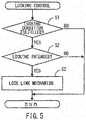
- FIG. 5 is a flowchart for illustrating the locking control by the locking mechanism controller 86.
- the locking mechanism controller 86 determines in step S1 whether the locking condition is established. More specifically, the locking condition determiner 86A determines whether all of the above-described conditions 1 to 3 are satisfied.
- the locking condition determiner 86A determines whether the link mechanism 36 is in an unlocked state by referring to an input position signal D3. If the unlocked position signal D3 is input, the condition 1 is satisfied.
- the locking condition determiner 86A determines whether the present throttle opening degree is zero by referring to an input throttle opening degree signal D1. If the throttle opening degree is zero, in other words, if the throttle valve is closed, the condition 2 is satisfied.
- the locking condition determiner 86A determines whether the present vehicle speed is lower than a prescribed vehicle speed (10 km/h for example) by referring to an input vehicle speed signal D2. If the present vehicle speed is lower than the prescribed vehicle speed, the condition 3 is satisfied.
- the locking mechanism controller 86 ends the locking control. On the other hand, if all of the conditions 1 to 3 are satisfied, the locking mechanism controller 86 determines in step S2 whether the rider intends to lock the link mechanism 36. More specifically, the signal input determiner 86B determines whether an input condition is fulfilled. The input condition is fulfilled if the following condition 4 is satisfied.
- the signal input determiner 86B determines whether the operation signal D4 is input. If the operation signal D4 is input, the condition 4 is satisfied.
- the operation signal D4 may be input before or after fulfillment of the locking condition.
- the locking mechanism controller 86 ends the locking control. On the other hand, if the condition 4 is satisfied, the locking mechanism controller 86 locks the link mechanism 36 in step S3. More specifically, the locking controller 86C drives the actuator 78 to lock the link mechanism 36. The locking mechanism controller 86 subsequently ends the locking control.
- the notifying controller 86D controls the locking notifying unit 112 to notify a locked state of the link mechanism 36 if the link mechanism 36 is locked and relative displacement between the pair of front wheels 14L and 14R in the vertical direction exceeds a prescribed upper limit.
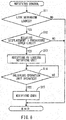
- FIG. 6 is a flowchart for illustrating the notifying control by the notifying controller 86D.
- the notifying controller 86D determines whether the link mechanism 36 is in a locked state. More specifically, the notifying controller 86D refers to an input position signal D3 and determines whether the link mechanism 36 is locked. If a locked position signal D3 is input, the link mechanism 36 is locked.
- step S11 If the link mechanism 36 is not locked (NO in step S11), the notifying controller 86D ends the notifying control. On the other hand, if the link mechanism 36 is locked (YES in step S11), the notifying controller 86D (the state determiner 104 to be specific) determines in step S12 whether relative displacement between the front wheels 14L and 14R in the vertical direction exceeds the prescribed upper limit.
- the notifying controller 86D ends the notifying control. On the other hand, if the relative displacement between the front wheels 14L and 14R in the vertical direction exceeds the prescribed upper limit (YES in step S12), the notifying controller 86D carries out notification by the locking notifying unit 112 in step S13. More specifically, the notifying controller controls the operation of the locking notifying unit 112 to start to notify the rider of the locked state of the link mechanism 36.
- the notifying controller 86D determines in step S14 whether the unlocking operation unit 106 has been operated. If a signal from the unlocking operation unit 106 is input, the unlocking operation unit 106 has been operated.
- step S14 If the unlocking operation unit 106 has not been operated (NO in step S14), the notifying controller 86D stands by until the unlocking operation unit 106 is operated. At the time, the locking notifying unit 112 continues to notify the locked state of the link mechanism 36. On the other hand, if the unlocking operation unit 106 has been operated (YES in step S14), the notifying controller 86D ends the notification by the locking notifying unit 112 in step S15. The notifying controller 86D subsequently ends the notifying control.
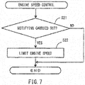
- FIG. 7 is a flowchart for illustrating the engine speed control by the engine controller 88.
- the engine controller 88 determines in step S21 whether the link mechanism 36 is locked and relative displacement between the pair of front wheels 14L and 14R in the vertical direction exceeds a prescribed upper limit, in other words whether notification by the locking notifying unit 112 has been carried out according to the embodiment.
- the determination can be carried out for example by referring to a signal from the notifying controller 86D (a signal indicates that notification by the locking notifying unit 112 has been carried out).
- step S21 If notification by the locking notifying unit 112 has not been carried out (NO in step S21), the engine controller 88 ends the engine speed control. On the other hand, if the notification by the locking notifying unit 112 has been carried out (YES in step S21), the engine controller 88 limits the engine speed in step S22. More specifically, the limiter 88A operates so that the engine speed of the engine 94 does not exceed a prescribed upper limit if the rider operates to open the throttle. The engine speed of the engine 94 can be obtained by referring to an output from the engine speed detector 92 provided in the saddle riding type vehicle 10 (see Fig. 4 ). Subsequently, the engine controller 88 ends the engine speed control.
- the limiting by the engine controller 88 ends if for example the notification by the locking notifying unit 112 ends.
- the link mechanism 36 can be locked.
- the vehicle is often in its upright state.
- the "upright state” refers to the state in which the side surfaces of the front wheels 14L and 14R are parallel to the direction of gravity (the vertical direction), in other words, the state in which the axle for the front wheels 14L and 14R is orthogonal to the direction of gravity.
- the rider may sometimes feel as if the front wheels 14L and 14R are locked as they are in the same position in the direction of gravity.
- the front wheels 14L and 14R may be locked as they are relatively displaced in the direction of gravity because of a sloped road surface or steps. In this case, if the vehicle is moved to a location on a flat road surface, the vehicle may be tilted.
- the locked state of the link mechanism 36 is notified while the front wheels 14L and 14R are shifted in the vertical direction. Therefore, an actual state of the vehicle and a state of the vehicle understood by the rider are hardly different.
- the locked state of the link mechanism 36 continues to be notified. Therefore, it can be easier to let the rider aware of the locked state of the link mechanism 36.
- the locked state of the link mechanism 36 is notified until the link mechanism 36 is unlocked. Therefore, it can be easier to let the rider aware of the state in which the link mechanism 36 is locked while the front wheels 14L and 14R are relatively displaced in the direction of gravity.
- the engine controller 88 includes the limiter 88A but the engine controller 88 does not have to include the limiter 88A.
- the first displacement detector 47L detects a swing angle of the lower left arm 44L
- the second displacement detector 47R detects a swing angle of the upper right arm 42R while the first displacement detector may detect a swing angle of the lower left arm 44L and the second displacement detector may detect a swing angle of the lower right arm 44R or the first displacement detector may detect a swing angle of the upper left arm 42L and the second displacement detector may detect a swing angle of the upper right arm 42R.
- the locked state of the link mechanism 36 continues to be notified while the notification does not have to continue.
- the engine speed of the engine 94 it is determined whether notification by the locking notifying unit 112 is carried out and if the notification by the locking notifying unit 112 is carried out, the engine speed of the engine 94 does not exceed a prescribed upper limit, while if the notification by the locking notifying unit 112 does not continue to be carried out, it may be determined whether the link mechanism 36 is locked and whether relative displacement between the front wheels 14L and 14R in the vertical direction exceeds a prescribed upper limit and if the link mechanism 36 is locked and the relative displacement between the front wheels 14L and 14R in the vertical direction exceeds the prescribed upper limit, the engine speed of the engine 94 is kept less than the prescribed upper limit.
Applications Claiming Priority (2)
| Application Number | Priority Date | Filing Date | Title |
|---|---|---|---|
| JP2014060197 | 2014-03-24 | ||
| PCT/JP2015/057731 WO2015146679A1 (fr) | 2014-03-24 | 2015-03-16 | Véhicule de type à selle |
Publications (3)
| Publication Number | Publication Date |
|---|---|
| EP3124364A1 true EP3124364A1 (fr) | 2017-02-01 |
| EP3124364A4 EP3124364A4 (fr) | 2017-07-19 |
| EP3124364B1 EP3124364B1 (fr) | 2019-05-08 |
Family
ID=54195202
Family Applications (1)
| Application Number | Title | Priority Date | Filing Date |
|---|---|---|---|
| EP15768153.7A Active EP3124364B1 (fr) | 2014-03-24 | 2015-03-16 | Véhicule de type à selle |
Country Status (6)
| Country | Link |
|---|---|
| US (1) | US10086900B2 (fr) |
| EP (1) | EP3124364B1 (fr) |
| JP (1) | JPWO2015146679A1 (fr) |
| CA (1) | CA2943761C (fr) |
| ES (1) | ES2727606T3 (fr) |
| WO (1) | WO2015146679A1 (fr) |
Families Citing this family (16)
| Publication number | Priority date | Publication date | Assignee | Title |
|---|---|---|---|---|
| WO2015146680A1 (fr) * | 2014-03-24 | 2015-10-01 | ヤマハ発動機株式会社 | Véhicule à selle |
| WO2017082424A1 (fr) * | 2015-11-13 | 2017-05-18 | ヤマハ発動機株式会社 | Véhicule inclinable |
| JP6648155B2 (ja) * | 2015-11-13 | 2020-02-14 | ヤマハ発動機株式会社 | 傾斜車両 |
| ITUB20159521A1 (it) * | 2015-12-28 | 2017-06-28 | Piaggio & C Spa | Motoveicolo rollante con controllo di rollio |
| ITUB20159670A1 (it) * | 2015-12-28 | 2017-06-28 | Piaggio & C Spa | Avantreno di motoveicolo rollante con blocco di rollio |
| IT201600123275A1 (it) * | 2016-12-05 | 2018-06-05 | Piaggio & C Spa | Motociclo con due ruote anteriori sterzanti e uno sterzo a rapporto di sterzata variabile |
| IT201600129497A1 (it) | 2016-12-21 | 2018-06-21 | Piaggio & C Spa | Avantreno di motoveicolo rollante con blocco di rollio |
| IT201600129502A1 (it) | 2016-12-21 | 2018-06-21 | Piaggio & C Spa | Avantreno di motoveicolo rollante con controllo di rollio |
| IT201600129510A1 (it) | 2016-12-21 | 2018-06-21 | Piaggio & C Spa | Avantreno di motoveicolo rollante con controllo di rollio |
| IT201600129491A1 (it) | 2016-12-21 | 2018-06-21 | Piaggio & C Spa | Avantreno di motoveicolo rollante con blocco di rollio |
| IT201600129489A1 (it) | 2016-12-21 | 2018-06-21 | Piaggio & C Spa | Avantreno di motoveicolo rollante con blocco di rollio |
| JP2018144698A (ja) * | 2017-03-07 | 2018-09-20 | ヤマハ発動機株式会社 | 車両 |
| JP2018144697A (ja) * | 2017-03-07 | 2018-09-20 | ヤマハ発動機株式会社 | 車両 |
| US10131398B1 (en) * | 2017-05-17 | 2018-11-20 | Kuianda Company Limited | Shock-absorbent structure of electric carrier |
| WO2018211973A1 (fr) | 2017-05-19 | 2018-11-22 | ヤマハ発動機株式会社 | Véhicule à inclinaison |
| CN109693745B (zh) * | 2018-12-29 | 2021-04-02 | 北京牛电信息技术有限责任公司 | 一种车辆的倾斜装置、方法及车辆 |
Family Cites Families (48)
| Publication number | Priority date | Publication date | Assignee | Title |
|---|---|---|---|---|
| JPS60163752A (ja) * | 1984-02-06 | 1985-08-26 | Yamaha Motor Co Ltd | 荒地走行用車輛のブレ−キ装置 |
| JPS60193880U (ja) * | 1984-06-04 | 1985-12-24 | 本田技研工業株式会社 | 車両のキヤリア装置 |
| JPS6218378A (ja) * | 1985-07-17 | 1987-01-27 | 本田技研工業株式会社 | 鞍乗型車両におけるリヤフエンダ装置 |
| US4787470A (en) * | 1986-06-30 | 1988-11-29 | Yamaha Hatsudoki Kabushiki Kaisha | Three wheel vehicle |
| JP2918116B2 (ja) * | 1989-06-22 | 1999-07-12 | ヤマハ発動機株式会社 | スクータ型自動二,三輪車の燃料供給部構造 |
| ITPN20000034A1 (it) * | 2000-06-02 | 2001-12-02 | Aprilia Spa | Perfezionamenti ai veicoli aventi due ruote anteriori rollanti e sterzanti e almeno una ruota motrice posteriore |
| US6588529B2 (en) * | 2000-07-05 | 2003-07-08 | Yamaha Hatsudoki Kabishuki Kaisha | Body cover and structure for motorcycle |
| JP4287136B2 (ja) * | 2002-12-20 | 2009-07-01 | 本田技研工業株式会社 | 車両のサスペンション配置構造 |
| ITMI20031108A1 (it) * | 2003-06-03 | 2004-12-04 | Piaggio & C Spa | Veicolo rollante a tre ruote con due ruote anteriori sterzanti |
| CN100448736C (zh) * | 2003-10-21 | 2009-01-07 | 罗德尼·伊恩·罗林森 | 侧向可倾式四轮车 |
| US9487234B1 (en) * | 2003-12-09 | 2016-11-08 | Mystery Designs, LLC | Control system for tilting motorcycle trike |
| ITMI20040172A1 (it) * | 2004-02-04 | 2004-05-04 | Piaggio & C Spa | Dispositivo di arresto corsa delle sospensioni di un veicolo |
| ITMI20040171A1 (it) | 2004-02-04 | 2004-05-04 | Piaggio & C Spa | Dispositivo anti-rollio per veicoli |
| JP2006088894A (ja) * | 2004-09-24 | 2006-04-06 | Yamaha Motor Co Ltd | 鞍乗型車両 |
| JP2006341837A (ja) | 2005-06-10 | 2006-12-21 | Piaggio & C Spa | 車両動作ユニットのための電子制御システム |
| US7648148B1 (en) * | 2005-07-06 | 2010-01-19 | Bombardier Recreational Products Inc. | Leaning vehicle with tilting front wheels and suspension therefor |
| JP2009509857A (ja) * | 2005-09-30 | 2009-03-12 | ハーレー−ダビッドソン・モーター・カンパニー・グループ・インコーポレーテッド | 傾斜サスペンションマシン |
| JP4886319B2 (ja) * | 2006-02-27 | 2012-02-29 | 本田技研工業株式会社 | 車両の減速装置 |
| USD547242S1 (en) * | 2006-03-02 | 2007-07-24 | Piaggio & C. S.P.A. | Motorcycle |
| EP2019772B1 (fr) * | 2006-04-26 | 2013-08-28 | Vectrix International Limited | Véhicule avec système d'inclinaison verrouillable |
| US20090107754A1 (en) * | 2007-10-31 | 2009-04-30 | Harley-Davidson Motor Company Group, Inc. | Vehicle having a detachable pulley mount |
| USD598328S1 (en) * | 2008-05-12 | 2009-08-18 | Piaggio & C. S.P.A. | Motorcycle |
| JP5204555B2 (ja) * | 2008-05-29 | 2013-06-05 | ヤマハ発動機株式会社 | 鞍乗型車両 |
| US8251375B2 (en) * | 2008-07-31 | 2012-08-28 | Yamaha Hatsudoki Kabushiki Kaisha | Body leaning control system, and a saddle riding type vehicle having the same |
| JP5204637B2 (ja) * | 2008-12-16 | 2013-06-05 | ヤマハ発動機株式会社 | 鞍乗型車両 |
| JP2011045184A (ja) * | 2009-08-20 | 2011-03-03 | Suzuki Motor Corp | 電動車駆動制御装置及び方法 |
| TW201117997A (en) * | 2009-11-27 | 2011-06-01 | Kwang Yang Motor Co | Anti-turnover device for vehicle having two front wheels |
| US8746717B2 (en) | 2009-12-17 | 2014-06-10 | Yamaha Hatsudoki Kabushiki Kaisha | Saddle riding type vehicle |
| IT1401130B1 (it) * | 2010-07-16 | 2013-07-12 | Piaggio & C Spa | Sistema di sospensione per motoveicoli |
| JP5617509B2 (ja) | 2010-10-07 | 2014-11-05 | トヨタ自動車株式会社 | 車体傾斜装置 |
| JP5474749B2 (ja) | 2010-12-15 | 2014-04-16 | 本田技研工業株式会社 | 鞍乗型車両のサスペンション構造 |
| JP5694788B2 (ja) * | 2011-01-17 | 2015-04-01 | 本田技研工業株式会社 | 鞍乗型車両 |
| JP2013022993A (ja) | 2011-07-19 | 2013-02-04 | Toyota Motor Corp | サスペンションシステム |
| ITMI20111469A1 (it) * | 2011-08-01 | 2013-02-02 | Piaggio & C Spa | Sistema di regolazione dei proiettori anteriori di un veicolo basculante con meccanismo di rollio |
| CN202414056U (zh) * | 2012-01-14 | 2012-09-05 | 于金君 | 一种能够倾斜车体的倒三轮摩托车 |
| JP5969232B2 (ja) * | 2012-03-22 | 2016-08-17 | 本田技研工業株式会社 | 鞍乗り型車両のラジエータホース配置構造 |
| JP5889685B2 (ja) * | 2012-03-22 | 2016-03-22 | 本田技研工業株式会社 | 鞍乗り型車両のキャニスター配置構造 |
| JP5868780B2 (ja) * | 2012-05-23 | 2016-02-24 | アイシン精機株式会社 | 車両制御装置、車両制御方法、及びプログラム |
| JP5775560B2 (ja) * | 2013-12-06 | 2015-09-09 | 本田技研工業株式会社 | 鞍乗り型車両 |
| JP2015113074A (ja) * | 2013-12-13 | 2015-06-22 | ヤマハ発動機株式会社 | 鞍乗型車両 |
| ES2630206T3 (es) * | 2014-01-31 | 2017-08-18 | Yamaha Hatsudoki Kabushiki Kaisha | Vehículo |
| WO2015115110A1 (fr) * | 2014-01-31 | 2015-08-06 | ヤマハ発動機株式会社 | Véhicule |
| JP6074543B2 (ja) * | 2014-03-24 | 2017-02-01 | ヤマハ発動機株式会社 | 鞍乗型車両 |
| WO2015146660A1 (fr) * | 2014-03-24 | 2015-10-01 | ヤマハ発動機株式会社 | Véhicule à selle |
| WO2015146680A1 (fr) * | 2014-03-24 | 2015-10-01 | ヤマハ発動機株式会社 | Véhicule à selle |
| JP6369217B2 (ja) * | 2014-08-20 | 2018-08-08 | スズキ株式会社 | 燃料電池二輪車 |
| JP6086889B2 (ja) * | 2014-09-30 | 2017-03-01 | 本田技研工業株式会社 | 後部燃料タンク |
| JP6413873B2 (ja) * | 2015-03-24 | 2018-10-31 | スズキ株式会社 | 鞍乗型燃料電池車両 |
-
2015
- 2015-03-16 EP EP15768153.7A patent/EP3124364B1/fr active Active
- 2015-03-16 US US15/128,456 patent/US10086900B2/en active Active
- 2015-03-16 CA CA2943761A patent/CA2943761C/fr active Active
- 2015-03-16 ES ES15768153T patent/ES2727606T3/es active Active
- 2015-03-16 JP JP2016510257A patent/JPWO2015146679A1/ja active Pending
- 2015-03-16 WO PCT/JP2015/057731 patent/WO2015146679A1/fr active Application Filing
Also Published As
| Publication number | Publication date |
|---|---|
| EP3124364B1 (fr) | 2019-05-08 |
| JPWO2015146679A1 (ja) | 2017-04-13 |
| US10086900B2 (en) | 2018-10-02 |
| CA2943761A1 (fr) | 2015-10-01 |
| WO2015146679A1 (fr) | 2015-10-01 |
| EP3124364A4 (fr) | 2017-07-19 |
| US20170106935A1 (en) | 2017-04-20 |
| ES2727606T3 (es) | 2019-10-17 |
| CA2943761C (fr) | 2018-08-14 |
Similar Documents
| Publication | Publication Date | Title |
|---|---|---|
| CA2943761C (fr) | Vehicule du type a selle dote de deux roues avant et d'un lien verrouillable | |
| CA2943760C (fr) | Vehicule de type a selle equipe de deux roues avant et d'un lien verrouillable | |
| EP3124365B1 (fr) | Véhicule de type à selle | |
| US10668972B2 (en) | Saddle riding type vehicle | |
| EP2942247B1 (fr) | Système de frein et véhicule | |
| US7044489B2 (en) | Steering damper system | |
| US10384739B2 (en) | Control system of the trim of vehicles with more than two wheels | |
| EP2933156B1 (fr) | Système de freinage et véhicule | |
| JP5798682B2 (ja) | ステアリングダンパおよびそれを備えた鞍乗型車両 | |
| US20190078640A1 (en) | Damper control device and suspension device | |
| JP2012171567A (ja) | 車両用ステアリング緩衝装置 |
Legal Events
| Date | Code | Title | Description |
|---|---|---|---|
| STAA | Information on the status of an ep patent application or granted ep patent |
Free format text: STATUS: THE INTERNATIONAL PUBLICATION HAS BEEN MADE |
|
| PUAI | Public reference made under article 153(3) epc to a published international application that has entered the european phase |
Free format text: ORIGINAL CODE: 0009012 |
|
| STAA | Information on the status of an ep patent application or granted ep patent |
Free format text: STATUS: REQUEST FOR EXAMINATION WAS MADE |
|
| 17P | Request for examination filed |
Effective date: 20160923 |
|
| AK | Designated contracting states |
Kind code of ref document: A1 Designated state(s): AL AT BE BG CH CY CZ DE DK EE ES FI FR GB GR HR HU IE IS IT LI LT LU LV MC MK MT NL NO PL PT RO RS SE SI SK SM TR |
|
| AX | Request for extension of the european patent |
Extension state: BA ME |
|
| DAV | Request for validation of the european patent (deleted) | ||
| DAX | Request for extension of the european patent (deleted) | ||
| STAA | Information on the status of an ep patent application or granted ep patent |
Free format text: STATUS: EXAMINATION IS IN PROGRESS |
|
| A4 | Supplementary search report drawn up and despatched |
Effective date: 20170619 |
|
| RIC1 | Information provided on ipc code assigned before grant |
Ipc: B62K 5/05 20130101ALI20170612BHEP Ipc: B62K 5/08 20060101AFI20170612BHEP Ipc: B62K 5/027 20130101ALI20170612BHEP Ipc: B62K 5/10 20130101ALI20170612BHEP Ipc: B62K 25/04 20060101ALI20170612BHEP Ipc: B62K 5/00 20130101ALI20170612BHEP |
|
| 17Q | First examination report despatched |
Effective date: 20170707 |
|
| GRAP | Despatch of communication of intention to grant a patent |
Free format text: ORIGINAL CODE: EPIDOSNIGR1 |
|
| STAA | Information on the status of an ep patent application or granted ep patent |
Free format text: STATUS: GRANT OF PATENT IS INTENDED |
|
| INTG | Intention to grant announced |
Effective date: 20181023 |
|
| GRAS | Grant fee paid |
Free format text: ORIGINAL CODE: EPIDOSNIGR3 |
|
| GRAA | (expected) grant |
Free format text: ORIGINAL CODE: 0009210 |
|
| STAA | Information on the status of an ep patent application or granted ep patent |
Free format text: STATUS: THE PATENT HAS BEEN GRANTED |
|
| AK | Designated contracting states |
Kind code of ref document: B1 Designated state(s): AL AT BE BG CH CY CZ DE DK EE ES FI FR GB GR HR HU IE IS IT LI LT LU LV MC MK MT NL NO PL PT RO RS SE SI SK SM TR |
|
| REG | Reference to a national code |
Ref country code: GB Ref legal event code: FG4D |
|
| REG | Reference to a national code |
Ref country code: CH Ref legal event code: EP Ref country code: AT Ref legal event code: REF Ref document number: 1129708 Country of ref document: AT Kind code of ref document: T Effective date: 20190515 |
|
| REG | Reference to a national code |
Ref country code: DE Ref legal event code: R096 Ref document number: 602015029934 Country of ref document: DE Ref country code: IE Ref legal event code: FG4D |
|
| REG | Reference to a national code |
Ref country code: NL Ref legal event code: MP Effective date: 20190508 |
|
| REG | Reference to a national code |
Ref country code: LT Ref legal event code: MG4D |
|
| REG | Reference to a national code |
Ref country code: ES Ref legal event code: FG2A Ref document number: 2727606 Country of ref document: ES Kind code of ref document: T3 Effective date: 20191017 |
|
| PG25 | Lapsed in a contracting state [announced via postgrant information from national office to epo] |
Ref country code: HR Free format text: LAPSE BECAUSE OF FAILURE TO SUBMIT A TRANSLATION OF THE DESCRIPTION OR TO PAY THE FEE WITHIN THE PRESCRIBED TIME-LIMIT Effective date: 20190508 Ref country code: NL Free format text: LAPSE BECAUSE OF FAILURE TO SUBMIT A TRANSLATION OF THE DESCRIPTION OR TO PAY THE FEE WITHIN THE PRESCRIBED TIME-LIMIT Effective date: 20190508 Ref country code: SE Free format text: LAPSE BECAUSE OF FAILURE TO SUBMIT A TRANSLATION OF THE DESCRIPTION OR TO PAY THE FEE WITHIN THE PRESCRIBED TIME-LIMIT Effective date: 20190508 Ref country code: LT Free format text: LAPSE BECAUSE OF FAILURE TO SUBMIT A TRANSLATION OF THE DESCRIPTION OR TO PAY THE FEE WITHIN THE PRESCRIBED TIME-LIMIT Effective date: 20190508 Ref country code: NO Free format text: LAPSE BECAUSE OF FAILURE TO SUBMIT A TRANSLATION OF THE DESCRIPTION OR TO PAY THE FEE WITHIN THE PRESCRIBED TIME-LIMIT Effective date: 20190808 Ref country code: FI Free format text: LAPSE BECAUSE OF FAILURE TO SUBMIT A TRANSLATION OF THE DESCRIPTION OR TO PAY THE FEE WITHIN THE PRESCRIBED TIME-LIMIT Effective date: 20190508 Ref country code: PT Free format text: LAPSE BECAUSE OF FAILURE TO SUBMIT A TRANSLATION OF THE DESCRIPTION OR TO PAY THE FEE WITHIN THE PRESCRIBED TIME-LIMIT Effective date: 20190908 Ref country code: AL Free format text: LAPSE BECAUSE OF FAILURE TO SUBMIT A TRANSLATION OF THE DESCRIPTION OR TO PAY THE FEE WITHIN THE PRESCRIBED TIME-LIMIT Effective date: 20190508 |
|
| PG25 | Lapsed in a contracting state [announced via postgrant information from national office to epo] |
Ref country code: BG Free format text: LAPSE BECAUSE OF FAILURE TO SUBMIT A TRANSLATION OF THE DESCRIPTION OR TO PAY THE FEE WITHIN THE PRESCRIBED TIME-LIMIT Effective date: 20190808 Ref country code: GR Free format text: LAPSE BECAUSE OF FAILURE TO SUBMIT A TRANSLATION OF THE DESCRIPTION OR TO PAY THE FEE WITHIN THE PRESCRIBED TIME-LIMIT Effective date: 20190809 Ref country code: LV Free format text: LAPSE BECAUSE OF FAILURE TO SUBMIT A TRANSLATION OF THE DESCRIPTION OR TO PAY THE FEE WITHIN THE PRESCRIBED TIME-LIMIT Effective date: 20190508 Ref country code: RS Free format text: LAPSE BECAUSE OF FAILURE TO SUBMIT A TRANSLATION OF THE DESCRIPTION OR TO PAY THE FEE WITHIN THE PRESCRIBED TIME-LIMIT Effective date: 20190508 |
|
| REG | Reference to a national code |
Ref country code: AT Ref legal event code: MK05 Ref document number: 1129708 Country of ref document: AT Kind code of ref document: T Effective date: 20190508 |
|
| PG25 | Lapsed in a contracting state [announced via postgrant information from national office to epo] |
Ref country code: EE Free format text: LAPSE BECAUSE OF FAILURE TO SUBMIT A TRANSLATION OF THE DESCRIPTION OR TO PAY THE FEE WITHIN THE PRESCRIBED TIME-LIMIT Effective date: 20190508 Ref country code: DK Free format text: LAPSE BECAUSE OF FAILURE TO SUBMIT A TRANSLATION OF THE DESCRIPTION OR TO PAY THE FEE WITHIN THE PRESCRIBED TIME-LIMIT Effective date: 20190508 Ref country code: SK Free format text: LAPSE BECAUSE OF FAILURE TO SUBMIT A TRANSLATION OF THE DESCRIPTION OR TO PAY THE FEE WITHIN THE PRESCRIBED TIME-LIMIT Effective date: 20190508 Ref country code: CZ Free format text: LAPSE BECAUSE OF FAILURE TO SUBMIT A TRANSLATION OF THE DESCRIPTION OR TO PAY THE FEE WITHIN THE PRESCRIBED TIME-LIMIT Effective date: 20190508 Ref country code: RO Free format text: LAPSE BECAUSE OF FAILURE TO SUBMIT A TRANSLATION OF THE DESCRIPTION OR TO PAY THE FEE WITHIN THE PRESCRIBED TIME-LIMIT Effective date: 20190508 Ref country code: AT Free format text: LAPSE BECAUSE OF FAILURE TO SUBMIT A TRANSLATION OF THE DESCRIPTION OR TO PAY THE FEE WITHIN THE PRESCRIBED TIME-LIMIT Effective date: 20190508 |
|
| REG | Reference to a national code |
Ref country code: DE Ref legal event code: R097 Ref document number: 602015029934 Country of ref document: DE |
|
| PG25 | Lapsed in a contracting state [announced via postgrant information from national office to epo] |
Ref country code: SM Free format text: LAPSE BECAUSE OF FAILURE TO SUBMIT A TRANSLATION OF THE DESCRIPTION OR TO PAY THE FEE WITHIN THE PRESCRIBED TIME-LIMIT Effective date: 20190508 Ref country code: IT Free format text: LAPSE BECAUSE OF FAILURE TO SUBMIT A TRANSLATION OF THE DESCRIPTION OR TO PAY THE FEE WITHIN THE PRESCRIBED TIME-LIMIT Effective date: 20190508 |
|
| PLBE | No opposition filed within time limit |
Free format text: ORIGINAL CODE: 0009261 |
|
| STAA | Information on the status of an ep patent application or granted ep patent |
Free format text: STATUS: NO OPPOSITION FILED WITHIN TIME LIMIT |
|
| PG25 | Lapsed in a contracting state [announced via postgrant information from national office to epo] |
Ref country code: TR Free format text: LAPSE BECAUSE OF FAILURE TO SUBMIT A TRANSLATION OF THE DESCRIPTION OR TO PAY THE FEE WITHIN THE PRESCRIBED TIME-LIMIT Effective date: 20190508 |
|
| 26N | No opposition filed |
Effective date: 20200211 |
|
| PG25 | Lapsed in a contracting state [announced via postgrant information from national office to epo] |
Ref country code: PL Free format text: LAPSE BECAUSE OF FAILURE TO SUBMIT A TRANSLATION OF THE DESCRIPTION OR TO PAY THE FEE WITHIN THE PRESCRIBED TIME-LIMIT Effective date: 20190508 |
|
| PG25 | Lapsed in a contracting state [announced via postgrant information from national office to epo] |
Ref country code: SI Free format text: LAPSE BECAUSE OF FAILURE TO SUBMIT A TRANSLATION OF THE DESCRIPTION OR TO PAY THE FEE WITHIN THE PRESCRIBED TIME-LIMIT Effective date: 20190508 |
|
| PG25 | Lapsed in a contracting state [announced via postgrant information from national office to epo] |
Ref country code: MC Free format text: LAPSE BECAUSE OF FAILURE TO SUBMIT A TRANSLATION OF THE DESCRIPTION OR TO PAY THE FEE WITHIN THE PRESCRIBED TIME-LIMIT Effective date: 20190508 |
|
| REG | Reference to a national code |
Ref country code: BE Ref legal event code: MM Effective date: 20200331 |
|
| PG25 | Lapsed in a contracting state [announced via postgrant information from national office to epo] |
Ref country code: LU Free format text: LAPSE BECAUSE OF NON-PAYMENT OF DUE FEES Effective date: 20200316 |
|
| PG25 | Lapsed in a contracting state [announced via postgrant information from national office to epo] |
Ref country code: IE Free format text: LAPSE BECAUSE OF NON-PAYMENT OF DUE FEES Effective date: 20200316 |
|
| PG25 | Lapsed in a contracting state [announced via postgrant information from national office to epo] |
Ref country code: BE Free format text: LAPSE BECAUSE OF NON-PAYMENT OF DUE FEES Effective date: 20200331 |
|
| PG25 | Lapsed in a contracting state [announced via postgrant information from national office to epo] |
Ref country code: MT Free format text: LAPSE BECAUSE OF FAILURE TO SUBMIT A TRANSLATION OF THE DESCRIPTION OR TO PAY THE FEE WITHIN THE PRESCRIBED TIME-LIMIT Effective date: 20190508 Ref country code: CY Free format text: LAPSE BECAUSE OF FAILURE TO SUBMIT A TRANSLATION OF THE DESCRIPTION OR TO PAY THE FEE WITHIN THE PRESCRIBED TIME-LIMIT Effective date: 20190508 |
|
| PG25 | Lapsed in a contracting state [announced via postgrant information from national office to epo] |
Ref country code: MK Free format text: LAPSE BECAUSE OF FAILURE TO SUBMIT A TRANSLATION OF THE DESCRIPTION OR TO PAY THE FEE WITHIN THE PRESCRIBED TIME-LIMIT Effective date: 20190508 Ref country code: IS Free format text: LAPSE BECAUSE OF FAILURE TO SUBMIT A TRANSLATION OF THE DESCRIPTION OR TO PAY THE FEE WITHIN THE PRESCRIBED TIME-LIMIT Effective date: 20190908 |
|
| PGFP | Annual fee paid to national office [announced via postgrant information from national office to epo] |
Ref country code: FR Payment date: 20230324 Year of fee payment: 9 |
|
| PGFP | Annual fee paid to national office [announced via postgrant information from national office to epo] |
Ref country code: GB Payment date: 20230322 Year of fee payment: 9 Ref country code: DE Payment date: 20230321 Year of fee payment: 9 |
|
| P01 | Opt-out of the competence of the unified patent court (upc) registered |
Effective date: 20230527 |
|
| PGFP | Annual fee paid to national office [announced via postgrant information from national office to epo] |
Ref country code: ES Payment date: 20230529 Year of fee payment: 9 Ref country code: CH Payment date: 20230401 Year of fee payment: 9 |