EP3124115B1 - Wabenstruktur zur verwendung als abgasreinigungskatalysator sowie verfahren zu seiner herstellung - Google Patents
Wabenstruktur zur verwendung als abgasreinigungskatalysator sowie verfahren zu seiner herstellung Download PDFInfo
- Publication number
- EP3124115B1 EP3124115B1 EP15768958.9A EP15768958A EP3124115B1 EP 3124115 B1 EP3124115 B1 EP 3124115B1 EP 15768958 A EP15768958 A EP 15768958A EP 3124115 B1 EP3124115 B1 EP 3124115B1
- Authority
- EP
- European Patent Office
- Prior art keywords
- zeolite
- honeycomb structure
- exhaust gas
- fiber sheet
- denitration
- Prior art date
- Legal status (The legal status is an assumption and is not a legal conclusion. Google has not performed a legal analysis and makes no representation as to the accuracy of the status listed.)
- Active
Links
- 239000003054 catalyst Substances 0.000 title claims description 78
- 238000004519 manufacturing process Methods 0.000 title claims description 11
- 238000004140 cleaning Methods 0.000 title description 37
- 238000000034 method Methods 0.000 title description 23
- HNPSIPDUKPIQMN-UHFFFAOYSA-N dioxosilane;oxo(oxoalumanyloxy)alumane Chemical compound O=[Si]=O.O=[Al]O[Al]=O HNPSIPDUKPIQMN-UHFFFAOYSA-N 0.000 claims description 78
- 229910021536 Zeolite Inorganic materials 0.000 claims description 73
- 239000010457 zeolite Substances 0.000 claims description 73
- 239000002245 particle Substances 0.000 claims description 47
- 239000011230 binding agent Substances 0.000 claims description 32
- 229910052797 bismuth Inorganic materials 0.000 claims description 30
- JCXGWMGPZLAOME-UHFFFAOYSA-N bismuth atom Chemical compound [Bi] JCXGWMGPZLAOME-UHFFFAOYSA-N 0.000 claims description 29
- MCMNRKCIXSYSNV-UHFFFAOYSA-N Zirconium dioxide Chemical compound O=[Zr]=O MCMNRKCIXSYSNV-UHFFFAOYSA-N 0.000 claims description 26
- 239000012784 inorganic fiber Substances 0.000 claims description 24
- 239000003365 glass fiber Substances 0.000 claims description 19
- 239000002904 solvent Substances 0.000 claims description 11
- 150000001875 compounds Chemical class 0.000 claims description 10
- 238000009826 distribution Methods 0.000 claims description 5
- 125000002887 hydroxy group Chemical group [H]O* 0.000 claims description 5
- 230000001186 cumulative effect Effects 0.000 claims description 4
- 238000007561 laser diffraction method Methods 0.000 claims description 4
- MWUXSHHQAYIFBG-UHFFFAOYSA-N Nitric oxide Chemical compound O=[N] MWUXSHHQAYIFBG-UHFFFAOYSA-N 0.000 description 75
- 239000007789 gas Substances 0.000 description 68
- 239000011521 glass Substances 0.000 description 44
- 239000002002 slurry Substances 0.000 description 42
- XTQHKBHJIVJGKJ-UHFFFAOYSA-N sulfur monoxide Chemical compound S=O XTQHKBHJIVJGKJ-UHFFFAOYSA-N 0.000 description 40
- TXKMVPPZCYKFAC-UHFFFAOYSA-N disulfur monoxide Inorganic materials O=S=S TXKMVPPZCYKFAC-UHFFFAOYSA-N 0.000 description 34
- VYPSYNLAJGMNEJ-UHFFFAOYSA-N Silicium dioxide Chemical compound O=[Si]=O VYPSYNLAJGMNEJ-UHFFFAOYSA-N 0.000 description 32
- 238000002485 combustion reaction Methods 0.000 description 23
- 238000011156 evaluation Methods 0.000 description 23
- 238000012360 testing method Methods 0.000 description 21
- 239000000758 substrate Substances 0.000 description 19
- AKEJUJNQAAGONA-UHFFFAOYSA-N sulfur trioxide Chemical compound O=S(=O)=O AKEJUJNQAAGONA-UHFFFAOYSA-N 0.000 description 18
- 239000000377 silicon dioxide Substances 0.000 description 16
- LYCAIKOWRPUZTN-UHFFFAOYSA-N Ethylene glycol Chemical compound OCCO LYCAIKOWRPUZTN-UHFFFAOYSA-N 0.000 description 15
- OKKJLVBELUTLKV-UHFFFAOYSA-N Methanol Chemical compound OC OKKJLVBELUTLKV-UHFFFAOYSA-N 0.000 description 15
- 238000005342 ion exchange Methods 0.000 description 10
- 229910052751 metal Inorganic materials 0.000 description 10
- 239000000203 mixture Substances 0.000 description 10
- XLYOFNOQVPJJNP-UHFFFAOYSA-N water Substances O XLYOFNOQVPJJNP-UHFFFAOYSA-N 0.000 description 10
- 239000007864 aqueous solution Substances 0.000 description 9
- 239000003638 chemical reducing agent Substances 0.000 description 9
- 230000000052 comparative effect Effects 0.000 description 9
- 239000005357 flat glass Substances 0.000 description 8
- LFQSCWFLJHTTHZ-UHFFFAOYSA-N Ethanol Chemical compound CCO LFQSCWFLJHTTHZ-UHFFFAOYSA-N 0.000 description 7
- 238000006243 chemical reaction Methods 0.000 description 7
- 239000000835 fiber Substances 0.000 description 7
- KFZMGEQAYNKOFK-UHFFFAOYSA-N Isopropanol Chemical compound CC(C)O KFZMGEQAYNKOFK-UHFFFAOYSA-N 0.000 description 6
- -1 inorganic acid salt Chemical class 0.000 description 6
- 230000014759 maintenance of location Effects 0.000 description 6
- 239000002184 metal Substances 0.000 description 6
- 229910052815 sulfur oxide Inorganic materials 0.000 description 6
- 238000000576 coating method Methods 0.000 description 5
- 230000003247 decreasing effect Effects 0.000 description 5
- 150000002500 ions Chemical class 0.000 description 5
- 239000000126 substance Substances 0.000 description 5
- 238000005259 measurement Methods 0.000 description 4
- 239000002243 precursor Substances 0.000 description 4
- 238000002360 preparation method Methods 0.000 description 4
- 238000003825 pressing Methods 0.000 description 4
- 230000000717 retained effect Effects 0.000 description 4
- QTBSBXVTEAMEQO-UHFFFAOYSA-M Acetate Chemical compound CC([O-])=O QTBSBXVTEAMEQO-UHFFFAOYSA-M 0.000 description 3
- QGZKDVFQNNGYKY-UHFFFAOYSA-N Ammonia Chemical compound N QGZKDVFQNNGYKY-UHFFFAOYSA-N 0.000 description 3
- VEXZGXHMUGYJMC-UHFFFAOYSA-M Chloride anion Chemical compound [Cl-] VEXZGXHMUGYJMC-UHFFFAOYSA-M 0.000 description 3
- 229910002651 NO3 Inorganic materials 0.000 description 3
- NHNBFGGVMKEFGY-UHFFFAOYSA-N Nitrate Chemical compound [O-][N+]([O-])=O NHNBFGGVMKEFGY-UHFFFAOYSA-N 0.000 description 3
- 239000011248 coating agent Substances 0.000 description 3
- 229910017052 cobalt Inorganic materials 0.000 description 3
- 239000010941 cobalt Substances 0.000 description 3
- GUTLYIVDDKVIGB-UHFFFAOYSA-N cobalt atom Chemical compound [Co] GUTLYIVDDKVIGB-UHFFFAOYSA-N 0.000 description 3
- 230000000694 effects Effects 0.000 description 3
- RXPAJWPEYBDXOG-UHFFFAOYSA-N hydron;methyl 4-methoxypyridine-2-carboxylate;chloride Chemical compound Cl.COC(=O)C1=CC(OC)=CC=N1 RXPAJWPEYBDXOG-UHFFFAOYSA-N 0.000 description 3
- RMAQACBXLXPBSY-UHFFFAOYSA-N silicic acid Chemical compound O[Si](O)(O)O RMAQACBXLXPBSY-UHFFFAOYSA-N 0.000 description 3
- WALXYTCBNHJWER-UHFFFAOYSA-N 2,4,6-tribromopyridine Chemical compound BrC1=CC(Br)=NC(Br)=C1 WALXYTCBNHJWER-UHFFFAOYSA-N 0.000 description 2
- 102100029133 DNA damage-induced apoptosis suppressor protein Human genes 0.000 description 2
- 101000918646 Homo sapiens DNA damage-induced apoptosis suppressor protein Proteins 0.000 description 2
- XEEYBQQBJWHFJM-UHFFFAOYSA-N Iron Chemical compound [Fe] XEEYBQQBJWHFJM-UHFFFAOYSA-N 0.000 description 2
- ATUOYWHBWRKTHZ-UHFFFAOYSA-N Propane Chemical compound CCC ATUOYWHBWRKTHZ-UHFFFAOYSA-N 0.000 description 2
- GWEVSGVZZGPLCZ-UHFFFAOYSA-N Titan oxide Chemical compound O=[Ti]=O GWEVSGVZZGPLCZ-UHFFFAOYSA-N 0.000 description 2
- 238000004378 air conditioning Methods 0.000 description 2
- BYFGZMCJNACEKR-UHFFFAOYSA-N aluminium(i) oxide Chemical compound [Al]O[Al] BYFGZMCJNACEKR-UHFFFAOYSA-N 0.000 description 2
- BFNBIHQBYMNNAN-UHFFFAOYSA-N ammonium sulfate Chemical compound N.N.OS(O)(=O)=O BFNBIHQBYMNNAN-UHFFFAOYSA-N 0.000 description 2
- 229910052921 ammonium sulfate Inorganic materials 0.000 description 2
- 235000011130 ammonium sulphate Nutrition 0.000 description 2
- QVGXLLKOCUKJST-UHFFFAOYSA-N atomic oxygen Chemical compound [O] QVGXLLKOCUKJST-UHFFFAOYSA-N 0.000 description 2
- 239000000446 fuel Substances 0.000 description 2
- 238000010438 heat treatment Methods 0.000 description 2
- 238000005470 impregnation Methods 0.000 description 2
- RJIWZDNTCBHXAL-UHFFFAOYSA-N nitroxoline Chemical compound C1=CN=C2C(O)=CC=C([N+]([O-])=O)C2=C1 RJIWZDNTCBHXAL-UHFFFAOYSA-N 0.000 description 2
- 239000001301 oxygen Substances 0.000 description 2
- 229910052760 oxygen Inorganic materials 0.000 description 2
- 238000007493 shaping process Methods 0.000 description 2
- 239000011734 sodium Substances 0.000 description 2
- 239000007787 solid Substances 0.000 description 2
- 239000000243 solution Substances 0.000 description 2
- 238000000638 solvent extraction Methods 0.000 description 2
- 150000003755 zirconium compounds Chemical class 0.000 description 2
- OKTJSMMVPCPJKN-UHFFFAOYSA-N Carbon Chemical compound [C] OKTJSMMVPCPJKN-UHFFFAOYSA-N 0.000 description 1
- DGAQECJNVWCQMB-PUAWFVPOSA-M Ilexoside XXIX Chemical compound C[C@@H]1CC[C@@]2(CC[C@@]3(C(=CC[C@H]4[C@]3(CC[C@@H]5[C@@]4(CC[C@@H](C5(C)C)OS(=O)(=O)[O-])C)C)[C@@H]2[C@]1(C)O)C)C(=O)O[C@H]6[C@@H]([C@H]([C@@H]([C@H](O6)CO)O)O)O.[Na+] DGAQECJNVWCQMB-PUAWFVPOSA-M 0.000 description 1
- ZOKXTWBITQBERF-UHFFFAOYSA-N Molybdenum Chemical compound [Mo] ZOKXTWBITQBERF-UHFFFAOYSA-N 0.000 description 1
- BQCADISMDOOEFD-UHFFFAOYSA-N Silver Chemical compound [Ag] BQCADISMDOOEFD-UHFFFAOYSA-N 0.000 description 1
- PNEYBMLMFCGWSK-UHFFFAOYSA-N aluminium oxide Inorganic materials [O-2].[O-2].[O-2].[Al+3].[Al+3] PNEYBMLMFCGWSK-UHFFFAOYSA-N 0.000 description 1
- 229910000323 aluminium silicate Inorganic materials 0.000 description 1
- 229910021529 ammonia Inorganic materials 0.000 description 1
- 229910052787 antimony Inorganic materials 0.000 description 1
- 150000001622 bismuth compounds Chemical class 0.000 description 1
- 229910052796 boron Inorganic materials 0.000 description 1
- 239000001273 butane Substances 0.000 description 1
- 229910052799 carbon Inorganic materials 0.000 description 1
- 239000000919 ceramic Substances 0.000 description 1
- 150000001868 cobalt Chemical class 0.000 description 1
- 229910052681 coesite Inorganic materials 0.000 description 1
- 238000001816 cooling Methods 0.000 description 1
- 229910052906 cristobalite Inorganic materials 0.000 description 1
- VTZCXKGZGDSBQC-UHFFFAOYSA-J diazanium;zirconium(4+);dicarbonate;dihydroxide Chemical compound [NH4+].[NH4+].[OH-].[OH-].[Zr+4].[O-]C([O-])=O.[O-]C([O-])=O VTZCXKGZGDSBQC-UHFFFAOYSA-J 0.000 description 1
- 238000007598 dipping method Methods 0.000 description 1
- 238000001548 drop coating Methods 0.000 description 1
- 230000002708 enhancing effect Effects 0.000 description 1
- 238000002309 gasification Methods 0.000 description 1
- 238000009776 industrial production Methods 0.000 description 1
- 238000011835 investigation Methods 0.000 description 1
- 229910052742 iron Inorganic materials 0.000 description 1
- 238000010030 laminating Methods 0.000 description 1
- 239000003915 liquefied petroleum gas Substances 0.000 description 1
- 239000000463 material Substances 0.000 description 1
- 238000002156 mixing Methods 0.000 description 1
- 229910052750 molybdenum Inorganic materials 0.000 description 1
- 239000011733 molybdenum Substances 0.000 description 1
- IJDNQMDRQITEOD-UHFFFAOYSA-N n-butane Chemical compound CCCC IJDNQMDRQITEOD-UHFFFAOYSA-N 0.000 description 1
- OFBQJSOFQDEBGM-UHFFFAOYSA-N n-pentane Natural products CCCCC OFBQJSOFQDEBGM-UHFFFAOYSA-N 0.000 description 1
- 229910000069 nitrogen hydride Inorganic materials 0.000 description 1
- 239000008188 pellet Substances 0.000 description 1
- 229910052698 phosphorus Inorganic materials 0.000 description 1
- 238000012545 processing Methods 0.000 description 1
- 239000001294 propane Substances 0.000 description 1
- 238000010298 pulverizing process Methods 0.000 description 1
- 229910052761 rare earth metal Inorganic materials 0.000 description 1
- 229910052709 silver Inorganic materials 0.000 description 1
- 239000004332 silver Substances 0.000 description 1
- 229910052708 sodium Inorganic materials 0.000 description 1
- 238000005507 spraying Methods 0.000 description 1
- 229910001220 stainless steel Inorganic materials 0.000 description 1
- 239000010935 stainless steel Substances 0.000 description 1
- 229910052682 stishovite Inorganic materials 0.000 description 1
- 229910052905 tridymite Inorganic materials 0.000 description 1
- WFKWXMTUELFFGS-UHFFFAOYSA-N tungsten Chemical compound [W] WFKWXMTUELFFGS-UHFFFAOYSA-N 0.000 description 1
- 229910052721 tungsten Inorganic materials 0.000 description 1
- 239000010937 tungsten Substances 0.000 description 1
Images
Classifications
-
- B—PERFORMING OPERATIONS; TRANSPORTING
- B01—PHYSICAL OR CHEMICAL PROCESSES OR APPARATUS IN GENERAL
- B01J—CHEMICAL OR PHYSICAL PROCESSES, e.g. CATALYSIS OR COLLOID CHEMISTRY; THEIR RELEVANT APPARATUS
- B01J29/00—Catalysts comprising molecular sieves
- B01J29/04—Catalysts comprising molecular sieves having base-exchange properties, e.g. crystalline zeolites
- B01J29/06—Crystalline aluminosilicate zeolites; Isomorphous compounds thereof
- B01J29/65—Crystalline aluminosilicate zeolites; Isomorphous compounds thereof of the ferrierite type, e.g. types ZSM-21, ZSM-35 or ZSM-38, as exemplified by patent documents US4046859, US4016245 and US4046859, respectively
- B01J29/69—Crystalline aluminosilicate zeolites; Isomorphous compounds thereof of the ferrierite type, e.g. types ZSM-21, ZSM-35 or ZSM-38, as exemplified by patent documents US4046859, US4016245 and US4046859, respectively containing arsenic, antimony, bismuth, vanadium, niobium, tantalum, polonium, chromium, molybdenum, tungsten, manganese, technetium or rhenium
-
- B—PERFORMING OPERATIONS; TRANSPORTING
- B01—PHYSICAL OR CHEMICAL PROCESSES OR APPARATUS IN GENERAL
- B01D—SEPARATION
- B01D53/00—Separation of gases or vapours; Recovering vapours of volatile solvents from gases; Chemical or biological purification of waste gases, e.g. engine exhaust gases, smoke, fumes, flue gases, aerosols
- B01D53/34—Chemical or biological purification of waste gases
- B01D53/74—General processes for purification of waste gases; Apparatus or devices specially adapted therefor
- B01D53/86—Catalytic processes
- B01D53/88—Handling or mounting catalysts
-
- B—PERFORMING OPERATIONS; TRANSPORTING
- B01—PHYSICAL OR CHEMICAL PROCESSES OR APPARATUS IN GENERAL
- B01D—SEPARATION
- B01D53/00—Separation of gases or vapours; Recovering vapours of volatile solvents from gases; Chemical or biological purification of waste gases, e.g. engine exhaust gases, smoke, fumes, flue gases, aerosols
- B01D53/34—Chemical or biological purification of waste gases
- B01D53/92—Chemical or biological purification of waste gases of engine exhaust gases
- B01D53/94—Chemical or biological purification of waste gases of engine exhaust gases by catalytic processes
- B01D53/9404—Removing only nitrogen compounds
- B01D53/9409—Nitrogen oxides
- B01D53/9413—Processes characterised by a specific catalyst
- B01D53/9418—Processes characterised by a specific catalyst for removing nitrogen oxides by selective catalytic reduction [SCR] using a reducing agent in a lean exhaust gas
-
- B—PERFORMING OPERATIONS; TRANSPORTING
- B01—PHYSICAL OR CHEMICAL PROCESSES OR APPARATUS IN GENERAL
- B01J—CHEMICAL OR PHYSICAL PROCESSES, e.g. CATALYSIS OR COLLOID CHEMISTRY; THEIR RELEVANT APPARATUS
- B01J29/00—Catalysts comprising molecular sieves
- B01J29/04—Catalysts comprising molecular sieves having base-exchange properties, e.g. crystalline zeolites
- B01J29/06—Crystalline aluminosilicate zeolites; Isomorphous compounds thereof
- B01J29/65—Crystalline aluminosilicate zeolites; Isomorphous compounds thereof of the ferrierite type, e.g. types ZSM-21, ZSM-35 or ZSM-38, as exemplified by patent documents US4046859, US4016245 and US4046859, respectively
-
- B—PERFORMING OPERATIONS; TRANSPORTING
- B01—PHYSICAL OR CHEMICAL PROCESSES OR APPARATUS IN GENERAL
- B01J—CHEMICAL OR PHYSICAL PROCESSES, e.g. CATALYSIS OR COLLOID CHEMISTRY; THEIR RELEVANT APPARATUS
- B01J29/00—Catalysts comprising molecular sieves
- B01J29/04—Catalysts comprising molecular sieves having base-exchange properties, e.g. crystalline zeolites
- B01J29/06—Crystalline aluminosilicate zeolites; Isomorphous compounds thereof
- B01J29/70—Crystalline aluminosilicate zeolites; Isomorphous compounds thereof of types characterised by their specific structure not provided for in groups B01J29/08 - B01J29/65
-
- B01J35/40—
-
- B01J35/50—
-
- B01J35/56—
-
- B—PERFORMING OPERATIONS; TRANSPORTING
- B01—PHYSICAL OR CHEMICAL PROCESSES OR APPARATUS IN GENERAL
- B01J—CHEMICAL OR PHYSICAL PROCESSES, e.g. CATALYSIS OR COLLOID CHEMISTRY; THEIR RELEVANT APPARATUS
- B01J37/00—Processes, in general, for preparing catalysts; Processes, in general, for activation of catalysts
- B01J37/02—Impregnation, coating or precipitation
- B01J37/0201—Impregnation
-
- B—PERFORMING OPERATIONS; TRANSPORTING
- B01—PHYSICAL OR CHEMICAL PROCESSES OR APPARATUS IN GENERAL
- B01J—CHEMICAL OR PHYSICAL PROCESSES, e.g. CATALYSIS OR COLLOID CHEMISTRY; THEIR RELEVANT APPARATUS
- B01J37/00—Processes, in general, for preparing catalysts; Processes, in general, for activation of catalysts
- B01J37/02—Impregnation, coating or precipitation
- B01J37/0215—Coating
-
- B—PERFORMING OPERATIONS; TRANSPORTING
- B01—PHYSICAL OR CHEMICAL PROCESSES OR APPARATUS IN GENERAL
- B01J—CHEMICAL OR PHYSICAL PROCESSES, e.g. CATALYSIS OR COLLOID CHEMISTRY; THEIR RELEVANT APPARATUS
- B01J37/00—Processes, in general, for preparing catalysts; Processes, in general, for activation of catalysts
- B01J37/02—Impregnation, coating or precipitation
- B01J37/024—Multiple impregnation or coating
- B01J37/0246—Coatings comprising a zeolite
-
- F—MECHANICAL ENGINEERING; LIGHTING; HEATING; WEAPONS; BLASTING
- F01—MACHINES OR ENGINES IN GENERAL; ENGINE PLANTS IN GENERAL; STEAM ENGINES
- F01N—GAS-FLOW SILENCERS OR EXHAUST APPARATUS FOR MACHINES OR ENGINES IN GENERAL; GAS-FLOW SILENCERS OR EXHAUST APPARATUS FOR INTERNAL COMBUSTION ENGINES
- F01N3/00—Exhaust or silencing apparatus having means for purifying, rendering innocuous, or otherwise treating exhaust
- F01N3/08—Exhaust or silencing apparatus having means for purifying, rendering innocuous, or otherwise treating exhaust for rendering innocuous
- F01N3/10—Exhaust or silencing apparatus having means for purifying, rendering innocuous, or otherwise treating exhaust for rendering innocuous by thermal or catalytic conversion of noxious components of exhaust
- F01N3/24—Exhaust or silencing apparatus having means for purifying, rendering innocuous, or otherwise treating exhaust for rendering innocuous by thermal or catalytic conversion of noxious components of exhaust characterised by constructional aspects of converting apparatus
- F01N3/28—Construction of catalytic reactors
- F01N3/2803—Construction of catalytic reactors characterised by structure, by material or by manufacturing of catalyst support
- F01N3/2835—Construction of catalytic reactors characterised by structure, by material or by manufacturing of catalyst support fibrous
-
- F—MECHANICAL ENGINEERING; LIGHTING; HEATING; WEAPONS; BLASTING
- F01—MACHINES OR ENGINES IN GENERAL; ENGINE PLANTS IN GENERAL; STEAM ENGINES
- F01N—GAS-FLOW SILENCERS OR EXHAUST APPARATUS FOR MACHINES OR ENGINES IN GENERAL; GAS-FLOW SILENCERS OR EXHAUST APPARATUS FOR INTERNAL COMBUSTION ENGINES
- F01N3/00—Exhaust or silencing apparatus having means for purifying, rendering innocuous, or otherwise treating exhaust
- F01N3/08—Exhaust or silencing apparatus having means for purifying, rendering innocuous, or otherwise treating exhaust for rendering innocuous
- F01N3/10—Exhaust or silencing apparatus having means for purifying, rendering innocuous, or otherwise treating exhaust for rendering innocuous by thermal or catalytic conversion of noxious components of exhaust
- F01N3/24—Exhaust or silencing apparatus having means for purifying, rendering innocuous, or otherwise treating exhaust for rendering innocuous by thermal or catalytic conversion of noxious components of exhaust characterised by constructional aspects of converting apparatus
- F01N3/28—Construction of catalytic reactors
- F01N3/2839—Arrangements for mounting catalyst support in housing, e.g. with means for compensating thermal expansion or vibration
- F01N3/2842—Arrangements for mounting catalyst support in housing, e.g. with means for compensating thermal expansion or vibration specially adapted for monolithic supports, e.g. of honeycomb type
-
- B—PERFORMING OPERATIONS; TRANSPORTING
- B01—PHYSICAL OR CHEMICAL PROCESSES OR APPARATUS IN GENERAL
- B01D—SEPARATION
- B01D2251/00—Reactants
- B01D2251/20—Reductants
- B01D2251/21—Organic compounds not provided for in groups B01D2251/206 or B01D2251/208
-
- B—PERFORMING OPERATIONS; TRANSPORTING
- B01—PHYSICAL OR CHEMICAL PROCESSES OR APPARATUS IN GENERAL
- B01D—SEPARATION
- B01D2255/00—Catalysts
- B01D2255/20—Metals or compounds thereof
- B01D2255/207—Transition metals
- B01D2255/20707—Titanium
-
- B—PERFORMING OPERATIONS; TRANSPORTING
- B01—PHYSICAL OR CHEMICAL PROCESSES OR APPARATUS IN GENERAL
- B01D—SEPARATION
- B01D2255/00—Catalysts
- B01D2255/20—Metals or compounds thereof
- B01D2255/207—Transition metals
- B01D2255/20715—Zirconium
-
- B—PERFORMING OPERATIONS; TRANSPORTING
- B01—PHYSICAL OR CHEMICAL PROCESSES OR APPARATUS IN GENERAL
- B01D—SEPARATION
- B01D2255/00—Catalysts
- B01D2255/20—Metals or compounds thereof
- B01D2255/209—Other metals
- B01D2255/2092—Aluminium
-
- B—PERFORMING OPERATIONS; TRANSPORTING
- B01—PHYSICAL OR CHEMICAL PROCESSES OR APPARATUS IN GENERAL
- B01D—SEPARATION
- B01D2255/00—Catalysts
- B01D2255/20—Metals or compounds thereof
- B01D2255/209—Other metals
- B01D2255/2096—Bismuth
-
- B—PERFORMING OPERATIONS; TRANSPORTING
- B01—PHYSICAL OR CHEMICAL PROCESSES OR APPARATUS IN GENERAL
- B01D—SEPARATION
- B01D2255/00—Catalysts
- B01D2255/30—Silica
-
- B—PERFORMING OPERATIONS; TRANSPORTING
- B01—PHYSICAL OR CHEMICAL PROCESSES OR APPARATUS IN GENERAL
- B01D—SEPARATION
- B01D2255/00—Catalysts
- B01D2255/50—Zeolites
-
- B—PERFORMING OPERATIONS; TRANSPORTING
- B01—PHYSICAL OR CHEMICAL PROCESSES OR APPARATUS IN GENERAL
- B01D—SEPARATION
- B01D2255/00—Catalysts
- B01D2255/90—Physical characteristics of catalysts
- B01D2255/92—Dimensions
- B01D2255/9202—Linear dimensions
-
- B—PERFORMING OPERATIONS; TRANSPORTING
- B01—PHYSICAL OR CHEMICAL PROCESSES OR APPARATUS IN GENERAL
- B01D—SEPARATION
- B01D2258/00—Sources of waste gases
- B01D2258/01—Engine exhaust gases
- B01D2258/012—Diesel engines and lean burn gasoline engines
-
- F—MECHANICAL ENGINEERING; LIGHTING; HEATING; WEAPONS; BLASTING
- F01—MACHINES OR ENGINES IN GENERAL; ENGINE PLANTS IN GENERAL; STEAM ENGINES
- F01N—GAS-FLOW SILENCERS OR EXHAUST APPARATUS FOR MACHINES OR ENGINES IN GENERAL; GAS-FLOW SILENCERS OR EXHAUST APPARATUS FOR INTERNAL COMBUSTION ENGINES
- F01N2330/00—Structure of catalyst support or particle filter
- F01N2330/10—Fibrous material, e.g. mineral or metallic wool
-
- F—MECHANICAL ENGINEERING; LIGHTING; HEATING; WEAPONS; BLASTING
- F01—MACHINES OR ENGINES IN GENERAL; ENGINE PLANTS IN GENERAL; STEAM ENGINES
- F01N—GAS-FLOW SILENCERS OR EXHAUST APPARATUS FOR MACHINES OR ENGINES IN GENERAL; GAS-FLOW SILENCERS OR EXHAUST APPARATUS FOR INTERNAL COMBUSTION ENGINES
- F01N2370/00—Selection of materials for exhaust purification
- F01N2370/02—Selection of materials for exhaust purification used in catalytic reactors
- F01N2370/04—Zeolitic material
Definitions
- the present invention relates to a honeycomb structure, which are used, for example, in a cleaning method for removing a nitrogen oxide (NOx) from a combustion exhaust gas, and a method for producing a catalyst for cleaning an exhaust gas.
- a cleaning method for removing a nitrogen oxide (NOx) from a combustion exhaust gas and a method for producing a catalyst for cleaning an exhaust gas.
- NOx nitrogen oxide
- an exhaust gas discharged from a marine vessel engine has a high sulfur oxide (SOx) concentration and a high nitrogen oxide (NOx) concentration in the exhaust gas due to the use of a C fuel as a fuel, and ammonia (NH 3 ) or the like used as a reducing agent for a denitration reaction is reacted with a sulfur oxide (SOx) to form ammonium sulfate.
- the exhaust gas from the marine vessel engine has a temperature of 300oC or less, and generally approximately 250oC, and under the condition, ammonium sulfate is generated in the exhaust gas to fail to retain the stable catalyst capability.
- Patent Literature 1 discloses an exhaust gas cleaning method using a catalyst having a denitration capability removing a nitrogen oxide (NOx) even in an exhaust gas containing a sulfur oxide, and describes an exhaust gas cleaning method for reducing and removing a nitrogen oxide NOx in an exhaust gas in such a manner that ⁇ -zeolite having supported thereon iron, cobalt, silver, molybdenum, or tungsten is used as the denitration catalyst, and an oxygen excessive exhaust gas is made in contact therewith in the presence of ethanol and/or isopropyl alcohol as a reducing agent.
- ⁇ -zeolite having supported thereon iron, cobalt, silver, molybdenum, or tungsten is used as the denitration catalyst, and an oxygen excessive exhaust gas is made in contact therewith in the presence of ethanol and/or isopropyl alcohol as a reducing agent.
- Patent Literature 2 describes an exhaust gas cleaning method for reducing and removing a nitrogen oxide NOx in an exhaust gas in such a manner that proton-type ⁇ -zeolite is used as a catalyst, and an oxygen excessive exhaust gas is made in contact therewith in the presence of ethanol and/or isopropyl alcohol as a reducing agent.
- Patent Literature 3 describes an exhaust gas cleaning method using ZSM-5 type zeolite having supported thereon cobalt, which is produced in such a manner that Na-ZSM-5 type zeolite or H-ZSM-5 type zeolite having an SiO 2 /Al 2 O ratio of 27 or more and 100 or less is used as a catalyst support, and the catalyst support is immersed in an aqueous solution of cobalt salt (such as nitrate, acetate, or chloride of cobalt) to perform ion exchange between the Na (or H) present on the catalyst support and Co at an ion exchange rate of from 40 to 100%, as a denitration catalyst, and a liquefied petroleum gas containing propane and butane in the composition thereof as a reducing agent.
- cobalt salt such as nitrate, acetate, or chloride of cobalt
- the exhaust gas cleaning methods by the reduction and removing using the denitration catalyst described in Patent Literatures 1 to 3 have a problem that the reaction temperature of the exhaust gas cleaning is approximately from 300 to 500oC, which is higher than the temperature of the exhaust gas from the marine vessel engine.
- Patent Literature 4 a method for cleaning a combustion exhaust gas that is capable of effectively decreasing a nitrogen oxide from a combustion exhaust gas discharged, for example, from a marine vessel engine, having a high concentration of a nitrogen oxide (NOx) and a sulfur oxide (SOx) present therein, and having a low exhaust gas temperature of 300oC or less.
- NOx nitrogen oxide
- SOx sulfur oxide
- a substrate for producing a honeycomb structure is produced by performing a step of coating a slurry formed of zeolite, water, and a silica sol on a glass fiber sheet, and then a honeycomb structure is produced by performing a step of corrugating the sodium type zeolite-supported substrate to provide a corrugated glass fiber sheet substrate, a step of processing the substrate to a flat glass fiber sheet to provide a flat glass fiber sheet substrate, and a step of laminating the corrugated glass fiber sheet substrate and the flat glass fiber sheet substrate alternately.
- the zeolite-supported honeycomb structure produced by the aforementioned method is subjected to a step of performing ion exchange with a catalyst metal, so as to produce a honeycomb denitration catalyst.
- Patent literature US 2003/165638 A describes inorganic fiber substrates for use in an exhaust system of an internal combustion engine.
- Patent literature JP-A-07-124475 describes a catalyst for purifying exhaust gas consisting of an inorganic substance composed principally of a crystalline aluminosilicate, and at least one element selected from B, P, Sb, and Bi and at least one rare earth element on the inorganic substance.
- Patent Literature 4 has a problem that the property of the zeolite that is easily solidified is unclear in the case where the zeolite-containing slurry is coated on the glass fiber sheet, and it is difficult to produce a honeycomb structure that has a sufficiently high strength and is excellent in endurance property.
- An object of the present invention is to solve the problems in the prior art described above, and to provide a honeycomb structure that has a sufficiently high strength and is excellent in endurance property, useful as catalyst for cleaning an exhaust gas that is excellent in resistance to a sulfur oxide (SOx).
- SOx sulfur oxide
- the invention of a honeycomb structure of claim 1 is a honeycomb structure consisting of a flat inorganic fiber sheet consisting of an inorganic fiber sheet having supported thereon zirconia as inorganic binder and zeolite, and a corrugated inorganic fiber sheet consisting of an inorganic fiber sheet having supported thereon the same inorganic binder and the same zeolite, which are alternately combined with each other, wherein the zeolite has a median particle diameter D50 of from 0.5 to 10.0 ⁇ m, and comprises bismuth (Bi) as denitration catalyst component, said bismuth denitration catalyst component being supported on said zeolite.
- the particle diameter of the zeolite herein means a particle diameter corresponding to 50% in the volume-based cumulative particle size distribution (i.e., a median particle diameter, D50) measured by a laser diffraction method.
- the measurement of sample is performed after dispersing in water.
- the particles are dispersed with an ultrasonic homogenizer, and the measurement result is recorded after confirming that the results of the particle diameter distribution is not fluctuated.
- the inorganic fiber sheet is preferably a glass fiber sheet.
- the inorganic binder is zirconia.
- the denitration catalyst component is bismuth.
- the present invention also relates to a method for producing the honeycomb structure according to the invention,comprising a step of supporting bismuth (Bi) as a denitration catalyst component on the zeolite.
- bismuth (Bi) is dissolved in a solvent, the solvent used being a compound having two or more hydroxy groups per molecule.
- the use of the zeolite having the prescribed particle diameter described above provides a honeycomb structure that has a sufficiently high strength, ensures the use in a state with high endurance property against the external factors, such as vibration, and is excellent in durability.
- the use of the honeycomb structure that has a sufficiently high strength ensures the use in a state with high endurance property against the external factors, such as vibration, and is excellent in durability enhances the durability of a catalyst for cleaning an exhaust gas.
- the increase of the amount of bismuth in the form of ion in the solvent increases the amount thereof that is ion-exchanged in the zeolite, and thereby bismuth is uniformly supported on the zeolite.
- a compound formed by bonding to SOx is prevented from being formed, and thereby the SOx durability is enhanced.
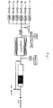
- Fig. 1 is a flow chart showing one example of a denitration rate measuring instrument used in the catalyst capability test in the example of the present invention.
- the honeycomb structure according to the present invention consists of a flat inorganic fiber sheet consisting of an inorganic fiber sheet having supported thereon zirconia as inorganic binder and zeolite, and a corrugated inorganic fiber sheet consisting of an inorganic fiber sheet having supported thereon the same inorganic binder and the same zeolite, which are alternately combined with each other, wherein the zeolite has a median particle diameter D50 of from 0.5 to 10.0 ⁇ m, and comprises bismuth (Bi) as denitration catalyst component, said bismuth denitration catalyst component being supported on said zeolite.
- Said zeolite preferably has a median particle diameter D50 of from 3.0 to 7.0 ⁇ m.
- the particle diameter of the zeolite herein means a particle diameter corresponding to 50% in the volume-based cumulative particle size distribution (i.e., a median particle diameter, D50) measured by a laser diffraction method.
- zeolite particles having a particle diameter (D50) of from 0.5 to 10.0 ⁇ m are used for ensuring the strength of the honeycomb structure.
- D50 particle diameter
- the contacts between the zeolite particles and the inorganic binders are decreased to make difficult the form retention.
- Zeolite particles having a small particle diameter that is less than the range described above are not practical due to the complexity in industrial production.
- the use of the zeolite particles having a particle diameter within the range described above increases the contacts to the inorganic binders, so as to ensure the strength suitable for the form retention.
- the flat inorganic fiber sheet consisting of an inorganic fiber sheet having supported thereon an inorganic binder and the zeolite, and the corrugated inorganic fiber sheet consisting of an inorganic fiber sheet having supported thereon the same inorganic binder and the zeolite are alternately combined with each other, so as to produce a honeycomb structure.
- the prescribed particle diameter (i.e., the median particle diameter, D50) of the zeolite commercially available zeolite may be used after pulverizing.
- the honeycomb structure means an integrated structure consisting of plural through holes (cells) partitioned with a partitioning wall, through which an exhaust gas is capable of passing, and the partitioning wall, and the cross sectional shape of the through holes described above(i.e., the cross sectional shape of the cells) is not particularly limited, examples of which include a circular shape, a circular arc shape, a square shape, a rectangular shape, and a hexagonal shape.
- the inorganic fiber sheet is preferably a glass fiber sheet or a ceramic fiber sheet.
- the inorganic binder is formed of zirconia.
- Another denitration catalyst not according to the present invention may be a catalyst for cleaning an exhaust gas (denitration catalyst) formed of small pieces of the substrate of the honeycomb structure (i.e., those formed only of the flat substrate or the corrugated substrate) or those in a pellet form.
- the small pieces of the substrate of the honeycomb structure have a corrugated form having one or more repeating concave grooves, they have small values for each of the width dimension per one of the concave groove (denoted by A), the repetition number in the width direction (denoted by n), the height dimension (denoted by B), and the depth dimension (denoted by C).
- the width dimension (A) is 2.0 mm or more, preferably 3.0 mm or more, and more preferably 4.0 mm or more.
- the width dimension (A) is preferably 100 mm or less, more preferably 50 mm or less, further preferably 25 mm or less, and still further preferably 10 mm or less.
- the height dimension (B) is 1.0 mm or more, preferably 2.0 mm or more, and more preferably 3.0 mm or more.
- the height dimension (B) is preferably 50 mm or less, more preferably 25 mm or less, and further preferably 10 mm or less.
- the repetition number in the width direction (n) is from 1 to 100, preferably from 1 to 10, more preferably from 1 to 5, and further preferably from 2 to 4.
- the depth dimension (C) is 3.0 mm or more, preferably 4.0 mm or more, and more preferably 5.0 mm or more.
- the depth dimension (C) is preferably 200 mm or less, more preferably 100 mm or less, further preferably 50.0 mm or less, still further preferably 20.0 mm or less, still further preferably 15.0 mm or less, and still further preferably 10.0 mm or less.
- the zeolite having the particular particle diameter described above, a solvent, and the inorganic binder are mixed to prepare a slurry.
- the slurry is coated on glass fiber paper as the inorganic fiber sheet.
- the zeolite is preferably MFI zeolite or FER zeolite, and the zeolite used may also be MOR zeolite, BEA zeolite, or the like.
- the inorganic binder used is zirconia.
- any known coating method may be used for coating, and examples thereof include a so-called dipping method, a brush coating method, a spray coating method, and a drop coating method.
- the slurry-coated glass fiber sheet is then shaped with a corrugating mold and a pressing jig, the corrugated slurry-coated glass fiber sheet thus shaped is dried under condition of from 100 to 200oC for from 1 to 2 hours and released from the mold, and separately the flat slurry-coated glass fiber sheet having not been shaped is dried under condition of from 100 to 200oC for from 1 to 2 hours.
- the inorganic binder added to the slurry functions as a binder between the glass fiber sheet and the zeolite, so as to enable retention of the corrugated form after shaping the glass fiber sheet.
- the corrugated slurry-coated glass fiber sheet and the flat slurry-coated glass fiber sheet are calcined under condition of from 300 to 550oC for from 1 to 4 hours.
- the corrugated glass fiber sheet substrate and the flat glass fiber sheet substrate thus obtained are then laminated alternately to provide the honeycomb structure.
- the honeycomb structure according to the present invention consists of a flat glass fiber sheet consisting of an inorganic fiber sheet having supported thereon the inorganic binder and zeolite, and a corrugated glass fiber sheet consisting of an inorganic fiber sheet having supported thereon the same inorganic binder and zeolite, which are alternately combined with each other, wherein it is characterized in that the zeolite has a particle diameter (i.e., a median particle diameter, D50) of from 0.5 to 10.0 ⁇ m.
- the use of the zeolite having the particular particle diameter described above can provide a honeycomb structure that has a sufficiently high strength, ensures the use in a state with high endurance property against the external factors, such as vibration, and is excellent in durability.
- the honeycomb structure useful as catalyst for cleaning an exhaust gas according to the present invention is characterized in that it contains a denitration catalyst component that is supported on the zeolite of the aforementioned honeycomb structure.
- the inorganic binder is zirconia.
- the catalyst for cleaning an exhaust gas contains, as the denitration catalyst component, a metallic element consisting of bismuth (Bi) on the zeolite.
- the precursor compound of the metallic element to be supported may be an inorganic acid salt (such as nitrate and chloride) or an organic acid salt (such as acetate).
- Any supporting method for the catalyst metal may be used as far as the denitration capability is exhibited, and examples thereof include an ion exchange method and an impregnation supporting method.
- the ion exchange method include such a method that zeolite is suspended in an aqueous solution containing a precursor compound of bismuth (Bi), and the zeolite having the catalyst metal bonded thereto through ion exchange is taken out from the aqueous solution, dried, and then calcined.
- the precursor compound of the metallic element to be supported may be an inorganic acid salt (such as nitrate and chloride), an organic acid salt (such as acetate), or an oxide.
- Any supporting method for the catalyst metal may be used as far as the denitration capability is exhibited, and examples thereof include an ion exchange method and an impregnation supporting method. Examples of the ion exchange method include such a method that zeolite having the catalyst metal bonded thereto through ion exchange is taken out from the solvent, dried, and then calcined.
- the solvent for dissolving the aforementioned precursor compound of bismuth is a compound having two or more hydroxy groups per molecule.
- the compound having two or more hydroxy groups per molecule used is preferably ethylene glycol.
- a compound having two or more hydroxy groups per molecule such as a diol compound, is used as the solvent, and thus it has such a feature that bismuth is present in the form of ion in the catalyst slurry.
- bismuth is uniformly supported on the zeolite.
- the use of the zeolite having the particular particle diameter described above can provide the catalyst for cleaning an exhaust gas using the honeycomb structure that has a sufficiently high strength, ensures the use in a state with high endurance property against the external factors, such as vibration, and is excellent in durability.
- a nitrogen oxide can be effectively decreased from a combustion exhaust gas having a high concentration of a nitrogen oxide (NOx) and a sulfur oxide (SOx) present therein, and having a low exhaust gas temperature of 300oC or less, discharged, for example, from a marine vessel engine, i.e., a large marine vessel diesel engine, a large scale boiler for a factory, an electric power plant, a community central heating and air-conditioning plant, and the like.
- a marine vessel engine i.e., a large marine vessel diesel engine, a large scale boiler for a factory, an electric power plant, a community central heating and air-conditioning plant, and the like.
- the step of supporting may be performed as a separate step after producing the honeycomb structure from glass paper
- the step of supporting may be performed in the course of from the glass paper to the honeycomb structure, or may be performed simultaneously with the preparation of the substrate of the honeycomb structure by mixing the aforementioned bismuth solution with the slurry formed of the zeolite, the solvent, and the inorganic binder.
- the reducing agent is not particularly limited as far as it has a reducing power at the temperature where the combustion exhaust gas is reduced, and methanol or ethanol, as an alcohol having a small number of carbon, is preferably used.
- FER zeolite having a particle diameter (D50) of 7.0 ⁇ m (CP914C, a trade name, produced by Zeolyst International) was used, and 25 g of the zeolite, 18.75 g of ion exchanged water, and 11.5 g of an aqueous solution of a silica sol (solid concentration: 22.0% by weight) as an inorganic binder were mixed to provide a slurry. 18 g of the slurry was coated on glass paper of 100 mm ⁇ 150 mm to provide flat slurry-coated glass paper, and then the flat slurry-coated glass paper was dried at 110oC for 1 hour.
- D50 particle diameter
- CP914C a trade name, produced by Zeolyst International
- the particle diameter of the zeolite herein is a particle diameter corresponding to 50% in the volume-based cumulative particle size distribution (i.e., a median particle diameter, D50) measured by a laser diffraction method, and the particle diameter (D50) of the zeolite was measured with a laser diffraction and scattering particle size analyzer (Microtrac MT3300EXII, a trade name, produced by Nikkiso Co., Ltd.).
- a honeycomb structure was produced in the same manner as in Example 1 described above provided that the difference from Example 1 described above was that FER zeolite having a particle diameter (D50) of 3.0 ⁇ m was used.
- a honeycomb structure was produced in the same manner as in Example 1 described above provided that the difference from Example 1 described above was that MFI zeolite having a particle diameter (D50) of 6.0 ⁇ m was used.
- Example 1 For comparison, a honeycomb structure was produced in the same manner as in Example 1 described above provided that the difference from Example 1 described above was that FER zeolite having a particle diameter (D50) of 36.0 ⁇ m was used.
- Example 1 For comparison, a honeycomb structure was produced in the same manner as in Example 1 described above provided that the difference from Example 1 described above was that FER zeolite having a particle diameter (D50) of 14.0 ⁇ m was used.
- honeycomb structures obtained in Examples 1 to 3 and Comparative Examples 1 and 2 were evaluated by visually observing for the strength of the honeycomb structures, and the results obtained are shown in Table 1 below.
- the evaluation standard is as follows.
- honeycomb structure that has a sufficiently high strength, ensures the use in a state with high endurance property against the external factors, such as vibration, and is excellent in durability can be obtained by using zeolite having the particular particle diameter.
- a denitration catalyst for cleaning an exhaust gas using a honeycomb structure according to the present invention was produced in the following manner.
- FER zeolite having a particle diameter (D50) of 7.0 ⁇ m (CP914C, a trade name, produced by Zeolyst International) was used, and 20 g of the zeolite, 9.2 g of a zirconia sol (Zircosol 20A, a trade name, produced by Daiichi Kigenso Kagaku Kogyo Co., Ltd.) as an inorganic binder, 2.65 g of bismuth nitrate (Bismuth(III) Nitrate Pentahydrate, a trade name, produced by Kishida Chemical Co., Ltd.), and 20 g of ion exchanged water were mixed and agitated at room temperature for 1 hour to provide a slurry having a solid concentration of 46.8% by weight.
- the slurry was coated on glass paper of 100 mm ⁇ 150 mm to provide flat slurry-coated glass paper, and then the flat slurry-coated glass paper was dried at 110oC for 1 hour.
- the slurry described above was coated on glass paper of 100 mm ⁇ 230 mm, the slurry-coated glass paper was shaped with a corrugating mold and a pressing jig, the corrugated slurry-coated glass paper thus shaped is dried at 110oC for 1 hour, and released from the mold.
- the flat slurry-coated glass paper and the corrugated slurry-coated glass paper were calcined at a temperature of 500oC for 3 hours, thereby providing flat glass paper having supported thereon the zeolite, bismuth (Bi) as the denitration catalyst metal, and the zirconium compound as the shape maintaining binder, and corrugated glass paper having supported thereon the same materials.
- Two plies of the flat catalyst-supported glass paper and one ply of the corrugated catalyst-supported glass paper were combined alternately, thereby producing a denitration catalyst for cleaning a combustion exhaust gas using the honeycomb structure.
- a denitration catalyst for cleaning a combustion exhaust gas using a honeycomb structure was produced in the same manner as in Example 4 described above provided that the difference from Example 4 described above was that an aqueous solution containing an alumina sol (Aluminasol 520, a trade name, produced by Nissan Chemical Industries, Ltd.) as the inorganic binder was used instead of the zirconia sol (Zircosol 20A) as the inorganic binder.
- an aqueous solution containing an alumina sol Alluminasol 520, a trade name, produced by Nissan Chemical Industries, Ltd.
- a denitration catalyst for cleaning a combustion exhaust gas using a honeycomb structure was produced in the same manner as in Example 4 described above provided that the difference from Example 4 described above was that an aqueous solution containing a silica sol (Silicadol 20A, a trade name, produced by Nippon Chemical Industrial Co., Ltd.) as the inorganic binder was used instead of the zirconia sol (Zircosol 20A) as the inorganic binder.
- a silica sol Silicadol 20A, a trade name, produced by Nippon Chemical Industrial Co., Ltd.
- a denitration catalyst for cleaning a combustion exhaust gas using a honeycomb structure was produced in the same manner as in Example 4 described above provided that the difference from Example 4 described above was that an aqueous solution containing a titania sol (Titaniasol S-300A, a trade name, produced by Millennium Inorganic Chemicals, Inc.) as the inorganic binder was used instead of the zirconia sol (Zircosol 20A) as the inorganic binder.
- a titania sol Tianiasol S-300A, a trade name, produced by Millennium Inorganic Chemicals, Inc.
- Example 4 The honeycomb structures obtained in Example 4 according to the invention and Example 5 (not according to the invention) and Reference Examples 1 and 2 were evaluated by visually observing for the strength of the honeycomb structures based on the aforementioned evaluation standard, and the results obtained are shown in Table 4 below.
- Fig. 1 shows a flow chart of a capability evaluation test instrument for a denitration catalyst.
- the denitration catalyst for cleaning a combustion exhaust gas using the honeycomb structure was charged in a denitration reactor formed of a stainless steel reaction tube, and subjected to a capability evaluation test for an exhaust gas having an NO concentration of 1,000 ppm under the test condition shown in Table 2 below using methanol as a reducing agent in a concentration of 1,800 ppm.
- Table 2 Denitration capability evaluation test condition Gas composition: NO 1,000 ppmvd Gas composition: air balance Reducing agent: methanol 1,800 ppmvd Water content 5% by volume Space velocity (SV) 7,440 Reaction temperature 250oC
- the gas at the outlet port of the denitration reactor was measured for the concentration of nitrogen oxide (NOx) at the outlet port with an NOx meter.
- the denitration rate as the NOx removal capability of the catalyst was calculated from the measured value with the NOx meter according to the following expression (1).
- Denitration rate % NOxin ⁇ NOxout / NOxin ⁇ 100
- Example 4 being according to the invention, were able to decrease effectively a nitrogen oxide even in the presence of a sulfur oxide (SOx) in a high concentration, the denitration catalysts were tested for the durability to sulfur trioxide as a sulfur oxide (SOx).
- SOx sulfur oxide
- a durability test was performed in such a manner that the denitration catalysts for cleaning a combustion exhaust gas using the honeycomb structures obtained in Examples 4 and 5 (Example 4 being according to the invention) and Reference Examples 1 and 2 were exposed to a gas containing sulfur oxides (SO 2 and SO 3 ) for 6 hours under the condition shown in Table 3 below.
- the sulfur oxides (SO 2 and SO 3 ) were sent to the evaporator with a metering pump, and then fed to the reaction tube after gasification in the evaporator.
- the capability evaluation test corresponding to the cleaning method of a combustion exhaust gas was performed in the same manner as above by using the denitration catalysts after exposing to sulfur oxides (SO 2 and SO 3 ).
- the results of the evaluation test of the denitration catalyst capability thus obtained are shown in Table 4 below.
- a nitrogen oxide can be effectively decreased from a combustion exhaust gas having a high concentration of a nitrogen oxide (NOx) and a sulfur oxide (SOx) present therein, and having a low exhaust gas temperature of 300oC or less, discharged, for example, from a marine vessel engine, i.e., a large marine vessel diesel engine, a large scale boiler for a factory, an electric power plant, a community central heating and air-conditioning plant, and the like.
- a marine vessel engine i.e., a large marine vessel diesel engine, a large scale boiler for a factory, an electric power plant, a community central heating and air-conditioning plant, and the like.
- Bismuth nitrate (Bismuth(III) Nitrate Pentahydrate, a trade name, produced by Kishida Chemical Co., Ltd.) was dissolved in ethylene glycol (Ethylene Glycol, a trade name, produced by Kishida Chemical Co., Ltd.), to which FER zeolite having a particle diameter (D50) of 7.0 ⁇ m (CP914C, a trade name, produced by Zeolyst International) was added to provide a slurry.
- ethylene glycol Ethylene Glycol, a trade name, produced by Kishida Chemical Co., Ltd.
- FER zeolite having a particle diameter (D50) of 7.0 ⁇ m CP914C, a trade name, produced by Zeolyst International
- the slurry was agitated at 60oC for 3 hours, and after cooling to room temperature, a zirconia sol (Zircosol AC-20, a trade name, produced by Daiichi Kigenso Kagaku Kogyo Co., Ltd.) as an inorganic binder was added thereto.
- a zirconia sol Zircosol AC-20, a trade name, produced by Daiichi Kigenso Kagaku Kogyo Co., Ltd.
- 18 g of the catalyst slurry was coated on glass fiber paper cut into 100 mm ⁇ 150 mm to provide flat slurry-coated glass paper, and then the flat slurry-coated glass paper was dried at 110oC for 1 hour.
- a denitration catalyst for cleaning a combustion exhaust gas using a honeycomb structure according to the present invention was produced in the same manner as in Example 6 provided that the difference from Example 6 described above was that ion exchanged water was used instead of ethylene glycol.
- Example 6 The supported amounts of bismuth on the both surfaces of the flat glass fiber sheets of the honeycomb structures obtained in Example 6 according to the present invention and Reference Example 3 were measured with a fluorescent X-ray analyzer, and the results obtained are shown in Table 5 below. Table 5 Results of measurement of surface bismuth amount (% by weight) Example 6 Reference Example 3 Front surface 5.14 2.70 Back surface 5.48 4.78
- the denitration catalysts for cleaning a combustion exhaust gas using the honeycomb structures of Example 6 according to the present invention and Reference Example 3 they were subjected to a denitration capability evaluation test under the condition shown in Table 6, and then tested for the durability to a sulfur oxide (SOx) for 250 hours under the condition shown in Table 7. Thereafter, the denitration catalysts after exposing to sulfur oxides (SO 2 and SO 3 ) were again subjected to a denitration capability evaluation test under the condition shown in Table 6.
Claims (3)
- Eine Wabenstruktur, bestehend aus
einem flachen Blatt aus anorganischer Faser, bestehend aus einem anorganischen Faserblatt mit darauf geträgertem Zirkonoxid als anorganisches Bindemittel sowie Zeolith, und
einem gewellten Blatt aus anorganischer Faser, bestehend aus einem Blatt aus anorganischer Faser mit darauf geträgertem gleichen anorganischen Bindemittel und dem gleichen Zeolith,
welche abwechselnd miteinander kombiniert sind,
wobei das Zeolith eine mittleren Teilchendurchmesser D50, gemessen mittels eines Laserdiffraktionverfahrens als 50% volumenbasierte kumulative Teilchengrößenverteilung, von 0,5 bis 10,0 µm aufweist und Bismut (Bi) als Denitrierungs-Katalysatorkomponente umfasst, wobei die Bismut Denitrierungs Katalysatorkomponente auf dem Zeolith geträgert ist - Die Wabenstruktur gemäß Anspruch 1, welche dadurch charakterisiert ist dass sowohl das flache anorganische Blatt als auch das gewellte Blatt aus anorganischer Faser ein Glasfaserblatt ist.
- Ein Verfahren zur Herstellung der Wabenstruktur gemäß Anspruch 1, umfassend den Schritt des Trägems von Bismut (Bi) als Denitrierungs-Katalysatorkomponente auf dem Zeolith,
wobei in dem Schritt Bismut (Bi) in einem Lösungsmittel gelöst ist, wobei das verwendete Lösungsmittel eine Verbindung mit zwei oder mehr Hydroxygruppen pro Molekül ist.
Priority Applications (1)
| Application Number | Priority Date | Filing Date | Title |
|---|---|---|---|
| EP19170422.0A EP3542900A1 (de) | 2014-03-27 | 2015-03-27 | Katalysator zur reinigung von abgas mithilfe einer wabenstruktur |
Applications Claiming Priority (2)
| Application Number | Priority Date | Filing Date | Title |
|---|---|---|---|
| JP2014065986 | 2014-03-27 | ||
| PCT/JP2015/059606 WO2015147257A1 (ja) | 2014-03-27 | 2015-03-27 | ハニカム構造体、およびこれを用いた排ガス浄化用触媒、並びに排ガス浄化用触媒の製造方法 |
Related Child Applications (1)
| Application Number | Title | Priority Date | Filing Date |
|---|---|---|---|
| EP19170422.0A Division EP3542900A1 (de) | 2014-03-27 | 2015-03-27 | Katalysator zur reinigung von abgas mithilfe einer wabenstruktur |
Publications (3)
| Publication Number | Publication Date |
|---|---|
| EP3124115A1 EP3124115A1 (de) | 2017-02-01 |
| EP3124115A4 EP3124115A4 (de) | 2017-10-25 |
| EP3124115B1 true EP3124115B1 (de) | 2019-05-15 |
Family
ID=54195761
Family Applications (2)
| Application Number | Title | Priority Date | Filing Date |
|---|---|---|---|
| EP19170422.0A Withdrawn EP3542900A1 (de) | 2014-03-27 | 2015-03-27 | Katalysator zur reinigung von abgas mithilfe einer wabenstruktur |
| EP15768958.9A Active EP3124115B1 (de) | 2014-03-27 | 2015-03-27 | Wabenstruktur zur verwendung als abgasreinigungskatalysator sowie verfahren zu seiner herstellung |
Family Applications Before (1)
| Application Number | Title | Priority Date | Filing Date |
|---|---|---|---|
| EP19170422.0A Withdrawn EP3542900A1 (de) | 2014-03-27 | 2015-03-27 | Katalysator zur reinigung von abgas mithilfe einer wabenstruktur |
Country Status (7)
| Country | Link |
|---|---|
| US (2) | US20170106356A1 (de) |
| EP (2) | EP3542900A1 (de) |
| JP (1) | JP6663842B2 (de) |
| KR (1) | KR102375936B1 (de) |
| CN (1) | CN106132540B (de) |
| DK (1) | DK3124115T3 (de) |
| WO (1) | WO2015147257A1 (de) |
Families Citing this family (11)
| Publication number | Priority date | Publication date | Assignee | Title |
|---|---|---|---|---|
| JP6574591B2 (ja) * | 2015-03-31 | 2019-09-11 | 日立造船株式会社 | 触媒処理装置およびその製造方法 |
| JP2018192376A (ja) * | 2015-10-02 | 2018-12-06 | 日立造船株式会社 | 排ガス浄化用触媒およびその製造方法 |
| JP6886776B2 (ja) * | 2016-03-31 | 2021-06-16 | 日立造船株式会社 | 排ガス浄化触媒 |
| KR101952314B1 (ko) * | 2017-03-29 | 2019-02-27 | 주식회사 나노 | 적층형 육각형상 선택적촉매환원 촉매 카트리지 제조방법 및 이를 이용한 촉매 담체 |
| CN113164923B (zh) * | 2018-12-27 | 2024-04-19 | 优美科触媒日本有限公司 | 废气净化用催化剂和废气净化方法 |
| CN113316484A (zh) * | 2019-01-15 | 2021-08-27 | 日立造船株式会社 | 废气净化用催化剂 |
| WO2020149315A1 (ja) | 2019-01-15 | 2020-07-23 | 日立造船株式会社 | 排ガス浄化用触媒および排ガス浄化用触媒の製造方法 |
| EP3689441A1 (de) * | 2019-02-01 | 2020-08-05 | Casale Sa | Verfahren zur entfernung von stickoxiden aus einem gas |
| CN110508318A (zh) * | 2019-10-22 | 2019-11-29 | 山东国瓷功能材料股份有限公司 | 一种复合脱硝催化剂及其制备方法和应用 |
| CN114206495B (zh) * | 2019-12-13 | 2023-05-23 | 南开大学 | 脱硝催化剂及使用该催化剂的脱硝方法 |
| CN112138727A (zh) * | 2020-09-24 | 2020-12-29 | 江西博鑫精陶环保科技有限公司 | 一种无机纤维蜂窝载体及其制备方法 |
Family Cites Families (20)
| Publication number | Priority date | Publication date | Assignee | Title |
|---|---|---|---|---|
| US4170629A (en) * | 1975-09-15 | 1979-10-09 | Betz Erwin C | Method of converting hydrocarbon waste gas streams using a non-uniform crimped metal ribbon packed catalyst bed |
| JP2854321B2 (ja) * | 1989-05-22 | 1999-02-03 | バブコツク日立株式会社 | 窒素酸化物除去用板状触媒の製造方法 |
| US5055029A (en) * | 1990-01-22 | 1991-10-08 | Mobil Oil Corporation | Reducing NOx emissions from a circulating fluid bed combustor |
| JP2925122B2 (ja) * | 1990-12-17 | 1999-07-28 | 株式会社西部技研 | ハニカム状セラミツクス触媒担体の製造法 |
| DE4200995C2 (de) * | 1991-01-21 | 2002-02-14 | Seibu Giken Fukuoka Kk | Verfahren zur Herstellung eines wabenförmigen Gasadsorptionselements oder eines wabenförmigen Katalysatorträgers |
| JPH07124475A (ja) * | 1993-11-05 | 1995-05-16 | Idemitsu Kosan Co Ltd | 排気ガス浄化用触媒 |
| JPH0811251A (ja) * | 1994-06-30 | 1996-01-16 | Nippon Muki Co Ltd | ハニカムエレメント及びその製造方法 |
| JP2981714B2 (ja) * | 1995-03-29 | 1999-11-22 | ニチアス株式会社 | 脱臭フィルター |
| JPH11188238A (ja) | 1997-12-26 | 1999-07-13 | Meidensha Corp | 脱硝方法 |
| JPH11290693A (ja) * | 1998-04-10 | 1999-10-26 | Daikin Ind Ltd | 空気浄化触媒、該空気浄化触媒の製造方法、該空気浄化触媒を用いた触媒構造体及び該触媒構造体を備えた空気調和機 |
| US20030165638A1 (en) * | 2001-07-06 | 2003-09-04 | Louks John W. | Inorganic fiber substrates for exhaust systems and methods of making same |
| MXPA04000118A (es) * | 2001-07-06 | 2004-06-03 | 3M Innovative Properties Co | Sustratos de fibras inorganicas para sistemas de escape y metodos de fabricacion de los mismos. |
| JP2004261754A (ja) | 2003-03-04 | 2004-09-24 | Sumitomo Metal Mining Co Ltd | 排ガス浄化触媒及び浄化方法 |
| JP2004358454A (ja) | 2003-04-11 | 2004-12-24 | Sumitomo Metal Mining Co Ltd | 排ガス浄化触媒及び浄化方法 |
| JP2006239917A (ja) * | 2005-03-01 | 2006-09-14 | Matsushita Electric Ind Co Ltd | ハニカム構造体とその製造法 |
| WO2006092986A1 (ja) * | 2005-03-02 | 2006-09-08 | Ibiden Co., Ltd. | 無機繊維集合体、無機繊維集合体の製造方法、ハニカム構造体及びハニカム構造体の製造方法 |
| US20090286678A1 (en) * | 2005-05-02 | 2009-11-19 | Symyx Technologies, Inc. | High Surface Area Metal And Metal Oxide Materials and Methods of Making the Same |
| JP5921252B2 (ja) * | 2012-02-22 | 2016-05-24 | 日立造船株式会社 | 排ガス脱硝装置における触媒担持ハニカム構造体の端部処理方法 |
| JP6051084B2 (ja) | 2012-03-30 | 2016-12-21 | 日立造船株式会社 | 燃焼排ガスの浄化方法、および脱硝触媒 |
| WO2015119069A1 (ja) * | 2014-02-07 | 2015-08-13 | 日立造船株式会社 | 燃焼排ガス浄化用触媒、および燃焼排ガスの浄化方法 |
-
2015
- 2015-03-27 EP EP19170422.0A patent/EP3542900A1/de not_active Withdrawn
- 2015-03-27 US US15/129,497 patent/US20170106356A1/en not_active Abandoned
- 2015-03-27 KR KR1020167024464A patent/KR102375936B1/ko active IP Right Grant
- 2015-03-27 JP JP2016510550A patent/JP6663842B2/ja active Active
- 2015-03-27 WO PCT/JP2015/059606 patent/WO2015147257A1/ja active Application Filing
- 2015-03-27 DK DK15768958.9T patent/DK3124115T3/da active
- 2015-03-27 EP EP15768958.9A patent/EP3124115B1/de active Active
- 2015-03-27 CN CN201580016803.9A patent/CN106132540B/zh active Active
-
2018
- 2018-08-03 US US16/054,146 patent/US10946366B2/en active Active
Non-Patent Citations (1)
| Title |
|---|
| None * |
Also Published As
| Publication number | Publication date |
|---|---|
| US10946366B2 (en) | 2021-03-16 |
| JPWO2015147257A1 (ja) | 2017-04-13 |
| EP3124115A4 (de) | 2017-10-25 |
| US20180345258A1 (en) | 2018-12-06 |
| US20170106356A1 (en) | 2017-04-20 |
| EP3124115A1 (de) | 2017-02-01 |
| EP3542900A1 (de) | 2019-09-25 |
| DK3124115T3 (da) | 2019-08-05 |
| KR102375936B1 (ko) | 2022-03-16 |
| JP6663842B2 (ja) | 2020-03-13 |
| CN106132540A (zh) | 2016-11-16 |
| KR20160140610A (ko) | 2016-12-07 |
| WO2015147257A1 (ja) | 2015-10-01 |
| CN106132540B (zh) | 2020-03-17 |
Similar Documents
| Publication | Publication Date | Title |
|---|---|---|
| EP3124115B1 (de) | Wabenstruktur zur verwendung als abgasreinigungskatalysator sowie verfahren zu seiner herstellung | |
| EP3096876B1 (de) | Methode zur herstellung eines katalytischen vollextrudates im form von wabenkorb | |
| EP3103550A1 (de) | Katalysator und verfahren zur reinigung von verbrennungsabgasen | |
| KR20110086720A (ko) | 선택적 암모니아 산화를 위한 이금속 촉매 | |
| US11701615B2 (en) | Exhaust gas purifying catalyst | |
| EP2593212B2 (de) | Kupfer-enthaltendes zsm-34-, off- oder eri-zeolith-material für selektive nox-reduzierung | |
| US20190193054A1 (en) | Denitration catalyst and method for producing same | |
| JP2014501612A (ja) | 窒素含有化合物の変換方法 | |
| JP5384368B2 (ja) | アンモニア分解触媒および該触媒によるアンモニア含有排ガスの処理方法 | |
| JP5987855B2 (ja) | 排ガス浄化用触媒 | |
| Szymaszek-Wawryca et al. | Catalytic Performance and Sulfur Dioxide Resistance of One-Pot Synthesized Fe-MCM-22 in Selective Catalytic Reduction of Nitrogen Oxides with Ammonia (NH3-SCR)—The Effect of Iron Content | |
| WO2020085168A1 (ja) | Cu-P共担持ゼオライトの製造方法、これに用いることが可能な触媒前駆体組成物及び処理液、並びに積層触媒の製造方法 | |
| EP3466879A1 (de) | Chabazitzeolith mit hoher hydrothermaler beständigkeit und verfahren zur herstellung davon | |
| WO2022188808A1 (en) | Catalytic article comprising vanadium-based catalyst and molecular sieve-based catalyst | |
| JP2018038978A (ja) | Scr触媒 | |
| WO2018221194A1 (ja) | Cha型アルミノ珪酸塩及びその製造方法、並びに、これらを用いた排ガス浄化用触媒、排ガス浄化装置及び排ガスの浄化方法 | |
| WO2017057736A1 (ja) | 排ガス浄化用触媒およびその製造方法 | |
| EP4019127A1 (de) | Flouridhaltige feinporige zeolithzusammensetzungen | |
| US20170001181A1 (en) | Catalyst for purifying combustion exhaust gas, and method for purifying combustion exhaust gas | |
| EP4265329A1 (de) | Al-p-verbundoxid und abgasreinigungskatalysator damit | |
| JP2023045081A (ja) | 排ガス浄化触媒装置 | |
| CN114929367A (zh) | 耐久性铜scr催化剂 | |
| WO2024008077A1 (en) | Catalytic article comprising ammonia oxidation catalyst |
Legal Events
| Date | Code | Title | Description |
|---|---|---|---|
| STAA | Information on the status of an ep patent application or granted ep patent |
Free format text: STATUS: THE INTERNATIONAL PUBLICATION HAS BEEN MADE |
|
| PUAI | Public reference made under article 153(3) epc to a published international application that has entered the european phase |
Free format text: ORIGINAL CODE: 0009012 |
|
| STAA | Information on the status of an ep patent application or granted ep patent |
Free format text: STATUS: REQUEST FOR EXAMINATION WAS MADE |
|
| 17P | Request for examination filed |
Effective date: 20161010 |
|
| AK | Designated contracting states |
Kind code of ref document: A1 Designated state(s): AL AT BE BG CH CY CZ DE DK EE ES FI FR GB GR HR HU IE IS IT LI LT LU LV MC MK MT NL NO PL PT RO RS SE SI SK SM TR |
|
| AX | Request for extension of the european patent |
Extension state: BA ME |
|
| DAV | Request for validation of the european patent (deleted) | ||
| DAX | Request for extension of the european patent (deleted) | ||
| RIC1 | Information provided on ipc code assigned before grant |
Ipc: F01N 3/10 20060101ALI20170913BHEP Ipc: B01J 29/69 20060101ALI20170913BHEP Ipc: B01J 35/04 20060101AFI20170913BHEP Ipc: B01D 53/86 20060101ALI20170913BHEP |
|
| A4 | Supplementary search report drawn up and despatched |
Effective date: 20170921 |
|
| GRAP | Despatch of communication of intention to grant a patent |
Free format text: ORIGINAL CODE: EPIDOSNIGR1 |
|
| STAA | Information on the status of an ep patent application or granted ep patent |
Free format text: STATUS: GRANT OF PATENT IS INTENDED |
|
| INTG | Intention to grant announced |
Effective date: 20181204 |
|
| GRAS | Grant fee paid |
Free format text: ORIGINAL CODE: EPIDOSNIGR3 |
|
| GRAA | (expected) grant |
Free format text: ORIGINAL CODE: 0009210 |
|
| STAA | Information on the status of an ep patent application or granted ep patent |
Free format text: STATUS: THE PATENT HAS BEEN GRANTED |
|
| AK | Designated contracting states |
Kind code of ref document: B1 Designated state(s): AL AT BE BG CH CY CZ DE DK EE ES FI FR GB GR HR HU IE IS IT LI LT LU LV MC MK MT NL NO PL PT RO RS SE SI SK SM TR |
|
| REG | Reference to a national code |
Ref country code: CH Ref legal event code: EP |
|
| REG | Reference to a national code |
Ref country code: DE Ref legal event code: R096 Ref document number: 602015030402 Country of ref document: DE |
|
| REG | Reference to a national code |
Ref country code: IE Ref legal event code: FG4D |
|
| REG | Reference to a national code |
Ref country code: DK Ref legal event code: T3 Effective date: 20190731 |
|
| REG | Reference to a national code |
Ref country code: CH Ref legal event code: NV Representative=s name: LLR, CH |
|
| REG | Reference to a national code |
Ref country code: NL Ref legal event code: MP Effective date: 20190515 |
|
| REG | Reference to a national code |
Ref country code: LT Ref legal event code: MG4D |
|
| PG25 | Lapsed in a contracting state [announced via postgrant information from national office to epo] |
Ref country code: AL Free format text: LAPSE BECAUSE OF FAILURE TO SUBMIT A TRANSLATION OF THE DESCRIPTION OR TO PAY THE FEE WITHIN THE PRESCRIBED TIME-LIMIT Effective date: 20190515 Ref country code: PT Free format text: LAPSE BECAUSE OF FAILURE TO SUBMIT A TRANSLATION OF THE DESCRIPTION OR TO PAY THE FEE WITHIN THE PRESCRIBED TIME-LIMIT Effective date: 20190915 Ref country code: ES Free format text: LAPSE BECAUSE OF FAILURE TO SUBMIT A TRANSLATION OF THE DESCRIPTION OR TO PAY THE FEE WITHIN THE PRESCRIBED TIME-LIMIT Effective date: 20190515 Ref country code: SE Free format text: LAPSE BECAUSE OF FAILURE TO SUBMIT A TRANSLATION OF THE DESCRIPTION OR TO PAY THE FEE WITHIN THE PRESCRIBED TIME-LIMIT Effective date: 20190515 Ref country code: HR Free format text: LAPSE BECAUSE OF FAILURE TO SUBMIT A TRANSLATION OF THE DESCRIPTION OR TO PAY THE FEE WITHIN THE PRESCRIBED TIME-LIMIT Effective date: 20190515 Ref country code: NO Free format text: LAPSE BECAUSE OF FAILURE TO SUBMIT A TRANSLATION OF THE DESCRIPTION OR TO PAY THE FEE WITHIN THE PRESCRIBED TIME-LIMIT Effective date: 20190815 Ref country code: LT Free format text: LAPSE BECAUSE OF FAILURE TO SUBMIT A TRANSLATION OF THE DESCRIPTION OR TO PAY THE FEE WITHIN THE PRESCRIBED TIME-LIMIT Effective date: 20190515 Ref country code: FI Free format text: LAPSE BECAUSE OF FAILURE TO SUBMIT A TRANSLATION OF THE DESCRIPTION OR TO PAY THE FEE WITHIN THE PRESCRIBED TIME-LIMIT Effective date: 20190515 Ref country code: NL Free format text: LAPSE BECAUSE OF FAILURE TO SUBMIT A TRANSLATION OF THE DESCRIPTION OR TO PAY THE FEE WITHIN THE PRESCRIBED TIME-LIMIT Effective date: 20190515 |
|
| PG25 | Lapsed in a contracting state [announced via postgrant information from national office to epo] |
Ref country code: RS Free format text: LAPSE BECAUSE OF FAILURE TO SUBMIT A TRANSLATION OF THE DESCRIPTION OR TO PAY THE FEE WITHIN THE PRESCRIBED TIME-LIMIT Effective date: 20190515 Ref country code: LV Free format text: LAPSE BECAUSE OF FAILURE TO SUBMIT A TRANSLATION OF THE DESCRIPTION OR TO PAY THE FEE WITHIN THE PRESCRIBED TIME-LIMIT Effective date: 20190515 Ref country code: BG Free format text: LAPSE BECAUSE OF FAILURE TO SUBMIT A TRANSLATION OF THE DESCRIPTION OR TO PAY THE FEE WITHIN THE PRESCRIBED TIME-LIMIT Effective date: 20190815 Ref country code: GR Free format text: LAPSE BECAUSE OF FAILURE TO SUBMIT A TRANSLATION OF THE DESCRIPTION OR TO PAY THE FEE WITHIN THE PRESCRIBED TIME-LIMIT Effective date: 20190816 |
|
| REG | Reference to a national code |
Ref country code: AT Ref legal event code: MK05 Ref document number: 1132805 Country of ref document: AT Kind code of ref document: T Effective date: 20190515 |
|
| PG25 | Lapsed in a contracting state [announced via postgrant information from national office to epo] |
Ref country code: AT Free format text: LAPSE BECAUSE OF FAILURE TO SUBMIT A TRANSLATION OF THE DESCRIPTION OR TO PAY THE FEE WITHIN THE PRESCRIBED TIME-LIMIT Effective date: 20190515 Ref country code: SK Free format text: LAPSE BECAUSE OF FAILURE TO SUBMIT A TRANSLATION OF THE DESCRIPTION OR TO PAY THE FEE WITHIN THE PRESCRIBED TIME-LIMIT Effective date: 20190515 Ref country code: EE Free format text: LAPSE BECAUSE OF FAILURE TO SUBMIT A TRANSLATION OF THE DESCRIPTION OR TO PAY THE FEE WITHIN THE PRESCRIBED TIME-LIMIT Effective date: 20190515 Ref country code: CZ Free format text: LAPSE BECAUSE OF FAILURE TO SUBMIT A TRANSLATION OF THE DESCRIPTION OR TO PAY THE FEE WITHIN THE PRESCRIBED TIME-LIMIT Effective date: 20190515 |
|
| REG | Reference to a national code |
Ref country code: DE Ref legal event code: R097 Ref document number: 602015030402 Country of ref document: DE |
|
| PG25 | Lapsed in a contracting state [announced via postgrant information from national office to epo] |
Ref country code: SM Free format text: LAPSE BECAUSE OF FAILURE TO SUBMIT A TRANSLATION OF THE DESCRIPTION OR TO PAY THE FEE WITHIN THE PRESCRIBED TIME-LIMIT Effective date: 20190515 Ref country code: IT Free format text: LAPSE BECAUSE OF FAILURE TO SUBMIT A TRANSLATION OF THE DESCRIPTION OR TO PAY THE FEE WITHIN THE PRESCRIBED TIME-LIMIT Effective date: 20190515 |
|
| PLBE | No opposition filed within time limit |
Free format text: ORIGINAL CODE: 0009261 |
|
| STAA | Information on the status of an ep patent application or granted ep patent |
Free format text: STATUS: NO OPPOSITION FILED WITHIN TIME LIMIT |
|
| PG25 | Lapsed in a contracting state [announced via postgrant information from national office to epo] |
Ref country code: TR Free format text: LAPSE BECAUSE OF FAILURE TO SUBMIT A TRANSLATION OF THE DESCRIPTION OR TO PAY THE FEE WITHIN THE PRESCRIBED TIME-LIMIT Effective date: 20190515 |
|
| 26N | No opposition filed |
Effective date: 20200218 |
|
| PG25 | Lapsed in a contracting state [announced via postgrant information from national office to epo] |
Ref country code: PL Free format text: LAPSE BECAUSE OF FAILURE TO SUBMIT A TRANSLATION OF THE DESCRIPTION OR TO PAY THE FEE WITHIN THE PRESCRIBED TIME-LIMIT Effective date: 20190515 |
|
| PG25 | Lapsed in a contracting state [announced via postgrant information from national office to epo] |
Ref country code: SI Free format text: LAPSE BECAUSE OF FAILURE TO SUBMIT A TRANSLATION OF THE DESCRIPTION OR TO PAY THE FEE WITHIN THE PRESCRIBED TIME-LIMIT Effective date: 20190515 |
|
| PG25 | Lapsed in a contracting state [announced via postgrant information from national office to epo] |
Ref country code: MC Free format text: LAPSE BECAUSE OF FAILURE TO SUBMIT A TRANSLATION OF THE DESCRIPTION OR TO PAY THE FEE WITHIN THE PRESCRIBED TIME-LIMIT Effective date: 20190515 |
|
| REG | Reference to a national code |
Ref country code: BE Ref legal event code: MM Effective date: 20200331 |
|
| PG25 | Lapsed in a contracting state [announced via postgrant information from national office to epo] |
Ref country code: LU Free format text: LAPSE BECAUSE OF NON-PAYMENT OF DUE FEES Effective date: 20200327 |
|
| PG25 | Lapsed in a contracting state [announced via postgrant information from national office to epo] |
Ref country code: IE Free format text: LAPSE BECAUSE OF NON-PAYMENT OF DUE FEES Effective date: 20200327 Ref country code: FR Free format text: LAPSE BECAUSE OF NON-PAYMENT OF DUE FEES Effective date: 20200331 |
|
| PG25 | Lapsed in a contracting state [announced via postgrant information from national office to epo] |
Ref country code: BE Free format text: LAPSE BECAUSE OF NON-PAYMENT OF DUE FEES Effective date: 20200331 |
|
| GBPC | Gb: european patent ceased through non-payment of renewal fee |
Effective date: 20200327 |
|
| PG25 | Lapsed in a contracting state [announced via postgrant information from national office to epo] |
Ref country code: GB Free format text: LAPSE BECAUSE OF NON-PAYMENT OF DUE FEES Effective date: 20200327 |
|
| PG25 | Lapsed in a contracting state [announced via postgrant information from national office to epo] |
Ref country code: MT Free format text: LAPSE BECAUSE OF FAILURE TO SUBMIT A TRANSLATION OF THE DESCRIPTION OR TO PAY THE FEE WITHIN THE PRESCRIBED TIME-LIMIT Effective date: 20190515 Ref country code: CY Free format text: LAPSE BECAUSE OF FAILURE TO SUBMIT A TRANSLATION OF THE DESCRIPTION OR TO PAY THE FEE WITHIN THE PRESCRIBED TIME-LIMIT Effective date: 20190515 |
|
| PG25 | Lapsed in a contracting state [announced via postgrant information from national office to epo] |
Ref country code: RO Free format text: LAPSE BECAUSE OF FAILURE TO SUBMIT A TRANSLATION OF THE DESCRIPTION OR TO PAY THE FEE WITHIN THE PRESCRIBED TIME-LIMIT Effective date: 20190515 Ref country code: MK Free format text: LAPSE BECAUSE OF FAILURE TO SUBMIT A TRANSLATION OF THE DESCRIPTION OR TO PAY THE FEE WITHIN THE PRESCRIBED TIME-LIMIT Effective date: 20190515 Ref country code: IS Free format text: LAPSE BECAUSE OF FAILURE TO SUBMIT A TRANSLATION OF THE DESCRIPTION OR TO PAY THE FEE WITHIN THE PRESCRIBED TIME-LIMIT Effective date: 20190915 |
|
| PGFP | Annual fee paid to national office [announced via postgrant information from national office to epo] |
Ref country code: DK Payment date: 20230314 Year of fee payment: 9 |
|
| PGFP | Annual fee paid to national office [announced via postgrant information from national office to epo] |
Ref country code: DE Payment date: 20230131 Year of fee payment: 9 |
|
| P01 | Opt-out of the competence of the unified patent court (upc) registered |
Effective date: 20230517 |
|
| PGFP | Annual fee paid to national office [announced via postgrant information from national office to epo] |
Ref country code: CH Payment date: 20230401 Year of fee payment: 9 |
|
| REG | Reference to a national code |
Ref country code: DE Ref legal event code: R079 Ref document number: 602015030402 Country of ref document: DE Free format text: PREVIOUS MAIN CLASS: B01J0035040000 Ipc: B01J0035560000 |