EP3096676B1 - Nachführung der grundfrequenz eines stimmsignals in echtzeit - Google Patents
Nachführung der grundfrequenz eines stimmsignals in echtzeit Download PDFInfo
- Publication number
- EP3096676B1 EP3096676B1 EP15701748.4A EP15701748A EP3096676B1 EP 3096676 B1 EP3096676 B1 EP 3096676B1 EP 15701748 A EP15701748 A EP 15701748A EP 3096676 B1 EP3096676 B1 EP 3096676B1
- Authority
- EP
- European Patent Office
- Prior art keywords
- sampling
- voice signal
- fundamental frequency
- sampling apparatus
- data packet
- Prior art date
- Legal status (The legal status is an assumption and is not a legal conclusion. Google has not performed a legal analysis and makes no representation as to the accuracy of the status listed.)
- Active
Links
Images


Classifications
-
- A—HUMAN NECESSITIES
- A61—MEDICAL OR VETERINARY SCIENCE; HYGIENE
- A61B—DIAGNOSIS; SURGERY; IDENTIFICATION
- A61B1/00—Instruments for performing medical examinations of the interior of cavities or tubes of the body by visual or photographical inspection, e.g. endoscopes; Illuminating arrangements therefor
- A61B1/267—Instruments for performing medical examinations of the interior of cavities or tubes of the body by visual or photographical inspection, e.g. endoscopes; Illuminating arrangements therefor for the respiratory tract, e.g. laryngoscopes, bronchoscopes
- A61B1/2673—Instruments for performing medical examinations of the interior of cavities or tubes of the body by visual or photographical inspection, e.g. endoscopes; Illuminating arrangements therefor for the respiratory tract, e.g. laryngoscopes, bronchoscopes for monitoring movements of vocal chords
-
- A—HUMAN NECESSITIES
- A61—MEDICAL OR VETERINARY SCIENCE; HYGIENE
- A61B—DIAGNOSIS; SURGERY; IDENTIFICATION
- A61B1/00—Instruments for performing medical examinations of the interior of cavities or tubes of the body by visual or photographical inspection, e.g. endoscopes; Illuminating arrangements therefor
- A61B1/00002—Operational features of endoscopes
- A61B1/00004—Operational features of endoscopes characterised by electronic signal processing
- A61B1/00006—Operational features of endoscopes characterised by electronic signal processing of control signals
-
- A—HUMAN NECESSITIES
- A61—MEDICAL OR VETERINARY SCIENCE; HYGIENE
- A61B—DIAGNOSIS; SURGERY; IDENTIFICATION
- A61B5/00—Measuring for diagnostic purposes; Identification of persons
- A61B5/48—Other medical applications
- A61B5/4803—Speech analysis specially adapted for diagnostic purposes
-
- A—HUMAN NECESSITIES
- A61—MEDICAL OR VETERINARY SCIENCE; HYGIENE
- A61B—DIAGNOSIS; SURGERY; IDENTIFICATION
- A61B5/00—Measuring for diagnostic purposes; Identification of persons
- A61B5/72—Signal processing specially adapted for physiological signals or for diagnostic purposes
- A61B5/7271—Specific aspects of physiological measurement analysis
- A61B5/7285—Specific aspects of physiological measurement analysis for synchronizing or triggering a physiological measurement or image acquisition with a physiological event or waveform, e.g. an ECG signal
-
- A—HUMAN NECESSITIES
- A61—MEDICAL OR VETERINARY SCIENCE; HYGIENE
- A61B—DIAGNOSIS; SURGERY; IDENTIFICATION
- A61B7/00—Instruments for auscultation
- A61B7/003—Detecting lung or respiration noise
-
- A—HUMAN NECESSITIES
- A61—MEDICAL OR VETERINARY SCIENCE; HYGIENE
- A61B—DIAGNOSIS; SURGERY; IDENTIFICATION
- A61B7/00—Instruments for auscultation
- A61B7/02—Stethoscopes
- A61B7/023—Stethoscopes for introduction into the body, e.g. into the oesophagus
-
- A—HUMAN NECESSITIES
- A61—MEDICAL OR VETERINARY SCIENCE; HYGIENE
- A61B—DIAGNOSIS; SURGERY; IDENTIFICATION
- A61B7/00—Instruments for auscultation
- A61B7/02—Stethoscopes
- A61B7/04—Electric stethoscopes
-
- G—PHYSICS
- G10—MUSICAL INSTRUMENTS; ACOUSTICS
- G10L—SPEECH ANALYSIS TECHNIQUES OR SPEECH SYNTHESIS; SPEECH RECOGNITION; SPEECH OR VOICE PROCESSING TECHNIQUES; SPEECH OR AUDIO CODING OR DECODING
- G10L25/00—Speech or voice analysis techniques not restricted to a single one of groups G10L15/00 - G10L21/00
- G10L25/48—Speech or voice analysis techniques not restricted to a single one of groups G10L15/00 - G10L21/00 specially adapted for particular use
- G10L25/51—Speech or voice analysis techniques not restricted to a single one of groups G10L15/00 - G10L21/00 specially adapted for particular use for comparison or discrimination
- G10L25/66—Speech or voice analysis techniques not restricted to a single one of groups G10L15/00 - G10L21/00 specially adapted for particular use for comparison or discrimination for extracting parameters related to health condition
-
- G—PHYSICS
- G10—MUSICAL INSTRUMENTS; ACOUSTICS
- G10L—SPEECH ANALYSIS TECHNIQUES OR SPEECH SYNTHESIS; SPEECH RECOGNITION; SPEECH OR VOICE PROCESSING TECHNIQUES; SPEECH OR AUDIO CODING OR DECODING
- G10L25/00—Speech or voice analysis techniques not restricted to a single one of groups G10L15/00 - G10L21/00
- G10L25/90—Pitch determination of speech signals
- G10L2025/906—Pitch tracking
Definitions
- the present invention relates to a tracking of a voice signal in real time.
- a fundamental frequency analysis of the voice signal of a subject is required, for example, in the field of stroboscopy.
- the mobility of the vocal folds can be assessed by means of stroboscopy.
- the triggering of an image recording of the vocal folds for example, by the phonation of the subject via a body or airline microphone.
- the vocal folds are brought into phonation position, that is, they lie loosely against each other and thus close the glottis.
- the airflow causes the vocal folds to vibrate, so that the air is discharged intermittently into the articulation space with each opening and closing.
- the result is complicated periodic, consisting of partials vibrations.
- the frequency e.g. 70-1000 Hz, depends on the length of the vocal folds.
- a stroboscope In the field of stroboscopy, a stroboscope is driven based on this (fundamental) frequency.
- the stroboscope attached to an endoscope is used to record images of the vocal folds at appropriate times, which are determined by means of the fundamental frequency of the voice signal.
- An object of the invention is a simplification of a structure for tracking the fundamental frequency of a voice signal, for example in spectroscopy.
- a sampling means samples a voice signal of a subject for a predetermined period of time, whereby sampling data of the voice signal is obtained, forms a data packet from the sampling data, and sends the data packet to a calculating means.
- the calculation device receives the data packet and calculates a fundamental frequency of the voice signal based on the sample data contained in the data packet.
- the scanner sets a timer based on the fundamental frequency calculated by the calculator, and outputs a trigger signal at the expiration of the timer.
- document JP 2002 291699 also discloses an endoscope with microphone and camera for fundamental frequency based glottis analysis.
- the microphone is attached directly to the endoscope.
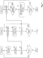
- Fig. 1 illustrates three processes, Process 1, Process 2, and Process 3, where Processes 1 and 2, and 3 and 2, respectively, may be implemented at different locations, and Processes 1 and 3 may be implemented in the same location.
- the process 1 comprises the steps of: sampling (S1) a voice signal, such as a phonation stream, of a subject over a predetermined period of time, thereby obtaining sample data of the voice signal, forming (S2) a data packet from the sample data, sending (S3) the data packet to one Calculating means and repeating these steps as long as process 1 does not finish (No in S4).
- a voice signal such as a phonation stream
- the process 3 includes the steps of receiving (S9) T0 at the scanner, checking (S10) whether a timer has expired, outputting a trigger signal, and setting (S11) the timer to TO when the timer has expired (Yes in S10 ), and repeating these steps as long as process 3 is not finished (No in S11).
- the timer may be set to a predetermined value of T0. If the received value of T0 is different from the predetermined value of T0 or the previously set value of T0, the timer after its expiration is set to the received value of T0. That is, the timer is always set to the current value of T0.
- the timer is preferably located on the side of the scanner which collects the scan data.
- the trigger signal is output to a flashlamp or a strobe to generate a flash signal, for example, for recording the vocal folds by a camera.
- the transition between the old and new value of T0 is performed, for example, using a known regulator ,
- the trigger signal output at the expiration of the timer can drive a stroboscope, which is arranged for example close to the glottis of the subject and together with a camera serves for taking a picture of the glottis.
- step S1 the voice signal is picked up, for example, with a microphone located near the glottis of the subject.
- the data packet formed in step S2 includes a certain number of samples of the voice signal detected by sampling the voice signal over the predetermined period of time. For example, the transition from step S1 to step S2 may be triggered when the determined number of samples is detected. That is, the formation of the data packet is triggered when the particular number of samples is detected.
- Fig. 2 shows a schematic block diagram of a device 100 for tracking the fundamental frequency of a voice signal according to an embodiment of the invention.
- the apparatus 100 includes a scanner 10 and a calculator 20.
- the processes 1 and 3 described above may be implemented in the scanner 10, which is attached to an endoscope, for example.
- the process 2 may be implemented in the computing device 20, which is provided separately.
- the sampling device 10 comprises a recording unit 11, a processing unit 12 and a timer 13.
- the recording unit 11 receives the voice signal picked up by the microphone.
- the microphone may be included by the receiving unit 11.
- the processing unit 12 receives the recorded voice signal from the recording unit 11, and performs sampling of the voice signal at a predetermined sampling frequency. In this case, samples are obtained which have a certain resolution in bits.
- the processing unit 12 merges the samples into data packets having a specific bit length. That is, a data packet contains a certain number of data values. Became a specific one Number of data values obtained by the scan, the processing unit 12 generates the data packet and sends it to the computing device 20.
- the functions of the processing unit 12 may be implemented by a DSP (Digital Signal Processor), a FPGA (Field Programmable Gate Array) or the like.
- the processor 12 may also include a processor and a memory that stores a program that, when executed by the processor, implements the above-described functions of the processor 12.
- the data packets may be sent to the computing device 20 via a serial interface 102.
- the connection between scanner 10 and computing device 20 may be wired or wireless.
- the functions of the computing device 20 may be implemented by a DSP (Digital Signal Processor), FPGA (Field Programmable Gate Array), or the like.
- the computing device 20 may also include a processor and memory that stores a program that, when executed by the processor, performs the above-described functions of the computing device 20.
- the time T0 sent by the calculation device 20 is supplied to the timer 13 via the processing unit 12, for example.
- the timer 13 is set to T0, and when the time T0 elapses, a trigger signal is outputted, for example, to drive a flashlamp or a stroboscope.
- FIG. 12 is a diagram illustrating detection and tracking of a fundamental frequency f0 of a voice signal according to an embodiment of the invention.
- y (t) represents a waveform of a voice signal of a subject.
- Fig. 3 shows the waveform as a sine wave with a frequency of 100Hz.
- the recording unit 11 can provide the signal curve y (t) for the processing unit 12.
- the sample rate used to sample the waveform is 44.1 kHz, which corresponds to a duration of approximately 22.7 ⁇ s.
- the resolution of a sample is 16 bits, and the packet length is 1023 bytes, which corresponds to a duration of approximately 23.22 ms. It is noted that the invention is not limited to these values.
- a data packet may, for example, contain ten oscillations of the voice signal.
- a trigger signal P (t) triggers the generation and transmission of the data packet.
- Fig. 3 shows data packets Packet 1, Packet 2, Packet 3 and Packet 4 whose generation and transmission are triggered by P (t).
- FIG Fig. 1 shown process 1 or by the scanning device 10 in Fig. 2 be performed.
- the fundamental frequency f0 of the signal curve y (t) is calculated.
- f0 is first calculated using the Packet 1 data package.
- Fig. 3 illustrates the delay between waveform sampling, packet generation, packet transmission, calculation of f0 and T0, and setting the timer to T0.
- the fundamental frequency f0 can be tracked over time.
- a real-time trigger signal for the flash lamp or the stroboscope which is synchronous with the voice signal, is generated again.
- a stroboscope is attached to an endoscope that is located near the glottis of the subject. Based on the trigger signal, the stroboscope generates a flash of light, and a camera attached to the endoscope records an image of the vocal folds.
- Fig. 3 illustrates the captured images as asynchronous image data packets Frame 1, Frame 2, Frame 3.
- the calculation of the fundamental frequency f0 described above can be performed in the Fig. 1 shown process 2 or by the calculation means 20 in Fig. 2 be performed.
- the generation of the trigger signal can be performed by the process 3 or the scanning device 10, in particular by setting the timer 13.
- the delay between the first sample for a data packet and activation with (newly) calculated fundamental frequency f0 is in Fig. 3 61.64 ms, which is negligible for taking pictures of the vocal folds.
- sample data obtained by sampling a voice signal is sent in data packets to a device where it is processed to acquire the fundamental frequency of the voice signal.
- the structure of the scanning device can be downsized.
Landscapes
- Health & Medical Sciences (AREA)
- Life Sciences & Earth Sciences (AREA)
- Engineering & Computer Science (AREA)
- Surgery (AREA)
- Physics & Mathematics (AREA)
- Public Health (AREA)
- General Health & Medical Sciences (AREA)
- Animal Behavior & Ethology (AREA)
- Molecular Biology (AREA)
- Medical Informatics (AREA)
- Heart & Thoracic Surgery (AREA)
- Biomedical Technology (AREA)
- Veterinary Medicine (AREA)
- Pathology (AREA)
- Biophysics (AREA)
- Acoustics & Sound (AREA)
- Signal Processing (AREA)
- Optics & Photonics (AREA)
- Radiology & Medical Imaging (AREA)
- Nuclear Medicine, Radiotherapy & Molecular Imaging (AREA)
- Physiology (AREA)
- Pulmonology (AREA)
- Audiology, Speech & Language Pathology (AREA)
- Otolaryngology (AREA)
- Human Computer Interaction (AREA)
- Computational Linguistics (AREA)
- Epidemiology (AREA)
- Multimedia (AREA)
- Artificial Intelligence (AREA)
- Computer Vision & Pattern Recognition (AREA)
- Psychiatry (AREA)
- Endoscopes (AREA)
Description
- Vorliegende Erfindung bezieht sich auf eine Nachführung eines Stimmsignals in Echtzeit.
- Eine Grundfrequenzanalyse des Stimmsignals eines Probanden ist beispielsweise auf dem Gebiet der Stroboskopie erforderlich. Mittels der Stroboskopie kann die Beweglichkeit der Stimmlippen beurteilt werden. Die Triggerung einer Bildaufnahme der Stimmlippen erfolgt beispielsweise durch die Phonation des Probanden über ein Körper- oder Luftleitungsmikrofon.
- Zum Initiieren der Phonation werden die Stimmlippen in Phonationsstellung gebracht, das heißt, sie liegen locker aneinander an und verschließen so die Glottis. Durch den Luftstrom werden die Stimmlippen in Schwingung versetzt, so dass die Luft mit jeder Öffnung und Schließung stoßweise in den Artikulationsraum entlassen wird. Es entstehen komplizierte periodische, aus Teiltönen bestehende Schwingungen. Die Frequenz, e.g. 70-1000 Hz, hängt dabei von der Länge der Stimmlippen ab.
- Auf dem Gebiet der Stroboskopie wird ein Stroboskop beruhend auf dieser (Grund-)Frequenz angesteuert. Das an einem Endoskop angebrachte Stroboskop dient zur Aufnahme von Bildern der Stimmlippen zu geeigneten Zeitpunkten, die mittels der Grundfrequenz des Stimmsignals bestimmt werden.
- Eine Aufgabe der Erfindung besteht in einer Vereinfachung eines Aufbaus zur Nachführung der Grundfrequenz eines Stimmsignals beispielsweise bei der Spektroskopie.
- Diese Aufgabe wird durch das Verfahren und die Vorrichtung gemäß den beigefügten Patentansprüchen gelöst.
- Erfindungsgemäß tastet eine Abtasteinrichtung ein Stimmsignal eines Probanden über einen vorbestimmten Zeitabschnitt ab, wodurch Abtastdaten des Stimmsignals erhalten werden, bildet ein Datenpaket aus den Abtastdaten, und sendet das Datenpaket zu einer Berechnungseinrichtung. Die Berechnungseinrichtung empfängt das Datenpaket und berechnet eine Grundfrequenz des Stimmsignals anhand der in dem Datenpaket enthaltenen Abtastdaten. Die Abtasteinrichtung setzt einen Zeitgeber beruhend auf der von der Berechnungseinrichtung berechneten Grundfrequenz und gibt ein Triggersignals bei Ablauf des Zeitgebers aus. Ein Vorteil der Erfindung liegt darin, dass Aufnahme des Stimmsignals und Analyse des Stimmsignals an verschiedenen Orten durchgeführt werden können, wodurch der Aufbau einer Aufnahmeeinrichtung verkleinert werden kann. Zudem ist es möglich, die Grundfrequenz des Stimmsignals asynchron zur Ansteuerung eines Stroboskops zu ermitteln, wodurch ein aufwendiger Aufbau zur Ermittlung der Grundfrequenz in Echtzeit vermieden werden kann.
- Dokument
WO 2009/008596 A1 (UMEDICAL CO LTD) offenbart ein Endoskop mit Stroboskop mit Mikrophon. Das Audiosignal wird aufgenommen und die Grundfrequenz ermittelt, womit ein Triggersignal erstellt wird. - Dokument
JP 2002 291699 - Die Erfindung wird nachstehend anhand von Ausführungsbeispielen unter Bezugnahme auf die beiliegenden Zeichnungen näher beschreiben. Es zeigen:
-
Fig. 1 Ablaufdiagramme für einen Prozess 1, einen Prozess 2 und einen Prozess 3 zur Nachführung der Grundfrequenz eines Stimmsignals gemäß einem Ausführungsbeispiel der Erfindung. -
Fig. 2 ein schematisches Blockschaltbild einer Vorrichtung zur Nachführung der Grundfrequenz eines Stimmsignals gemäß einem Ausführungsbeispiel der Erfindung. -
Fig. 3 eine schematische Darstellung einer Nachführung der Grundfrequenz eines Stimmsignals gemäß einem Ausführungsbeispiel der Erfindung. -
Fig. 1 veranschaulicht drei Prozesse, Prozess 1, Prozess 2 und Prozess 3, wobei die Prozesse 1 und 2 bzw. 3 und 2 jeweils an verschiedenen Orten implementiert sein können, und die Prozesse 1 und 3 an demselben Ort implementiert sein können. - Der Prozess 1 umfasst die Schritte: Abtasten (S1) eines Stimmsignals, beispielsweise eines Phonationsstroms, eines Probanden über einen vorbestimmten Zeitabschnitt, wodurch Abtastdaten des Stimmsignals erhalten werden, Bilden (S2) eines Datenpakets aus den Abtastdaten, Senden (S3) des Datenpakets zu einer Berechnungseinrichtung und Wiederholen dieser Schritte, solange Prozess 1 nicht beendet wird (Nein in S4).
- Der Prozess 2 umfasst die Schritte: Empfangen (S5) des Datenpakets von einer Abtasteinrichtung, Berechnen (S6) einer Grundfrequenz f0 des Stimmsignals anhand der in dem Datenpaket enthaltenen Abtastdaten an der Berechnungseinrichtung und Berechnen von T0=1/f0, Senden (S7) von T0 zu der Abtasteinrichtung, und Wiederholen dieser Schritte, solange Prozess 2 nicht beendet wird (Nein in S8).
- Der Prozess 3 umfasst die Schritte: Empfangen (S9) von T0 an der Abtasteinrichtung, Überprüfen (S10), ob ein Zeitgeber abgelaufen ist, Ausgeben eines Triggersignals und Setzen (S11) des Zeitgebers auf TO, wenn der Zeitgeber abgelaufen ist (Ja in S10), und Wiederholen dieser Schritte, solange Prozess 3 nicht beendet wird (Nein in S11).
- Zu Beginn von Prozess 3, wenn noch kein T0 von Prozess 2 empfangen wurde, kann der Zeitgeber auf einen vorbestimmten Wert von T0 eingestellt werden. Ist der empfangene Wert von T0 von dem vorbestimmten Wert von T0 oder von dem zuvor eingestellten Wert von T0 verschieden, wird der Zeitgeber nach seinem Ablauf auf den empfangenen Wert von T0 eingestellt. Das heißt, der Zeitgeber wird immer auf den aktuellen Wert von T0 gesetzt.
- Der Zeitgeber befindet sich vorzugsweise auf der Seite der Abtastvorrichtung, die die Abtastdaten sammelt. Bei Ablauf des Zeitgebers wird das Triggersignal zu einer Blitzlampe bzw. einem Stroboskop ausgegeben, um ein Blitzsignal beispielsweise für die Aufnahme der Stimmlippen durch eine Kamera zu erzeugen.
- Um Sprünge zwischen einem zuvor in dem Zeitgeber einstellten Wert von T0 und einem neu in dem Zeitgeber einzustellenden Wert von T0 zu vermeiden, wird gemäß einem Ausführungsbeispiel der Erfindung der Übergang zwischen dem alten und neuen Wert von T0 gleitend, beispielsweise unter Verwendung eines bekannten Reglers durchgeführt.
- Das bei Ablauf des Zeitgebers ausgegebene Triggersignal kann ein Stroboskop ansteuern, das beispielsweise nahe der Glottis des Probanden angeordnet ist und zusammen mit einer Kamera zur Aufnahme eines Bildes der Glottis dient.
- In Schritt S1 wird das Stimmsignal beispielsweise mit einem Mikrophon aufgenommen, das nahe der Glottis des Probanden angeordnet ist.
- Das in Schritt S2 gebildete Datenpaket enthält eine bestimmte Anzahl an Abtastwerten des Stimmsignals, die durch das Abtasten des Stimmsignals über den vorbestimmten Zeitabschnitt erfasst werden. Beispielsweise kann der Übergang von Schritt S1 zu Schritt S2 getriggert werden, wenn die bestimmte Anzahl der Abtastwerte erfasst ist. D.h., die Bildung des Datenpakets wird getriggert, wenn die bestimmte Anzahl der Abtastwerte erfasst ist.
-
Fig. 2 zeigt ein schematisches Blockschaltbild einer Vorrichtung 100 zur Nachführung der Grundfrequenz eines Stimmsignals gemäß einem Ausführungsbeispiel der Erfindung. - Die Vorrichtung 100 umfasst eine Abtasteinrichtung 10 und eine Berechnungseinrichtung 20. Die vorstehend beschriebenen Prozesse 1 und 3 können in der Abtasteinrichtung 10 implementiert sein, die beispielsweise an einem Endoskop angebracht ist. Der Prozess 2 kann in der Berechnungseinrichtung 20 implementiert sein, die separat vorgesehen ist.
- Die Abtasteinrichtung 10 umfasst eine Aufnahmeeinheit 11, eine Verarbeitungseinheit 12 und einen Zeitgeber 13. Die Aufnahmeeinheit 11 erhält das von dem Mikrophon aufgenommene Stimmsignal. Das Mikrophon kann durch die Aufnahmeeinheit 11 umfasst sein.
- Die Verarbeitungseinheit 12 erhält das aufgenommene Stimmsignal von der Aufnahmeeinheit 11 und führt eine Abtastung des Stimmsignals mit einer bestimmten Abtastfrequenz durch. Dabei werden Abtastwerte erhalten, die eine bestimme Auflösung in Bits haben. Die Verarbeitungseinheit 12 fügt die Abtastwerte zu Datenpaketen mit einer bestimmten Bitlänge zusammen. D.h., ein Datenpaket enthält eine bestimmte Anzahl an Datenwerten. Wurde eine bestimmte Anzahl an Datenwerten durch die Abtastung erhalten, erzeugt die Verarbeitungseinheit 12 das Datenpaket und sendet es zu der Berechnungseinrichtung 20. Die Funktionen der Verarbeitungseinheit 12 können durch einen DSP (Digital Signal Processor), ein FPGA (Field Programmable Gate Array) oder dergleichen implementiert sein. Die Verarbeitungseinrichtung 12 kann auch einen Prozessor und einen Speicher umfassen, der ein Programm speichert, das bei Ausführung durch den Prozessor die vorstehend beschriebenen Funktionen der Verarbeitungseinrichtung 12 verwirklicht.
- Die Datenpakete können über eine serielle Schnittstelle 102 zu der Berechnungseinrichtung 20 gesendet werden. Die Verbindung zwischen Abtasteinrichtung 10 und Berechnungseinrichtung 20 kann drahtgebunden oder drahtlos sein.
- Die Berechnungseinrichtung 20 empfängt das Datenpaket von der Abtasteinrichtung 10 und berechnet anhand der darin enthaltenen Abtastwerte die Grundfrequenz f0 des Stimmsignals. Das heißt, die Berechnungseinrichtung 20 führt eine Frequenzanalyse des Stimmsignals anhand der in dem Datenpaket enthaltenen Abtastwerte durch. Die Berechnungseinrichtung 20 berechnet auch eine Zeit T0=1/f0. Die Berechnungseinrichtung 20 sendet T0 beispielsweise über die serielle Schnittstelle 102 zu der Abtasteinrichtung 10.
- Die Funktionen der Berechnungseinrichtung 20 können durch einen DSP (Digital Signal Processor), ein FPGA (Field Programmable Gate Array) oder dergleichen implementiert sein. Die Berechnungseinrichtung 20 kann auch einen Prozessor und einen Speicher umfassen, der ein Programm speichert, das bei Ausführung durch den Prozessor die vorstehend beschriebenen Funktionen der Berechnungseinrichtung 20 verwirklicht.
- Die von der Berechnungseinrichtung 20 gesendete Zeit T0 wird dem Zeitgeber 13 beispielsweise über die Verarbeitungseinheit 12 zugeführt. Der Zeitgeber 13 wird auf T0 gesetzt, und bei Ablauf der Zeit T0 wird ein Triggersignal beispielsweise zur Ansteuerung einer Blitzlampe bzw. eines Stroboskops ausgegeben.
-
Fig. 3 zeigt eine Darstellung, die Erfassung und Nachführung einer Grundfrequenz f0 eines Stimmsignals gemäß einem Ausführungsbeispiel der Erfindung veranschaulicht. - y(t) stellt einen Signalverlauf eines Stimmsignals eines Probanden dar.
Fig. 3 zeigt den Signalverlauf als Sinuswelle mit einer Frequenz von 100Hz. Beispielsweise kann die Aufnahmeeinheit 11 den Signalverlauf y(t) für die Verarbeitungseinheit 12 bereitstellen. - Die Abtastrate, mit der der Signalverlauf abgetastet wird, beträgt 44,1kHz, was einer Zeitdauer von ca. 22,7µs entspricht. Die Auflösung eines Abtastwerts beträgt 16Bit, und die Paketlänge umfasst 1023 Byte, was einer Zeitdauer von ca. 23,22ms entspricht. Es wird angemerkt, dass die Erfindung nicht auf diese Werte beschränkt ist. Ein Datenpaket kann beispielsweise zehn Schwingungen des Stimmsignals enthalten.
- Wurden 1024 Byte an Abtastwerten erhalten, triggert ein Triggersignal P(t) das Erzeugen bzw. Fertigstellen und Senden des Datenpakets.
Fig. 3 zeigt Datenpakete Packet 1, Packet 2, Packet 3 und Packet 4, deren Erzeugung und Senden durch P(t) getriggert werden. - Das vorstehend beschriebene Abtasten des Signalverlaufs y(t) und die Erzeugung und das Senden der Datenpakete können im in
Fig. 1 gezeigten Prozess 1 bzw. durch die Abtasteinrichtung 10 inFig. 2 durchgeführt werden. - Anhand der in den Datenpaketen enthaltenen Abtastwerte wird die Grundfrequenz f0 des Signalverlaufs y(t) berechnet. f0 wird erstmals anhand des Datenpakets Packet 1 berechnet.
Fig. 3 veranschaulicht die Verzögerung zwischen Signalverlaufabtastung, Paketerzeugung, Senden des Pakets, Berechnung von f0 und T0 und Setzen des Zeitgebers auf T0. - Mit der erstmaligen Berechnung von f0 wird der Zeitgeber auf T0=1/f0 gesetzt. Hat sich nach Verarbeitung des Datenpakets Packet 2 f0 verändert, wird der Zeitgeber nach Ablauf der zuvor gesetzten Zeit auf die neu berechnete Zeit eingestellt, oder der alte Wert von T0 und der neue Wert von T0 können gemittelt werden. Es ist auch möglich, eine konstante Phase oder eine mit der Zeit ansteigende Phase zu T0 zu addieren, um einen gleitenden Übergang zwischen altem und neuem Wert von T0 zu ermöglichen.
- Mit der vorstehend beschriebenen Konfiguration kann die Grundfrequenz f0 über die Zeit nachgeführt werden. Insbesondere wird beruhend auf dem zum Stimmsignal asynchronen Vorgang des Verarbeitens der Datenpakete wieder ein zum Stimmsignal synchrones Echtzeit-Triggersignal für die Blitzlampe bzw. das Stroboskop erzeugt.
- Beispielsweise ist ein Stroboskop an einem Endoskop angebracht, das sich in der Nähe der Glottis des Probanden befindet. Anhand des Triggersignals erzeugt das Stroboskop einen Lichtblitz, und eine am Endoskop angebrachte Kamera nimmt ein Bild der Stimmlippen auf.
Fig. 3 veranschaulicht die aufgenommenen Bilder als asynchrone Bilddatenpakete Frame 1, Frame 2, Frame 3. - Die vorstehend beschriebene Berechnung der Grundfrequenz f0 kann im in
Fig. 1 gezeigten Prozess 2 bzw. durch die Berechnungseinrichtung 20 inFig. 2 durchgeführt werden. Die Erzeugung des Triggersignals kann durch den Prozess 3 bzw. die Abtasteinrichtung 10, insbesondere durch Setzen des Zeitgebers 13 durchgeführt werden. - Die Verzögerung zwischen erster Abtastung für ein Datenpaket und Ansteuerung mit (neu) berechneter Grundfrequenz f0 beträgt im in
Fig. 3 gezeigten Beispiel ca. 61,64ms, was aber für die Aufnahme geeigneter Bilder der Stimmlippen vernachlässigbar ist. - Erfindungsgemäß werden durch Abtastung eines Stimmsignals erhaltene Abtastdaten in Datenpaketen zu einer Einrichtung gesendet, wo sie zum Erfassen der Grundfrequenz des Stimmsignals verarbeitet werden. Dadurch kann der Aufbau an der Abtasteinrichtung verkleinert werden. Zudem ist es möglich, die Grundfrequenz des Stimmsignals asynchron zur Ansteuerung eines Stroboskops zu ermitteln, wodurch ein aufwendiger Aufbau zur Ermittlung der Grundfrequenz in Echtzeit vermieden werden kann.
Claims (6)
- Verfahren für eine Vorrichtung (100) zur Nachführung einer Grundfrequenz eines Stimmsignals, wobei die Vorrichtung (100) eine an einem Endoskop angebrachte Abtasteinrichtung (10), eine Berechnungseinrichtung (20) und eine serielle Schnittstelle (102) enthält, die die Berechnungseinrichtung (20) und die Abtasteinrichtung (10) verbindet, wobei die Abtasteinrichtung (10) ein Mikrophon (11) umfasst, das nahe der Glottis eines Probanden angeordnet ist und ein Stimmsignal des Probanden aufnimmt, wobei das Verfahren die Schritte umfasst:(a) Abtasten (S1) des Stimmsignals des Probanden über einen vorbestimmten Zeitabschnitt an der Abtasteinrichtung, wodurch Abtastdaten des Stimmsignals erhalten werden, wobei der vorbestimmte Zeitabschnitt eine bestimmte Anzahl an Schwingungen des Stimmsignals umfasst, und Triggern von Schritt (b), wenn eine bestimmte Anzahl an Abtastwerten durch das Abtasten des Stimmsignals über den vorbestimmten Zeitabschnitt erfasst ist,(b) Bilden (S2) eines Datenpakets aus den Abtastdaten an der Abtasteinrichtung, wobei das Datenpaket die bestimmte Anzahl an Abtastwerten des Stimmsignals enthält,(c) Senden (S3) des Datenpakets von der Abtasteinrichtung über die serielle Schnittstelle (102) zu der Berechnungseinrichtung,(d) Berechnen (S6) einer Grundfrequenz des Stimmsignals anhand der in dem Datenpaket enthaltenen Abtastdaten an der Berechnungseinrichtung und Senden der berechneten Grundfrequenz über die serielle Schnittstelle zu der Abtasteinrichtung,(e) Setzen eines Zeitgebers beruhend auf der von der Berechnungseinrichtung gesendeten Grundfrequenz, und(f) Ausgeben eines Triggersignals bei Ablauf des Zeitgebers,wobei die Schritte (a) bis (d) eine bestimmte Anzahl oft wiederholt werden, Schritt (e) nach Ablauf des Zeitgebers durchgeführt wird, und Schritt (d) asynchron zu den Schritten (a) bis (c), (e) und (f) durchgeführt wird, und
wobei die Schritte (a) bis (c), (e) und (f) durch einen Prozessor der Abtasteinrichtung (10) durchgeführt werden, der ein in einem Speicher der Abtasteinrichtung (10) gespeichertes Programm ausführt, und
wobei Schritt (d) durch einen Prozessor der Berechnungseinrichtung (20) durchgeführt wird, der ein in einem Speicher der Berechnungseinrichtung (20) gespeichertes Programm ausführt. - Verfahren nach Anspruch 1, ferner mit dem Schritt:
Ausgeben des Triggersignals zu einem an dem Endoskop angebrachten Stroboskop, das nahe der Glottis des Probanden angeordnet ist. - Verfahren nach Anspruch 1, wobei das Setzen des Zeitgebers beruhend auf der von der Berechnungseinrichtung gesendeten Grundfrequenz an der Abtasteinrichtung durchgeführt wird, und das Ausgeben eines Triggersignals bei Ablauf des Zeitgebers durch die Abtasteinrichtung durchgeführt wird.
- Verfahren nach einem der Ansprüche 1 bis 3, wobei das Stimmsignal ein Phonationsstrom ist.
- Vorrichtung (100) zur Nachführung einer Grundfrequenz eines Stimmsignals, mit:einer Abtasteinrichtung (10), die an einem Endoskop angebracht ist, wobei die Abtasteinrichtung (10) ein Mikrophon (11) umfasst, das nahe der Glottis eines Probanden angeordnet werden kann und zur Aufnahme eines Stimmsignals des Probanden eingerichtet ist,einer Berechnungseinrichtung (20), undeiner seriellen Schnittstelle (102), die die Berechnungseinrichtung (20) und die Abtasteinrichtung (10) verbindet,wobei die Abtasteinrichtung zum (a) Abtasten des Stimmsignals des Probanden über einen vorbestimmten Zeitabschnitt, wodurch Abtastdaten des Stimmsignals erhalten werden, wobei der vorbestimmte Zeitabschnitt eine bestimmte Anzahl an Schwingungen des Stimmsignals umfasst, wenn eine bestimmte Anzahl an Abtastwerten durch das Abtasten des Stimmsignals über den vorbestimmten Zeitabschnitt erfasst ist, Triggern des Bildens eines Datenpakets aus den Abtastdaten und Senden des Datenpakets über die serielle Schnittstelle (102) zu der Berechnungseinrichtung (20) eingerichtet ist, wobei das Datenpaket die bestimmte Anzahl an Abtastwerten des Stimmsignals enthält,wobei die Berechnungseinrichtung (20) zum Empfangen des Datenpakets über die serielle Schnittstelle (102), Berechnen einer Grundfrequenz des Stimmsignals anhand der in dem Datenpaket enthaltenen Abtastdaten und Senden der berechneten Grundfrequenz über die serielle Schnittstelle (102) zu der Abtasteinrichtung (10) eingerichtet ist,wobei die Abtasteinrichtung (10) zum (b) Setzen eines Zeitgebers beruhend auf der von der Berechnungseinrichtung (20) gesendeten Grundfrequenz und Ausgeben eines Triggersignals bei Ablauf des Zeitgebers eingerichtet ist,und wobei die Berechnungseinrichtung zum Berechnen der Grundfrequenz und Senden der berechneten Grundfrequenz über die serielle Schnittstelle (102) zu der Abtasteinrichtung asynchron zu den Verarbeitungsvorgängen (a) und (b) der Abtasteinrichtung eingerichtet ist, undwobei die Abtasteinrichtung (10) einen Prozessor und einen Speicher umfasst, wobei der Prozessor der Abtasteinrichtung die Schritte (a) bis (c), (e) und (f) durch Ausführen eines in dem Speicher der Abtasteinrichtung gespeicherten Programms durchführt, undwobei die Berechnungseinrichtung (20) einen Prozessor und einen Speicher umfasst, wobei der Prozessor der Berechnungseinrichtung Schritt (d) durch Ausführen eines in dem Speicher der Berechnungseinrichtung gespeicherten Programms durchführt.
- Vorrichtung nach Anspruch 5, wobei die Abtasteinrichtung (10) zur Ausgabe des Triggersignals zu einem Stroboskop eingerichtet ist, das an dem Endoskop angebracht ist.
Applications Claiming Priority (2)
| Application Number | Priority Date | Filing Date | Title |
|---|---|---|---|
| DE102014201286.4A DE102014201286B4 (de) | 2014-01-24 | 2014-01-24 | Verfahren und vorrichtung zur nachführung der grundfrequenz eines stimmsignals in echtzeit |
| PCT/EP2015/051245 WO2015110525A1 (de) | 2014-01-24 | 2015-01-22 | Nachführung der grundfrequenz eines stimmsignals in echtzeit |
Publications (2)
| Publication Number | Publication Date |
|---|---|
| EP3096676A1 EP3096676A1 (de) | 2016-11-30 |
| EP3096676B1 true EP3096676B1 (de) | 2019-04-24 |
Family
ID=52434781
Family Applications (1)
| Application Number | Title | Priority Date | Filing Date |
|---|---|---|---|
| EP15701748.4A Active EP3096676B1 (de) | 2014-01-24 | 2015-01-22 | Nachführung der grundfrequenz eines stimmsignals in echtzeit |
Country Status (6)
| Country | Link |
|---|---|
| US (1) | US10441152B2 (de) |
| EP (1) | EP3096676B1 (de) |
| JP (1) | JP6412145B2 (de) |
| CN (1) | CN106413522B (de) |
| DE (1) | DE102014201286B4 (de) |
| WO (1) | WO2015110525A1 (de) |
Families Citing this family (4)
| Publication number | Priority date | Publication date | Assignee | Title |
|---|---|---|---|---|
| US10835116B2 (en) * | 2017-11-16 | 2020-11-17 | Karl Storz Imaging, Inc. | Vocal cord stroboscopy |
| CN113677255B (zh) | 2019-04-03 | 2025-01-24 | 奥林巴斯株式会社 | 无线内窥镜、无线内窥镜装置以及照明控制方法 |
| WO2022216525A1 (en) | 2021-04-07 | 2022-10-13 | Pentax Of America, Inc. | Laryngeal stroboscope utilizing solid state light sources |
| CN114224498B (zh) * | 2021-12-13 | 2023-04-18 | 复旦大学 | 一种用于复杂气道多模态气管插管机器人的主从控制系统 |
Citations (1)
| Publication number | Priority date | Publication date | Assignee | Title |
|---|---|---|---|---|
| JP2002291699A (ja) * | 2001-03-30 | 2002-10-08 | Asahi Optical Co Ltd | 声帯観察用の内視鏡システム |
Family Cites Families (87)
| Publication number | Priority date | Publication date | Assignee | Title |
|---|---|---|---|---|
| US3549806A (en) | 1967-05-05 | 1970-12-22 | Gen Electric | Fundamental pitch frequency signal extraction system for complex signals |
| US3605725A (en) | 1968-08-07 | 1971-09-20 | Medi Tech Inc | Controlled motion devices |
| DE6905185U (de) | 1969-02-11 | 1972-04-06 | Bowden Controls Ltd | Bowdenzug. |
| US3774394A (en) | 1971-08-09 | 1973-11-27 | Gen Electric | Gas turbine engine fuel drain system and cooperating valve and pump means |
| JPS6121041Y2 (de) | 1977-08-04 | 1986-06-24 | ||
| JPS5939128B2 (ja) | 1979-10-31 | 1984-09-21 | オリンパス光学工業株式会社 | 内視鏡 |
| JPS57110228A (en) | 1980-12-26 | 1982-07-09 | Olympus Optical Co | Air and water sending switch apparatus of endoscope |
| US4415767A (en) * | 1981-10-19 | 1983-11-15 | Votan | Method and apparatus for speech recognition and reproduction |
| JPS60148536A (ja) | 1984-01-17 | 1985-08-05 | オリンパス光学工業株式会社 | 内視鏡 |
| JPS61118713A (ja) | 1984-11-14 | 1986-06-06 | Olympus Optical Co Ltd | 内視鏡 |
| US4670009A (en) | 1985-04-16 | 1987-06-02 | American Hospital Supply Corp. | Backform inserts for catheter |
| JPS62227312A (ja) | 1986-03-27 | 1987-10-06 | 旭光学工業株式会社 | 内視鏡の湾曲操作ワイヤの取付構造 |
| US5245133A (en) | 1991-10-15 | 1993-09-14 | Thomas & Betts Corporation | Moisture-resistant cable splice and sealing structure thereof |
| JP3219521B2 (ja) | 1993-03-01 | 2001-10-15 | オリンパス光学工業株式会社 | 内視鏡 |
| US5569157A (en) | 1993-05-07 | 1996-10-29 | Olympus Optical Co., Ltd. | Endoscope |
| US5588950A (en) | 1994-07-11 | 1996-12-31 | Asahi Kogaku Kogyo Kabushiki Kaisha | Portable endoscope system |
| US5630419A (en) | 1994-12-20 | 1997-05-20 | Tetrad Corporation | Sealing connector for multiconductor cables |
| DE19627016C1 (de) | 1996-07-04 | 1998-02-12 | Etm Endotech Gmbh Medizintechn | Flexibles Endoskop |
| US5845241A (en) * | 1996-09-04 | 1998-12-01 | Hughes Electronics Corporation | High-accuracy, low-distortion time-frequency analysis of signals using rotated-window spectrograms |
| JPH10225439A (ja) | 1997-02-17 | 1998-08-25 | Olympus Optical Co Ltd | 内視鏡用撮像装置 |
| DE19731965A1 (de) | 1997-07-24 | 1999-01-28 | Etm Endotech Gmbh Medizintechn | Luft/Wasser- und Absaugventile an Endoskopen |
| DE19840986A1 (de) | 1998-09-08 | 2000-03-09 | Etm Endoskopische Technik Gmbh | Schnellverschluss für ein Endoskop |
| DE19843337A1 (de) | 1998-09-22 | 2000-03-23 | Sram De Gmbh | Justiereinrichtung für Betätigungszüge zum Steuern von Fahrradgetrieben |
| US6734893B1 (en) | 1998-12-04 | 2004-05-11 | Olympus Winter & Ibe Gmbh | Endoscopy illumination system for stroboscopy |
| JP3179426B2 (ja) | 1998-12-21 | 2001-06-25 | オリンパス光学工業株式会社 | 内視鏡装置 |
| US6547722B1 (en) | 1999-07-13 | 2003-04-15 | Olympus Optical Co., Ltd. | Endoscope having resistance to high-temperature and high-pressure steam |
| JP2001061772A (ja) | 1999-08-30 | 2001-03-13 | Fuji Photo Optical Co Ltd | 内視鏡の流体制御装置 |
| JP3488170B2 (ja) | 2000-03-21 | 2004-01-19 | オリンパス株式会社 | 内視鏡 |
| JP3821206B2 (ja) | 2000-09-29 | 2006-09-13 | フジノン株式会社 | 内視鏡のコネクタ用防水キャップ |
| JP2002160691A (ja) | 2000-11-28 | 2002-06-04 | Nissin Kogyo Co Ltd | バーハンドル車両用ブレーキ装置 |
| JP4589521B2 (ja) * | 2000-12-07 | 2010-12-01 | Hoya株式会社 | 電子内視鏡光源装置 |
| JP2002238831A (ja) | 2001-02-16 | 2002-08-27 | Fuji Photo Optical Co Ltd | 内視鏡 |
| DE10121450A1 (de) | 2001-04-27 | 2002-11-21 | Storz Endoskop Gmbh Schaffhaus | Optisches Instrument, insbesondere Endoskop, mit Wechselkopf |
| US20060199999A1 (en) | 2001-06-29 | 2006-09-07 | Intuitive Surgical Inc. | Cardiac tissue ablation instrument with flexible wrist |
| US6793622B2 (en) | 2001-09-05 | 2004-09-21 | Olympus Optical Co., Ltd. | Electric bending endoscope |
| JP2003190085A (ja) | 2001-12-25 | 2003-07-08 | Olympus Optical Co Ltd | 電気的コネクタ |
| JP2004049891A (ja) | 2002-05-29 | 2004-02-19 | Olympus Corp | 内視鏡装置 |
| JP2007111541A (ja) | 2002-05-29 | 2007-05-10 | Olympus Corp | 内視鏡装置と内視鏡用接続装置 |
| US7179223B2 (en) | 2002-08-06 | 2007-02-20 | Olympus Optical Co., Ltd. | Endoscope apparatus having an internal channel |
| JP4246986B2 (ja) * | 2002-11-18 | 2009-04-02 | 株式会社町田製作所 | 振動物体観察システム及び声帯観察用処理装置 |
| DE10320228A1 (de) | 2003-05-05 | 2004-11-25 | Stm Medizintechnik Starnberg Gmbh | Endoskopschaft |
| US7842028B2 (en) | 2005-04-14 | 2010-11-30 | Cambridge Endoscopic Devices, Inc. | Surgical instrument guide device |
| JP4461100B2 (ja) | 2004-02-16 | 2010-05-12 | オリンパス株式会社 | 内視鏡システム |
| AU2005228956B2 (en) | 2004-03-23 | 2011-08-18 | Boston Scientific Limited | In-vivo visualization system |
| JP2005304586A (ja) | 2004-04-19 | 2005-11-04 | Pentax Corp | 側方視型内視鏡の先端部 |
| US7811277B2 (en) | 2004-09-30 | 2010-10-12 | Boston Scientific Scimed, Inc. | Steerable device and system |
| JP4661190B2 (ja) | 2004-11-30 | 2011-03-30 | 富士フイルム株式会社 | 洗浄アダプタ |
| CN2762381Y (zh) | 2004-12-17 | 2006-03-01 | 亮泰企业股份有限公司 | 交流电源插头及插座的防水结构 |
| US20060252993A1 (en) | 2005-03-23 | 2006-11-09 | Freed David I | Medical devices and systems |
| EP1886617A4 (de) | 2005-05-26 | 2010-09-29 | Ars Co Ltd | Endoskopvorrichtung |
| WO2007002526A1 (en) | 2005-06-24 | 2007-01-04 | Everest Vit, Inc. | Insertion tube storage carousel |
| JP4987257B2 (ja) | 2005-06-29 | 2012-07-25 | オリンパス株式会社 | 内視鏡 |
| JP3882088B1 (ja) * | 2005-08-17 | 2007-02-14 | 国立大学法人 岡山大学 | 振動体観察装置、声帯観察装置及び声帯観察プログラム |
| DE102005041454A1 (de) | 2005-08-31 | 2007-03-01 | Karl Storz Gmbh & Co. Kg | Endoskop |
| AU2007201204B2 (en) | 2006-03-23 | 2012-07-12 | Ethicon Endo-Surgery, Inc. | Articulating endoscopic accessory channel |
| US20070225562A1 (en) | 2006-03-23 | 2007-09-27 | Ethicon Endo-Surgery, Inc. | Articulating endoscopic accessory channel |
| JP4812515B2 (ja) | 2006-05-26 | 2011-11-09 | 富士フイルム株式会社 | 洗浄アダプタ |
| EP1859727A1 (de) * | 2006-05-26 | 2007-11-28 | Stichting voor de Technische Wetenschappen | Optische Triggervorrichtung für Stroboskopie und stroboskopische Vorrichtung |
| US7615067B2 (en) | 2006-06-05 | 2009-11-10 | Cambridge Endoscopic Devices, Inc. | Surgical instrument |
| JP2008119057A (ja) | 2006-11-08 | 2008-05-29 | Matsushita Electric Works Ltd | カプセル型撮像装置 |
| KR200444134Y1 (ko) | 2007-07-09 | 2009-04-10 | 유메디칼 주식회사 | 음성신호를 이용한 후두 스트로보스코프 |
| US9005238B2 (en) | 2007-08-23 | 2015-04-14 | Covidien Lp | Endoscopic surgical devices |
| TWI348541B (en) * | 2008-01-11 | 2011-09-11 | Ind Tech Res Inst | Method and apparatus for identifying dynamic characteristics of a vibratory object |
| JP2009201762A (ja) | 2008-02-28 | 2009-09-10 | Hoya Corp | 内視鏡および撮影モジュール |
| EP2119390B1 (de) | 2008-05-16 | 2011-07-20 | FUJIFILM Corporation | Anschlussstück für Endoskop |
| CN102307510B (zh) | 2008-12-10 | 2014-10-08 | 阿姆布股份有限公司 | 具有照相机壳体的内窥镜及制造照相机壳体的方法 |
| US8700129B2 (en) | 2008-12-31 | 2014-04-15 | St. Jude Medical, Atrial Fibrillation Division, Inc. | Devices and methods for catheter localization |
| US8512371B2 (en) | 2009-10-06 | 2013-08-20 | Covidien Lp | Jaw, blade and gap manufacturing for surgical instruments with small jaws |
| DE102009060500B4 (de) | 2009-12-22 | 2015-12-17 | Xion Gmbh | Verfahren zur stroboskopischen Untersuchung sich wiederholender Vorgänge und Anordnung zum Betreiben dieses Verfahrens |
| WO2011108157A1 (ja) | 2010-03-05 | 2011-09-09 | オリンパスメディカルシステムズ株式会社 | 内視鏡 |
| CN102791182A (zh) | 2010-03-16 | 2012-11-21 | 奥林巴斯医疗株式会社 | 连接器座、连接器连接系统、光源装置和内窥镜 |
| TW201201641A (en) | 2010-06-18 | 2012-01-01 | Sun Wei Ren | Micro sensor |
| DE102010034623A1 (de) | 2010-08-17 | 2012-02-23 | Olympus Winter & Ibe Gmbh | Endoskop mit Videokamera im Schaftkörper |
| DE102010039731A1 (de) | 2010-08-25 | 2012-03-01 | Olympus Winter & Ibe Gmbh | Elektrisches Verbindungselement und Endoskopiesystem |
| JP5552014B2 (ja) | 2010-09-29 | 2014-07-16 | 富士フイルム株式会社 | 内視鏡の吸引ボタン |
| CN102665525B (zh) | 2010-12-24 | 2013-09-25 | 奥林巴斯株式会社 | 内窥镜装置 |
| EP2659656B1 (de) * | 2010-12-29 | 2018-07-18 | Skype | Dynamische anpassung von datencodierung abhänig der cpu-last |
| JP5851118B2 (ja) | 2011-05-25 | 2016-02-03 | オリンパス株式会社 | 内視鏡装置 |
| EP2740397B1 (de) | 2011-08-03 | 2017-09-27 | Olympus Corporation | Drahtzugmechanismus und endoskopische vorrichtung |
| CN102401995B (zh) | 2011-11-18 | 2013-05-29 | 无锡微奥科技有限公司 | 一种内窥镜微型光学探头 |
| JP5883683B2 (ja) | 2012-03-02 | 2016-03-15 | Hoya株式会社 | 光走査型内視鏡 |
| DE102012009332B4 (de) | 2012-05-10 | 2019-02-21 | Karl Storz Se & Co. Kg | Endoskop |
| CN202748535U (zh) | 2012-08-16 | 2013-02-20 | 宁波舜宇光电信息有限公司 | 工业用内窥镜 |
| EP2878272A4 (de) | 2012-09-05 | 2016-04-20 | Olympus Corp | Ultraschallendoskop |
| US9549666B2 (en) | 2012-11-10 | 2017-01-24 | Curvo Medical, Inc. | Coaxial micro-endoscope |
| CN103211566B (zh) | 2013-04-17 | 2014-12-10 | 杭州安杰思医学科技有限公司 | 具有注水注气选择按钮的内窥镜 |
| CN105473048B (zh) | 2013-08-20 | 2017-10-27 | 库克医学技术有限责任公司 | 可安装内窥镜的可视化装置和手柄 |
-
2014
- 2014-01-24 DE DE102014201286.4A patent/DE102014201286B4/de active Active
-
2015
- 2015-01-22 US US15/113,034 patent/US10441152B2/en active Active
- 2015-01-22 EP EP15701748.4A patent/EP3096676B1/de active Active
- 2015-01-22 CN CN201580005642.3A patent/CN106413522B/zh active Active
- 2015-01-22 WO PCT/EP2015/051245 patent/WO2015110525A1/de not_active Ceased
- 2015-01-22 JP JP2016547884A patent/JP6412145B2/ja active Active
Patent Citations (1)
| Publication number | Priority date | Publication date | Assignee | Title |
|---|---|---|---|---|
| JP2002291699A (ja) * | 2001-03-30 | 2002-10-08 | Asahi Optical Co Ltd | 声帯観察用の内視鏡システム |
Also Published As
| Publication number | Publication date |
|---|---|
| JP6412145B2 (ja) | 2018-10-24 |
| JP2017503597A (ja) | 2017-02-02 |
| DE102014201286B4 (de) | 2019-12-24 |
| EP3096676A1 (de) | 2016-11-30 |
| CN106413522A (zh) | 2017-02-15 |
| US10441152B2 (en) | 2019-10-15 |
| DE102014201286A1 (de) | 2015-07-30 |
| US20170035285A1 (en) | 2017-02-09 |
| CN106413522B (zh) | 2019-08-27 |
| WO2015110525A1 (de) | 2015-07-30 |
Similar Documents
| Publication | Publication Date | Title |
|---|---|---|
| EP2448240A3 (de) | GPS/Video-Datenkommunikationssystem, Datenkommunikationsverfahren, sowie Vorrichtung zur Verwendung in einem GPS/Video-Datenkommunikationssystem | |
| DE102010034450B4 (de) | Vorrichtung und Verfahren zur Kommunikation mit sichtbarem Licht mit Bildverarbeitung | |
| WO2015110525A1 (de) | Nachführung der grundfrequenz eines stimmsignals in echtzeit | |
| EP2385545B1 (de) | Verfahren und Vorrichtung zum Ultraschallbonden | |
| EP3531343A3 (de) | Verfahren und vorrichtung zur erkennung von menschlichem verhalten und speichermedium | |
| EP3363358A3 (de) | Vorrichtung zum festlegen und wiederauffinden eines bezugspunkts während eines chirurgischen eingriffs | |
| MX2020012580A (es) | Procedimiento de captura de informacion multibiometrica basado en mqtt. | |
| CN108924483A (zh) | 一种基于深度学习技术的野外动物的自动监测系统和方法 | |
| EP3471014A8 (de) | Verfahren, system und vorrichtung zur anweisenheitsüberwachung für einen lehrer während der klasse | |
| CN105338256A (zh) | 一种拍摄方法及装置 | |
| EP4568240A3 (de) | Autonome maschinennavigation unter niedrigen lichtverhältnissen | |
| EP2988105A3 (de) | Vorrichtung und verfahren zur automatischen erkennung und klassifizierung von hörbaren akustischen signalen in einem überwachungsbereich | |
| EP3629570A3 (de) | Bildaufnahmevorrichtung und bildaufzeichnungsverfahren | |
| CN109784256A (zh) | 人脸识别方法和装置、存储介质及电子装置 | |
| EP3079349A3 (de) | Automatische bilderfassung während der vorschau und bildempfehlung | |
| DE202018107416U1 (de) | Motorsteuerungsoptimierungen für unbemannte Luftfahrzeuge | |
| DE112014000249T5 (de) | System und Verfahren zum Einstellen eines auf einer Sucherschnittstelle einer Kamera eines mobilen Endgeräts angezeigten Bildes | |
| EP2755395A3 (de) | Verfahren zur Komprimierung von durch eine elektronische Kamera gesammelten Bilddaten und elektronische Vorrichtung, die dieses Verfahren unterstützt | |
| DE102018206193A1 (de) | Formerkennungsvorrichtung, Formerkennungsverfahren und Programm | |
| EP2358601B1 (de) | Verfahren zum ausrichten eines behälters und computerprogramm | |
| DE102014207208A1 (de) | Röntgen-Diffraktionsvorrichtung, Röntgen-Diffraktionsmessverfahren und Steuerprogramm | |
| DE102011104198A1 (de) | Verfahren zur bildbasierten automatischen Belichtungskorrektur | |
| DE102015110882B4 (de) | Einstellverfahren und Elektronikgerät | |
| DE102008008571A1 (de) | Hintergrundbilderzeugungsvorrichtung | |
| DE102013004120B4 (de) | Elektronische Vorrichtung und Fokuseinstellungsverfahren von dieser |
Legal Events
| Date | Code | Title | Description |
|---|---|---|---|
| PUAI | Public reference made under article 153(3) epc to a published international application that has entered the european phase |
Free format text: ORIGINAL CODE: 0009012 |
|
| 17P | Request for examination filed |
Effective date: 20160614 |
|
| AK | Designated contracting states |
Kind code of ref document: A1 Designated state(s): AL AT BE BG CH CY CZ DE DK EE ES FI FR GB GR HR HU IE IS IT LI LT LU LV MC MK MT NL NO PL PT RO RS SE SI SK SM TR |
|
| AX | Request for extension of the european patent |
Extension state: BA ME |
|
| DAX | Request for extension of the european patent (deleted) | ||
| STAA | Information on the status of an ep patent application or granted ep patent |
Free format text: STATUS: EXAMINATION IS IN PROGRESS |
|
| 17Q | First examination report despatched |
Effective date: 20170818 |
|
| GRAP | Despatch of communication of intention to grant a patent |
Free format text: ORIGINAL CODE: EPIDOSNIGR1 |
|
| STAA | Information on the status of an ep patent application or granted ep patent |
Free format text: STATUS: GRANT OF PATENT IS INTENDED |
|
| INTG | Intention to grant announced |
Effective date: 20181102 |
|
| GRAS | Grant fee paid |
Free format text: ORIGINAL CODE: EPIDOSNIGR3 |
|
| GRAA | (expected) grant |
Free format text: ORIGINAL CODE: 0009210 |
|
| STAA | Information on the status of an ep patent application or granted ep patent |
Free format text: STATUS: THE PATENT HAS BEEN GRANTED |
|
| AK | Designated contracting states |
Kind code of ref document: B1 Designated state(s): AL AT BE BG CH CY CZ DE DK EE ES FI FR GB GR HR HU IE IS IT LI LT LU LV MC MK MT NL NO PL PT RO RS SE SI SK SM TR |
|
| REG | Reference to a national code |
Ref country code: GB Ref legal event code: FG4D Free format text: NOT ENGLISH |
|
| REG | Reference to a national code |
Ref country code: CH Ref legal event code: EP |
|
| REG | Reference to a national code |
Ref country code: AT Ref legal event code: REF Ref document number: 1123119 Country of ref document: AT Kind code of ref document: T Effective date: 20190515 Ref country code: IE Ref legal event code: FG4D Free format text: LANGUAGE OF EP DOCUMENT: GERMAN |
|
| REG | Reference to a national code |
Ref country code: DE Ref legal event code: R096 Ref document number: 502015008793 Country of ref document: DE |
|
| REG | Reference to a national code |
Ref country code: NL Ref legal event code: MP Effective date: 20190424 |
|
| REG | Reference to a national code |
Ref country code: LT Ref legal event code: MG4D |
|
| PG25 | Lapsed in a contracting state [announced via postgrant information from national office to epo] |
Ref country code: NL Free format text: LAPSE BECAUSE OF FAILURE TO SUBMIT A TRANSLATION OF THE DESCRIPTION OR TO PAY THE FEE WITHIN THE PRESCRIBED TIME-LIMIT Effective date: 20190424 |
|
| PG25 | Lapsed in a contracting state [announced via postgrant information from national office to epo] |
Ref country code: LT Free format text: LAPSE BECAUSE OF FAILURE TO SUBMIT A TRANSLATION OF THE DESCRIPTION OR TO PAY THE FEE WITHIN THE PRESCRIBED TIME-LIMIT Effective date: 20190424 Ref country code: FI Free format text: LAPSE BECAUSE OF FAILURE TO SUBMIT A TRANSLATION OF THE DESCRIPTION OR TO PAY THE FEE WITHIN THE PRESCRIBED TIME-LIMIT Effective date: 20190424 Ref country code: NO Free format text: LAPSE BECAUSE OF FAILURE TO SUBMIT A TRANSLATION OF THE DESCRIPTION OR TO PAY THE FEE WITHIN THE PRESCRIBED TIME-LIMIT Effective date: 20190724 Ref country code: AL Free format text: LAPSE BECAUSE OF FAILURE TO SUBMIT A TRANSLATION OF THE DESCRIPTION OR TO PAY THE FEE WITHIN THE PRESCRIBED TIME-LIMIT Effective date: 20190424 Ref country code: PT Free format text: LAPSE BECAUSE OF FAILURE TO SUBMIT A TRANSLATION OF THE DESCRIPTION OR TO PAY THE FEE WITHIN THE PRESCRIBED TIME-LIMIT Effective date: 20190824 Ref country code: SE Free format text: LAPSE BECAUSE OF FAILURE TO SUBMIT A TRANSLATION OF THE DESCRIPTION OR TO PAY THE FEE WITHIN THE PRESCRIBED TIME-LIMIT Effective date: 20190424 Ref country code: HR Free format text: LAPSE BECAUSE OF FAILURE TO SUBMIT A TRANSLATION OF THE DESCRIPTION OR TO PAY THE FEE WITHIN THE PRESCRIBED TIME-LIMIT Effective date: 20190424 Ref country code: ES Free format text: LAPSE BECAUSE OF FAILURE TO SUBMIT A TRANSLATION OF THE DESCRIPTION OR TO PAY THE FEE WITHIN THE PRESCRIBED TIME-LIMIT Effective date: 20190424 |
|
| PG25 | Lapsed in a contracting state [announced via postgrant information from national office to epo] |
Ref country code: BG Free format text: LAPSE BECAUSE OF FAILURE TO SUBMIT A TRANSLATION OF THE DESCRIPTION OR TO PAY THE FEE WITHIN THE PRESCRIBED TIME-LIMIT Effective date: 20190724 Ref country code: RS Free format text: LAPSE BECAUSE OF FAILURE TO SUBMIT A TRANSLATION OF THE DESCRIPTION OR TO PAY THE FEE WITHIN THE PRESCRIBED TIME-LIMIT Effective date: 20190424 Ref country code: PL Free format text: LAPSE BECAUSE OF FAILURE TO SUBMIT A TRANSLATION OF THE DESCRIPTION OR TO PAY THE FEE WITHIN THE PRESCRIBED TIME-LIMIT Effective date: 20190424 Ref country code: GR Free format text: LAPSE BECAUSE OF FAILURE TO SUBMIT A TRANSLATION OF THE DESCRIPTION OR TO PAY THE FEE WITHIN THE PRESCRIBED TIME-LIMIT Effective date: 20190725 Ref country code: LV Free format text: LAPSE BECAUSE OF FAILURE TO SUBMIT A TRANSLATION OF THE DESCRIPTION OR TO PAY THE FEE WITHIN THE PRESCRIBED TIME-LIMIT Effective date: 20190424 |
|
| PG25 | Lapsed in a contracting state [announced via postgrant information from national office to epo] |
Ref country code: IS Free format text: LAPSE BECAUSE OF FAILURE TO SUBMIT A TRANSLATION OF THE DESCRIPTION OR TO PAY THE FEE WITHIN THE PRESCRIBED TIME-LIMIT Effective date: 20190824 |
|
| REG | Reference to a national code |
Ref country code: DE Ref legal event code: R097 Ref document number: 502015008793 Country of ref document: DE |
|
| PG25 | Lapsed in a contracting state [announced via postgrant information from national office to epo] |
Ref country code: CZ Free format text: LAPSE BECAUSE OF FAILURE TO SUBMIT A TRANSLATION OF THE DESCRIPTION OR TO PAY THE FEE WITHIN THE PRESCRIBED TIME-LIMIT Effective date: 20190424 Ref country code: DK Free format text: LAPSE BECAUSE OF FAILURE TO SUBMIT A TRANSLATION OF THE DESCRIPTION OR TO PAY THE FEE WITHIN THE PRESCRIBED TIME-LIMIT Effective date: 20190424 Ref country code: RO Free format text: LAPSE BECAUSE OF FAILURE TO SUBMIT A TRANSLATION OF THE DESCRIPTION OR TO PAY THE FEE WITHIN THE PRESCRIBED TIME-LIMIT Effective date: 20190424 Ref country code: EE Free format text: LAPSE BECAUSE OF FAILURE TO SUBMIT A TRANSLATION OF THE DESCRIPTION OR TO PAY THE FEE WITHIN THE PRESCRIBED TIME-LIMIT Effective date: 20190424 Ref country code: SK Free format text: LAPSE BECAUSE OF FAILURE TO SUBMIT A TRANSLATION OF THE DESCRIPTION OR TO PAY THE FEE WITHIN THE PRESCRIBED TIME-LIMIT Effective date: 20190424 |
|
| PG25 | Lapsed in a contracting state [announced via postgrant information from national office to epo] |
Ref country code: SM Free format text: LAPSE BECAUSE OF FAILURE TO SUBMIT A TRANSLATION OF THE DESCRIPTION OR TO PAY THE FEE WITHIN THE PRESCRIBED TIME-LIMIT Effective date: 20190424 Ref country code: IT Free format text: LAPSE BECAUSE OF FAILURE TO SUBMIT A TRANSLATION OF THE DESCRIPTION OR TO PAY THE FEE WITHIN THE PRESCRIBED TIME-LIMIT Effective date: 20190424 |
|
| PLBE | No opposition filed within time limit |
Free format text: ORIGINAL CODE: 0009261 |
|
| STAA | Information on the status of an ep patent application or granted ep patent |
Free format text: STATUS: NO OPPOSITION FILED WITHIN TIME LIMIT |
|
| PG25 | Lapsed in a contracting state [announced via postgrant information from national office to epo] |
Ref country code: TR Free format text: LAPSE BECAUSE OF FAILURE TO SUBMIT A TRANSLATION OF THE DESCRIPTION OR TO PAY THE FEE WITHIN THE PRESCRIBED TIME-LIMIT Effective date: 20190424 |
|
| 26N | No opposition filed |
Effective date: 20200127 |
|
| PG25 | Lapsed in a contracting state [announced via postgrant information from national office to epo] |
Ref country code: SI Free format text: LAPSE BECAUSE OF FAILURE TO SUBMIT A TRANSLATION OF THE DESCRIPTION OR TO PAY THE FEE WITHIN THE PRESCRIBED TIME-LIMIT Effective date: 20190424 |
|
| PG25 | Lapsed in a contracting state [announced via postgrant information from national office to epo] |
Ref country code: MC Free format text: LAPSE BECAUSE OF FAILURE TO SUBMIT A TRANSLATION OF THE DESCRIPTION OR TO PAY THE FEE WITHIN THE PRESCRIBED TIME-LIMIT Effective date: 20190424 |
|
| REG | Reference to a national code |
Ref country code: CH Ref legal event code: PL |
|
| GBPC | Gb: european patent ceased through non-payment of renewal fee |
Effective date: 20200122 |
|
| REG | Reference to a national code |
Ref country code: BE Ref legal event code: MM Effective date: 20200131 |
|
| PG25 | Lapsed in a contracting state [announced via postgrant information from national office to epo] |
Ref country code: LU Free format text: LAPSE BECAUSE OF NON-PAYMENT OF DUE FEES Effective date: 20200122 Ref country code: FR Free format text: LAPSE BECAUSE OF NON-PAYMENT OF DUE FEES Effective date: 20200131 Ref country code: GB Free format text: LAPSE BECAUSE OF NON-PAYMENT OF DUE FEES Effective date: 20200122 |
|
| PG25 | Lapsed in a contracting state [announced via postgrant information from national office to epo] |
Ref country code: LI Free format text: LAPSE BECAUSE OF NON-PAYMENT OF DUE FEES Effective date: 20200131 Ref country code: BE Free format text: LAPSE BECAUSE OF NON-PAYMENT OF DUE FEES Effective date: 20200131 Ref country code: CH Free format text: LAPSE BECAUSE OF NON-PAYMENT OF DUE FEES Effective date: 20200131 |
|
| PG25 | Lapsed in a contracting state [announced via postgrant information from national office to epo] |
Ref country code: IE Free format text: LAPSE BECAUSE OF NON-PAYMENT OF DUE FEES Effective date: 20200122 |
|
| REG | Reference to a national code |
Ref country code: AT Ref legal event code: MM01 Ref document number: 1123119 Country of ref document: AT Kind code of ref document: T Effective date: 20200122 |
|
| PG25 | Lapsed in a contracting state [announced via postgrant information from national office to epo] |
Ref country code: AT Free format text: LAPSE BECAUSE OF NON-PAYMENT OF DUE FEES Effective date: 20200122 |
|
| PG25 | Lapsed in a contracting state [announced via postgrant information from national office to epo] |
Ref country code: MT Free format text: LAPSE BECAUSE OF FAILURE TO SUBMIT A TRANSLATION OF THE DESCRIPTION OR TO PAY THE FEE WITHIN THE PRESCRIBED TIME-LIMIT Effective date: 20190424 Ref country code: CY Free format text: LAPSE BECAUSE OF FAILURE TO SUBMIT A TRANSLATION OF THE DESCRIPTION OR TO PAY THE FEE WITHIN THE PRESCRIBED TIME-LIMIT Effective date: 20190424 |
|
| PG25 | Lapsed in a contracting state [announced via postgrant information from national office to epo] |
Ref country code: MK Free format text: LAPSE BECAUSE OF FAILURE TO SUBMIT A TRANSLATION OF THE DESCRIPTION OR TO PAY THE FEE WITHIN THE PRESCRIBED TIME-LIMIT Effective date: 20190424 |
|
| PGFP | Annual fee paid to national office [announced via postgrant information from national office to epo] |
Ref country code: DE Payment date: 20251203 Year of fee payment: 12 |