EP3095680A1 - Fahrzeug mit anhebbarer haubenvorrichtung - Google Patents
Fahrzeug mit anhebbarer haubenvorrichtung Download PDFInfo
- Publication number
- EP3095680A1 EP3095680A1 EP14878872.2A EP14878872A EP3095680A1 EP 3095680 A1 EP3095680 A1 EP 3095680A1 EP 14878872 A EP14878872 A EP 14878872A EP 3095680 A1 EP3095680 A1 EP 3095680A1
- Authority
- EP
- European Patent Office
- Prior art keywords
- hood
- vehicle
- lock
- cylinder
- piston rod
- Prior art date
- Legal status (The legal status is an assumption and is not a legal conclusion. Google has not performed a legal analysis and makes no representation as to the accuracy of the status listed.)
- Granted
Links
Images


Classifications
-
- B—PERFORMING OPERATIONS; TRANSPORTING
- B60—VEHICLES IN GENERAL
- B60R—VEHICLES, VEHICLE FITTINGS, OR VEHICLE PARTS, NOT OTHERWISE PROVIDED FOR
- B60R21/00—Arrangements or fittings on vehicles for protecting or preventing injuries to occupants or pedestrians in case of accidents or other traffic risks
- B60R21/34—Protecting non-occupants of a vehicle, e.g. pedestrians
- B60R21/38—Protecting non-occupants of a vehicle, e.g. pedestrians using means for lifting bonnets
-
- B—PERFORMING OPERATIONS; TRANSPORTING
- B62—LAND VEHICLES FOR TRAVELLING OTHERWISE THAN ON RAILS
- B62D—MOTOR VEHICLES; TRAILERS
- B62D25/00—Superstructure or monocoque structure sub-units; Parts or details thereof not otherwise provided for
- B62D25/08—Front or rear portions
- B62D25/10—Bonnets or lids, e.g. for trucks, tractors, busses, work vehicles
-
- F—MECHANICAL ENGINEERING; LIGHTING; HEATING; WEAPONS; BLASTING
- F15—FLUID-PRESSURE ACTUATORS; HYDRAULICS OR PNEUMATICS IN GENERAL
- F15B—SYSTEMS ACTING BY MEANS OF FLUIDS IN GENERAL; FLUID-PRESSURE ACTUATORS, e.g. SERVOMOTORS; DETAILS OF FLUID-PRESSURE SYSTEMS, NOT OTHERWISE PROVIDED FOR
- F15B15/00—Fluid-actuated devices for displacing a member from one position to another; Gearing associated therewith
- F15B15/08—Characterised by the construction of the motor unit
- F15B15/14—Characterised by the construction of the motor unit of the straight-cylinder type
- F15B15/1423—Component parts; Constructional details
-
- F—MECHANICAL ENGINEERING; LIGHTING; HEATING; WEAPONS; BLASTING
- F15—FLUID-PRESSURE ACTUATORS; HYDRAULICS OR PNEUMATICS IN GENERAL
- F15B—SYSTEMS ACTING BY MEANS OF FLUIDS IN GENERAL; FLUID-PRESSURE ACTUATORS, e.g. SERVOMOTORS; DETAILS OF FLUID-PRESSURE SYSTEMS, NOT OTHERWISE PROVIDED FOR
- F15B15/00—Fluid-actuated devices for displacing a member from one position to another; Gearing associated therewith
- F15B15/20—Other details, e.g. assembly with regulating devices
- F15B15/26—Locking mechanisms
Definitions
- the present invention relates to a vehicle pop-up hood device.
- Patent document 1 listed below discloses an actuator that pushes up both vehicle width direction end portions of a rear end portion of a hood.
- the actuator is configured as a so-called piston cylinder type. Additionally, upon actuation of the actuator, a piston rod is raised to a completely raised position (a lock position), and retraction of the piston rod with respect to the cylinder is limited by a lock mechanism.
- actuators include the one disclosed in patent document 2 listed below, and examples of vehicle pop-up hood devices that use an actuator to push up a hood include the ones disclosed in patent document 3 and patent document 4 listed below.
- the actuator described above has the problem that, in relation to oscillation of the hood that occurs when the hood has been pushed up, the amount of time until the oscillation decays is long. That is, when both vehicle width direction end portions of the hood have been pushed up, displacement of both vehicle width direction end portions of the hood is regulated but displacement of the vehicle width direction central portion of the hood is not regulated. Furthermore, when both vehicle width direction end portions of the hood are pushed up, the vehicle width direction central portion of the hood becomes displaced toward the vehicle upper side later than both vehicle width direction end portions of the hood due to the force of inertia.
- the hood oscillates in such a way that, seen from the vehicle rear side, both vehicle width direction end portions of the hood become nodes and the vehicle width direction central portion of the hood becomes an antinode. Additionally, the oscillation that has occurred in the hood is gradually damped, so the amount of time until the oscillation decays is long.
- a vehicle pop-up hood device pertaining to a first aspect comprises: an actuator having a piston rod that, upon actuation, becomes extended from a cylinder toward the vehicle upper side and pushes up both vehicle width direction end portions of a hood; and a lock mechanism that is disposed in the actuator, temporarily retains in a retention position the piston rod extended from the cylinder, and deters movement of the piston rod toward the vehicle lower side in a lock position on the vehicle lower side of the retention position.
- the piston rod becomes extended from the cylinder toward the vehicle upper side and both vehicle width direction end portions of the hood are pushed up by the piston rod.
- the lock mechanism is disposed in the actuator.
- the lock mechanism is configured to temporarily retain in the retention position the piston rod extended from the cylinder and deter movement of the piston rod toward the vehicle lower side in the lock position on the vehicle lower side of the retention position. For this reason, when the actuator is actuated, the piston rod is raised to the retention position, and in the retention position the piston rod (i.e., both vehicle width direction end portions of the hood) is temporarily retained.
- the vehicle width direction central portion of the hood becomes displaced toward the vehicle upper side later than both vehicle width direction end portions of the hood due to the force of inertia. Furthermore, the displacement of the vehicle width direction central portion of the hood in the up and down direction is not regulated, so the hood tends to oscillate in such a way that both vehicle width direction end portions of the hood become nodes and the vehicle width direction central portion of the hood becomes an antinode.
- a vehicle pop-up hood device pertaining to a second aspect is the first aspect, wherein the piston rod is configured to include a rod portion that pushes up the hood and a piston portion that is housed in the cylinder, a housing groove portion formed along the circumferential direction of the piston portion is formed in an outer peripheral portion of the piston portion, and the lock mechanism has a lock ring that is made of metal, is formed in an annular shape, is configured to be elastically deformable in its radial direction, and is housed in the housing groove portion in a diameter-reduced state and a retention groove portion that is formed in an inner peripheral portion of the cylinder along the circumferential direction of the cylinder and into which the lock ring becomes fitted in the retention position.
- the lock ring is housed in a diameter-reduced state in the housing groove portion formed in the piston portion of the piston rod. Additionally, when the piston rod rises to the retention position, the lock ring becomes fitted into the retention groove portion formed in the inner peripheral portion of the cylinder, and the piston rod becomes temporarily retained. For this reason, the efficiency with which the piston rod is temporarily retained in the retention position by the lock mechanism can be enhanced with a simple configuration.
- a vehicle pop-up hood device pertaining to a third aspect is the second aspect, wherein a side surface on the vehicle lower side of the retention groove is a lower inclined surface, the lower inclined surface being inclined toward the lower end side of the cylinder heading inward in the radial direction of the cylinder as seen in a longitudinal sectional view.
- the lower inclined surface configuring the side surface on the vehicle lower side of the retention groove is inclined toward the lower end side of the cylinder heading inward in the radial direction of the cylinder as seen in a longitudinal sectional view.
- a vehicle pop-up hood device pertaining to a fourth aspect is the second or third aspect, wherein the lock mechanism has a lock groove portion formed in the inner peripheral portion of the cylinder along the circumferential direction of the cylinder, and in the lock position the lock ring becomes fitted into the lock groove portion.
- the lock ring in the lock position the lock ring becomes fitted into the lock groove portion formed in the inner peripheral portion of the cylinder. For this reason, movement, toward the vehicle upper side, of the lock ring that has been moved from the retention position to the lock position is prevented. Because of this, the lock ring that has moved from the retention position to the lock position can be kept from moving again toward the retention position side due to a rebound.
- a vehicle pop-up hood device pertaining to a fifth aspect is the fourth aspect, wherein a side surface on the vehicle upper side of the housing groove portion is an inclined surface, the inclined surface being inclined toward the upper end side of the cylinder heading outward in the radial direction of the piston portion as seen in a longitudinal sectional view, and a side surface on the vehicle lower side of the lock groove portion is an orthogonal surface, the orthogonal surface being placed along a direction orthogonal to the axial direction of the cylinder as seen in a longitudinal sectional view.
- the lock ring in the lock position the lock ring becomes sandwiched by the inclined surface of the housing groove portion and the orthogonal surface of the lock groove portion, and movement of the piston rod toward the vehicle lower side is deterred. That is to say, the piston rod is, in the region of the inclined surface of the housing groove portion, brought into contact with the lock ring that has been brought into contact with the orthogonal surface of the cylinder. For this reason, the piston rod can be stably brought into contact with the lock ring fitted into the lock groove portion.
- the oscillation of the hood that occurs when the hood is pushed up can be damped at an early stage.
- the efficiency with which the piston rod is temporarily retained in the retention position can be enhanced with a simple configuration.
- the vehicle pop-up hood device pertaining to the third aspect by appropriately setting the angle of inclination of the lower inclined surface, for example, the timing when the state in which the piston rod is temporarily retained by the lock mechanism becomes cancelled can be easily adjusted.
- the piston rod can be stably brought into contact with the lock ring fitted into the lock groove portion.
- a vehicle pop-up hood device 10 pertaining to an embodiment will be described below using the drawings. It should be noted that arrow FR appropriately shown in the drawings indicates a vehicle forward direction, arrow UP indicates a vehicle upward direction, and arrow RH indicates a vehicle rightward direction.
- the vehicle pop-up hood device 10 takes as main portions and is configured by a pair of pop-up mechanism portions 30 disposed in a hood 12 that opens and closes an engine compartment (a power unit compartment) ER.
- the pop-up mechanism portions 30 are disposed in both vehicle width direction end portions of the rear end portion of the hood 12, and the right and left pop-up mechanism portions 30 are both identically configured. For this reason, in the following description the pop-up mechanism portion 30 placed on the vehicle right side will be described and description of the pop-up mechanism portion 30 placed on the vehicle left side will be omitted.
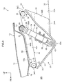
- the pop-up mechanism portion 30 is configured to include a hood hinge 32, which supports the hood 12 in such a way that the hood 12 can be opened and closed, and an actuator 50, which is actuated at the time of a collision with an impactor such as a pedestrian.
- a hood hinge 32 which supports the hood 12 in such a way that the hood 12 can be opened and closed
- an actuator 50 which is actuated at the time of a collision with an impactor such as a pedestrian.
- the hood 12 is configured to include a hood outer panel 14, which is placed on the vehicle outer side and configures a design surface, and a hood inner panel 16, which is placed on the engine compartment ER side and reinforces the hood outer panel 14. Additionally, the terminal portions of both are joined to each other by hemming. Furthermore, in a state in which the hood 12 is closing the engine compartment ER (the state shown in FIG. 3 ), the front end portion of the hood 12 is secured to the vehicle body by a hood lock not shown in the drawings.
- a bulging portion 18 is formed in the rear end side (rear portion side) of the hood inner panel 16.
- the bulging portion 18 bulges toward the vehicle lower side (the engine compartment ER) side with respect to the hood inner panel 16, and a bottom wall 18A of the bulging portion 18 is placed substantially parallel to the hood outer panel 14 as seen in a side sectional view.
- the hood hinge 32 is configured to include a hinge base 34 that is secured to the vehicle body, a swinging arm 36 that is rotatably coupled to the hinge base 34, and a hinge arm 44 that is secured to the hood 12.
- the hinge base 34 is formed in a substantially inverted L-shape as seen in a vehicle front view and is formed in a substantially V-shape (see FIG. 4 for details) that opens toward the vehicle upper side and obliquely forward as seen in a side view seen from inside in the vehicle width direction.
- the hinge base 34 is equipped with a plate-shaped attachment portion 34A that extends along the vehicle front and rear direction.
- the attachment portion 34A is secured to an upper surface portion 20A of a cowl top side 20, which is a vehicle body-side constituent member, in such a way that its plate thickness direction coincides with the substantially vehicle up and down direction.
- cowl top side 20 is disposed on both sides of a cowl that extends along the vehicle width direction between the rear end side of the hood 12 and the lower end portion of a windshield glass.
- the hinge base 34 is equipped with a support portion 34B, and the support portion 34B is bent toward the vehicle upper side from the vehicle width direction inside end portion of the attachment portion 34A and is formed in a plate shape whose plate thickness direction coincides with the substantially vehicle width direction.
- the swinging arm 36 is placed on the vehicle width direction inner side of the hinge base 34 and is formed in a substantially inverted triangular plate shape as seen in a side view. Specifically, as seen in a side view the swinging arm 36 is formed in a substantially inverted triangular plate shape having as a vertices a lower end portion 36A, a front end portion 36B placed on the vehicle front side and the vehicle upper side of the lower end portion 36A, and a rear end portion 36C placed on the vehicle rear side and the vehicle upper side of the lower end portion 36A.
- the rear end portion 36C of the swinging arm 36 is hinge-joined to the upper end portion of the support portion 34B of the hinge base 34 by a hinge pin 38 whose axial direction coincides with the vehicle width direction. Because of this, the swinging arm 36 is configured to be rotatable in the vehicle up and down direction (the direction of arrow A and the direction of arrow B in FIG. 3 ) using the hinge pin 38 as a rotational center.
- a coupling shaft 40 that rotatably supports the lower end portion of an actuator 50 described later is disposed in the lower end portion 36A of the swinging arm 36.
- the coupling shaft 40 is formed in a substantially cylindrical shape and projects inward in the vehicle width direction from the swinging arm 36 in such a way that its axial direction coincides with the vehicle width direction.
- a flange portion 42 is integrally formed on the outer peripheral portion of the swinging arm 36 in the section thereof excluding the upper edge interconnecting the front end portion 36B and the rear end portion 36C, and the flange portion 42 is bent inward in the vehicle width direction.
- the hinge arm 44 is placed on the vehicle width direction inner side of the swinging arm 36 and extends along the substantially vehicle front and rear direction. Specifically, the hinge arm 44 is equipped with a side wall portion 44A placed substantially parallel to the swinging arm 36. The front end portion of the side wall portion 44A is hinge-joined to the front end portion 36B of the swinging arm 36 by a hinge pin 46 whose axial direction coincides with the vehicle width direction. Because of this, the hinge arm 44 is configured to be relatively rotatable with respect to the swinging arm 36 in the vehicle up and down direction (the direction of arrow C and the direction of arrow D in FIG. 3 ) using the hinge pin 46 as a rotational center.
- the hinge arm 44 is equipped with a top wall portion 44B.
- the top wall portion 44B is formed bent inward in the vehicle width direction from the upper end portion of the side wall portion 44A and extends in the substantially vehicle front and rear direction along the undersurface of the bulging portion 18 of the hood 12.
- An attachment hole not shown in the drawings is formed through the top wall portion 44B, and in correspondence to the attachment hole a weld nut (not shown in the drawings) is secured to the bulging portion 18 of the hood 12.
- a hinge bolt not shown in the drawings is inserted inside the attachment hole from the vehicle lower side and is screwed into the weld nut, and thus the top wall portion 44B is fastened (secured) to the hood 12. Because of this, the hinge base 34 and the hood 12 are coupled to each other by the hinge arm 44 and the swinging arm 36.
- a coupling shaft 48 for coupling a piston rod 70 of the actuator 50 described later is integrally disposed on the rear end portion of the side wall portion 44A of the hinge arm 44.
- the coupling shaft 48 is formed in a substantially cylindrical shape and projects inward in the vehicle width direction from the side wall portion 44A.
- the hood hinge 32 is originally a hinge part for supporting the hood 12 on the body (vehicle body) in such a way that the hood 12 can be opened and closed, but in the present embodiment the hood hinge 32 is also a constituent element of the vehicle pop-up hood device 10. That is, when normally opening and closing the hood 12, the swinging arm 36 is rotated using the hinge pin 38 as a rotational center in a state in which relative rotation of the hinge arm 44 with respect to the swinging arm 36 is regulated by the actuator 50 described later.
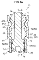
- the actuator 50 is placed on the vehicle width direction inner side of the swinging arm 36 and extends in such a way as to bridge the rear end portion of the hinge arm 44 and the lower end portion 36A of the swinging arm 36. That is to say, the actuator 50 is inclined toward the vehicle rear side heading toward the vehicle upper side as seen in a side view. Additionally, the actuator 50 has a cylinder 52, a piston rod 70 housed inside the cylinder 52, and a lock mechanism 80 (see FIG. 6 ).
- the cylinder 52 is configured to include a cylinder body 54, which is configured by a pipe having a substantially tubular shape, and a head portion 60 (see FIG. 5 ), which is disposed in the upper end portion of the cylinder body 54. Furthermore, an attachment bracket 66 is secured to the cylinder body 54.
- the attachment bracket 66 is formed in a substantially rectangular plate shape whose lengthwise direction coincides with the axial direction of the cylinder body 54 as seen in a side view and, seen from the lengthwise direction thereof, is bent in a substantially square U-shape that opens inward in the vehicle width direction. Additionally, the lower end portion of the attachment bracket 66 projects beyond the cylinder body 54 toward the vehicle lower side and is rotatably supported on the coupling shaft 40 of the swinging arm 36. Because of this, the lower end portion of the actuator 50 is configured to be relatively rotatable with respect to the swinging arm 36.
- an enlarged diameter portion 56 in which the head portion 60 described later is placed is formed in the upper end portion (the end portion on the side of the direction of arrow E in FIG. 5 ) of the cylinder body 54.
- a step portion 58 bent in a substantially crank shape outward in the radial direction of the cylinder body 54 as seen in a sectional view is formed in the upper end portion of the cylinder body 54, and because of this the enlarged diameter portion 56 having an enlarged diameter with respect to the cylinder body 54 is formed.
- a surface placed along a direction orthogonal to the axial direction of the cylinder 52 is an orthogonal surface 90 (see FIG. 6 for details) configuring a lock groove portion 86 of the lock mechanism 80 described later.
- a gas generation device 68 is disposed in the lower end portion (the end portion on the side of the direction of arrow F in FIG. 5 ) of the cylinder body 54.
- the gas generation device 68 is formed in a substantially cylindrical shape and is fitted inside the cylinder body 54 in such a way as to close off the lower end portion of the cylinder body 54.
- the gas generation device 68 is electrically connected to an ECU (control means) not shown in the drawings, and the ECU is electrically connected to a collision detection sensor that detects a collision with an impactor such as a pedestrian.
- the gas generation device 68 is configured to be actuated by the control of the ECU, and when the gas generation device 68 is actuated, a gas generated by the gas generation device 68 is supplied inside the cylinder body 54.
- the head portion 60 is formed in a substantially tubular shape and is placed coaxially inside the enlarged diameter portion 56 of the cylinder body 54. Furthermore, a swage groove portion 60A that opens outward in the radial direction of the head portion 60 is formed in the outer peripheral portion of the head portion 60. The swage groove portion 60A extends along the circumferential direction of the head portion 60 and is formed spanning the entire circumference of the head portion 60.
- part of the enlarged diameter portion 56 is swaged in such a way as to fit inside the swage groove portion 60A, and thus the cylinder body 54 and the head portion 60 are integrated. Because of this, a swage portion 56A is formed in the enlarged diameter portion 56 of the cylinder body 54 along the circumferential direction of the cylinder body 54.
- a circular pass-through hole 60B through which a rod portion 74 of the piston rod 70 described later is passed is formed through the axial center portion of the head portion 60.
- a housing recess portion 62 that opens toward the lower end side of the cylinder body 54 is formed in the lower end portion of the head portion 60.
- the housing recess portion 62 is formed in a circular shape as seen from the lower end side of the head portion 60, and the inner diameter dimension of the housing recess portion 62 is set slightly larger than the inner diameter dimension of the cylinder body 54.
- the piston rod 70 is formed in a substantially rod shape, is placed coaxially with the cylinder body 54, and is housed inside the cylinder body 54. Furthermore, the piston rod 70 is configured to include a piston portion 72, which configures the lower end portion of the piston rod 70, and a rod portion 74, which extends from the piston portion 72 along the axial direction of the cylinder 52 toward the vehicle upper side.
- the piston portion 72 is formed in a substantially cylindrical shape.
- the diameter dimension of the piston portion 72 is set slightly smaller than the inner diameter dimension of the housing recess portion 62 of the head portion 60 and the inner diameter dimension of the cylinder body 54, and the piston portion 72 is housed inside the cylinder body 54.
- a piston recess portion 72A that opens toward the lower end side of the cylinder body 54 is formed in the lower end portion of the piston portion 72.
- a seal groove portion 72B that opens outward in the radial direction of the piston portion 72 is formed in the outer peripheral portion of the lower end portion of the piston portion 72.
- the seal groove portion 72B extends along the circumferential direction of the piston portion 72 and is formed spanning the entire circumference of the piston portion 72.
- an O-ring 78 configured by a rubber material, for example, is placed inside the seal groove portion 72B, and the space between the piston portion 72 and the cylinder body 54 is sealed by the O-ring 78.
- the piston portion 72 (the piston rod 70) is raised toward the side in the direction of arrow E in FIG. 5 along the axial direction of the cylinder body 54 by the gas pressure inside the cylinder body 54. Furthermore, because the diameter dimension of the piston portion 72 is set smaller than the inner diameter dimension of the housing recess portion 62 of the head portion 60 as mentioned above, the upper portion of the piston portion 72 is configured in such a way that it can be placed inside the housing recess portion 62 when the piston rod 72 has risen (see FIG. 1B ).
- the rod portion 74 is formed in a cross-sectionally circular rod shape and extends from the piston portion 72 along the axial direction of the cylinder body 54 toward the vehicle upper side.
- the diameter dimension of the rod portion 74 is set slightly smaller than the inner diameter dimension of the pass-through hole 60B in the head portion 60, the rod portion 74 passes through the inside of the pass-through hole 60B, and the upper end portion of the rod portion 74 projects beyond the cylinder 52 toward the vehicle upper side.
- a rod coupling portion 76 is integrally disposed on the upper end portion of the rod portion 74, and the rod coupling portion 76 is formed in a substantially tubular shape whose axial direction coincides with the vehicle width direction. Additionally, the coupling shaft 48 of the hinge arm 44 is inserted inside the rod coupling portion 76, and the upper end portion of the rod portion 74 is coupled to the hinge arm 44 in such a way that it is relatively rotatable with respect to the hinge arm 44.
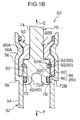
- the lock mechanism 80 is configured to include a housing groove portion 82 formed in the piston rod 70, a lock ring 84 disposed on the piston rod 70, and a lock groove portion 86 and a retention groove portion 92 formed in the cylinder 52.
- the housing groove portion 82 is formed in the outer peripheral portion of the upper portion of the piston portion 72 of the piston rod 70, extends along the circumferential direction of the piston portion 72, and is formed spanning the entire circumference of the piston portion 72. Furthermore, the housing groove portion 82 is formed in a cross-sectionally substantially trapezoidal shape that opens outward in the radial direction of the piston portion 72. Specifically, the housing groove portion 82 is configured to include a bottom surface 82A placed along the axial direction of the piston portion 72 as seen in a sectional view, an inclined surface 82B inclined toward the upper end side of the cylinder 52 (the side in the direction of arrow E in FIG.
- the lock ring 84 is configured by a wire made of metal having a cross-sectionally circular shape and is formed in a partially open annular shape. In other words, the lock ring 84 is formed in a substantially C-shape. Furthermore, the lock ring 84 is configured to be elastically deformable in its radial direction. Additionally, the lock ring 84 is reduced in diameter from its natural state (a state in which the lock ring 84 is not elastically deformed) and housed inside the housing groove portion 82 of the piston portion 72. That is to say, the lock ring 84 is placed between the housing groove portion 82 and the cylinder body 54.
- the lock groove portion 86 is configured by a step portion 88 formed in the housing recess portion 62 of the head portion 60 and an orthogonal surface 90 in the enlarged diameter portion 56 of the cylinder body 54.
- the step portion 88 is formed spanning the entire circumference of the open edge portion on the inner peripheral side of the housing recess portion 62, opens inward in the radial direction of the head portion 60, and opens toward the lower end side of the head portion 60.
- the step portion 88 is configured to include a bottom surface 8 8A placed along the axial direction of the head portion 60 as seen in a sectional view and an inclined surface 88B inclined toward the upper end side of the cylinder 52 heading inward in the radial direction of the head portion 60 from the upper end of the bottom surface 88A. Additionally, the step portion 88 is placed adjacent to the orthogonal surface 90 of the cylinder body 54 on the upper end side of the cylinder 52, and the lock groove portion 86 that opens inward in the radial direction of the head portion 60 is formed by the step portion 88 and the orthogonal surface 90.
- the lock ring 84 can fit inside the lock groove portion 86, and when the lock ring 84 has been fitted into the lock groove portion 86, movement (retraction) of the raised piston rod 70 toward the vehicle lower side is deterred. Specifically, the lock ring 84 becomes sandwiched between the inclined surface 82B of the housing groove portion 82 of the piston portion 72 and the orthogonal surface 90 of the lock groove portion 86, and movement of the piston rod 70 toward the vehicle lower side is deterred. Additionally, the position shown in FIG. 1C is a lock position and is a position at which the pushed-up hood 12 is finally supported by the actuator 50. It should be noted that movement of the piston rod 70 from the lock position toward the vehicle upper side is made possible as a result of the lock ring 84 being housed inside the housing groove portion 82 of the piston portion 72.
- the retention groove portion 92 is formed in the inner peripheral portion of the housing recess portion 62 of the head portion 60 and is placed more on the upper end side of the cylinder 52 than the step portion 88. That is, the lock groove portion 86 is placed on the vehicle lower side of the retention groove portion 92.
- the retention groove portion 92 extends along the circumferential direction of the head portion 60 and is formed spanning the entire circumference of the head portion 60. Furthermore, the retention groove portion 92 is formed in a cross-sectionally U-shape that opens inward in the radial direction of the head portion 60.
- the retention groove portion 92 is configured to include a bottom surface 92A placed along the axial direction of the head portion 60 as seen in a sectional view, an upper inclined surface 92B inclined toward the upper end side of the cylinder 52 heading inward in the radial direction of the head portion 60 from the upper end of the bottom surface 92A, and a lower inclined surface 92C inclined toward the lower end side of the cylinder 52 heading inward in the radial direction of the head portion 60 from the lower end of the bottom surface 92A.
- the lock ring 84 can be fitted into the retention groove portion 92, and the piston rod 70 becomes temporarily retained when the lock ring 84 has been fitted into the retention groove portion 92.
- the lock ring 84 fitted into the retention groove portion 92 comes into contact with the inclined surface 82B or the orthogonal surface 82C of the housing groove portion 82 of the piston portion 72, and thus movement of the piston portion 72 in the axial direction with respect to the cylinder 52 is limited. Because of this, the raised piston rod 70 is temporarily retained in a position (hereinafter this position will be called a "retention position") on the vehicle upper side of the lock position. It should be noted that in FIG.
- the lock ring 84 is shown away from the inclined surface 82B and the orthogonal surface 82C for the sake of convenience. Furthermore, in the retention position the upper surface of the piston portion 72 comes into contact with the bottom surface of the housing recess portion 62 of the head portion 60. Moreover, when a predetermined load toward the vehicle lower side acts on the piston rod 70 in the retention position, the lock ring 84 becomes elastically deformed in such a way as to become housed inside the housing groove portion 82 and the state in which the lock ring 84 is fitted into the retention groove portion 92 (the state in which the piston rod 70 is temporarily retained) becomes cancelled. This will be specifically described later, but the state in which the lock ring 84 is fitted into the retention groove portion 92 becomes cancelled at bottom dead center or near bottom dead center of the oscillation that occurs in the hood 12.
- the state shown in FIG. 3 is a non-actuated state of the vehicle pop-up hood device 10.
- the actuator 50 is in a non-actuated state, so most of the piston rod 70 is housed inside the cylinder body 54.
- the rod coupling portion 76 (the upper end portion) of the piston rod 70 is rotatably coupled to the coupling shaft 48 (the rear end portion) of the hinge arm 44.
- the fact that the vehicle has become involved in a frontal collision with an impactor is detected by the collision detection sensor and a collision signal is output to the ECU.
- the ECU judges whether or not it should actuate the vehicle pop-up hood device 10 on the basis of the collision signal that has been input, and when the ECU judges that it should actuate the vehicle pop-up hood device 10, an actuation signal is output to the actuator 50. Because of this, the gas generation device 68 of the actuator 50 is actuated and the gas is supplied inside the cylinder body 54.
- FIG. 7 schematically shows by means of a time series the state of the hood 12 seen from the vehicle rear side when the actuator 50 has pushed up the hood 12, and both vehicle width direction end portions of the hood 12 are indicated by unfilled circles.
- State (1) shown in FIG. 7 represents a state before the actuator 50 pushes up the hood 12. In this state, the actuator 50 is in a non-actuated state, so the piston portion 72 of the piston rod 70 is placed on the lower end side of the cylinder body 54.
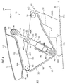
- the piston rod 70 (the piston portion 72) is instantaneously moved in its axial direction (see FIG. 1A ) and is raised to the retention position (see FIG. 1B ).
- the upper surface of the piston portion 72 is brought into contact with the bottom surface of the housing recess portion 62 of the head portion 60.
- the lock ring 84 housed inside the housing groove portion 82 of the piston portion 72 becomes elastically deformed outward in its radial direction and fitted into the retention groove portion 92 of the head portion 60.
- the inclined surface 82B of the housing groove portion 82 of the piston portion 72 comes into contact with the lock ring 84 and movement of the piston rod 70 toward the vehicle lower side (the side in the direction of arrow F in FIG. 1 ) is limited. Because of this, the piston rod 70 is temporarily retained in the retention position.
- the displacement of the vehicle width direction central portion of the hood 12 in the vehicle up and down direction is not limited, so the vehicle width direction central portion of the pushed-up hood 12 becomes displaced toward the vehicle upper side of the retention position by the force of inertia. Furthermore, the displacement of both vehicle width direction end portions of the hood 12 toward the vehicle upper side is limited by the actuator 50. For this reason, at the point in time when the vehicle width direction central portion of the hood 12 has reached top dead center (see state (4) in FIG. 7 ), the vehicle width direction central portion of the hood 12 undergoes a reversal to being displaced toward the vehicle lower side due to reaction. Because of this, seen from the vehicle rear side, the hood 12 tends to undergo simple harmonic motion in such a way that the vehicle width direction central portion of the hood 12 becomes an antinode and both vehicle width direction end portions of the hood 12 become nodes.
- the vehicle width direction central portion of the hood 12 that becomes displaced toward the vehicle lower side due to reaction passes from top dead center through the retention position and becomes displaced to bottom dead center (the point at which the hood 12 goes from being displaced toward the vehicle lower side to being displaced toward the vehicle upper side) side (see state (5) in FIG. 7 ).
- the lock ring 84 is fitted into the retention groove portion 92 and the state in which the piston rod 70 is temporarily retained by the lock mechanism 80 is maintained. That is to say, both vehicle width direction end portions of the hood 12 are placed in the retention position.
- the lock ring 84 that has been moved to the lock position becomes elastically deformed outward in its radial direction and fitted into the lock groove portion 86 of the cylinder 52. Additionally, the lock ring 84 becomes sandwiched between the inclined surface 82B of the housing groove portion 82 of the piston portion 72 and the orthogonal surface 90 of the cylinder 52, and movement of the piston portion 72 toward the vehicle lower side is deterred.
- the piston rod 70 can be raised to the retention position on the vehicle upper side of the lock position. Furthermore, the piston rod 70 that has been raised to the retention position is temporarily retained by the lock mechanism 80 disposed in the actuator 50 (see FIG. 1B ). Additionally, as mentioned above, when, during oscillation of the hood 12 that occurs after the hood 12 has been pushed up by the actuator 50, the vehicle width direction central portion of the hood 12 becomes displaced from top dead center toward the vehicle lower side and reaches bottom dead center or near bottom dead center, the state in which the piston rod 70 is temporarily retained by the lock mechanism 80 becomes cancelled and both vehicle width direction end portions of the hood 12 become displaced to the lock positon (see FIG.
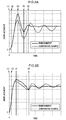
- FIG. 8A and FIG. 8B Data in which the present embodiment is compared to a comparative example in regard to this point are shown below in FIG. 8A and FIG. 8B .
- the retention groove portion 92 of the lock mechanism 80 in the present embodiment is omitted.
- the movement, toward the vehicle upper side, of the piston portion 72 raised to the lock position is limited.
- FIG. 8A shows, together with the comparative example, the oscillation waveform in the vehicle width direction central portion of the rear end portion of the hood 12, with the oscillation waveform indicted by the solid line being the oscillation waveform of the present embodiment and the oscillation waveform indicated by the dashed line being the oscillation waveform of the comparative example.
- FIG. 8A shows, together with the comparative example, the oscillation waveform in the vehicle width direction central portion of the rear end portion of the hood 12, with the oscillation waveform indicted by the solid line being the oscillation waveform of the present embodiment and the oscillation waveform indicated by the dashed line being the oscillation waveform
- FIG. 8B shows, together with the comparative example, the oscillation waveform in both vehicle width direction end portions (directly over the pop-up mechanism portions 30) of the rear end portion of the hood 12, with the oscillation waveform indicted by the solid line being the oscillation waveform of the present embodiment and the oscillation waveform indicated by the dashed line being the oscillation waveform of the comparative example.
- the horizontal axis represents time and the vertical axis represents displacement.
- points in time (1) to (6) shown in FIG. 8A and FIG. 8B correspond to states (1) to (6) in FIG. 7 .
- the amplitude (swing) in the vehicle width direction central portion of the hood 12 when the vehicle width direction central portion of the hood 12 has been displaced to bottom dead center (point in time (5) in FIG. 8A ) is greatly reduced compared to the comparative example.
- the amplitude of the vehicle width direction central portion of the hood 12 becomes smaller than in the comparative example after the cancellation of the state in which the piston rod 70 is temporarily retained by the lock mechanism 80 (after point in time (6) in FIG. 8A ).
- FIG. 8A shows that the amplitude of the vehicle width direction central portion of the hood 12 when the vehicle width direction central portion of the hood 12 has been displaced to bottom dead center (point in time (5) in FIG. 8A )
- the amplitude of the vehicle width direction central portion of the hood 12 becomes smaller than in the comparative example after the cancellation of the state in which the piston rod 70 is temporarily retained by the lock mechanism 80 (after point in time (6) in FIG. 8A ).
- the amplitude of both vehicle width direction end portions of the hood 12 becomes smaller than in the comparative example after the cancellation of the state in which the piston rod 70 is temporarily retained by the lock mechanism 80 (after point in time (6) in FIG. 8B ). Because of this, the oscillation that has occurred in the hood 12 can be damped at an early stage.
- the retention groove portion 92 is formed in (the head portion 60 of) the cylinder 52, in the retention position the lock ring 84 becomes fitted into the retention groove portion 92, and the piston portion 72 (the piston rod 70) is temporarily retained in the retention position. For this reason, the efficiency with which the piston rod 70 is temporarily retained in the retention position can be enhanced with a simple configuration. Furthermore, by appropriately adjusting the shape and depth of the retention groove portion 92, the timing when the state in which the piston rod 70 is temporarily retained in bottom dead center or near bottom dead center becomes cancelled, for example, can be easily adjusted.
- the lock groove portion 86 is formed in the cylinder 52, and in the lock position the lock ring 84 becomes fitted into the lock groove portion 86. For this reason, movement, toward the vehicle upper side, of the lock ring 84 that has been moved from the retention position to the lock position can be prevented. Because of this, the lock ring 84 is kept from moving again toward the retention position side due to a rebound, so rebounding of the hood 12 in the lock position can be prevented.
- the lock groove portion 86 is configured by the step portion 88 formed in the head portion 60 and the orthogonal surface 90 formed in the cylinder body 54
- the step portion 88 may also be omitted from the head portion 60 as shown in FIG. 9 .
- the lock ring 84 in the lock position the lock ring 84 becomes sandwiched by the inclined surface 82B (not shown in FIG. 9 ) of the housing groove portion 82 in the piston portion 72 and the orthogonal surface 90 of the cylinder body 54 and thus movement of the piston rod 70 toward the vehicle lower side can be limited.
- the cross-sectional shape of the retention groove portion 92 is formed in a substantially U-shape, but the cross-sectional shape of the retention groove portion 92 is not limited to this.
- the upper inclined surface 92B of the retention groove portion 92 may be placed in a direction orthogonal to the axial direction of the cylinder 52, so that the cross-sectional shape of the retention groove portion 92 is formed in a substantially trapezoidal shape.
- the hood hinge 32 is configured to include the hinge base 34, the swinging arm 36, and the hinge arm 44, but the swinging arm 36 may also be omitted from the hood hinge 32. That is to say, the hood hinge 32 may be configured in such a way that the hinge arm 44 is rotatably coupled to the hood hinge 32, the actuator 50 is secured to the vehicle body or the hinge base 34, and the hood 12 or the hinge arm 44 is pushed up by the piston rod 70.
- the actuator 50 is configured to push up both vehicle width direction end portions of the rear end portion of the hood 12, but the actuator 50 may also be applied to a type of vehicle in which the front end portion of the hood 12 is pushed up.
- the actuator 50 may also be configured in such a way that the actuator 50 is secured to the vehicle body and the front end portion of the hood 12 is pushed up by the actuator 50.
Landscapes
- Engineering & Computer Science (AREA)
- Mechanical Engineering (AREA)
- Physics & Mathematics (AREA)
- Fluid Mechanics (AREA)
- General Engineering & Computer Science (AREA)
- Chemical & Material Sciences (AREA)
- Combustion & Propulsion (AREA)
- Transportation (AREA)
- Superstructure Of Vehicle (AREA)
Applications Claiming Priority (2)
| Application Number | Priority Date | Filing Date | Title |
|---|---|---|---|
| JP2014005745A JP5915671B2 (ja) | 2014-01-16 | 2014-01-16 | 車両用ポップアップフード装置 |
| PCT/JP2014/081289 WO2015107778A1 (ja) | 2014-01-16 | 2014-11-26 | 車両用ポップアップフード装置 |
Publications (3)
| Publication Number | Publication Date |
|---|---|
| EP3095680A1 true EP3095680A1 (de) | 2016-11-23 |
| EP3095680A4 EP3095680A4 (de) | 2017-01-04 |
| EP3095680B1 EP3095680B1 (de) | 2019-05-01 |
Family
ID=53542682
Family Applications (1)
| Application Number | Title | Priority Date | Filing Date |
|---|---|---|---|
| EP14878872.2A Not-in-force EP3095680B1 (de) | 2014-01-16 | 2014-11-26 | Fahrzeugaufstellhaubenvorrichtung |
Country Status (5)
| Country | Link |
|---|---|
| EP (1) | EP3095680B1 (de) |
| JP (1) | JP5915671B2 (de) |
| KR (1) | KR101747280B1 (de) |
| CN (1) | CN105793144B (de) |
| WO (1) | WO2015107778A1 (de) |
Cited By (2)
| Publication number | Priority date | Publication date | Assignee | Title |
|---|---|---|---|---|
| AT522245A4 (de) * | 2019-07-26 | 2020-09-15 | Hirtenberger Automotive Safety Gmbh & Co Kg | Aktuator, insbesondere zum Anstellen von Motorhauben |
| AT524574B1 (de) * | 2021-02-01 | 2022-07-15 | Astotec Automotive Gmbh | Aktuator zum Anheben einer Motorhaube |
Families Citing this family (5)
| Publication number | Priority date | Publication date | Assignee | Title |
|---|---|---|---|---|
| JP6308185B2 (ja) * | 2015-08-26 | 2018-04-11 | トヨタ自動車株式会社 | 車両用ポップアップフード装置のアクチュエータ及び車両用ポップアップフード装置 |
| KR101755878B1 (ko) | 2015-11-03 | 2017-07-07 | 현대자동차주식회사 | 셀프 락킹방식 액추에이터 및 이를 이용한 팝업 후드 장치 |
| CN110466471A (zh) * | 2019-08-22 | 2019-11-19 | 陕西庆华汽车安全系统有限公司 | 一种汽车引擎盖顶起装置及其顶起方法 |
| CN110979250A (zh) * | 2019-12-06 | 2020-04-10 | 浙江吉利汽车研究院有限公司 | 一种举升器 |
| CN114312653B (zh) * | 2021-12-20 | 2023-05-05 | 均胜均安汽车电子(上海)有限公司 | 一种汽车引擎盖的起爆器 |
Family Cites Families (14)
| Publication number | Priority date | Publication date | Assignee | Title |
|---|---|---|---|---|
| JPS61282171A (ja) * | 1985-06-07 | 1986-12-12 | Nissan Motor Co Ltd | 自動車のリヤホイ−ルハウス構造 |
| JP3674296B2 (ja) | 1998-03-19 | 2005-07-20 | 日産自動車株式会社 | 自動車のフード跳ね上げ装置 |
| JP2004322735A (ja) * | 2003-04-22 | 2004-11-18 | Nhk Spring Co Ltd | アクチュエータ |
| FR2878213A1 (fr) * | 2004-11-22 | 2006-05-26 | Pyroalliance Sa | Systemes d'absorption mecaniques pour articulation active de capot |
| JP2008056120A (ja) * | 2006-08-31 | 2008-03-13 | Toyoda Gosei Co Ltd | 歩行者保護装置 |
| US7374008B1 (en) * | 2007-05-08 | 2008-05-20 | Gm Global Technology Operations, Inc. | Hood elevation system |
| JP4973412B2 (ja) | 2007-09-14 | 2012-07-11 | 日産自動車株式会社 | 自動車のフード跳ね上げ装置及びフード跳ね上げ方法 |
| JP4941401B2 (ja) * | 2008-04-28 | 2012-05-30 | 豊田合成株式会社 | アクチュエータ |
| JP2010236637A (ja) * | 2009-03-31 | 2010-10-21 | Toyoda Gosei Co Ltd | アクチュエータ |
| JP5136527B2 (ja) * | 2009-08-31 | 2013-02-06 | 豊田合成株式会社 | アクチュエータ |
| JP5257395B2 (ja) * | 2010-03-30 | 2013-08-07 | 豊田合成株式会社 | アクチュエータ |
| CN103476642B (zh) * | 2011-04-18 | 2016-03-23 | 奥托立夫开发公司 | 发动机罩举升装置 |
| KR101755711B1 (ko) * | 2011-10-04 | 2017-07-10 | 현대자동차주식회사 | 차량의 쇽업소버 장착부 구조 |
| JP2013139169A (ja) * | 2011-12-28 | 2013-07-18 | Toyota Motor Corp | 車両後部構造 |
-
2014
- 2014-01-16 JP JP2014005745A patent/JP5915671B2/ja not_active Expired - Fee Related
- 2014-11-26 KR KR1020167016338A patent/KR101747280B1/ko not_active Expired - Fee Related
- 2014-11-26 CN CN201480065404.7A patent/CN105793144B/zh not_active Expired - Fee Related
- 2014-11-26 EP EP14878872.2A patent/EP3095680B1/de not_active Not-in-force
- 2014-11-26 WO PCT/JP2014/081289 patent/WO2015107778A1/ja not_active Ceased
Cited By (4)
| Publication number | Priority date | Publication date | Assignee | Title |
|---|---|---|---|---|
| AT522245A4 (de) * | 2019-07-26 | 2020-09-15 | Hirtenberger Automotive Safety Gmbh & Co Kg | Aktuator, insbesondere zum Anstellen von Motorhauben |
| AT522245B1 (de) * | 2019-07-26 | 2020-09-15 | Hirtenberger Automotive Safety Gmbh & Co Kg | Aktuator, insbesondere zum Anstellen von Motorhauben |
| AT524574B1 (de) * | 2021-02-01 | 2022-07-15 | Astotec Automotive Gmbh | Aktuator zum Anheben einer Motorhaube |
| AT524574A4 (de) * | 2021-02-01 | 2022-07-15 | Astotec Automotive Gmbh | Aktuator zum Anheben einer Motorhaube |
Also Published As
| Publication number | Publication date |
|---|---|
| EP3095680A4 (de) | 2017-01-04 |
| JP5915671B2 (ja) | 2016-05-11 |
| JP2015134519A (ja) | 2015-07-27 |
| CN105793144A (zh) | 2016-07-20 |
| EP3095680B1 (de) | 2019-05-01 |
| WO2015107778A1 (ja) | 2015-07-23 |
| CN105793144B (zh) | 2018-04-03 |
| KR20160088400A (ko) | 2016-07-25 |
| KR101747280B1 (ko) | 2017-06-14 |
Similar Documents
| Publication | Publication Date | Title |
|---|---|---|
| EP3095680B1 (de) | Fahrzeugaufstellhaubenvorrichtung | |
| US9708010B2 (en) | Vehicle pop-up hood device | |
| US9764711B2 (en) | Vehicle pop-up hood device | |
| US20170057458A1 (en) | Vehicle pop-up hood device | |
| JP4410823B2 (ja) | 車両用ポップアップフード装置 | |
| JP6245235B2 (ja) | 車両用ポップアップフード装置 | |
| JP2015145209A (ja) | 車両用ポップアップフード装置 | |
| JP5799994B2 (ja) | 車両用ポップアップフード装置 | |
| JP6003848B2 (ja) | 車両用ポップアップフード装置 | |
| JP6032191B2 (ja) | 車両用ポップアップフード装置 | |
| JP5644727B2 (ja) | アクチュエータ | |
| JP6102790B2 (ja) | 車両用ポップアップフード装置 | |
| JP6287790B2 (ja) | フード跳ね上げ装置 | |
| JP2016083957A (ja) | 車両用ポップアップフード装置 | |
| JP2020090162A (ja) | フード支持構造 | |
| JP2004352125A (ja) | 閉鎖部材の開放操作装置 | |
| JP6221925B2 (ja) | 車両用ポップアップフード装置 | |
| JP2017100678A (ja) | 車両用ポップアップフード装置 | |
| JP2017056776A (ja) | 車両用ポップアップフード装置 | |
| JP2011143819A (ja) | 車両用ポップアップフード装置 | |
| JP2009202862A (ja) | フード跳ね上げ装置 | |
| JP2015214280A (ja) | 車両用ポップアップフード装置 |
Legal Events
| Date | Code | Title | Description |
|---|---|---|---|
| PUAI | Public reference made under article 153(3) epc to a published international application that has entered the european phase |
Free format text: ORIGINAL CODE: 0009012 |
|
| 17P | Request for examination filed |
Effective date: 20160616 |
|
| AK | Designated contracting states |
Kind code of ref document: A1 Designated state(s): AL AT BE BG CH CY CZ DE DK EE ES FI FR GB GR HR HU IE IS IT LI LT LU LV MC MK MT NL NO PL PT RO RS SE SI SK SM TR |
|
| AX | Request for extension of the european patent |
Extension state: BA ME |
|
| A4 | Supplementary search report drawn up and despatched |
Effective date: 20161201 |
|
| RIC1 | Information provided on ipc code assigned before grant |
Ipc: B60R 21/38 20110101ALI20161125BHEP Ipc: B62D 25/10 20060101AFI20161125BHEP |
|
| DAX | Request for extension of the european patent (deleted) | ||
| STAA | Information on the status of an ep patent application or granted ep patent |
Free format text: STATUS: EXAMINATION IS IN PROGRESS |
|
| 17Q | First examination report despatched |
Effective date: 20180326 |
|
| GRAP | Despatch of communication of intention to grant a patent |
Free format text: ORIGINAL CODE: EPIDOSNIGR1 |
|
| STAA | Information on the status of an ep patent application or granted ep patent |
Free format text: STATUS: GRANT OF PATENT IS INTENDED |
|
| INTG | Intention to grant announced |
Effective date: 20181017 |
|
| GRAS | Grant fee paid |
Free format text: ORIGINAL CODE: EPIDOSNIGR3 |
|
| GRAA | (expected) grant |
Free format text: ORIGINAL CODE: 0009210 |
|
| STAA | Information on the status of an ep patent application or granted ep patent |
Free format text: STATUS: THE PATENT HAS BEEN GRANTED |
|
| RIN1 | Information on inventor provided before grant (corrected) |
Inventor name: NARITA, SOHTARO Inventor name: FUKASAWA, AKIHITO |
|
| RIN1 | Information on inventor provided before grant (corrected) |
Inventor name: FUKASAWA, AKIHITO Inventor name: NARITA, SOHTARO |
|
| AK | Designated contracting states |
Kind code of ref document: B1 Designated state(s): AL AT BE BG CH CY CZ DE DK EE ES FI FR GB GR HR HU IE IS IT LI LT LU LV MC MK MT NL NO PL PT RO RS SE SI SK SM TR |
|
| REG | Reference to a national code |
Ref country code: GB Ref legal event code: FG4D |
|
| REG | Reference to a national code |
Ref country code: CH Ref legal event code: EP Ref country code: AT Ref legal event code: REF Ref document number: 1126555 Country of ref document: AT Kind code of ref document: T Effective date: 20190515 |
|
| REG | Reference to a national code |
Ref country code: DE Ref legal event code: R096 Ref document number: 602014046018 Country of ref document: DE |
|
| REG | Reference to a national code |
Ref country code: IE Ref legal event code: FG4D |
|
| REG | Reference to a national code |
Ref country code: DE Ref legal event code: R084 Ref document number: 602014046018 Country of ref document: DE |
|
| REG | Reference to a national code |
Ref country code: GB Ref legal event code: 746 Effective date: 20190716 |
|
| REG | Reference to a national code |
Ref country code: NL Ref legal event code: MP Effective date: 20190501 |
|
| REG | Reference to a national code |
Ref country code: LT Ref legal event code: MG4D |
|
| PG25 | Lapsed in a contracting state [announced via postgrant information from national office to epo] |
Ref country code: FI Free format text: LAPSE BECAUSE OF FAILURE TO SUBMIT A TRANSLATION OF THE DESCRIPTION OR TO PAY THE FEE WITHIN THE PRESCRIBED TIME-LIMIT Effective date: 20190501 Ref country code: NO Free format text: LAPSE BECAUSE OF FAILURE TO SUBMIT A TRANSLATION OF THE DESCRIPTION OR TO PAY THE FEE WITHIN THE PRESCRIBED TIME-LIMIT Effective date: 20190801 Ref country code: AL Free format text: LAPSE BECAUSE OF FAILURE TO SUBMIT A TRANSLATION OF THE DESCRIPTION OR TO PAY THE FEE WITHIN THE PRESCRIBED TIME-LIMIT Effective date: 20190501 Ref country code: SE Free format text: LAPSE BECAUSE OF FAILURE TO SUBMIT A TRANSLATION OF THE DESCRIPTION OR TO PAY THE FEE WITHIN THE PRESCRIBED TIME-LIMIT Effective date: 20190501 Ref country code: PT Free format text: LAPSE BECAUSE OF FAILURE TO SUBMIT A TRANSLATION OF THE DESCRIPTION OR TO PAY THE FEE WITHIN THE PRESCRIBED TIME-LIMIT Effective date: 20190901 Ref country code: NL Free format text: LAPSE BECAUSE OF FAILURE TO SUBMIT A TRANSLATION OF THE DESCRIPTION OR TO PAY THE FEE WITHIN THE PRESCRIBED TIME-LIMIT Effective date: 20190501 Ref country code: HR Free format text: LAPSE BECAUSE OF FAILURE TO SUBMIT A TRANSLATION OF THE DESCRIPTION OR TO PAY THE FEE WITHIN THE PRESCRIBED TIME-LIMIT Effective date: 20190501 Ref country code: LT Free format text: LAPSE BECAUSE OF FAILURE TO SUBMIT A TRANSLATION OF THE DESCRIPTION OR TO PAY THE FEE WITHIN THE PRESCRIBED TIME-LIMIT Effective date: 20190501 Ref country code: ES Free format text: LAPSE BECAUSE OF FAILURE TO SUBMIT A TRANSLATION OF THE DESCRIPTION OR TO PAY THE FEE WITHIN THE PRESCRIBED TIME-LIMIT Effective date: 20190501 |
|
| PG25 | Lapsed in a contracting state [announced via postgrant information from national office to epo] |
Ref country code: BG Free format text: LAPSE BECAUSE OF FAILURE TO SUBMIT A TRANSLATION OF THE DESCRIPTION OR TO PAY THE FEE WITHIN THE PRESCRIBED TIME-LIMIT Effective date: 20190801 Ref country code: RS Free format text: LAPSE BECAUSE OF FAILURE TO SUBMIT A TRANSLATION OF THE DESCRIPTION OR TO PAY THE FEE WITHIN THE PRESCRIBED TIME-LIMIT Effective date: 20190501 Ref country code: GR Free format text: LAPSE BECAUSE OF FAILURE TO SUBMIT A TRANSLATION OF THE DESCRIPTION OR TO PAY THE FEE WITHIN THE PRESCRIBED TIME-LIMIT Effective date: 20190802 Ref country code: LV Free format text: LAPSE BECAUSE OF FAILURE TO SUBMIT A TRANSLATION OF THE DESCRIPTION OR TO PAY THE FEE WITHIN THE PRESCRIBED TIME-LIMIT Effective date: 20190501 |
|
| REG | Reference to a national code |
Ref country code: AT Ref legal event code: MK05 Ref document number: 1126555 Country of ref document: AT Kind code of ref document: T Effective date: 20190501 |
|
| PG25 | Lapsed in a contracting state [announced via postgrant information from national office to epo] |
Ref country code: IS Free format text: LAPSE BECAUSE OF FAILURE TO SUBMIT A TRANSLATION OF THE DESCRIPTION OR TO PAY THE FEE WITHIN THE PRESCRIBED TIME-LIMIT Effective date: 20190901 |
|
| PG25 | Lapsed in a contracting state [announced via postgrant information from national office to epo] |
Ref country code: SK Free format text: LAPSE BECAUSE OF FAILURE TO SUBMIT A TRANSLATION OF THE DESCRIPTION OR TO PAY THE FEE WITHIN THE PRESCRIBED TIME-LIMIT Effective date: 20190501 Ref country code: RO Free format text: LAPSE BECAUSE OF FAILURE TO SUBMIT A TRANSLATION OF THE DESCRIPTION OR TO PAY THE FEE WITHIN THE PRESCRIBED TIME-LIMIT Effective date: 20190501 Ref country code: CZ Free format text: LAPSE BECAUSE OF FAILURE TO SUBMIT A TRANSLATION OF THE DESCRIPTION OR TO PAY THE FEE WITHIN THE PRESCRIBED TIME-LIMIT Effective date: 20190501 Ref country code: DK Free format text: LAPSE BECAUSE OF FAILURE TO SUBMIT A TRANSLATION OF THE DESCRIPTION OR TO PAY THE FEE WITHIN THE PRESCRIBED TIME-LIMIT Effective date: 20190501 Ref country code: AT Free format text: LAPSE BECAUSE OF FAILURE TO SUBMIT A TRANSLATION OF THE DESCRIPTION OR TO PAY THE FEE WITHIN THE PRESCRIBED TIME-LIMIT Effective date: 20190501 Ref country code: EE Free format text: LAPSE BECAUSE OF FAILURE TO SUBMIT A TRANSLATION OF THE DESCRIPTION OR TO PAY THE FEE WITHIN THE PRESCRIBED TIME-LIMIT Effective date: 20190501 |
|
| REG | Reference to a national code |
Ref country code: DE Ref legal event code: R097 Ref document number: 602014046018 Country of ref document: DE |
|
| PG25 | Lapsed in a contracting state [announced via postgrant information from national office to epo] |
Ref country code: SM Free format text: LAPSE BECAUSE OF FAILURE TO SUBMIT A TRANSLATION OF THE DESCRIPTION OR TO PAY THE FEE WITHIN THE PRESCRIBED TIME-LIMIT Effective date: 20190501 Ref country code: IT Free format text: LAPSE BECAUSE OF FAILURE TO SUBMIT A TRANSLATION OF THE DESCRIPTION OR TO PAY THE FEE WITHIN THE PRESCRIBED TIME-LIMIT Effective date: 20190501 |
|
| PLBE | No opposition filed within time limit |
Free format text: ORIGINAL CODE: 0009261 |
|
| STAA | Information on the status of an ep patent application or granted ep patent |
Free format text: STATUS: NO OPPOSITION FILED WITHIN TIME LIMIT |
|
| PG25 | Lapsed in a contracting state [announced via postgrant information from national office to epo] |
Ref country code: TR Free format text: LAPSE BECAUSE OF FAILURE TO SUBMIT A TRANSLATION OF THE DESCRIPTION OR TO PAY THE FEE WITHIN THE PRESCRIBED TIME-LIMIT Effective date: 20190501 |
|
| 26N | No opposition filed |
Effective date: 20200204 |
|
| PG25 | Lapsed in a contracting state [announced via postgrant information from national office to epo] |
Ref country code: PL Free format text: LAPSE BECAUSE OF FAILURE TO SUBMIT A TRANSLATION OF THE DESCRIPTION OR TO PAY THE FEE WITHIN THE PRESCRIBED TIME-LIMIT Effective date: 20190501 |
|
| PG25 | Lapsed in a contracting state [announced via postgrant information from national office to epo] |
Ref country code: SI Free format text: LAPSE BECAUSE OF FAILURE TO SUBMIT A TRANSLATION OF THE DESCRIPTION OR TO PAY THE FEE WITHIN THE PRESCRIBED TIME-LIMIT Effective date: 20190501 |
|
| REG | Reference to a national code |
Ref country code: CH Ref legal event code: PL |
|
| PG25 | Lapsed in a contracting state [announced via postgrant information from national office to epo] |
Ref country code: LI Free format text: LAPSE BECAUSE OF NON-PAYMENT OF DUE FEES Effective date: 20191130 Ref country code: CH Free format text: LAPSE BECAUSE OF NON-PAYMENT OF DUE FEES Effective date: 20191130 Ref country code: LU Free format text: LAPSE BECAUSE OF NON-PAYMENT OF DUE FEES Effective date: 20191126 Ref country code: MC Free format text: LAPSE BECAUSE OF FAILURE TO SUBMIT A TRANSLATION OF THE DESCRIPTION OR TO PAY THE FEE WITHIN THE PRESCRIBED TIME-LIMIT Effective date: 20190501 |
|
| REG | Reference to a national code |
Ref country code: BE Ref legal event code: MM Effective date: 20191130 |
|
| PG25 | Lapsed in a contracting state [announced via postgrant information from national office to epo] |
Ref country code: IE Free format text: LAPSE BECAUSE OF NON-PAYMENT OF DUE FEES Effective date: 20191126 |
|
| PG25 | Lapsed in a contracting state [announced via postgrant information from national office to epo] |
Ref country code: BE Free format text: LAPSE BECAUSE OF NON-PAYMENT OF DUE FEES Effective date: 20191130 |
|
| PG25 | Lapsed in a contracting state [announced via postgrant information from national office to epo] |
Ref country code: CY Free format text: LAPSE BECAUSE OF FAILURE TO SUBMIT A TRANSLATION OF THE DESCRIPTION OR TO PAY THE FEE WITHIN THE PRESCRIBED TIME-LIMIT Effective date: 20190501 |
|
| PG25 | Lapsed in a contracting state [announced via postgrant information from national office to epo] |
Ref country code: HU Free format text: LAPSE BECAUSE OF FAILURE TO SUBMIT A TRANSLATION OF THE DESCRIPTION OR TO PAY THE FEE WITHIN THE PRESCRIBED TIME-LIMIT; INVALID AB INITIO Effective date: 20141126 Ref country code: MT Free format text: LAPSE BECAUSE OF FAILURE TO SUBMIT A TRANSLATION OF THE DESCRIPTION OR TO PAY THE FEE WITHIN THE PRESCRIBED TIME-LIMIT Effective date: 20190501 |
|
| PGFP | Annual fee paid to national office [announced via postgrant information from national office to epo] |
Ref country code: FR Payment date: 20211109 Year of fee payment: 8 Ref country code: DE Payment date: 20211005 Year of fee payment: 8 Ref country code: GB Payment date: 20211007 Year of fee payment: 8 |
|
| PG25 | Lapsed in a contracting state [announced via postgrant information from national office to epo] |
Ref country code: MK Free format text: LAPSE BECAUSE OF FAILURE TO SUBMIT A TRANSLATION OF THE DESCRIPTION OR TO PAY THE FEE WITHIN THE PRESCRIBED TIME-LIMIT Effective date: 20190501 |
|
| REG | Reference to a national code |
Ref country code: DE Ref legal event code: R119 Ref document number: 602014046018 Country of ref document: DE |
|
| GBPC | Gb: european patent ceased through non-payment of renewal fee |
Effective date: 20221126 |
|
| PG25 | Lapsed in a contracting state [announced via postgrant information from national office to epo] |
Ref country code: GB Free format text: LAPSE BECAUSE OF NON-PAYMENT OF DUE FEES Effective date: 20221126 Ref country code: DE Free format text: LAPSE BECAUSE OF NON-PAYMENT OF DUE FEES Effective date: 20230601 |
|
| PG25 | Lapsed in a contracting state [announced via postgrant information from national office to epo] |
Ref country code: FR Free format text: LAPSE BECAUSE OF NON-PAYMENT OF DUE FEES Effective date: 20221130 |