EP3095679B1 - Verkleidungsstruktur für ein fahrzeug - Google Patents
Verkleidungsstruktur für ein fahrzeug Download PDFInfo
- Publication number
- EP3095679B1 EP3095679B1 EP16169477.3A EP16169477A EP3095679B1 EP 3095679 B1 EP3095679 B1 EP 3095679B1 EP 16169477 A EP16169477 A EP 16169477A EP 3095679 B1 EP3095679 B1 EP 3095679B1
- Authority
- EP
- European Patent Office
- Prior art keywords
- vehicle
- cowl
- width direction
- vehicle width
- extension section
- Prior art date
- Legal status (The legal status is an assumption and is not a legal conclusion. Google has not performed a legal analysis and makes no representation as to the accuracy of the status listed.)
- Not-in-force
Links
- XLYOFNOQVPJJNP-UHFFFAOYSA-N water Substances O XLYOFNOQVPJJNP-UHFFFAOYSA-N 0.000 claims description 60
- 239000011521 glass Substances 0.000 claims description 19
- 230000000149 penetrating effect Effects 0.000 claims description 6
- 238000007789 sealing Methods 0.000 description 18
- 230000001012 protector Effects 0.000 description 6
- 230000000694 effects Effects 0.000 description 4
- 239000000853 adhesive Substances 0.000 description 3
- 230000001070 adhesive effect Effects 0.000 description 3
- 238000003466 welding Methods 0.000 description 3
- JOYRKODLDBILNP-UHFFFAOYSA-N Ethyl urethane Chemical compound CCOC(N)=O JOYRKODLDBILNP-UHFFFAOYSA-N 0.000 description 2
- 238000004378 air conditioning Methods 0.000 description 2
- 230000000052 comparative effect Effects 0.000 description 2
- 238000005516 engineering process Methods 0.000 description 2
- 230000005484 gravity Effects 0.000 description 2
- 239000002184 metal Substances 0.000 description 2
- 238000012986 modification Methods 0.000 description 1
- 230000004048 modification Effects 0.000 description 1
- 238000005192 partition Methods 0.000 description 1
- 230000002093 peripheral effect Effects 0.000 description 1
- 239000011347 resin Substances 0.000 description 1
- 229920005989 resin Polymers 0.000 description 1
Images


Classifications
-
- B—PERFORMING OPERATIONS; TRANSPORTING
- B62—LAND VEHICLES FOR TRAVELLING OTHERWISE THAN ON RAILS
- B62D—MOTOR VEHICLES; TRAILERS
- B62D25/00—Superstructure or monocoque structure sub-units; Parts or details thereof not otherwise provided for
- B62D25/08—Front or rear portions
- B62D25/081—Cowls
-
- B—PERFORMING OPERATIONS; TRANSPORTING
- B62—LAND VEHICLES FOR TRAVELLING OTHERWISE THAN ON RAILS
- B62D—MOTOR VEHICLES; TRAILERS
- B62D25/00—Superstructure or monocoque structure sub-units; Parts or details thereof not otherwise provided for
- B62D25/08—Front or rear portions
-
- B—PERFORMING OPERATIONS; TRANSPORTING
- B62—LAND VEHICLES FOR TRAVELLING OTHERWISE THAN ON RAILS
- B62D—MOTOR VEHICLES; TRAILERS
- B62D25/00—Superstructure or monocoque structure sub-units; Parts or details thereof not otherwise provided for
- B62D25/24—Superstructure sub-units with access or drainage openings having movable or removable closures; Sealing means therefor
Definitions
- the present disclosure relates to a cowl structure for a vehicle.
- Fig. 4 of Japanese Patent Application Laid-Open ( JP-A) No. 2012-86606 illustrates technology related to a protector that includes a rain gutter further to a vehicle rear side than a rear edge portion of a cowl louver.
- the protector of this related art includes a location into which a rear edge portion of the cowl louver is fitted, and a location into which a lower edge of a windshield is inserted; and the above-described rain gutter juts out to the vehicle rear side and is disposed at the lower side of the windshield.
- the rain gutter is set at a position capable of receiving water that has been channeled along a sealing portion between a back face of the windshield and the cowl (not illustrated in Fig. 4 of Patent Document 1), and that the rain gutter is set such that water is made to fall from a position offset in the vehicle width direction with respect to a vehicle width direction forming range of an inlet port set at the lower side of a lower end portion of the windshield, intrusion of the water into the inlet port can be prevented or reduced.
- the protector must be attached to the cowl louver and set with the rain gutter, and in cases in which there is a long distance from a rear edge portion of the cowl louver to the sealing portion between the back face of the windshield and the cowl, the protector must jut out by a large amount toward the vehicle rear side.
- a length direction i.e., a vehicle width direction
- the water may fall from a vehicle width direction position corresponding to the vehicle width direction forming range of the inlet port.
- JP2011-240797 A which is considered as the closest prior art, discloses a cowl structure according to the preamble of independent claim 1 with a gutter channel ( Fig. 1A , ref. 13) extending forwards of the glass-supporting upper cowl portion ( Fig. 1A ref. 5).
- an object of the present disclosure is, with a simple structure, to obtain a cowl structure for a vehicle capable of preventing or effectively reducing intrusion of water into an inlet port set at the lower side of a lower end portion of a windshield.
- a cowl structure for a vehicle includes: a cowl main body that has a length disposed in a vehicle width direction running along a lower edge of a windshield, that is formed with a gutter shape open to a vehicle upper side, the cowl main body comprising a rear wall portion that is formed with an inlet port penetrating the rear wall portion for drawing outside air into the vehicle cabin, and that includes a glass support portion for supporting, through a seal portion, a lower end portion of the windshield from a vehicle lower side; and a gutter extension section that extends from a front end portion of the glass support portion toward a vehicle front lower side, that has a length disposed in the vehicle width direction, that is formed in a gutter shape open to the vehicle upper side, that is set in a range of the vehicle width direction containing a vehicle width direction forming range of the inlet port, and that includes a water drainage structure configured to cause received water to fall from a position offset in the vehicle width direction with respect to the vehicle width direction forming range of the inlet port
- the lower end portion of the windshield is supported from the vehicle lower side by the glass support portion of the cowl main body through the seal portion, and the inlet port is formed penetrating the rear wall portion of the cowl main body. If water is channeled along the seal portion between the lower end portion of the windshield and the glass support portion of the cowl main body, there is accordingly a possibility of this water attempting to flow toward the lower side at a vehicle width direction position corresponding to the vehicle width direction forming range of the inlet port.
- the gutter extension section is formed extended from a front end portion of the glass support portion toward the vehicle front lower side.
- the gutter extension section is disposed with its length direction in the vehicle width direction, is formed in a gutter shape open to the vehicle upper side, and is set in a range of the vehicle width direction containing the vehicle width direction forming range of the inlet port. Even supposing water that had been channeled along the sealing portion were then to flow toward the lower side at a vehicle width direction position corresponding to the vehicle width direction forming range of the inlet port, this water would thereby flow toward the outside of the vehicle width direction range corresponding to the vehicle width direction forming range of the inlet port due to the water flowing to the gutter extension section and flowing along the length direction of the gutter extension section. The water would then fall from a position offset in the vehicle width direction with respect to the vehicle width direction forming range of the inlet port due to this water drainage structure.
- a cowl structure according to a second aspect is the first aspect, wherein an inclined portion for draining water, which is inclined toward a vehicle lower side on progression toward a length direction terminal side of the gutter extension section serves, as the water drainage structure and is set at both length direction end portions of a bottom portion of the gutter extension section.
- the inclined portion for draining water inclined toward the vehicle lower side on progression toward the length direction terminal side of the gutter extension section and serving as the water drainage structure, is set at both length direction end portions of the bottom portion of the gutter extension section.
- the water that has flowed into the gutter extension section can accordingly be made to consistently fall from the length direction terminal of the gutter extension section.
- the present disclosure also provides a vehicle, such as an automobile, comprising a cowl structure according to the first or second aspects.
- the vehicle includes a vehicle cabin and a windshield.
- the vehicle may include an air conditioning unit configured to condition the air inside the vehicle cabin.
- the cowl structure of the present disclosure has the excellent advantageous effect of being capable of, with a simple structure, preventing or effectively reducing intrusion of water into the inlet port set at the lower side of the lower end portion of the windshield.
- arrow FR indicates the vehicle front side
- arrow UP indicates the vehicle upper side
- arrow W indicates the vehicle width direction, as appropriate.
- front-rear and up-down directions refers to front-rear in the vehicle front-rear direction, and up-down in the vehicle up-down direction.
- Fig. 1 is a perspective view illustrating a portion of a vehicle 10 (e.g., an automobile) applied with a cowl structure according to the present exemplary embodiment, as viewed obliquely from the vehicle upper front.
- a vehicle 10 e.g., an automobile
- a cowl structure according to the present exemplary embodiment
- the outer profile of a windshield (i.e., front windshield glass) 12 is illustrated by double-dotted intermittent lines, and a hood, a cowl louver, wiper arms, and the like, are omitted from illustration.
- Fig. 2 is an enlarged vertical cross-section illustrating a state sectioned along line 2-2 in Fig. 1 .
- a cowl louver 18 made, e.g., of resin and a cowl 20 made, e.g., of sheet metal are disposed adjacent to a lower end portion 12A of the windshield 12.
- the cowl louver 18 and the cowl 20 are disposed along the lower edge of the windshield 12, with their length direction running in the vehicle width direction.
- the cowl louver 18 is disposed at the vehicle upper side of a location at the vehicle front side of the cowl 20, and is penetrated by plural small openings, not illustrated in the drawings.
- the cowl louver 18 is adjacent to the vehicle lower side of a rear end portion of a hood 15, and a sealing member 16 made, e.g., of rubber is fitted to a vehicle rear side end portion of the cowl louver 18.
- the sealing member 16 is in press-contact with a front side lower end portion of a glass face of the windshield 12.
- the cowl 20 links together left and right front pillars 14 (see Fig. 1 ), has a function of separating water from air attempting to flow inside a vehicle cabin 40, and houses a wiper system (not illustrated in the drawings) within its cross-section.
- the cowl 20 includes a cowl main body 20A.
- the cowl main body 20A is formed in a gutter shape open to the vehicle upper side.
- An inlet port 24H for drawing outside air into the vehicle cabin 40 is formed penetrating a rear wall portion 24B of the cowl main body 20A.
- the cowl main body 20A includes part of a cowl upper panel 22 (a portion excluding a gutter extension section 20B, described later), a cowl inner panel 24, and a cowl lower panel 26. Note that the cowl upper panel 22, cowl inner panel 24, and cowl lower panel 26 are preferably all sheet metal components.
- the cowl upper panel 22 is disposed running along a lower face of the lower end portion 12A of the windshield 12 with its length direction in the vehicle width direction.
- the cowl upper panel 22 includes a glass support portion 22A forming an attachment face (i.e., a support face) for the lower end portion 12A of the windshield 12.
- the glass support portion 22A is disposed parallel to the lower end portion 12A of the windshield 12, and supports the lower end portion 12A of the windshield 12 from the vehicle lower side through a sealing portion 28.
- the sealing portion 28 is made of a urethane-based adhesive, and affixes the windshield 12 and the glass support portion 22A together.
- the sealing portion 28 extends in a line substantially along the length direction of the cowl upper panel 22.
- Fig. 1 illustrates a first seal portion 28A and a second seal portion 28B that are slightly separated from each other as the sealing portion 28.
- the first seal portion 28A is set in a line on a vehicle width direction intermediate portion of the glass support portion 22A
- most of the second seal portion 28B is set in a line on an extension line of the first seal portion 28A toward the vehicle width direction outside.
- End portions of the first seal portion 28A and the second seal portion 28B are disposed side-by-side with a slight interval in the vehicle front-rear direction therebetween.
- a vehicle width direction inside end portion of the second seal portion 28B is bent in a crank shape as viewed from the vehicle upper side, and is disposed alongside the first seal portion 28A at the vehicle front side thereof.
- a vehicle width direction outside location of the sealing portion 28 i.e., the second seal portion 28B
- a sealing portion 30 sealing between the front pillar 14 and the windshield 12 is set in a line continuing at the vehicle rear side of the sealing portion 28.
- Fig. 3 illustrates an enlarged vertical cross-section in a state sectioned along line 3-3 in Fig. 1 .
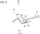
- the sealing portion 30 affixes a lower side of a side portion of the windshield 12 to an upper face of an inside flange 14F of a side outer panel 14A forming part of the front pillar 14, and as an example, is made of a urethane-based adhesive.
- the side outer panel 14A includes a pillar outer main body 14H disposed at the vehicle width direction outside of the windshield 12 and bulging out toward the vehicle cabin outside, and the inside flange 14F that extends bent from an end portion on the vehicle width direction inside of the pillar outer main body 14H toward the vehicle width direction inside.
- a gap 13, into which water 50 is capable of flowing, is formed between the pillar outer main body 14H and a vehicle width direction outside end face of the windshield 12.
- the cowl upper panel 22 includes a rear side wall portion 22B that is extended bent from a rear end portion of the glass support portion 22A obliquely toward the vehicle lower rear side, and also includes a rear end flange 22C that is extended bent from a lower end portion of the rear side wall portion 22B obliquely toward the vehicle upper rear side.
- a rear end flange 24A of the cowl inner panel 24 is superimposed on a lower face of the rear end flange 22C and is joined thereto, e.g., by welding such as spot welding. Note that configuration of a front end portion (i.e., a location further toward the front side than the glass support portion 22A) of the cowl upper panel 22 is described later.
- the cowl inner panel 24 is disposed with its length direction in the vehicle width direction, similarly to the cowl upper panel 22.
- the cowl inner panel 24 includes the rear wall portion 24B (i.e., the rear wall portion 24B of the cowl main body 20A) that extends bent from the front end portion of the rear end flange 24A obliquely toward the vehicle lower front side.
- a flange 34F of an air conditioner duct 34 at the outer periphery portion of the inlet port 24H is fastened to the rear face of the rear wall portion 24B, and a seal is interposed between the rear wall portion 24B and the flange 34F.
- the air conditioner duct 34 forms a portion of an airflow path of an air conditioner (i.e., an air conditioning unit that conditions the air inside the vehicle cabin 40), and a blower, not illustrated in the drawings, is disposed inside the airflow path.
- the cowl inner panel 24 also includes a bottom wall portion 24C extended bent from a lower end portion of the rear wall portion 24B obliquely toward the vehicle front lower side. A lower face of the bottom wall portion 24C is joined to an upper end portion 32A of a dash panel 32 (i.e., a vehicle passenger compartment front wall). The cowl inner panel 24 is thereby supported by the dash panel 32.
- the dash panel 32 partitions between a power unit chamber 38 and the vehicle passenger compartment (i.e., the vehicle cabin 40).
- a rear end portion 26F of the cowl lower panel 26 is affixed to and sealed to an upper face of the bottom wall portion 24C of the cowl inner panel 24 using an adhesive 36.
- the cowl lower panel 26 is disposed with its length direction in the vehicle width direction, similarly to the cowl upper panel 22 and the cowl inner panel 24, and a non-illustrated front side lower end portion of the cowl louver 18 is attached to a front end flange 26A (see Fig. 1 ).
- the cowl lower panel 26 includes a rear side inclined portion 26E extending bent from a front end of the rear end portion 26F obliquely toward the vehicle lower front side, and also includes a front portion bottom wall portion 26D extending bent from a lower end portion of the rear side inclined portion 26E toward the vehicle front side.
- the cowl lower panel 26 also includes a front side inclined portion 26C extending bent from a front end portion of the front portion bottom wall portion 26D obliquely toward the vehicle upper front side, and a shelf portion 26B extending bent from an upper end portion of the front side inclined portion 26C toward the vehicle front side.
- the cowl 20 includes the gutter extension section 20B (i.e., the rain gutter) extended from a front end portion of the glass support portion 22A of the cowl main body 20A (i.e., the cowl upper panel 22) of the upper portion of the cowl 20 toward the vehicle front lower side.
- the gutter extension section 20B is disposed with its length direction in the vehicle width direction, is formed in a gutter shape open to the vehicle upper side, and is set in a range of the vehicle width direction containing a vehicle width direction forming range of the inlet port 24H. Namely, as illustrated in Fig.
- a length direction intermediate portion of the gutter extension section 20B is provided within a vehicle width direction range coinciding with the vehicle width direction forming range of the inlet port 24H, and both length direction sides of the gutter extension section 20B are provided at positions outside of the vehicle width direction forming range of the inlet port 24H in the vehicle width direction.
- the length direction central portion of the gutter extension section 20B is set at the vehicle front lower side of a portion where the end portions of the first seal portion 28A and the second seal portion 28B are side-by-side in the vehicle front-rear direction.
- the lower end portion 12A of the windshield 12 is supported from the vehicle lower side by the glass support portion 22A of the cowl main body 20A through the sealing portion 28, and the inlet port 24H is formed penetrating the rear wall portion 24B of the cowl main body 20A.
- the inlet port 24H is formed penetrating the rear wall portion 24B of the cowl main body 20A.
- the gutter extension section 20B is formed extended from a front end portion of the glass support portion 22A toward the vehicle front lower side, and the gutter extension section 20B is disposed with its length direction in the vehicle width direction, is formed in a gutter shape open to the vehicle upper side, and is set in a range of the vehicle width direction containing the vehicle width direction forming range of the inlet port 24H.
- the inclined portions 22S for draining water, inclined toward the vehicle lower side on progression toward the length direction terminal sides of the gutter extension section 20B and serving as a water drainage structure configured to cause water received by the gutter extension section 20B to fall from positions offset in the vehicle width direction with respect to the vehicle width direction forming range of the inlet port 24H, are set at both length direction end portions of the bottom portion 22Z of the gutter extension section 20B.
- the flow speed of the water 50 increases when the water 50 reaches a length direction end portion of the gutter extension section 20B.
- the water 50 that has reached the length direction terminal of the gutter extension section 20B can be prevented from trickling around to the lower face side of the gutter extension section 20B due to the surface tension by using a simple structure, even if the amount of water 50 that has flowed into the gutter extension section 20B is small.
- the water 50 that has flowed into the gutter extension section 20B can be made to consistently fall from the length direction terminal of the gutter extension section 20B, namely, can be made to consistently fall from a position offset in the vehicle width direction with respect to the vehicle width direction forming range of the inlet port 24H.
- cowl structure of the present exemplary embodiment is capable of reducing such costs, and is also superior to the comparative structure from the perspective of weight.
- the inclined portions 22S for draining water illustrated in Fig. 4 and so on serve as water drainage structures; however, other water drainage structures may be applied as water drainage structures, such as a water drainage rib (or protrusion) hanging down toward the vehicle lower side (in the direction of gravity) from a length direction terminal of the bottom portion of the gutter extension section, or a water drainage structure including a water drainage hole penetrating the bottom portion of the gutter extension section and a water drainage tube portion hanging down toward the vehicle lower side (in the direction of gravity) from an outer peripheral side of the water drainage holes.
- a water drainage rib or protrusion
- a water drainage structure including a water drainage hole penetrating the bottom portion of the gutter extension section and a water drainage tube portion hanging down toward the vehicle lower side (in the direction of gravity) from an outer peripheral side of the water drainage holes.
Landscapes
- Engineering & Computer Science (AREA)
- Chemical & Material Sciences (AREA)
- Combustion & Propulsion (AREA)
- Transportation (AREA)
- Mechanical Engineering (AREA)
- Body Structure For Vehicles (AREA)
Claims (3)
- Motorhaubenstruktur (20) für ein Fahrzeug (10), das eine Fahrzeugkabine (40) und eine Windschutzscheibe (12) umfasst, wobei die Motorhaubenstruktur (20) umfasst:einen Motorhaubenhauptteil (20A), der eine Länge aufweist, die in einer Fahrzeugbreitenrichtung (W) angeordnet ist, die entlang einer Unterkante der Windschutzscheibe (12) verläuft, und der mit einer Wasserrinnenform gebildet ist, die sich zu einer Fahrzeugoberseite öffnet, wobei der Motorhaubenhauptteil (20A) einen hinteren Wandabschnitt (24B) umfasst, der mit einem Einlassanschluss (24H) gebildet ist, der den hinteren Wandabschnitt (24B) durchdringt, um Außenluft in die Fahrzeugkabine (40) zu saugen, wobei der Motorhaubenhauptteil (20A) einen Glasstützabschnitt (22A) beinhaltet, um über einen Dichtungsabschnitt (28) einen unteren Endabschnitt (12A) der Windschutzscheibe (12) von einer Fahrzeugunterseite aus zu stützen, undeinen Wasserrinnen-Erweiterungsabschnitt (20B), der sich von einem vorderen Endabschnitt des Glasstützabschnitts (22A) hin zu einer Fahrzeugfront-Unterseite erstreckt, der eine Länge aufweist, die in der Fahrzeugbreitenrichtung (W) angeordnet ist, und der in einer Wasserrinnenform gebildet ist, die sich zur Fahrzeugoberseite öffnet, dadurch gekennzeichnet, dass der Wasserrinnen-Erweiterungsabschnitt (20B) in einem Bereich der Fahrzeugbreitenrichtung (W) eingerichtet ist, der einen die Fahrzeugbreitenrichtung bildenden Bereich des Einlassanschlusses (24H) bildet, und dadurch, dass der Wasserrinnen-Erweiterungsabschnitt (20B) eine Wasserableitungsstruktur (22S) beinhaltet, die dafür ausgelegt ist, aufgenommenes Wasser zu veranlassen, von einer Position, die in Bezug auf den die Fahrzeugbreitenrichtung bildenden Bereich des Einlassanschlusses (24H) in der Fahrzeugbreitenrichtung (W) versetzt ist, herabzufallen.
- Motorhaubenstruktur (20) nach Anspruch 1, wobei ein geneigter Abschnitt (22S) zum Ableiten von Wasser, der hin zu einer Fahrzeugunterseite im Verlauf hin zu einer Längsrichtungs-Endseite des Wasserrinnen-Erweiterungsabschnittes (20B) geneigt ist, als die Wasserableitungsstruktur (22S) dient und an beiden längsrichtungsseitigen Endabschnitten eines Bodenabschnitts (22Z) des Wasserrinnen-Erweiterungsabschnittes (20B) eingerichtet ist.
- Fahrzeug (10), umfassend die Motorhaubenstruktur (20) nach Anspruch 1 oder 2.
Applications Claiming Priority (1)
| Application Number | Priority Date | Filing Date | Title |
|---|---|---|---|
| JP2015101392A JP6636720B2 (ja) | 2015-05-18 | 2015-05-18 | カウル構造 |
Publications (2)
| Publication Number | Publication Date |
|---|---|
| EP3095679A1 EP3095679A1 (de) | 2016-11-23 |
| EP3095679B1 true EP3095679B1 (de) | 2018-10-17 |
Family
ID=55970877
Family Applications (1)
| Application Number | Title | Priority Date | Filing Date |
|---|---|---|---|
| EP16169477.3A Not-in-force EP3095679B1 (de) | 2015-05-18 | 2016-05-13 | Verkleidungsstruktur für ein fahrzeug |
Country Status (4)
| Country | Link |
|---|---|
| US (1) | US9623913B2 (de) |
| EP (1) | EP3095679B1 (de) |
| JP (1) | JP6636720B2 (de) |
| CN (1) | CN106167050B (de) |
Families Citing this family (10)
| Publication number | Priority date | Publication date | Assignee | Title |
|---|---|---|---|---|
| FR3072332B1 (fr) * | 2017-10-13 | 2021-08-06 | Psa Automobiles Sa | Vehicule comprenant une traverse inferieure de baie de pare-brise pourvue d’un dispositif d’evacutation d’eau. |
| CN108397331B (zh) * | 2018-03-15 | 2022-05-24 | 刘京依 | 一种用于冬季汽车低温启动的智能机器人 |
| JP6846461B2 (ja) * | 2019-05-31 | 2021-03-24 | 本田技研工業株式会社 | カウルトップ構造 |
| JP7167868B2 (ja) * | 2019-07-02 | 2022-11-09 | 住友電装株式会社 | ワイヤハーネス用プロテクタ |
| JP7625945B2 (ja) * | 2021-04-05 | 2025-02-04 | マツダ株式会社 | 車両の前部構造 |
| JP7613216B2 (ja) | 2021-04-05 | 2025-01-15 | マツダ株式会社 | 車両の前部構造 |
| JP7746733B2 (ja) | 2021-08-23 | 2025-10-01 | マツダ株式会社 | 車両の前部構造 |
| JP7487715B2 (ja) * | 2021-09-21 | 2024-05-21 | トヨタ車体株式会社 | 車両用フードのシール構造 |
| USD1015961S1 (en) * | 2022-04-14 | 2024-02-27 | Zhejiang ZEEKR Automobile Research & DevCo., Ltd. | Air grille for cowl of a vehicle |
| US12606248B2 (en) * | 2022-11-30 | 2026-04-21 | Nissan North America, Inc. | Vehicle cowl assembly |
Family Cites Families (15)
| Publication number | Priority date | Publication date | Assignee | Title |
|---|---|---|---|---|
| US7000979B2 (en) | 2003-12-22 | 2006-02-21 | Nissan Technical Center North America, Inc. | Vehicle cowl structure with vent pipe |
| JP2007326385A (ja) * | 2006-06-06 | 2007-12-20 | Mazda Motor Corp | 自動車の前部構造 |
| JP4492689B2 (ja) * | 2007-12-07 | 2010-06-30 | 日産自動車株式会社 | 自動車のカウル構造 |
| JP2010228717A (ja) * | 2009-03-30 | 2010-10-14 | Daihatsu Motor Co Ltd | 車両における車体前部構造 |
| JP5601018B2 (ja) * | 2010-05-18 | 2014-10-08 | スズキ株式会社 | 車両のカウル部構造 |
| CN101947978B (zh) * | 2010-09-19 | 2012-03-28 | 奇瑞汽车股份有限公司 | 一种具有防水结构的汽车后围板总成 |
| JP2012086606A (ja) | 2010-10-18 | 2012-05-10 | Kojima Press Industry Co Ltd | カウルルーバー用プロテクター |
| JP5594887B2 (ja) * | 2010-10-26 | 2014-09-24 | ダイハツ工業株式会社 | 車両の車体前部構造 |
| CN101973316B (zh) * | 2010-11-22 | 2012-03-28 | 奇瑞汽车股份有限公司 | 一种前围上盖板结构 |
| CN103347774B (zh) | 2011-02-24 | 2015-03-25 | 丰田自动车株式会社 | 汽车用前围部结构 |
| JP2013060158A (ja) * | 2011-09-14 | 2013-04-04 | Daihatsu Motor Co Ltd | 車両の車体前部構造 |
| US8567851B2 (en) * | 2011-09-23 | 2013-10-29 | Nissan North America, Inc. | Vehicle cowl cover |
| JP5910091B2 (ja) * | 2012-01-11 | 2016-04-27 | スズキ株式会社 | カウル部構造 |
| CN102658836A (zh) * | 2012-04-16 | 2012-09-12 | 奇瑞汽车股份有限公司 | 一种前舱流水槽总成及其安装方法 |
| JP2015085781A (ja) * | 2013-10-30 | 2015-05-07 | ダイハツ工業株式会社 | 車両の外気導入装置 |
-
2015
- 2015-05-18 JP JP2015101392A patent/JP6636720B2/ja not_active Expired - Fee Related
-
2016
- 2016-05-10 US US15/150,881 patent/US9623913B2/en not_active Expired - Fee Related
- 2016-05-13 EP EP16169477.3A patent/EP3095679B1/de not_active Not-in-force
- 2016-05-13 CN CN201610320180.0A patent/CN106167050B/zh not_active Expired - Fee Related
Non-Patent Citations (1)
| Title |
|---|
| None * |
Also Published As
| Publication number | Publication date |
|---|---|
| JP2016215755A (ja) | 2016-12-22 |
| CN106167050A (zh) | 2016-11-30 |
| US20160339962A1 (en) | 2016-11-24 |
| US9623913B2 (en) | 2017-04-18 |
| EP3095679A1 (de) | 2016-11-23 |
| JP6636720B2 (ja) | 2020-01-29 |
| CN106167050B (zh) | 2018-10-16 |
Similar Documents
| Publication | Publication Date | Title |
|---|---|---|
| US9623913B2 (en) | Cowl structure | |
| US7976097B2 (en) | Cowl structure of vehicle | |
| US9085324B2 (en) | Front pillar structure for vehicle | |
| JP6144742B2 (ja) | 車両の風切音低減構造 | |
| US9056632B2 (en) | Motor vehicle with radiator tank assembly | |
| US20100237660A1 (en) | Covering part | |
| US8220864B2 (en) | Front structure for a motor vehicle | |
| JPWO2015152096A1 (ja) | 車両用カウル構造 | |
| KR920005377B1 (ko) | 차량의 앞부분의 차체구조 | |
| CN206067919U (zh) | 用于车辆的通风盖板组件和具有其的车辆 | |
| US20090058139A1 (en) | Vehicle Body Structure | |
| US9573559B2 (en) | Front body structure of vehicle | |
| CN107757725B (zh) | 汽车的整流构造 | |
| JP2009051328A (ja) | ピラートリムの排水路構造 | |
| US20220281289A1 (en) | Cowl grille structure of vehicle | |
| US11981371B2 (en) | Front structure of vehicle | |
| JP6630975B2 (ja) | 車体前部構造 | |
| CN101927679A (zh) | 一种汽车暖风机压力室板的流水槽 | |
| JP2015085781A (ja) | 車両の外気導入装置 | |
| JP2010006314A (ja) | 自動車の換気構造 | |
| JP5428434B2 (ja) | カウルトップガーニッシュのシール構造 | |
| JP2022131150A (ja) | 車両用カウル構造 | |
| US12017703B2 (en) | Front structure of vehicle | |
| CN209904695U (zh) | 通风盖板及汽车 | |
| JP2005067569A (ja) | 自動車の外気導入装置 |
Legal Events
| Date | Code | Title | Description |
|---|---|---|---|
| PUAI | Public reference made under article 153(3) epc to a published international application that has entered the european phase |
Free format text: ORIGINAL CODE: 0009012 |
|
| 17P | Request for examination filed |
Effective date: 20160513 |
|
| AK | Designated contracting states |
Kind code of ref document: A1 Designated state(s): AL AT BE BG CH CY CZ DE DK EE ES FI FR GB GR HR HU IE IS IT LI LT LU LV MC MK MT NL NO PL PT RO RS SE SI SK SM TR |
|
| AX | Request for extension of the european patent |
Extension state: BA ME |
|
| GRAP | Despatch of communication of intention to grant a patent |
Free format text: ORIGINAL CODE: EPIDOSNIGR1 |
|
| STAA | Information on the status of an ep patent application or granted ep patent |
Free format text: STATUS: GRANT OF PATENT IS INTENDED |
|
| INTG | Intention to grant announced |
Effective date: 20171117 |
|
| GRAJ | Information related to disapproval of communication of intention to grant by the applicant or resumption of examination proceedings by the epo deleted |
Free format text: ORIGINAL CODE: EPIDOSDIGR1 |
|
| STAA | Information on the status of an ep patent application or granted ep patent |
Free format text: STATUS: REQUEST FOR EXAMINATION WAS MADE |
|
| INTC | Intention to grant announced (deleted) | ||
| GRAP | Despatch of communication of intention to grant a patent |
Free format text: ORIGINAL CODE: EPIDOSNIGR1 |
|
| STAA | Information on the status of an ep patent application or granted ep patent |
Free format text: STATUS: GRANT OF PATENT IS INTENDED |
|
| INTG | Intention to grant announced |
Effective date: 20180502 |
|
| GRAS | Grant fee paid |
Free format text: ORIGINAL CODE: EPIDOSNIGR3 |
|
| GRAA | (expected) grant |
Free format text: ORIGINAL CODE: 0009210 |
|
| STAA | Information on the status of an ep patent application or granted ep patent |
Free format text: STATUS: THE PATENT HAS BEEN GRANTED |
|
| AK | Designated contracting states |
Kind code of ref document: B1 Designated state(s): AL AT BE BG CH CY CZ DE DK EE ES FI FR GB GR HR HU IE IS IT LI LT LU LV MC MK MT NL NO PL PT RO RS SE SI SK SM TR |
|
| REG | Reference to a national code |
Ref country code: GB Ref legal event code: FG4D |
|
| REG | Reference to a national code |
Ref country code: CH Ref legal event code: EP |
|
| REG | Reference to a national code |
Ref country code: DE Ref legal event code: R096 Ref document number: 602016006375 Country of ref document: DE |
|
| REG | Reference to a national code |
Ref country code: IE Ref legal event code: FG4D |
|
| REG | Reference to a national code |
Ref country code: AT Ref legal event code: REF Ref document number: 1053656 Country of ref document: AT Kind code of ref document: T Effective date: 20181115 |
|
| REG | Reference to a national code |
Ref country code: DE Ref legal event code: R084 Ref document number: 602016006375 Country of ref document: DE |
|
| REG | Reference to a national code |
Ref country code: GB Ref legal event code: 746 Effective date: 20181228 |
|
| REG | Reference to a national code |
Ref country code: NL Ref legal event code: MP Effective date: 20181017 |
|
| REG | Reference to a national code |
Ref country code: LT Ref legal event code: MG4D |
|
| REG | Reference to a national code |
Ref country code: AT Ref legal event code: MK05 Ref document number: 1053656 Country of ref document: AT Kind code of ref document: T Effective date: 20181017 |
|
| PG25 | Lapsed in a contracting state [announced via postgrant information from national office to epo] |
Ref country code: NL Free format text: LAPSE BECAUSE OF FAILURE TO SUBMIT A TRANSLATION OF THE DESCRIPTION OR TO PAY THE FEE WITHIN THE PRESCRIBED TIME-LIMIT Effective date: 20181017 |
|
| PG25 | Lapsed in a contracting state [announced via postgrant information from national office to epo] |
Ref country code: LV Free format text: LAPSE BECAUSE OF FAILURE TO SUBMIT A TRANSLATION OF THE DESCRIPTION OR TO PAY THE FEE WITHIN THE PRESCRIBED TIME-LIMIT Effective date: 20181017 Ref country code: ES Free format text: LAPSE BECAUSE OF FAILURE TO SUBMIT A TRANSLATION OF THE DESCRIPTION OR TO PAY THE FEE WITHIN THE PRESCRIBED TIME-LIMIT Effective date: 20181017 Ref country code: HR Free format text: LAPSE BECAUSE OF FAILURE TO SUBMIT A TRANSLATION OF THE DESCRIPTION OR TO PAY THE FEE WITHIN THE PRESCRIBED TIME-LIMIT Effective date: 20181017 Ref country code: AT Free format text: LAPSE BECAUSE OF FAILURE TO SUBMIT A TRANSLATION OF THE DESCRIPTION OR TO PAY THE FEE WITHIN THE PRESCRIBED TIME-LIMIT Effective date: 20181017 Ref country code: PL Free format text: LAPSE BECAUSE OF FAILURE TO SUBMIT A TRANSLATION OF THE DESCRIPTION OR TO PAY THE FEE WITHIN THE PRESCRIBED TIME-LIMIT Effective date: 20181017 Ref country code: NO Free format text: LAPSE BECAUSE OF FAILURE TO SUBMIT A TRANSLATION OF THE DESCRIPTION OR TO PAY THE FEE WITHIN THE PRESCRIBED TIME-LIMIT Effective date: 20190117 Ref country code: LT Free format text: LAPSE BECAUSE OF FAILURE TO SUBMIT A TRANSLATION OF THE DESCRIPTION OR TO PAY THE FEE WITHIN THE PRESCRIBED TIME-LIMIT Effective date: 20181017 Ref country code: IS Free format text: LAPSE BECAUSE OF FAILURE TO SUBMIT A TRANSLATION OF THE DESCRIPTION OR TO PAY THE FEE WITHIN THE PRESCRIBED TIME-LIMIT Effective date: 20190217 Ref country code: BG Free format text: LAPSE BECAUSE OF FAILURE TO SUBMIT A TRANSLATION OF THE DESCRIPTION OR TO PAY THE FEE WITHIN THE PRESCRIBED TIME-LIMIT Effective date: 20190117 Ref country code: FI Free format text: LAPSE BECAUSE OF FAILURE TO SUBMIT A TRANSLATION OF THE DESCRIPTION OR TO PAY THE FEE WITHIN THE PRESCRIBED TIME-LIMIT Effective date: 20181017 |
|
| PG25 | Lapsed in a contracting state [announced via postgrant information from national office to epo] |
Ref country code: GR Free format text: LAPSE BECAUSE OF FAILURE TO SUBMIT A TRANSLATION OF THE DESCRIPTION OR TO PAY THE FEE WITHIN THE PRESCRIBED TIME-LIMIT Effective date: 20190118 Ref country code: RS Free format text: LAPSE BECAUSE OF FAILURE TO SUBMIT A TRANSLATION OF THE DESCRIPTION OR TO PAY THE FEE WITHIN THE PRESCRIBED TIME-LIMIT Effective date: 20181017 Ref country code: SE Free format text: LAPSE BECAUSE OF FAILURE TO SUBMIT A TRANSLATION OF THE DESCRIPTION OR TO PAY THE FEE WITHIN THE PRESCRIBED TIME-LIMIT Effective date: 20181017 Ref country code: AL Free format text: LAPSE BECAUSE OF FAILURE TO SUBMIT A TRANSLATION OF THE DESCRIPTION OR TO PAY THE FEE WITHIN THE PRESCRIBED TIME-LIMIT Effective date: 20181017 Ref country code: PT Free format text: LAPSE BECAUSE OF FAILURE TO SUBMIT A TRANSLATION OF THE DESCRIPTION OR TO PAY THE FEE WITHIN THE PRESCRIBED TIME-LIMIT Effective date: 20190217 |
|
| REG | Reference to a national code |
Ref country code: DE Ref legal event code: R097 Ref document number: 602016006375 Country of ref document: DE |
|
| PG25 | Lapsed in a contracting state [announced via postgrant information from national office to epo] |
Ref country code: DK Free format text: LAPSE BECAUSE OF FAILURE TO SUBMIT A TRANSLATION OF THE DESCRIPTION OR TO PAY THE FEE WITHIN THE PRESCRIBED TIME-LIMIT Effective date: 20181017 Ref country code: IT Free format text: LAPSE BECAUSE OF FAILURE TO SUBMIT A TRANSLATION OF THE DESCRIPTION OR TO PAY THE FEE WITHIN THE PRESCRIBED TIME-LIMIT Effective date: 20181017 Ref country code: CZ Free format text: LAPSE BECAUSE OF FAILURE TO SUBMIT A TRANSLATION OF THE DESCRIPTION OR TO PAY THE FEE WITHIN THE PRESCRIBED TIME-LIMIT Effective date: 20181017 |
|
| PLBE | No opposition filed within time limit |
Free format text: ORIGINAL CODE: 0009261 |
|
| STAA | Information on the status of an ep patent application or granted ep patent |
Free format text: STATUS: NO OPPOSITION FILED WITHIN TIME LIMIT |
|
| PG25 | Lapsed in a contracting state [announced via postgrant information from national office to epo] |
Ref country code: RO Free format text: LAPSE BECAUSE OF FAILURE TO SUBMIT A TRANSLATION OF THE DESCRIPTION OR TO PAY THE FEE WITHIN THE PRESCRIBED TIME-LIMIT Effective date: 20181017 Ref country code: EE Free format text: LAPSE BECAUSE OF FAILURE TO SUBMIT A TRANSLATION OF THE DESCRIPTION OR TO PAY THE FEE WITHIN THE PRESCRIBED TIME-LIMIT Effective date: 20181017 Ref country code: SM Free format text: LAPSE BECAUSE OF FAILURE TO SUBMIT A TRANSLATION OF THE DESCRIPTION OR TO PAY THE FEE WITHIN THE PRESCRIBED TIME-LIMIT Effective date: 20181017 Ref country code: SK Free format text: LAPSE BECAUSE OF FAILURE TO SUBMIT A TRANSLATION OF THE DESCRIPTION OR TO PAY THE FEE WITHIN THE PRESCRIBED TIME-LIMIT Effective date: 20181017 |
|
| 26N | No opposition filed |
Effective date: 20190718 |
|
| PG25 | Lapsed in a contracting state [announced via postgrant information from national office to epo] |
Ref country code: SI Free format text: LAPSE BECAUSE OF FAILURE TO SUBMIT A TRANSLATION OF THE DESCRIPTION OR TO PAY THE FEE WITHIN THE PRESCRIBED TIME-LIMIT Effective date: 20181017 |
|
| REG | Reference to a national code |
Ref country code: CH Ref legal event code: PL |
|
| PG25 | Lapsed in a contracting state [announced via postgrant information from national office to epo] |
Ref country code: CH Free format text: LAPSE BECAUSE OF NON-PAYMENT OF DUE FEES Effective date: 20190531 Ref country code: LI Free format text: LAPSE BECAUSE OF NON-PAYMENT OF DUE FEES Effective date: 20190531 Ref country code: MC Free format text: LAPSE BECAUSE OF FAILURE TO SUBMIT A TRANSLATION OF THE DESCRIPTION OR TO PAY THE FEE WITHIN THE PRESCRIBED TIME-LIMIT Effective date: 20181017 |
|
| REG | Reference to a national code |
Ref country code: BE Ref legal event code: MM Effective date: 20190531 |
|
| PG25 | Lapsed in a contracting state [announced via postgrant information from national office to epo] |
Ref country code: LU Free format text: LAPSE BECAUSE OF NON-PAYMENT OF DUE FEES Effective date: 20190513 |
|
| PG25 | Lapsed in a contracting state [announced via postgrant information from national office to epo] |
Ref country code: TR Free format text: LAPSE BECAUSE OF FAILURE TO SUBMIT A TRANSLATION OF THE DESCRIPTION OR TO PAY THE FEE WITHIN THE PRESCRIBED TIME-LIMIT Effective date: 20181017 |
|
| PG25 | Lapsed in a contracting state [announced via postgrant information from national office to epo] |
Ref country code: IE Free format text: LAPSE BECAUSE OF NON-PAYMENT OF DUE FEES Effective date: 20190513 |
|
| PG25 | Lapsed in a contracting state [announced via postgrant information from national office to epo] |
Ref country code: BE Free format text: LAPSE BECAUSE OF NON-PAYMENT OF DUE FEES Effective date: 20190531 |
|
| PG25 | Lapsed in a contracting state [announced via postgrant information from national office to epo] |
Ref country code: CY Free format text: LAPSE BECAUSE OF FAILURE TO SUBMIT A TRANSLATION OF THE DESCRIPTION OR TO PAY THE FEE WITHIN THE PRESCRIBED TIME-LIMIT Effective date: 20181017 |
|
| PG25 | Lapsed in a contracting state [announced via postgrant information from national office to epo] |
Ref country code: HU Free format text: LAPSE BECAUSE OF FAILURE TO SUBMIT A TRANSLATION OF THE DESCRIPTION OR TO PAY THE FEE WITHIN THE PRESCRIBED TIME-LIMIT; INVALID AB INITIO Effective date: 20160513 Ref country code: MT Free format text: LAPSE BECAUSE OF FAILURE TO SUBMIT A TRANSLATION OF THE DESCRIPTION OR TO PAY THE FEE WITHIN THE PRESCRIBED TIME-LIMIT Effective date: 20181017 |
|
| PGFP | Annual fee paid to national office [announced via postgrant information from national office to epo] |
Ref country code: FR Payment date: 20210412 Year of fee payment: 6 |
|
| PGFP | Annual fee paid to national office [announced via postgrant information from national office to epo] |
Ref country code: GB Payment date: 20210422 Year of fee payment: 6 |
|
| PG25 | Lapsed in a contracting state [announced via postgrant information from national office to epo] |
Ref country code: MK Free format text: LAPSE BECAUSE OF FAILURE TO SUBMIT A TRANSLATION OF THE DESCRIPTION OR TO PAY THE FEE WITHIN THE PRESCRIBED TIME-LIMIT Effective date: 20181017 |
|
| PGFP | Annual fee paid to national office [announced via postgrant information from national office to epo] |
Ref country code: DE Payment date: 20220322 Year of fee payment: 7 |
|
| GBPC | Gb: european patent ceased through non-payment of renewal fee |
Effective date: 20220513 |
|
| PG25 | Lapsed in a contracting state [announced via postgrant information from national office to epo] |
Ref country code: FR Free format text: LAPSE BECAUSE OF NON-PAYMENT OF DUE FEES Effective date: 20220531 |
|
| PG25 | Lapsed in a contracting state [announced via postgrant information from national office to epo] |
Ref country code: GB Free format text: LAPSE BECAUSE OF NON-PAYMENT OF DUE FEES Effective date: 20220513 |
|
| P01 | Opt-out of the competence of the unified patent court (upc) registered |
Effective date: 20230427 |
|
| REG | Reference to a national code |
Ref country code: DE Ref legal event code: R119 Ref document number: 602016006375 Country of ref document: DE |
|
| PG25 | Lapsed in a contracting state [announced via postgrant information from national office to epo] |
Ref country code: DE Free format text: LAPSE BECAUSE OF NON-PAYMENT OF DUE FEES Effective date: 20231201 |