EP3094385B1 - Poste de commande et procédé pour actionner deux dispositifs d'alimentation en agents extincteurs - Google Patents
Poste de commande et procédé pour actionner deux dispositifs d'alimentation en agents extincteurs Download PDFInfo
- Publication number
- EP3094385B1 EP3094385B1 EP15700139.7A EP15700139A EP3094385B1 EP 3094385 B1 EP3094385 B1 EP 3094385B1 EP 15700139 A EP15700139 A EP 15700139A EP 3094385 B1 EP3094385 B1 EP 3094385B1
- Authority
- EP
- European Patent Office
- Prior art keywords
- extinguishing
- extinguishing agent
- time
- fire alarm
- fire
- Prior art date
- Legal status (The legal status is an assumption and is not a legal conclusion. Google has not performed a legal analysis and makes no representation as to the accuracy of the status listed.)
- Active
Links
Images


Classifications
-
- A—HUMAN NECESSITIES
- A62—LIFE-SAVING; FIRE-FIGHTING
- A62C—FIRE-FIGHTING
- A62C35/00—Permanently-installed equipment
- A62C35/02—Permanently-installed equipment with containers for delivering the extinguishing substance
- A62C35/11—Permanently-installed equipment with containers for delivering the extinguishing substance controlled by a signal from the danger zone
- A62C35/13—Permanently-installed equipment with containers for delivering the extinguishing substance controlled by a signal from the danger zone with a finite supply of extinguishing material
-
- A—HUMAN NECESSITIES
- A62—LIFE-SAVING; FIRE-FIGHTING
- A62C—FIRE-FIGHTING
- A62C37/00—Control of fire-fighting equipment
- A62C37/36—Control of fire-fighting equipment an actuating signal being generated by a sensor separate from an outlet device
- A62C37/44—Control of fire-fighting equipment an actuating signal being generated by a sensor separate from an outlet device only the sensor being in the danger zone
-
- A—HUMAN NECESSITIES
- A62—LIFE-SAVING; FIRE-FIGHTING
- A62C—FIRE-FIGHTING
- A62C99/00—Subject matter not provided for in other groups of this subclass
- A62C99/0009—Methods of extinguishing or preventing the spread of fire by cooling down or suffocating the flames
- A62C99/0018—Methods of extinguishing or preventing the spread of fire by cooling down or suffocating the flames using gases or vapours that do not support combustion, e.g. steam, carbon dioxide
-
- G—PHYSICS
- G08—SIGNALLING
- G08B—SIGNALLING OR CALLING SYSTEMS; ORDER TELEGRAPHS; ALARM SYSTEMS
- G08B17/00—Fire alarms; Alarms responsive to explosion
-
- A—HUMAN NECESSITIES
- A62—LIFE-SAVING; FIRE-FIGHTING
- A62C—FIRE-FIGHTING
- A62C35/00—Permanently-installed equipment
- A62C35/02—Permanently-installed equipment with containers for delivering the extinguishing substance
- A62C35/026—Permanently-installed equipment with containers for delivering the extinguishing substance the extinguishing material being put under pressure by means other than pressure gas, e.g. pumps
-
- A—HUMAN NECESSITIES
- A62—LIFE-SAVING; FIRE-FIGHTING
- A62C—FIRE-FIGHTING
- A62C35/00—Permanently-installed equipment
- A62C35/02—Permanently-installed equipment with containers for delivering the extinguishing substance
- A62C35/11—Permanently-installed equipment with containers for delivering the extinguishing substance controlled by a signal from the danger zone
-
- A—HUMAN NECESSITIES
- A62—LIFE-SAVING; FIRE-FIGHTING
- A62C—FIRE-FIGHTING
- A62C35/00—Permanently-installed equipment
- A62C35/58—Pipe-line systems
- A62C35/68—Details, e.g. of pipes or valve systems
-
- A—HUMAN NECESSITIES
- A62—LIFE-SAVING; FIRE-FIGHTING
- A62C—FIRE-FIGHTING
- A62C37/00—Control of fire-fighting equipment
- A62C37/36—Control of fire-fighting equipment an actuating signal being generated by a sensor separate from an outlet device
Definitions
- the invention relates to a fire alarm and / or extinguishing control center for controlling two extinguishing agent supply devices and a method for controlling two extinguishing agent supply devices.
- the invention is applicable everywhere where an efficient, environmentally friendly, safe and cost-effective extinguishing a fire with two extinguishing agent supply facilities are required for machines, equipment and facilities in rooms and open areas and their control is performed by a fire alarm and / or extinguishing control center.
- quenching gases such as argon, nitrogen, and synthetic gaseous quenching agents, such as HFC-227ea
- HFC-227ea synthetic gaseous quenching agents
- Halon 1211 Prior to the halon ban (Halon is still permitted in some non-EU countries and with special permits within the EU), the synthetic extinguishing gas Halon 1211 has been used for many of these applications.
- the electrically non-conductive, residue-free, and ambient-pressure gaseous halon 1211 could also be used for the protection of objects in open areas because of its properties or its extinguishing mechanism.
- the synthetic halon successor products developed by the chemical industry as extinguishing agents are primarily designed for use in gaseous phase and for use in tight closed rooms in the room protection concept. This approach is primarily due to the quenching mechanism of these synthetic quenchers which, unlike the chemical chain termination reaction of halons, relies on heat removal. In order to achieve this effect of the heat extraction, a longer residence time of the synthetic extinguishing agent at the flame, a longer exposure time of the extinguishing agent is required to safely extinguish an energetic fire.
- WO 2004 / 098718A1 discloses a fire alarm and extinguishing control panel for a combined gas and water spray extinguishing system with a common piping system, the combined plant comprising an extinguishing gas supply, a fire water supply, a common pipe, a fire detection device, and a Sprühwasserventilstation and a selector valve in the gas supply line.
- the selector valve controls the quench gas flow from the gas supply line directly into the common piping to the extinguishing nozzles and is controlled by the extinguishing controller, which also controls the spray water station and releases or blocks the flow of water directly into the common piping to the extinguishing nozzles.
- the WO 2004 / 098718A1 further discloses a method for extinguishing a fire, which after unsuccessful extinguishing with the extinguishing gas comprises the step of manually triggering the water extinguishing system, wherein the manual triggering takes place via an operator by pressing a Sprühwasserventilstationsschalter.
- Out EP 2594319 A1 is a system for extinguishing or inerting with a synthetic extinguishing agent consisting of an extinguishing agent tank, a pipe to the nozzles, an event detector and a fire alarm and / or control center known, the fire alarm and / or control center according to a predetermined value or limit as a controlled variable controls the dispensing of the amount of extinguishing agent via a conveyor for the quantity of extinguishing agent to be applied.
- a synthetic extinguishing agent consisting of an extinguishing agent tank, a pipe to the nozzles, an event detector and a fire alarm and / or control center known, the fire alarm and / or control center according to a predetermined value or limit as a controlled variable controls the dispensing of the amount of extinguishing agent via a conveyor for the quantity of extinguishing agent to be applied.
- the liquid synthetic extinguishing agent goes to the extinguishing nozzles in the gas phase and is effective at the flame on the fire as a gaseous extinguishing agent, which takes some time to a lukewarm homogeneous gaseous extinguishing agent - air mixture is built up at the flame, the fire and The extinguishing agent can not immediately, not fast enough on the flame, can affect the fire.
- the term effective zone is understood to mean the location of the development of the extinguishing effect, the flame and / or the combustion zone and / or the source of the fire.
- liquid synthetic extinguishing agent is the extinguishing effect in the cooling (heat energy removal) and the transition of the liquid extinguishing agent in the gaseous phase, the local oxygen displacement occurs.
- the inventive solution relates to a fire alarm and / or extinguishing control center for controlling two extinguishing agent supply devices.
- the first extinguishing agent supply device of the two extinguishing agent supply devices preferably has at least one extinguishing agent container.
- the second extinguishing agent supply device of the two extinguishing agent supply devices preferably has at least one storage container.
- the fire alarm and / or extinguishing control center on a control unit which is adapted to the activation of a first extinguishing agent supply means (17) upon detection of a first fire signal at time t 1 , upon detection of a second fire signal at time t 2 to control a second extinguishing agent supply device if it has checked whether the time t 2 satisfies the inequality (t 1 + t c ) ⁇ t 2 ⁇ (t 1 + t b ), where t c is the emptying time of the complete emptying of at least one extinguishing agent container (1) of the first extinguishing agent supply device, t k is the monitoring time after the emptying time t c and t b represent the monitoring period and the monitoring period t b starting from the time t 1 is the sum of the emptying time t c and the control time t k .
- the first extinguishing agent supply device has a first extinguishing fluid in preferably at least one extinguishing agent container, preferably a liquid synthetic extinguishing agent.
- the at least one extinguishing agent container is not completely, but partially emptied.
- the second extinguishing agent supply device has a second extinguishing fluid in preferably at least one storage container, preferably water or water-based extinguishing agent in a reservoir which is in the form of a water reservoir.
- the first extinguishing agent supply unit comprises at least an extinguishing agent container, an extinguishing gas, in particular inert gas or a gas mixture, which is provided by the first extinguishing agent supply unit for deletion.
- the inventive fire alarm and / or extinguishing control unit and the inventive method are not limited to the control of a first extinguishing agent supply unit with liquid synthetic extinguishing agent as the first extinguishing fluid and a second extinguishing agent supply device with water or water-based extinguishing fluid as a second extinguishing fluid, but includes any combinations of first extinguishing fluids of the first and second extinguishing fluids of the second extinguishing agent supply device.
- the fire alarm and / or extinguishing control unit according to the invention and the method for controlling two extinguishing agent supply devices is described essentially with a preferred embodiment with a liquid synthetic extinguishing agent in at least one extinguishing agent container of the first extinguishing agent supply device and water or water-based extinguishing agent in the second extinguishing agent supply direction.
- control unit comprises a signal processing unit, in particular a microcontroller or a digital signal processor.
- This signal processing unit is part of an evaluation unit for evaluating signals associated with the fire alarm and / or extinguishing control panel event reporting.
- control unit comprises at least two modules, a first module which is equipped with an evaluation unit and a second module which generates control signals for controlling extinguishing agent supply devices and / or shutdown signals and preferably also comprises a signal processing unit.
- At least one signal processing unit and optionally memory are arranged in the fire alarm and / or extinguishing control center, which are signal-conducting connected to the first and second module and preferably with other modules of the fire alarm and / or extinguishing control center.
- the liquid synthetic extinguishing agent is preferably discharged from one or more extinguishing agent containers and / or from the storing pipe which is filled with the liquid synthetic extinguishing agent.
- the method is particularly suitable for the deletion of objects or devices such as machines or plants in large and / or open spaces. Rooms or open spaces with the objects or facilities to be protected represent the protected areas.
- the liquid extinguishing agents are routed through the common pipe to at least one nozzle and spread over this to the fire in the vicinity or on the object or device in the protected area to extinguish the fire. As a rule, several nozzles are arranged, the number depends on the size and shape of the object or the device and the size of the protected area.
- the common pipe includes a distribution pipe network which directs the extinguishing agent to the nozzles disposed about the protective object or device in predefined positions.
- the common pipe When using multiple nozzles, the common pipe has branches, a distribution pipe network to the nozzles and possibly to other protection areas.
- a common pipeline is therefore also understood below to mean such a pipeline network which is used for both liquid extinguishing agents for discharging via the nozzles.
- the pipeline or the pipe network to the nozzles serves as an extinguishing agent container.
- the pipeline is closed with a trigger valve.
- the Trigger valve is located directly in the protection area and the nozzles are connected with short branch lines.
- the triggering valve comprises a triggering element which reacts in particular to the fire characteristic heat.
- the trigger valve is provided with an electrical release, for example with a magnetic piston or a pyrotechnic release.
- the pyrotechnic trigger is an electrically ignitable pyrotechnic element, which exerts a force to trigger.
- the pipeline or the pipe network is closed with sprinkler nozzles which comprise a glass barrel, the glass barrels of the sprinklers being opened by triggering elements, for example magnetic lifting pistons or a pyrotechnic trigger.
- triggering elements for example magnetic lifting pistons or a pyrotechnic trigger.
- the method for extinguishing objects or devices with the above-mentioned process steps (a) to (d) may alternatively be formed with a pipe to the nozzles as the extinguishant container and containing the liquid synthetic extinguishing agent, wherein the pipe or the Piping network are closed with release valve and / or sprinklers and the sprinklers are activated in case of fire by a trigger device (magnetic piston / pyrotechnic release).
- a trigger device magnetic piston / pyrotechnic release
- the liquid synthetic extinguishing agent is a non-flammable, non-flammable, electrically non-conductive liquid having a vapor pressure at 21 ° C of 0.1 to 3 bar and / or at a temperature of 21 ° C, a Density 1,400 kg / m 3 to 1,800 kg / m 3 has.
- the liquid synthetic extinguishing agent is a FK-5-1-12 (C 4 F 9 OCH 3 ).
- FK is 5 -1-12. It is listed in standards NFPA 2001 and ISO 14520 and is also represented by the chemical formulas (C 4 F 9 OCH 3 ) or 1,1,1,2,2,4,5,5,5-NONAFLUORO-4- ( TRIFLUOROMETHYL) -3-PENTANONE.
- the liquid synthetic extinguishing agent is a fluoroketone.
- the method is by the control of the first extinguishing agent supply device by the fire alarm and / or extinguishing control center for discharging the first extinguishing fluid, preferably the liquid synthetic extinguishing agent, in particular from the extinguishing agent container via the pipe and the at least one nozzle, the liquid synthetic extinguishing agent by means of pressurized gas, preferably nitrogen, driven from the extinguishing agent container through the common pipe to the nozzle.
- the fire alarm and / or extinguishing control center sends a control signal to a valve and / or to a device for pressurizing the liquid synthetic extinguishing agent in the extinguishing agent container.
- the pressurized gas superimposed on the liquid synthetic extinguishing agent in the extinguishing agent container of the first extinguishing agent supply device is 25, 42 or 50 bar.
- the extinguishing agent container is closed with a valve which opens the extinguishing agent container when actuated by the fire alarm and extinguishing control panel and the extinguishing agent can be discharged.
- a gas preferably nitrogen.
- the liquid synthetic extinguishing agent is discharged via a conveyor from the extinguishing agent tank via the common pipe and the at least one nozzle.
- one or more pumps are used as a conveyor or pressure increasing devices such as pyrotechnic gas generators or charging cartridges that release in the driving case upon detection of a fire gas at a predefined pressure, which is passed into the extinguishing agent container for discharging the liquid synthetic extinguishing agent.
- the control of the first extinguishing agent supply device by the fire alarm and / or extinguishing control center in the process step (b) according to the invention by sending control signals via the signal-conducting connection to the conveyor takes place.
- At least one event detector is present in the protected area.
- these event messages are located in the vicinity, on or even in the object to be protected.
- a fire signal is understood to mean the detection of a fire parameter which exceeds a predetermined limit value or the manual operation of a manual call point, which sends a fire signal to the fire alarm and / or extinguishing control panel according to the invention.
- the detection of a fire characteristic is carried out by the sensors of an event detector, preferably an automatic fire detector.
- Fire characteristics are understood to mean all parameters such as smoke, heat and flame radiation as well as combustion gases that characterize a fire that has arisen or has broken out. They are based on the measurement of physical parameters such as light scattering of smoke aerosols and / or temperature, electromagnetic radiation, or the detection of combustion gases such as CO, NO x or longer-chain hydrocarbons or other schwelbrandkennumbleder substances. All parameters which serve for fire detection are referred to below as fire characteristics.
- Fire detectors in the protected area are preferably arranged as event detectors.
- automatic fire detectors such as smoke detectors, heat detectors, flame detectors, spark detectors, fire gas detectors, Rauchansaugsysteme, and / or manually operated manual call points are used.
- the decision whether the detection of a fire parameter is a fire signal is preferably made by appropriate evaluation algorithms in the electronic evaluation unit of the event detector, preferably the fire detector.
- the fire signal can also be a pre-alarm to take appropriate action.
- the event alarms send the fire signal via a signal-conducting connection to the fire alarm and / or extinguishing control center, which then detects this fire signal.
- the signal-conducting connection between the event detector and the fire alarm and / or extinguishing control panel preferably electrical lines are provided.
- the transmission of the fire signal by means of a wireless data transmission, for example by radio, the signal-conducting connection is then a radio connection.
- the decision whether the detection of a fire parameter is a fire signal can also be carried out by appropriate evaluation algorithms in an evaluation unit or control unit of the fire detection and / or extinguishing control panel, as well as the detection of a fire signal by the manual operation of a manual call point.
- the fire signal counts as detected if this has detected the fire alarm and / or extinguishing control signals as a fire signal and indicates a fire alarm and / or forwards to a constantly occupied place.
- An extinguishing control center is signal-conducting connected to a fire alarm control panel or a control center or a control system, receives a fire signal and controls an extinguishing system, triggers this to apply the extinguishing agent in the protected area in which a fire was detected and controls the deletion process, preferably by opening and optionally closing valves on extinguishing agent containers and / or on / in extinguishing fluid-carrying components.
- An extinguishing control panel for gas extinguishing systems or extinguishing systems with synthetic extinguishing agents may preferably fully or partially meet the requirements of EN12094-1.
- a fire alarm and extinguishing control panel is a combined control center, which has all the components to meet the above functions and operation of a fire alarm and extinguishing control center.
- the fire detector and / or extinguishing control panel preferably has the following special features.
- the fire alarm and / or extinguishing control panel performs all necessary for the function of the system monitoring, controls, regulations, alarms, off or on by. In advantageous embodiments, it can forward all switching and operating states to predefined receiving devices, such as building management systems.
- the fire alarm and / or extinguishing control center is signal-conducting connected both to the conveyor and to the level and pressure monitoring device. Furthermore, the fire alarm and / or control center detects and processes the signals of the event report.
- the fire alarm and / or extinguishing control center may also be connected to the signal to be deleted machines, facilities and / or facilities and turn these off or on.
- the control unit of the fire alarm and / or extinguishing control center which is connected by signal technology with the evaluation of the fire signals, initiates all follow-up actions, all controls.
- the control unit of the fire alarm and / or extinguishing control panel can be programmed and configured by various means, a personal computer, a tablet computer, a service or programming tool. For this purpose, an existing in or on the fire alarm and / or extinguishing control panel programming interface is used. With these means, parameters such as times, in particular an emptying time t c , a monitoring time t k, a monitoring time t b can be stored in a memory of the control unit and / or the fire alarm and / or extinguishing control center.
- the programming preferably stored in the signal processing unit of the control unit then forwards the preprogrammed follow-up actions when detecting fire signals, in particular the control of extinguishing agent supply devices.
- the programming stored in the microcontroller system of the control unit contains a test module which generates a signal for activating a second extinguishing agent supply device when a second fire signal is detected at time t 2 when the test module determines that the time t 2 is the inequality (t 1 + t c ).
- t c represents the discharge time of the complete or partial emptying of the at least one or more extinguishant containers of the first hole supply unit
- t k is the control time following the purge time t c
- t b is the monitoring period
- the monitoring period t b starting from the time t 1 is the sum of the emptying time t c and the control time t k .
- the stored in a signal processing unit of the control unit programming on a test module, which generates a signal for controlling the second extinguishing agent supply device upon detection of the second fire signal at time t 2 , if the test module determines that the Time t 2 satisfies the inequality (t 1 + t c ) ⁇ t 2 ⁇ (t 1 + t b ).
- the fire detector and / or extinguishing control panel in a memory, and further comprising a programming interface that is configured and arranged such that via the programming interface with a programming and / or configuring means the emptying time t c , the control time t k and the monitoring time t b are stored in the memory.
- the programming and / or configuration means represent in particular a personal computer, a tablet computer, a notebook, a smartphone or a service or programming tool.
- the fire alarm and / or extinguishing control panel is set up that these parameters can be entered and / or changed in addition or exclusively via the controls of the display and control unit of the fire alarm and / or extinguishing control panel.
- the central control unit of the fire alarm and / or extinguishing control center is configured so that the method step (b) is initiated only when two event detectors each detect a fire signal, preferably within a predetermined time interval. This increases the reliability of the triggering of the deletion process and reduces false triggering by deception sizes.
- the central control unit is configured so that only the reception of two fire signals from two fire detectors from a protected area, the fire alarm and / or extinguishing control center this as a fire signal, evaluated as the first fire signal and as a consequence, the control of the first extinguishing agent supply device.
- the control of the first extinguishing agent supply device by the fire alarm and / or extinguishing control center by sending a control signal to a valve, preferably to a solenoid valve, which is arranged on the extinguishing agent container or the extinguishing agent-storing component, and the valve opens and gives the extinguishing agent flow towards the at least one nozzle free.
- the first extinguishing fluid preferably the liquid synthetic extinguishing agent, which is preferably pressurized with gas, is discharged via the separating device and the common pipeline via the at least one nozzle in the protected area above the fire.
- a conveyor or to a pump is driven, which deploy the liquid synthetic extinguishing agent from the extinguishing agent container via the separator, the common pipe and the at least one nozzle.
- the fire alarm and / or extinguishing control center stores the time t 1 , the time of detection of a first fire signal, preferably in the arranged event memory.
- the time t 1 then represents a stored parameter of the fire alarm and / or extinguishing control center.
- the fire alarm and / or extinguishing control center is formed at time t 1 or after a subsequent predetermined delay time t a , which may also assume the value zero, the power supply to be deleted machine, system or device by the fire alarm and / or delete extinguishing control panel. This breaks the power supply for a possible source of fire and / or prevents short circuits.
- the central control unit of the fire alarm and / or extinguishing control center is designed and set up by programming and configuring a predetermined control time t k and a predetermined discharge time t c for the first extinguishing fluid from the extinguishing agent container or more extinguishing agent containers of the first extinguishing agent supply device, preferably of liquid synthetic extinguishing agent has stored.
- the emptying time t c begins from the time t 1 , which was stored on detection of the first fire signal by the fire alarm and / or extinguishing control center.
- the emptying time t c is the time of emptying the at least one or more extinguishing agent containers of the first extinguishing agent supply device, for example one or three extinguishing agent containers.
- the emptying time t c represents the time of the complete or partial emptying.
- the emptying level in the partial emptying is preferably predefined, for example the partial emptying may be predefined with 90% or 70%.
- the emptying time t c is specified in a further advantageous embodiment as a stored parameter in the fire alarm and / or extinguishing control center.
- the emptying time t c is calculated at the time t m > t 1, preferably on the basis of extinguishing fluid parameter of the first extinguishing agent supply device detected by the extinguishing fluid parameter detection means.
- extinguishing fluid parameters via a signal-conducting connection of the extinguishing fluid parameter detection means with the fire alarm and / or extinguishing control center.
- the extinguishing fluid parameters are stored in the fire alarm and / or extinguishing control panel, preferably in the control unit.
- the fire alarm and / or extinguishing control center checks whether another fire signal is detected. This may be the case if the extinguishing with the first extinguishing fluid, preferably the liquid synthetic extinguishing agent after process step (a), the fire is not extinguished, a reignition or re-flame occurs or a second fire breaks out.
- the time t 2 after the complete or partial emptying of the extinguishing agent container, after the expiration time t c , but it is within a monitoring period t b , wherein the monitoring period t b starting from the time t 1 starting the sum of Emptying time t c and a control time t k , wherein the control time t k is following the emptying time t c and during this time t k , in particular by the fire alarm and / or extinguishing control center, is checked whether a fire signal is detected and the Time t 2 satisfies the inequality (t 1 + t c ) ⁇ t 2 ⁇ (t 1 + t b ).
- the central control unit of the fire alarm and / or extinguishing control center is designed and arranged such that it, by programming and configuration, the second extinguishing agent supply device controls and the second extinguishing fluid, preferably water or water-based extinguishing agent on the separator, the common pipe and the at least one Nozzle for deletion is discharged when at time t 2 of a second fire signal is detected by the event detector and the fire alarm and / or extinguishing control panel, and this time t 2 after the complete or partial emptying of the at least one extinguishing agent container of the first extinguishing agent supply unit within the monitoring period t b and t 2 satisfies the inequality (t 1 + t c ) ⁇ t 2 ⁇ (t 1 + t b ).
- the fire alarm and / or extinguishing control center is designed to carry out an on-demand two-stage extinguishing method, with the application of a first extinguishing fluid, preferably liquid synthetic extinguishing agent for the first extinguishing stage and if the fire in a predetermined time t b is not extinguished or again flares up to apply a second quenching fluid, preferably water or water-based extinguishing agent as a second quenching stage.
- a first extinguishing fluid preferably liquid synthetic extinguishing agent for the first extinguishing stage and if the fire in a predetermined time t b is not extinguished or again flares up to apply a second quenching fluid, preferably water or water-based extinguishing agent as a second quenching stage.
- step (d) in the case of detection of a second fire signal at time t 2, a control of the separator by the fire alarm and / or extinguishing control center, to generate a switching position of the separator, which the transport path of the second extinguishing fluid , preferably of the water or of the water-based extinguishing agent, in the direction of the common pipeline and the at least one nozzle and completely blocks the transport path of the first extinguishing fluid, preferably the liquid synthetic extinguishing agent, from the first extinguishing agent supply device in the direction of the common pipeline and the nozzle.
- the detection of the fire signal takes place as in process step (a) by the at least one event detector and the fire alarm and / or extinguishing control center.
- step (b) a control of the separator by the fire alarm and / or extinguishing control panel to generate a switching position which the transport path of the first extinguishing fluid, preferably the liquid synthetic extinguishing agent in the direction of the common pipe and the at least one nozzle releases and the transport path of the second extinguishing fluid, preferably the water or the water-based extinguishing agent, completely blocked by the second extinguishing agent supply device in the direction of the common pipe and the at least one nozzle.
- the transport path of the first extinguishing fluid preferably the liquid synthetic extinguishing agent in the direction of the common pipe and the at least one nozzle releases and the transport path of the second extinguishing fluid, preferably the water or the water-based extinguishing agent, completely blocked by the second extinguishing agent supply device in the direction of the common pipe and the at least one nozzle.
- a liquid synthetic extinguishing agent in at least one closed extinguishing agent container which are designed as a pressure vessel, superimposed with a pressurized gas, preferably nitrogen stored.
- a valve closes this container.
- Pressure monitoring devices monitor the system pressure of these extinguishing agent containers. A drop in the system pressure by a defined predetermined value based on the nominal pressure at 21 ° C is detected via a signal-conducting connection to a fire alarm and / or extinguishing control center as a fault displayed by this center and / or sent to a receiving or reporting device.
- the valve outlet of this extinguishing agent container is fluidly connected via a check valve and a first supply line with a separator. From the separator, a piping system leads to extinguishing nozzles which are arranged in and around the protective object or the area to be protected or the device to be protected.
- the water supply in the second stage of the deletion in the case of detecting a second fire signal at time t 2 , either by means of reservoir, or by a water supply device, such as an existing water pipe, for example, from the pipeline of the public water supply.
- a conveying device for example a pressure-increasing device, generates the volume flow and pressure required for discharging the water.
- a level monitoring device such as a mechanical float or an electrical level monitoring can be arranged as an ultrasonic measuring system. From the level monitoring device, a signal can be given via electrical lines or via radio to a fire alarm and / or control center.
- a conveying device for the water it is advantageous to use a pump which is suitable for conveying or for increasing the pressure of liquid media.
- the drive can be done electrically or pneumatically.
- the conveying or the pressure increase of the water can be effected by superposition with pressurized gas, preferably nitrogen.
- the separator decouples the flow of the first extinguishing fluid, preferably the liquid synthetic extinguishing agent, from the flow of the second extinguishing fluid, preferably the water or the water-based extinguishing agent, and ensures that there is no mixing of the two extinguishing fluids in the piping and in the distribution pipe network.
- the separation device is preferably designed as a separation station usual in water extinguishing systems or as a multi-way valve or valve combination for opening and closing the transport paths of the first and second extinguishing fluids, preferably the liquid chemical extinguishing agent and the water or the water-based extinguishing agent.
- a backflow preventer preferably a check valve, which in case of malfunction of the separator water enters this extinguishing agent container.
- a backflow preventer preferably a check valve to install against the ingress of synthetic extinguishing agent.
- the non-return valve on the extinguishing agent container for the synthetic extinguishing agent and the non-return valve in front of the water reservoir form the separating device.
- the valves have the Non-return valve on a signal-conducting connection with the fire alarm and / or extinguishing control center.
- the conduits used to convey the liquid synthetic extinguishing agent and the water may be metal, or other suitable refractory materials.
- the pipelines are preferably designed for the pressure stage of the liquid synthetic extinguishing agent used, preferably 25, 42 or 50 bar. In other advantageous embodiments, any other pressure levels are possible.
- An advantageous embodiment of the invention is characterized in that the fire alarm and extinguishing control center is designed and arranged so that it controls the separation device for generating a switching position upon detection of a second fire signal before driving the conveyor, the transport path of the water or the water-based extinguishing agent in the direction of the common pipe and the nozzle and at the same time blocks the transport path of the liquid synthetic extinguishing agent from the first extinguishing agent supply device in the direction of the common pipe to the nozzle.
- the advantage is that the inventive solution for the risk level of a normal fire on or in the object to be protected or on or in a device quickly and safely with the first quenching fluid, preferably the liquid synthetic extinguishing agent is deleted.
- the liquid synthetic extinguishing agent is deleted for the risk level of a larger fire or for a reignition or re-flaring of the fire.
- water or water-based extinguishing agent is extinguished with the second extinguishing fluid, preferably the less expensive extinguishing agent. This significantly reduces the financial outlay compared to extinguishing systems and procedures that use a synthetic extinguishing agent for all risk levels.
- the solution according to the invention offers the possibility of extinguishing with water or water-based extinguishing agent, if in the time to the preparation of the ready state of the first extinguishing agent supply device, ie until after the refilling of the extinguishing agent container with liquid synthetic extinguishing agent, the fire again flares up or a new fire breaks out.
- a pressure switch a contact pressure gauge or a pressure sensor with a signal evaluation unit as a pressure monitoring device, which is signal-conducting connected to the fire alarm and / or extinguishing control panel according to the invention.
- extinguishing agent container for the first extinguishing fluid preferably liquid synthetic extinguishing agent or storage container for the second extinguishing fluid, preferably water or water-based extinguishing agent
- the solution according to the invention has the advantage that it combines the advantages of an extinguishing system with a first extinguishing fluid, preferably liquid synthetic extinguishing agent with the advantages of a conventional water extinguishing system.
- a first extinguishing fluid preferably liquid synthetic extinguishing agent
- This eliminates the disadvantage that systems with liquid synthetic extinguishing agent are not yet suitable for property protection.
- An additional second extinguishing stage with water or water-based extinguishing agent the cost of the first extinguishing agent supply device with liquid synthetic extinguishing agent are significantly reduced, with a high level of security and availability of the entire extinguishing system is given.
- the emptying time t c is specified as a stored parameter in the fire alarm and / or extinguishing control center or it is calculated at the time t m > t 1.
- the discharge time t c is calculated on the basis of extinguishing fluid parameters of the first extinguishing agent supply device detected by the extinguishing fluid parameter detection means.
- a control of a separation device for generating a primary switching position of the separation device (8), the transport path of the first extinguishing fluid, preferably a liquid synthetic extinguishing agent, in the direction of a common pipe and a releases at least one nozzle and the transport path of the second extinguishing fluid, preferably of water or a water-based extinguishing agent from the second extinguishing agent supply device in Direction of the common pipe and the at least one nozzle completely blocked.
- the transport path of the first extinguishing fluid preferably a liquid synthetic extinguishing agent
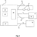
- the FIG. 4 shows in conjunction with FIG. 1
- the fire alarm and / or extinguishing control center has a control unit 24.
- the fire alarm and / or extinguishing control center at least one signal processing unit 25, in particular a microcontroller or a digital signal processor and preferably an operating and display unit 26.
- the memory of the fire alarm and / or extinguishing control center in which the discharge time t c , the control time t k and the monitoring time t b are stored.
- FIG. 1 shows the schematic representation of the system according to the invention for the deletion of objects and facilities with a first extinguishing agent supply device 17 a first extinguishing fluid, preferably a liquid synthetic extinguishing agent 14, in an extinguishing agent container 1, on which a valve 16 is arranged.
- the liquid synthetic extinguishing agent is superimposed with nitrogen.
- the nitrogen superposition pressure is 50 bar.
- the second arranged extinguishing agent supply device 18 comprises reservoir with a second extinguishing fluid, preferably a water reservoir 2 with water 3 or a water-based extinguishing agent and a conveyor 7, which generates the volume flow and pressure for the water or the water-based extinguishing agent.
- a second extinguishing fluid preferably a water reservoir 2 with water 3 or a water-based extinguishing agent and a conveyor 7, which generates the volume flow and pressure for the water or the water-based extinguishing agent.
- a first feed line 20 directs the liquid synthetic extinguishing agent 14 after opening the valve 16 by the fire alarm and / or extinguishing control center according to the invention to the separator 8 and a common pipe 9 and at least one nozzle 10.
- 3 nozzles are shown in the Schutzberiech 19 are located, in which the object to be protected, the object to be deleted 22 is applied in case of fire with extinguishing agent.
- the separator 8, the common pipe 9 and the nozzles 10 are formed to first guide the liquid synthetic extinguishing agent 14 and subsequently, if necessary, water 3 or water-based extinguishing agent to the object to be extinguished.
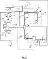
- FIG. 2 shows a variant of the system in which instead of the water storage tank 2, a water supply device 15 is arranged, preferably the public water supply, all other components and arrangements of this embodiment are identical to the in Fig. 1 illustrated plant.
- a water supply device 15 is arranged.
- the fire alarm and extinguishing control center 12 is designed and configured such that it controls the valve 16 and opens at the time t 1 when detecting a first fire signal, for discharging the first extinguishing fluid, preferably the liquid synthetic extinguishing agent 14, with the pressurized nitrogen from the extinguishing agent tank 1.
- the liquid synthetic extinguishing agent 14 passes through the common pipe 9 and the three nozzles 10 to the extinguishing object 20 in the protection area 19.
- the common pipe is designed and configured such that it controls the valve 16 and opens at the time t 1 when detecting a first fire signal, for discharging the first extinguishing fluid, preferably the liquid synthetic extinguishing agent 14, with the pressurized nitrogen from the extinguishing agent tank 1.
- the liquid synthetic extinguishing agent 14 passes through the common pipe 9 and the three nozzles 10 to the extinguishing object 20 in the protection area 19.
- the common pipe is designed and configured such that it controls the valve 16 and opens at the time
- Distribution pipe network 23 which directs the extinguishing agent to the nozzles 10, which are arranged around the protective object 22 in predefined positions.
- the predefined positions are determined so that the fire can be extinguished in a very short time with a minimum amount of extinguishing agent.
- the fire alarm and / or extinguishing control center 12 controls the fire alarm and / or extinguishing control center 12 additionally to the conveyor 7, which the second extinguishing fluid, preferably the water 3 or the water-based extinguishing agent, I from the reservoir 2 for the embodiment of Fig. 1 or discharges water from the water supply device 15 via the common pipe 9 and the nozzles 10 for deletion of the object 22 in the protection area 19.
- the second extinguishing fluid preferably the water 3 or the water-based extinguishing agent
- a pressure monitoring device 4 is arranged on or in the extinguishing agent container 1.
- the necessary pressure and the volume flow for application are achieved by the conveyor 7.
- the level monitoring device 5 and pressure monitoring device 4 are signal-conducting, in the illustrated example via the signal-conducting connection 13, preferably designed as an electrical line, connected to the fire alarm and / or control center 12. Pressure and level are detected and monitored by the fire alarm and / or extinguishing control center 12. If predetermined limit values are undershot and / or exceeded, this is sent to a predetermined receiving and / or signaling device.
- the conveyor 7 generates the required for the discharge of the water 3 volume flow and pressure.
- the extinguishing agent container 1 with the liquid synthetic extinguishing agent 14 is connected to the separating device 8 via the first supply line 21 and the water-conveying device 7 or the water-based extinguishing agent is connected to the second supply line 22 to the separating device 8.
- the common pipe 9 directs the extinguishing agent to the nozzles 10 in the protection area 19.
- the separator 8 ensures that only one extinguishing agent is in the pipe 9 and the water 3 or the water-based extinguishing agent and the liquid synthetic extinguishing agent 14th kept separate.
- Fig. 1 shows that in front of the extinguishing agent supply means 17 and 18, that is downstream of the extinguishing agent supply devices 17, 18 backflow preventer 6 are arranged. They prevent ingress of water 3 or water-based extinguishing agent into the first extinguishing agent supply device 17 and a penetration of the liquid synthetic extinguishing agent 14 in the second extinguishing agent supply means 18. There is a respective backflow preventer 6 between the extinguishing agent container 1 and the separation device 8 and between the conveyor 7 and the Separating device 8 is arranged.
- the pipe 9 leads to the nozzles 10, which apply the liquid synthetic extinguishing agent 14 and, if necessary, the water 3 to the protected object to be deleted 20.
- the conveyor 7, the valve 16 on the extinguishing agent tank 1, and the separator 8 are connected to their control with the fire alarm and / or extinguishing control center 12 signal-conducting.
- this signaling connection 13 is realized via electrical lines that are monitored by the fire alarm and / or extinguishing control center 12 for wire breakage and / or short circuit to detect malfunction immediately and report. Not shown is the wireless execution version of the signal-conducting connection thirteenth
- the first and second extinguishing agent supply means 17, 18 are driven, ie the valve 16 is driven at a first fire signal, it opens the extinguishing agent tank 1 and at a second fire signal in the predetermined monitoring period t b , the conveyor 7 is driven.
- the respective extinguishing agent is discharged via the common pipe 9 and the nozzles 10 and the fire is fought on or in the object to be deleted 22.
- fire alarm and / or extinguishing control center 12 is designed and arranged so that it controls the separation device 8 in the event of detection of a second fire signal at time t 2 before driving the second extinguishing agent supply means 18, for generating a switching position of the separation device 8, which the transport path of the second quenching fluid, preferably of the water 3 or of the water-based quenching agent, in the direction of the common pipeline 9 and the nozzles 10 releases and the transport path of the first quenching fluid, preferably the liquid synthetic extinguishing agent 14, from the first extinguishing agent supply means 17 in the direction of the common pipe 9 and the nozzles 10 completely blocked.
- the transport path of the second quenching fluid preferably of the water 3 or of the water-based quenching agent
- This switching position of the separator is the secondary switching position of the separator 8, since the second stage of deletion with the second extinguishing fluid, preferably with water 3 or water-based extinguishing agent only in case of need, if the first stage of deletion with the first extinguishing fluid, preferably with the liquid synthetic extinguishing agent 14, has not led to the deletion and a second fire signal has been detected.
- the fire alarm and / or extinguishing control center 12 is further configured and arranged to perform a control of the separation device 8 to generate a switching position of the separation device 8, which the transport path of the first extinguishing fluid, preferably the liquid synthetic extinguishing agent 14 prior to the activation of the first extinguishing agent supply means 17 , in the direction of the common pipe 9 and the at least one nozzle 10 releases and completely blocks the transport path of the second extinguishing fluid, preferably the water 3 or the water-based extinguishing agent from the second extinguishing agent supply device 18 in the direction of the common pipe 9 and the at least one nozzle 10.
- This switching position of the separating device is the primary switching position of the separating device 8, since the first stage of the deletion with the first quenching fluid, preferably the liquid synthetic extinguishing agent 14, takes place.
- This activation of the separating device 8 can be omitted if it is already in this primary switching position before the activation of the first extinguishing agent supply device 17.
- the remaining nitrogen flows and removes all residues of the synthetic extinguishing agent 14 from the pipeline 9.
- a rinsing of the common pipe 9 and the at least one nozzle 10 with a gas in this embodiment with nitrogen.
- Fig. 3 schematically shows the timing of the method steps of a particularly preferred embodiment of the method according to the invention using two different liquid extinguishing agents 3, 14, which are provided by two separate extinguishing agent supply means 17, 18 via a separator 8 and a common pipe 9 and at least one nozzle 10, shown.
- the second extinguishing agent supply means 18 in one Reservoir the second extinguishing fluid, preferably in a water reservoir 2 or from a water supply device 15 water 3 or water-based extinguishing agent ready.
- a first fire signal is detected by at least one event detector 11 and a fire alarm and / or extinguishing control center 12.
- the activation of the second extinguishing agent supply device 18 and the second extinguishing fluid, preferably the water 3 or the water-based extinguishing agent is via the separator 8, the common pipe 9 and the at least one nozzle 10 for deletion discharged.
- the control of the second extinguishing agent supply device 18 takes place in this case only if the time t 2 after complete or partial emptying of the extinguishing medium container 1, after expiry of the discharge time t c is, however, within a monitoring period t b, wherein the monitoring period of time t b from the time t 1 starting from the sum of the emptying time t c and a control time t k , wherein the control time t k is following the emptying time t c and in this time t k the fire alarm and / or extinguishing control center (12) checks whether a fire signal is detected and the time t 2 satisfies the inequality (t 1 + t c ) ⁇ t 2 ⁇ (t 1 + t b ).
Claims (17)
- Poste de commande d'alarme incendie et/ou d'extinction pour la commande de deux dispositifs d'alimentation en agents d'extinction avec une unité de commande (24), dans lequel l'unité de commande (24) est conçue de façon à déclencher un premier dispositif d'alimentation en agents d'extinction (17) lors de la détection d'un premier signal de feu à l'instant t1, caractérisé en ce que l'unité de commande (24) est en outre conçue de façon à déclencher un deuxième dispositif d'alimentation en agents d'extinction (18) lors de la détection d'un deuxième signal de feu à l'instant t2, lorsqu'elle a vérifié si l'instant t2 remplit l'inégalité (t1+tc) < t2 <(t1+tb), dans laquelle tc représente un temps de vidange pour la vidange complète ou partielle d'au moins un réservoir d'agent d'extinction (1) du premier dispositif d'alimentation en agents d'extinction (17), tk représente un temps de contrôle à la suite du temps de vidange tc et tb représente une durée de surveillance et la durée de surveillance tb est, à partir de l'instant t1, la somme du temps de vidange tc et du temps de contrôle tk.
- Poste de commande d'alarme incendie et/ou d'extinction selon la revendication 1, dans lequel la programmation mémorisée dans une unité de traitement de signaux (25) de l'unité de commande présente un module de vérification, qui génère un signal pour déclencher le deuxième dispositif d'alimentation en agents d'extinction lors de la détection du deuxième signal de feu à l'instant t2, lorsque le module de vérification constate que l'instant t2 remplit l'inégalité (t1+tc) < t2 < (t1+tb).
- Poste de commande d'alarme incendie et/ou d'extinction selon une des revendications 1 ou 2, dans lequel le poste de commande d'alarme incendie et/ou d'extinction présente une mémoire et comprend en outre une interface de programmation, qui est configurée et conçue de telle manière que le temps de vidange tc, le temps de contrôle tk et la durée de surveillance tb soient stockés dans la mémoire par l'intermédiaire de l'interface de programmation avec un moyen de programmation et/ou de configuration.
- Poste de commande d'alarme incendie et/ou d'extinction selon la revendication 3, dans lequel les moyens de programmation et/ou de configuration représentent un ordinateur personnel, une tablette tactile, un ordinateur portable, un smartphone ou un outil de service ou de programmation.
- Poste de commande d'alarme incendie et/ou d'extinction selon une des revendications 1 à 4, dans lequel il présente en outre une unité d'affichage et de commande (26) et il est conçu de telle manière que les paramètres temps de vidange tc, temps de contrôle tk et durée de surveillance tb puissent être introduits et/ou modifiés en outre ou exclusivement par des éléments de commande de l'unité d'affichage et de commande.
- Poste de commande d'alarme incendie et/ou d'extinction selon une des revendications 1 à 5, dans lequel le poste de commande d'alarme incendie et/ou d'extinction est en outre configuré et conçu de telle manière qu'avant le déclenchement du premier dispositif d'alimentation en agents d'extinction (17) il opère une commande d'un dispositif de séparation (8), pour la production d'une position de commutation primaire du dispositif de séparation (8), qui libère le chemin de transport d'un premier fluide d'extinction, de préférence un agent d'extinction synthétique liquide (14), en direction d'une conduite commune (9) et d'au moins une buse (10) et qui bloque entièrement le chemin de transport d'un deuxième fluide d'extinction, de préférence de l'eau (3) ou un agent d'extinction aqueux, du deuxième dispositif d'alimentation en agents d'extinction (18) en direction de la conduite commune (9) et de ladite au moins une buse (10).
- Poste de commande d'alarme incendie et/ou d'extinction selon une des revendications 1 à 6, dans lequel le poste de commande d'alarme incendie et/ou d'extinction est configuré et conçu de telle manière qu'en cas de détection du deuxième signal de feu à l'instant t2 il commande avant le déclenchement du deuxième dispositif d'alimentation en agents d'extinction (18) le dispositif de séparation (8), pour produire une position de commutation secondaire du dispositif de séparation (8), qui libère le chemin de transport du deuxième fluide d'extinction, de préférence de l'eau (3) ou de l'agent d'extinction aqueux, en direction de la conduite commune (9) et des buses (10) et qui bloque entièrement le chemin de transport du premier fluide d'extinction, de préférence de l'agent d'extinction synthétique liquide (14), du premier dispositif d'alimentation en agents d'extinction (17) en direction de la conduite commune (9) et des buses (10).
- Poste de commande d'alarme incendie et/ou d'extinction selon une des revendications 1 à 7, dans lequel il est en outre conçu de façon à couper à l'instant t1 ou après une durée de retard prédéterminée ta à la suite de celui-ci l'alimentation électrique de la machine, de l'installation ou de l'équipement à éteindre.
- Poste de commande d'alarme incendie et/ou d'extinction selon une des revendications précédentes, dans lequel il est conçu de façon à retransmettre tous les états de commutation et de fonctionnement à des dispositifs de réception prédéfinis, en particulier à des systèmes de gestion de bâtiment.
- Poste de commande d'alarme incendie et/ou d'extinction selon une des revendications 1 à 9, dans lequel il présente, pour la détection de paramètres du fluide d'extinction du premier dispositif d'alimentation en agents d'extinction (17), une liaison de transmission de signaux vers des moyens de détection de paramètres du fluide d'extinction (28) et il est en outre conçu pour calculer le temps de vidange tc à un instant tm > t1 sur la base des paramètres du fluide d'extinction.
- Poste de commande d'alarme incendie et/ou d'extinction selon la revendication 10, dans lequel on détecte les paramètres du fluide d'extinction:• pression et/ou température dans le réservoir d'agent d'extinction,• débit du fluide d'extinction en liaison avec la durée détectée de sortie du fluide d'extinction à partir de l'instant t1, ou• différence de masse du fluide d'extinction avant ou à l'instant t1 et à l'instant tm,ou une combinaison de ceux-ci.
- Procédé de commande de deux dispositifs d'alimentation en agents d'extinction au moyen d'un poste de commande d'alarme incendie et/ou d'extinction, dans lequel on déclenche un premier dispositif d'alimentation en agents d'extinction (17) après détection d'un premier signal de feu à l'instant t1, caractérisé en ce que le procédé comprend en outre les étapes de procédé suivantes exécutées de préférence l'une après l'autre:• détection d'un deuxième signal de feu à l'instant t2,• déclenchement d'un deuxième dispositif d'alimentation en agents d'extinction (18), après vérification par le poste de commande d'alarme incendie et/ou d'extinction, que l'instant t2 remplit l'inégalité (t1+tc) < t2 < (t1+tb),dans lequel tc représente un temps de vidange pour la vidange complète ou partielle d'au moins un réservoir d'agent d'extinction (1) du premier dispositif d'alimentation en agents d'extinction (17), tk représente un temps de contrôle à la suite du temps de vidange tc et tb représente une durée de surveillance et la durée de surveillance tb est, à partir de l'instant t1, la somme du temps de vidange tc et du temps de contrôle tk.
- Procédé selon la revendication 12, caractérisé en ce que le temps de vidange tc est prédéterminé en tant que paramètre mémorisé dans le poste de commande d'alarme incendie et/ou d'extinction ou on le calcule à l'instant tm > t1.
- Procédé selon la revendication 13, caractérisé en ce que l'on effectue le calcul du temps de vidange tc sur la base de paramètres du fluide d'extinction du premier dispositif d'alimentation en agents d'extinction détectés avec des moyens de détection de paramètres du fluide d'extinction (28).
- Procédé selon la revendication 14, caractérisé en outre par les étapes de procédé suivantes:détection des paramètres du fluide d'extinction au moyen d'une liaison de transmission de signaux des moyens de détection de paramètres du fluide d'extinction avec le poste de commande d'alarme incendie et/ou d'extinction, etmémorisation des paramètres du fluide d'extinction dans le poste de commande d'alarme incendie et/ou d'extinction.
- Procédé selon la revendication 15, caractérisé en ce que les paramètres du fluide d'extinction représentent:• la pression et/ou la température dans le réservoir de fluide d'extinction,• le débit du fluide d'extinction en liaison avec la durée détectée de la sortie du fluide d'extinction à partir de l'instant t1, ou• la différence de masse du fluide d'extinction avant ou à l'instant t1 et à l'instant tm,ou une combinaison de ceux.ci.
- Procédé selon une des revendications 12 à 16, caractérisé en ce que l'on opère avant le déclenchement du premier dispositif d'alimentation en agents d'extinction (17) une commande d'un dispositif de séparation (8), pour la production d'une position de commutation primaire du dispositif de séparation (8), qui libère le chemin de transport du premier fluide d'extinction, de préférence un agent d'extinction synthétique liquide, en direction d'une conduite commune (9) et d'au moins une buse (10) et qui bloque entièrement le chemin de transport du deuxième fluide d'extinction, de préférence de l'eau (3) ou un agent d'extinction aqueux, du deuxième dispositif d'alimentation en agents d'extinction (18) en direction de la conduite commune (9) et de ladite au moins une buse (10).
Priority Applications (1)
| Application Number | Priority Date | Filing Date | Title |
|---|---|---|---|
| EP15700139.7A EP3094385B1 (fr) | 2014-01-17 | 2015-01-12 | Poste de commande et procédé pour actionner deux dispositifs d'alimentation en agents extincteurs |
Applications Claiming Priority (3)
| Application Number | Priority Date | Filing Date | Title |
|---|---|---|---|
| EP14151689.8A EP2896432B1 (fr) | 2014-01-17 | 2014-01-17 | Procédé et installation d'extinction à l'aide d'un fluide d'extinction synthétique liquide |
| PCT/EP2015/050386 WO2015107013A1 (fr) | 2014-01-17 | 2015-01-12 | Poste de commande et procédé pour actionner deux dispositifs d'alimentation en agents extincteurs |
| EP15700139.7A EP3094385B1 (fr) | 2014-01-17 | 2015-01-12 | Poste de commande et procédé pour actionner deux dispositifs d'alimentation en agents extincteurs |
Publications (2)
| Publication Number | Publication Date |
|---|---|
| EP3094385A1 EP3094385A1 (fr) | 2016-11-23 |
| EP3094385B1 true EP3094385B1 (fr) | 2018-05-16 |
Family
ID=49949581
Family Applications (2)
| Application Number | Title | Priority Date | Filing Date |
|---|---|---|---|
| EP14151689.8A Active EP2896432B1 (fr) | 2014-01-17 | 2014-01-17 | Procédé et installation d'extinction à l'aide d'un fluide d'extinction synthétique liquide |
| EP15700139.7A Active EP3094385B1 (fr) | 2014-01-17 | 2015-01-12 | Poste de commande et procédé pour actionner deux dispositifs d'alimentation en agents extincteurs |
Family Applications Before (1)
| Application Number | Title | Priority Date | Filing Date |
|---|---|---|---|
| EP14151689.8A Active EP2896432B1 (fr) | 2014-01-17 | 2014-01-17 | Procédé et installation d'extinction à l'aide d'un fluide d'extinction synthétique liquide |
Country Status (7)
| Country | Link |
|---|---|
| US (3) | US10363445B2 (fr) |
| EP (2) | EP2896432B1 (fr) |
| CN (2) | CN106061560B (fr) |
| ES (2) | ES2588103T3 (fr) |
| MY (1) | MY178968A (fr) |
| PL (1) | PL2896432T3 (fr) |
| WO (2) | WO2015107007A1 (fr) |
Families Citing this family (19)
| Publication number | Priority date | Publication date | Assignee | Title |
|---|---|---|---|---|
| ES2588103T3 (es) * | 2014-01-17 | 2016-10-28 | Minimax Gmbh & Co Kg | Procedimiento e instalación para la extinción con un agente extintor sintético líquido y agua |
| CN106327773A (zh) * | 2015-07-01 | 2017-01-11 | 西门子瑞士有限公司 | 火灾报警控制器的配置装置及其配置方法 |
| EP3558472B1 (fr) * | 2016-12-20 | 2024-01-24 | Carrier Corporation | Système et procédé de protection contre l'incendie pour enceinte |
| AT520060B1 (de) * | 2017-05-31 | 2019-02-15 | Thurnher Julius | Vorrichtung zur Zuführung von Löschmittel |
| US11013942B2 (en) * | 2017-09-26 | 2021-05-25 | The Reliable Automatic Sprinkler Co. Inc. | Pressure maintenance device with automatic switchover for use in a fire protection sprinkler system, and a related method |
| US20190168047A1 (en) * | 2017-12-02 | 2019-06-06 | M-Fire Suppression, Inc. | Method of and system for suppressing fire using anenvironmentally-clean free-radical chemical-reaction interrupting water mist so as to reduce water damage and smoke production and the risk of fire re-ignition |
| US11241599B2 (en) * | 2018-05-09 | 2022-02-08 | William A. Enk | Fire suppression system |
| CN108776448A (zh) * | 2018-06-26 | 2018-11-09 | 无锡南理工科技发展有限公司 | 多重防护的物联网计算机用远程监控装置 |
| DE102018118970A1 (de) * | 2018-08-03 | 2020-02-06 | Minimax Viking Research & Development Gmbh | Verfahren zur Bekämpfung eines Brandereignisses und System zur Durchführung des Verfahrens |
| CN112334198B (zh) * | 2018-11-30 | 2022-11-08 | 开利公司 | 灭火系统远程监测 |
| EP3892018A1 (fr) * | 2018-12-06 | 2021-10-13 | Carrier Corporation | Détecteurs de danger en réseau qui surveillent le niveau de préparation et la disponibilité |
| CN109513138A (zh) * | 2018-12-26 | 2019-03-26 | 吉林省福瑞达水电设备工程有限公司 | 一种电力设备自动灭火装置 |
| DE102019123788B3 (de) * | 2019-09-05 | 2020-12-17 | Fogtec Brandschutz Gmbh | Brandbekämpfungssystem, Schienenfahrzeug mit Brandbekämpfungssystem sowie Verfahren zum Betreiben eines Brandbekämpfungssystems |
| CN110575631A (zh) * | 2019-09-27 | 2019-12-17 | 芜湖中集瑞江汽车有限公司 | 一种罐箱消防安全装置 |
| CN110743116A (zh) * | 2019-10-08 | 2020-02-04 | 湖北及安盾消防科技有限公司 | 一种可延时喷放和持续灭火的装置及灭火方法 |
| KR102243460B1 (ko) * | 2020-06-03 | 2021-04-21 | 이영숙 | 화재 진압 시스템 |
| CN116096465A (zh) * | 2020-12-25 | 2023-05-09 | 宁德时代新能源科技股份有限公司 | 一种消防开关设备以及消防系统 |
| WO2022269405A1 (fr) * | 2021-06-22 | 2022-12-29 | Azari Hossein | Système d'extinction d'incendie |
| CN115944878A (zh) * | 2022-12-23 | 2023-04-11 | 上海纳米技术及应用国家工程研究中心有限公司 | 一种车载水成膜灭火剂寿命估计装置 |
Family Cites Families (44)
| Publication number | Priority date | Publication date | Assignee | Title |
|---|---|---|---|---|
| US2292794A (en) * | 1938-07-05 | 1942-08-11 | Raymond P Paradise | Method of fire extinguishing |
| FI98495C (sv) * | 1996-03-11 | 1997-07-10 | Goeran Sundholm | Brandsläckningssystem |
| DE19625559C1 (de) * | 1996-06-26 | 1997-10-09 | Daimler Benz Aerospace Ag | Verfahren zur Brandbekämpfung und Vorrichtung zu seiner Durchführung |
| FI102041B1 (fi) * | 1996-09-05 | 1998-10-15 | Goeran Sundholm | Laitteisto palon torjumiseksi |
| DE19700578A1 (de) * | 1997-01-10 | 1998-07-16 | Viktor Gossen | Stationäre Vorrichtungen für automatische Brandbekämpfung mit Dampf |
| US5947207A (en) * | 1997-03-31 | 1999-09-07 | Pittway Corporation | Dual sprinkler system |
| US6390203B1 (en) * | 1999-01-11 | 2002-05-21 | Yulian Y. Borisov | Fire suppression apparatus and method |
| DE10204384C1 (de) * | 2002-02-04 | 2003-07-17 | Preussag Ag Minimax | Verfahren zur Steuerung von stationären Löschanlagen |
| GB2386835B (en) * | 2002-03-28 | 2005-04-27 | Kidde Plc | Fire and explosion suppression |
| KR20040096713A (ko) * | 2003-05-10 | 2004-11-17 | 한국전력기술 주식회사 | 공통배관을 이용한 가스계 겸용 물분무 소화설비시스템 |
| CN1805917A (zh) * | 2003-06-18 | 2006-07-19 | 纳幕尔杜邦公司 | 氟酮化合物 |
| DE10361020B4 (de) * | 2003-12-24 | 2010-09-30 | Airbus Deutschland Gmbh | Feuerlöscheinrichtung |
| US7775292B1 (en) * | 2004-07-26 | 2010-08-17 | Romanco Ernest K | CO2 fire suppression monitoring apparatus and method |
| US20060032939A1 (en) * | 2004-08-10 | 2006-02-16 | Crash Rescue Equipment Service, Inc. | Fire retardant management system |
| US20060113403A1 (en) * | 2004-12-01 | 2006-06-01 | Firebreak Spray Systems, Llc | Fire retardant distribution system for wildfire protection |
| US7810577B2 (en) * | 2005-08-30 | 2010-10-12 | Federal Express Corporation | Fire sensor, fire detection system, fire suppression system, and combinations thereof |
| NL1030627C2 (nl) * | 2005-12-08 | 2007-06-11 | Antonius Theodorus Ceci Hauzer | Brandblussysteem in een luchtfiltersysteem en een werkwijze daarvoor. |
| DE102006032503A1 (de) * | 2006-07-12 | 2008-01-17 | Fogtec Brandschutz Gmbh & Co. Kg | Verfahren und Vorrichtung zur Brandbekämpfung |
| DE102006048015B4 (de) * | 2006-10-09 | 2015-01-29 | Minimax Gmbh & Co. Kg | Feuerlöschanlage für ein Gehäuse |
| CN102015033A (zh) * | 2007-09-24 | 2011-04-13 | Utc消防及保安公司 | 水增强的惰性气体淹没灭火 |
| US20090194299A1 (en) * | 2008-02-05 | 2009-08-06 | Neumann Mark C | Flexible Hose Supply Line For Appliance Fire Suppression System |
| DK2186546T3 (da) * | 2008-10-07 | 2011-01-03 | Amrona Ag | Inertgasbrandslukningsanlæg til formindskelse af risikoen og til slukning af brande i et beskyttelsesrum |
| CN201279361Y (zh) * | 2008-10-23 | 2009-07-29 | 明光市浩淼消防科技发展有限公司 | 三相射流喷射灭火装置 |
| WO2010069353A1 (fr) * | 2008-12-19 | 2010-06-24 | Minimax Gmbh & Co. Kg | Procédé et dispositif de détection anticipée d'incendies |
| US9033061B2 (en) * | 2009-03-23 | 2015-05-19 | Kidde Technologies, Inc. | Fire suppression system and method |
| US20110056707A1 (en) * | 2009-09-08 | 2011-03-10 | Jonathan Gamble | Fire-Extinguishing System and Method for Operating Servo Motor-Driven Foam Pump |
| CN201519406U (zh) * | 2009-10-15 | 2010-07-07 | 江苏卡威专用汽车制造有限公司 | 举高式复合射流灭火装置 |
| CN201591928U (zh) * | 2009-10-15 | 2010-09-29 | 江苏卡威专用汽车制造有限公司 | 管套管式复合射流消防炮 |
| DE102009046148A1 (de) | 2009-10-29 | 2011-05-05 | Robert Bosch Gmbh | Ultraschallwandler zum Einsatz in einem fluiden Medium |
| US8505642B2 (en) * | 2009-11-05 | 2013-08-13 | Firetrace Usa, Llc | Methods and apparatus for dual stage hazard control system |
| GB2477718A (en) * | 2010-02-04 | 2011-08-17 | Graviner Ltd Kidde | Inert gas suppression system for temperature control |
| JP5516000B2 (ja) * | 2010-04-14 | 2014-06-11 | 株式会社Ihi | 貯留石炭自然発火監視制御装置 |
| WO2012021552A2 (fr) * | 2010-08-10 | 2012-02-16 | Tyco Fire Products Lp | Système et procédé d'extinction automatique d'incendie à fort débit |
| EP2469492B1 (fr) * | 2010-11-29 | 2013-05-29 | Minimax GmbH & Co. KG | Procédé et dispositif destinés à la détection d'incendie dans des volumes |
| US8973670B2 (en) * | 2010-12-30 | 2015-03-10 | William Armand Enk, SR. | Fire suppression system |
| US8863856B2 (en) * | 2011-02-09 | 2014-10-21 | Firetrace Usa, Llc | Methods and apparatus for multi-stage fire suppression |
| US8925642B2 (en) * | 2011-06-29 | 2015-01-06 | The Boeing Company | Scalable cargo fire-suppression agent distribution system |
| US8967284B2 (en) * | 2011-10-06 | 2015-03-03 | Alliant Techsystems Inc. | Liquid-augmented, generated-gas fire suppression systems and related methods |
| EP2594319B1 (fr) | 2011-11-18 | 2018-05-30 | Minimax GmbH & Co KG | Installation d'extinction ou d'intertisation à l'aide d'un agent d'extinction liquide synthétique |
| CN202961631U (zh) * | 2012-11-22 | 2013-06-05 | 陕西银河消防科技装备有限公司 | 一种移动式多种灭火剂消防装置 |
| US9526931B2 (en) * | 2012-12-07 | 2016-12-27 | The Boeing Company | Cargo fire-suppression agent distribution system |
| US9446269B2 (en) * | 2012-12-17 | 2016-09-20 | General Electric Company | System and method for fire suppression |
| CN103223216B (zh) * | 2013-04-18 | 2016-03-30 | 陕西银河消防科技装备有限公司 | 一种多用途公路灭火救援装置 |
| ES2588103T3 (es) * | 2014-01-17 | 2016-10-28 | Minimax Gmbh & Co Kg | Procedimiento e instalación para la extinción con un agente extintor sintético líquido y agua |
-
2014
- 2014-01-17 ES ES14151689.8T patent/ES2588103T3/es active Active
- 2014-01-17 EP EP14151689.8A patent/EP2896432B1/fr active Active
- 2014-01-17 PL PL14151689.8T patent/PL2896432T3/pl unknown
-
2015
- 2015-01-09 MY MYPI2016001315A patent/MY178968A/en unknown
- 2015-01-09 US US15/111,948 patent/US10363445B2/en active Active
- 2015-01-09 CN CN201580011093.0A patent/CN106061560B/zh active Active
- 2015-01-09 WO PCT/EP2015/050328 patent/WO2015107007A1/fr active Application Filing
- 2015-01-12 CN CN201580011112.XA patent/CN106061561B/zh active Active
- 2015-01-12 ES ES15700139.7T patent/ES2684329T3/es active Active
- 2015-01-12 US US15/111,979 patent/US10363446B2/en active Active
- 2015-01-12 EP EP15700139.7A patent/EP3094385B1/fr active Active
- 2015-01-12 WO PCT/EP2015/050386 patent/WO2015107013A1/fr active Application Filing
-
2017
- 2017-12-21 US US15/849,768 patent/US10398915B2/en active Active
Non-Patent Citations (1)
| Title |
|---|
| None * |
Also Published As
| Publication number | Publication date |
|---|---|
| EP3094385A1 (fr) | 2016-11-23 |
| US20160332012A1 (en) | 2016-11-17 |
| WO2015107013A1 (fr) | 2015-07-23 |
| ES2588103T3 (es) | 2016-10-28 |
| CN106061561A (zh) | 2016-10-26 |
| ES2684329T3 (es) | 2018-10-02 |
| US20160346580A1 (en) | 2016-12-01 |
| CN106061560B (zh) | 2019-12-24 |
| CN106061561B (zh) | 2019-12-17 |
| EP2896432A1 (fr) | 2015-07-22 |
| CN106061560A (zh) | 2016-10-26 |
| EP2896432B1 (fr) | 2016-05-25 |
| US10398915B2 (en) | 2019-09-03 |
| MY178968A (en) | 2020-10-26 |
| PL2896432T3 (pl) | 2016-11-30 |
| US20180111014A1 (en) | 2018-04-26 |
| WO2015107007A1 (fr) | 2015-07-23 |
| US10363446B2 (en) | 2019-07-30 |
| US10363445B2 (en) | 2019-07-30 |
Similar Documents
| Publication | Publication Date | Title |
|---|---|---|
| EP3094385B1 (fr) | Poste de commande et procédé pour actionner deux dispositifs d'alimentation en agents extincteurs | |
| DE10361020B4 (de) | Feuerlöscheinrichtung | |
| EP2186546B1 (fr) | Installation de gaz inerte destinée à la réduction du risque et à l'extinction d'incendies dans un espace protégé | |
| EP2594319B1 (fr) | Installation d'extinction ou d'intertisation à l'aide d'un agent d'extinction liquide synthétique | |
| DE112010002647T5 (de) | Geldautomaten-Sicherheitssystem | |
| EP2399649B1 (fr) | Système anti-feu pour aéronef et procédé de lutte contre les incendies à bord d'un aéronef | |
| EP3829724A1 (fr) | Procédé de lutte contre un incendie et système de mise en oeuvre du procédé | |
| WO1998000201A1 (fr) | Procede et dispositif d'application dynamique d'un agent extincteur | |
| EP2322251B1 (fr) | Méthode pour l'opération d'un ensemble d'extinction d'incendie | |
| EP2998002B1 (fr) | Installation d'extinction à gaz inerte | |
| DE102005045647A1 (de) | Einbruch-Sprengschutz mit Täterabwehr für Wertbehältnisse und Automaten | |
| DE102009041578A1 (de) | Brandlöschsystem mit dem Löschmittel Inertgas | |
| DE102006051115A1 (de) | Sicherheitseinrichtung für Geldausgabeautomaten, Tresore oder dergleichen | |
| AT500813B1 (de) | Feuerlöschanlage für ein gasgemisch als löschmittel | |
| EP3578232B1 (fr) | Procédé d'extinction d'un front de flamme et dispositif d'extinction | |
| EP2422850B1 (fr) | Dispositif d'extinction d'incendies | |
| DD266275A1 (de) | Spruehwasseranlage und schaltungsanordnung zu deren steuerung | |
| DE202014103162U1 (de) | System zum Sichern von Behältnissen zur Aufbewahrung von Wertsachen | |
| EP2916298A1 (fr) | Système de fixation de récipients destinés au stockage d'objets de valeur | |
| DE102014013269A1 (de) | Brandpräventionsvorrichtung für ein Fahrzeug | |
| DE102009052852A1 (de) | Brandlöschsystem mit dem Löschmittel Inertgas | |
| DE102012021651A1 (de) | Technisches Lagersystem mit integriertem Brandschutz | |
| EP2446933A2 (fr) | Procédé d'extinction d'incendies sur des bâtiments et installations |
Legal Events
| Date | Code | Title | Description |
|---|---|---|---|
| PUAI | Public reference made under article 153(3) epc to a published international application that has entered the european phase |
Free format text: ORIGINAL CODE: 0009012 |
|
| 17P | Request for examination filed |
Effective date: 20160711 |
|
| AK | Designated contracting states |
Kind code of ref document: A1 Designated state(s): AL AT BE BG CH CY CZ DE DK EE ES FI FR GB GR HR HU IE IS IT LI LT LU LV MC MK MT NL NO PL PT RO RS SE SI SK SM TR |
|
| AX | Request for extension of the european patent |
Extension state: BA ME |
|
| DAX | Request for extension of the european patent (deleted) | ||
| RIC1 | Information provided on ipc code assigned before grant |
Ipc: G08B 17/00 20060101ALI20170809BHEP Ipc: A62C 99/00 20100101ALI20170809BHEP Ipc: A62C 35/13 20060101AFI20170809BHEP Ipc: A62C 37/44 20060101ALI20170809BHEP |
|
| GRAP | Despatch of communication of intention to grant a patent |
Free format text: ORIGINAL CODE: EPIDOSNIGR1 |
|
| STAA | Information on the status of an ep patent application or granted ep patent |
Free format text: STATUS: GRANT OF PATENT IS INTENDED |
|
| INTG | Intention to grant announced |
Effective date: 20180103 |
|
| GRAS | Grant fee paid |
Free format text: ORIGINAL CODE: EPIDOSNIGR3 |
|
| GRAA | (expected) grant |
Free format text: ORIGINAL CODE: 0009210 |
|
| STAA | Information on the status of an ep patent application or granted ep patent |
Free format text: STATUS: THE PATENT HAS BEEN GRANTED |
|
| AK | Designated contracting states |
Kind code of ref document: B1 Designated state(s): AL AT BE BG CH CY CZ DE DK EE ES FI FR GB GR HR HU IE IS IT LI LT LU LV MC MK MT NL NO PL PT RO RS SE SI SK SM TR |
|
| REG | Reference to a national code |
Ref country code: GB Ref legal event code: FG4D Free format text: NOT ENGLISH |
|
| REG | Reference to a national code |
Ref country code: CH Ref legal event code: EP |
|
| REG | Reference to a national code |
Ref country code: IE Ref legal event code: FG4D Free format text: LANGUAGE OF EP DOCUMENT: GERMAN |
|
| REG | Reference to a national code |
Ref country code: DE Ref legal event code: R096 Ref document number: 502015004271 Country of ref document: DE |
|
| REG | Reference to a national code |
Ref country code: AT Ref legal event code: REF Ref document number: 999006 Country of ref document: AT Kind code of ref document: T Effective date: 20180615 |
|
| REG | Reference to a national code |
Ref country code: NL Ref legal event code: MP Effective date: 20180516 |
|
| REG | Reference to a national code |
Ref country code: ES Ref legal event code: FG2A Ref document number: 2684329 Country of ref document: ES Kind code of ref document: T3 Effective date: 20181002 |
|
| REG | Reference to a national code |
Ref country code: LT Ref legal event code: MG4D |
|
| PG25 | Lapsed in a contracting state [announced via postgrant information from national office to epo] |
Ref country code: LT Free format text: LAPSE BECAUSE OF FAILURE TO SUBMIT A TRANSLATION OF THE DESCRIPTION OR TO PAY THE FEE WITHIN THE PRESCRIBED TIME-LIMIT Effective date: 20180516 Ref country code: SE Free format text: LAPSE BECAUSE OF FAILURE TO SUBMIT A TRANSLATION OF THE DESCRIPTION OR TO PAY THE FEE WITHIN THE PRESCRIBED TIME-LIMIT Effective date: 20180516 Ref country code: BG Free format text: LAPSE BECAUSE OF FAILURE TO SUBMIT A TRANSLATION OF THE DESCRIPTION OR TO PAY THE FEE WITHIN THE PRESCRIBED TIME-LIMIT Effective date: 20180816 Ref country code: NO Free format text: LAPSE BECAUSE OF FAILURE TO SUBMIT A TRANSLATION OF THE DESCRIPTION OR TO PAY THE FEE WITHIN THE PRESCRIBED TIME-LIMIT Effective date: 20180816 Ref country code: FI Free format text: LAPSE BECAUSE OF FAILURE TO SUBMIT A TRANSLATION OF THE DESCRIPTION OR TO PAY THE FEE WITHIN THE PRESCRIBED TIME-LIMIT Effective date: 20180516 |
|
| PG25 | Lapsed in a contracting state [announced via postgrant information from national office to epo] |
Ref country code: HR Free format text: LAPSE BECAUSE OF FAILURE TO SUBMIT A TRANSLATION OF THE DESCRIPTION OR TO PAY THE FEE WITHIN THE PRESCRIBED TIME-LIMIT Effective date: 20180516 Ref country code: GR Free format text: LAPSE BECAUSE OF FAILURE TO SUBMIT A TRANSLATION OF THE DESCRIPTION OR TO PAY THE FEE WITHIN THE PRESCRIBED TIME-LIMIT Effective date: 20180817 Ref country code: LV Free format text: LAPSE BECAUSE OF FAILURE TO SUBMIT A TRANSLATION OF THE DESCRIPTION OR TO PAY THE FEE WITHIN THE PRESCRIBED TIME-LIMIT Effective date: 20180516 Ref country code: RS Free format text: LAPSE BECAUSE OF FAILURE TO SUBMIT A TRANSLATION OF THE DESCRIPTION OR TO PAY THE FEE WITHIN THE PRESCRIBED TIME-LIMIT Effective date: 20180516 Ref country code: NL Free format text: LAPSE BECAUSE OF FAILURE TO SUBMIT A TRANSLATION OF THE DESCRIPTION OR TO PAY THE FEE WITHIN THE PRESCRIBED TIME-LIMIT Effective date: 20180516 |
|
| PG25 | Lapsed in a contracting state [announced via postgrant information from national office to epo] |
Ref country code: RO Free format text: LAPSE BECAUSE OF FAILURE TO SUBMIT A TRANSLATION OF THE DESCRIPTION OR TO PAY THE FEE WITHIN THE PRESCRIBED TIME-LIMIT Effective date: 20180516 Ref country code: SK Free format text: LAPSE BECAUSE OF FAILURE TO SUBMIT A TRANSLATION OF THE DESCRIPTION OR TO PAY THE FEE WITHIN THE PRESCRIBED TIME-LIMIT Effective date: 20180516 Ref country code: CZ Free format text: LAPSE BECAUSE OF FAILURE TO SUBMIT A TRANSLATION OF THE DESCRIPTION OR TO PAY THE FEE WITHIN THE PRESCRIBED TIME-LIMIT Effective date: 20180516 Ref country code: PL Free format text: LAPSE BECAUSE OF FAILURE TO SUBMIT A TRANSLATION OF THE DESCRIPTION OR TO PAY THE FEE WITHIN THE PRESCRIBED TIME-LIMIT Effective date: 20180516 Ref country code: DK Free format text: LAPSE BECAUSE OF FAILURE TO SUBMIT A TRANSLATION OF THE DESCRIPTION OR TO PAY THE FEE WITHIN THE PRESCRIBED TIME-LIMIT Effective date: 20180516 Ref country code: EE Free format text: LAPSE BECAUSE OF FAILURE TO SUBMIT A TRANSLATION OF THE DESCRIPTION OR TO PAY THE FEE WITHIN THE PRESCRIBED TIME-LIMIT Effective date: 20180516 |
|
| REG | Reference to a national code |
Ref country code: DE Ref legal event code: R097 Ref document number: 502015004271 Country of ref document: DE |
|
| PG25 | Lapsed in a contracting state [announced via postgrant information from national office to epo] |
Ref country code: SM Free format text: LAPSE BECAUSE OF FAILURE TO SUBMIT A TRANSLATION OF THE DESCRIPTION OR TO PAY THE FEE WITHIN THE PRESCRIBED TIME-LIMIT Effective date: 20180516 |
|
| PLBE | No opposition filed within time limit |
Free format text: ORIGINAL CODE: 0009261 |
|
| STAA | Information on the status of an ep patent application or granted ep patent |
Free format text: STATUS: NO OPPOSITION FILED WITHIN TIME LIMIT |
|
| 26N | No opposition filed |
Effective date: 20190219 |
|
| PG25 | Lapsed in a contracting state [announced via postgrant information from national office to epo] |
Ref country code: SI Free format text: LAPSE BECAUSE OF FAILURE TO SUBMIT A TRANSLATION OF THE DESCRIPTION OR TO PAY THE FEE WITHIN THE PRESCRIBED TIME-LIMIT Effective date: 20180516 |
|
| PG25 | Lapsed in a contracting state [announced via postgrant information from national office to epo] |
Ref country code: MC Free format text: LAPSE BECAUSE OF FAILURE TO SUBMIT A TRANSLATION OF THE DESCRIPTION OR TO PAY THE FEE WITHIN THE PRESCRIBED TIME-LIMIT Effective date: 20180516 |
|
| PG25 | Lapsed in a contracting state [announced via postgrant information from national office to epo] |
Ref country code: LU Free format text: LAPSE BECAUSE OF NON-PAYMENT OF DUE FEES Effective date: 20190112 |
|
| REG | Reference to a national code |
Ref country code: BE Ref legal event code: MM Effective date: 20190131 |
|
| REG | Reference to a national code |
Ref country code: IE Ref legal event code: MM4A |
|
| PG25 | Lapsed in a contracting state [announced via postgrant information from national office to epo] |
Ref country code: BE Free format text: LAPSE BECAUSE OF NON-PAYMENT OF DUE FEES Effective date: 20190131 Ref country code: AL Free format text: LAPSE BECAUSE OF FAILURE TO SUBMIT A TRANSLATION OF THE DESCRIPTION OR TO PAY THE FEE WITHIN THE PRESCRIBED TIME-LIMIT Effective date: 20180516 |
|
| PG25 | Lapsed in a contracting state [announced via postgrant information from national office to epo] |
Ref country code: IE Free format text: LAPSE BECAUSE OF NON-PAYMENT OF DUE FEES Effective date: 20190112 |
|
| PG25 | Lapsed in a contracting state [announced via postgrant information from national office to epo] |
Ref country code: TR Free format text: LAPSE BECAUSE OF FAILURE TO SUBMIT A TRANSLATION OF THE DESCRIPTION OR TO PAY THE FEE WITHIN THE PRESCRIBED TIME-LIMIT Effective date: 20180516 |
|
| PGFP | Annual fee paid to national office [announced via postgrant information from national office to epo] |
Ref country code: IT Payment date: 20200122 Year of fee payment: 6 Ref country code: AT Payment date: 20200121 Year of fee payment: 6 Ref country code: ES Payment date: 20200219 Year of fee payment: 6 |
|
| PGFP | Annual fee paid to national office [announced via postgrant information from national office to epo] |
Ref country code: CH Payment date: 20200127 Year of fee payment: 6 |
|
| PG25 | Lapsed in a contracting state [announced via postgrant information from national office to epo] |
Ref country code: MT Free format text: LAPSE BECAUSE OF FAILURE TO SUBMIT A TRANSLATION OF THE DESCRIPTION OR TO PAY THE FEE WITHIN THE PRESCRIBED TIME-LIMIT Effective date: 20180516 Ref country code: PT Free format text: LAPSE BECAUSE OF FAILURE TO SUBMIT A TRANSLATION OF THE DESCRIPTION OR TO PAY THE FEE WITHIN THE PRESCRIBED TIME-LIMIT Effective date: 20180917 |
|
| PG25 | Lapsed in a contracting state [announced via postgrant information from national office to epo] |
Ref country code: CY Free format text: LAPSE BECAUSE OF FAILURE TO SUBMIT A TRANSLATION OF THE DESCRIPTION OR TO PAY THE FEE WITHIN THE PRESCRIBED TIME-LIMIT Effective date: 20180516 |
|
| PG25 | Lapsed in a contracting state [announced via postgrant information from national office to epo] |
Ref country code: IS Free format text: LAPSE BECAUSE OF FAILURE TO SUBMIT A TRANSLATION OF THE DESCRIPTION OR TO PAY THE FEE WITHIN THE PRESCRIBED TIME-LIMIT Effective date: 20180916 |
|
| PG25 | Lapsed in a contracting state [announced via postgrant information from national office to epo] |
Ref country code: HU Free format text: LAPSE BECAUSE OF FAILURE TO SUBMIT A TRANSLATION OF THE DESCRIPTION OR TO PAY THE FEE WITHIN THE PRESCRIBED TIME-LIMIT; INVALID AB INITIO Effective date: 20150112 |
|
| REG | Reference to a national code |
Ref country code: CH Ref legal event code: PL |
|
| REG | Reference to a national code |
Ref country code: AT Ref legal event code: MM01 Ref document number: 999006 Country of ref document: AT Kind code of ref document: T Effective date: 20210112 |
|
| PG25 | Lapsed in a contracting state [announced via postgrant information from national office to epo] |
Ref country code: AT Free format text: LAPSE BECAUSE OF NON-PAYMENT OF DUE FEES Effective date: 20210112 |
|
| PG25 | Lapsed in a contracting state [announced via postgrant information from national office to epo] |
Ref country code: CH Free format text: LAPSE BECAUSE OF NON-PAYMENT OF DUE FEES Effective date: 20210131 Ref country code: LI Free format text: LAPSE BECAUSE OF NON-PAYMENT OF DUE FEES Effective date: 20210131 |
|
| REG | Reference to a national code |
Ref country code: ES Ref legal event code: FD2A Effective date: 20220422 |
|
| PG25 | Lapsed in a contracting state [announced via postgrant information from national office to epo] |
Ref country code: IT Free format text: LAPSE BECAUSE OF NON-PAYMENT OF DUE FEES Effective date: 20210112 |
|
| PG25 | Lapsed in a contracting state [announced via postgrant information from national office to epo] |
Ref country code: MK Free format text: LAPSE BECAUSE OF FAILURE TO SUBMIT A TRANSLATION OF THE DESCRIPTION OR TO PAY THE FEE WITHIN THE PRESCRIBED TIME-LIMIT Effective date: 20180516 |
|
| PG25 | Lapsed in a contracting state [announced via postgrant information from national office to epo] |
Ref country code: ES Free format text: LAPSE BECAUSE OF NON-PAYMENT OF DUE FEES Effective date: 20210113 |
|
| PGFP | Annual fee paid to national office [announced via postgrant information from national office to epo] |
Ref country code: FR Payment date: 20230123 Year of fee payment: 9 |
|
| PGFP | Annual fee paid to national office [announced via postgrant information from national office to epo] |
Ref country code: GB Payment date: 20230124 Year of fee payment: 9 Ref country code: DE Payment date: 20230119 Year of fee payment: 9 |