EP3094385B1 - Control station and method for actuating two extinguishing agent supply devices - Google Patents
Control station and method for actuating two extinguishing agent supply devices Download PDFInfo
- Publication number
- EP3094385B1 EP3094385B1 EP15700139.7A EP15700139A EP3094385B1 EP 3094385 B1 EP3094385 B1 EP 3094385B1 EP 15700139 A EP15700139 A EP 15700139A EP 3094385 B1 EP3094385 B1 EP 3094385B1
- Authority
- EP
- European Patent Office
- Prior art keywords
- extinguishing
- extinguishing agent
- time
- fire alarm
- fire
- Prior art date
- Legal status (The legal status is an assumption and is not a legal conclusion. Google has not performed a legal analysis and makes no representation as to the accuracy of the status listed.)
- Active
Links
Images


Classifications
-
- A—HUMAN NECESSITIES
- A62—LIFE-SAVING; FIRE-FIGHTING
- A62C—FIRE-FIGHTING
- A62C35/00—Permanently-installed equipment
- A62C35/02—Permanently-installed equipment with containers for delivering the extinguishing substance
- A62C35/11—Permanently-installed equipment with containers for delivering the extinguishing substance controlled by a signal from the danger zone
- A62C35/13—Permanently-installed equipment with containers for delivering the extinguishing substance controlled by a signal from the danger zone with a finite supply of extinguishing material
-
- A—HUMAN NECESSITIES
- A62—LIFE-SAVING; FIRE-FIGHTING
- A62C—FIRE-FIGHTING
- A62C37/00—Control of fire-fighting equipment
- A62C37/36—Control of fire-fighting equipment an actuating signal being generated by a sensor separate from an outlet device
- A62C37/44—Control of fire-fighting equipment an actuating signal being generated by a sensor separate from an outlet device only the sensor being in the danger zone
-
- A—HUMAN NECESSITIES
- A62—LIFE-SAVING; FIRE-FIGHTING
- A62C—FIRE-FIGHTING
- A62C99/00—Subject matter not provided for in other groups of this subclass
- A62C99/0009—Methods of extinguishing or preventing the spread of fire by cooling down or suffocating the flames
- A62C99/0018—Methods of extinguishing or preventing the spread of fire by cooling down or suffocating the flames using gases or vapours that do not support combustion, e.g. steam, carbon dioxide
-
- G—PHYSICS
- G08—SIGNALLING
- G08B—SIGNALLING OR CALLING SYSTEMS; ORDER TELEGRAPHS; ALARM SYSTEMS
- G08B17/00—Fire alarms; Alarms responsive to explosion
-
- A—HUMAN NECESSITIES
- A62—LIFE-SAVING; FIRE-FIGHTING
- A62C—FIRE-FIGHTING
- A62C35/00—Permanently-installed equipment
- A62C35/02—Permanently-installed equipment with containers for delivering the extinguishing substance
- A62C35/026—Permanently-installed equipment with containers for delivering the extinguishing substance the extinguishing material being put under pressure by means other than pressure gas, e.g. pumps
-
- A—HUMAN NECESSITIES
- A62—LIFE-SAVING; FIRE-FIGHTING
- A62C—FIRE-FIGHTING
- A62C35/00—Permanently-installed equipment
- A62C35/02—Permanently-installed equipment with containers for delivering the extinguishing substance
- A62C35/11—Permanently-installed equipment with containers for delivering the extinguishing substance controlled by a signal from the danger zone
-
- A—HUMAN NECESSITIES
- A62—LIFE-SAVING; FIRE-FIGHTING
- A62C—FIRE-FIGHTING
- A62C35/00—Permanently-installed equipment
- A62C35/58—Pipe-line systems
- A62C35/68—Details, e.g. of pipes or valve systems
-
- A—HUMAN NECESSITIES
- A62—LIFE-SAVING; FIRE-FIGHTING
- A62C—FIRE-FIGHTING
- A62C37/00—Control of fire-fighting equipment
- A62C37/36—Control of fire-fighting equipment an actuating signal being generated by a sensor separate from an outlet device
Definitions
- the invention relates to a fire alarm and / or extinguishing control center for controlling two extinguishing agent supply devices and a method for controlling two extinguishing agent supply devices.
- the invention is applicable everywhere where an efficient, environmentally friendly, safe and cost-effective extinguishing a fire with two extinguishing agent supply facilities are required for machines, equipment and facilities in rooms and open areas and their control is performed by a fire alarm and / or extinguishing control center.
- quenching gases such as argon, nitrogen, and synthetic gaseous quenching agents, such as HFC-227ea
- HFC-227ea synthetic gaseous quenching agents
- Halon 1211 Prior to the halon ban (Halon is still permitted in some non-EU countries and with special permits within the EU), the synthetic extinguishing gas Halon 1211 has been used for many of these applications.
- the electrically non-conductive, residue-free, and ambient-pressure gaseous halon 1211 could also be used for the protection of objects in open areas because of its properties or its extinguishing mechanism.
- the synthetic halon successor products developed by the chemical industry as extinguishing agents are primarily designed for use in gaseous phase and for use in tight closed rooms in the room protection concept. This approach is primarily due to the quenching mechanism of these synthetic quenchers which, unlike the chemical chain termination reaction of halons, relies on heat removal. In order to achieve this effect of the heat extraction, a longer residence time of the synthetic extinguishing agent at the flame, a longer exposure time of the extinguishing agent is required to safely extinguish an energetic fire.
- WO 2004 / 098718A1 discloses a fire alarm and extinguishing control panel for a combined gas and water spray extinguishing system with a common piping system, the combined plant comprising an extinguishing gas supply, a fire water supply, a common pipe, a fire detection device, and a Sprühwasserventilstation and a selector valve in the gas supply line.
- the selector valve controls the quench gas flow from the gas supply line directly into the common piping to the extinguishing nozzles and is controlled by the extinguishing controller, which also controls the spray water station and releases or blocks the flow of water directly into the common piping to the extinguishing nozzles.
- the WO 2004 / 098718A1 further discloses a method for extinguishing a fire, which after unsuccessful extinguishing with the extinguishing gas comprises the step of manually triggering the water extinguishing system, wherein the manual triggering takes place via an operator by pressing a Sprühwasserventilstationsschalter.
- Out EP 2594319 A1 is a system for extinguishing or inerting with a synthetic extinguishing agent consisting of an extinguishing agent tank, a pipe to the nozzles, an event detector and a fire alarm and / or control center known, the fire alarm and / or control center according to a predetermined value or limit as a controlled variable controls the dispensing of the amount of extinguishing agent via a conveyor for the quantity of extinguishing agent to be applied.
- a synthetic extinguishing agent consisting of an extinguishing agent tank, a pipe to the nozzles, an event detector and a fire alarm and / or control center known, the fire alarm and / or control center according to a predetermined value or limit as a controlled variable controls the dispensing of the amount of extinguishing agent via a conveyor for the quantity of extinguishing agent to be applied.
- the liquid synthetic extinguishing agent goes to the extinguishing nozzles in the gas phase and is effective at the flame on the fire as a gaseous extinguishing agent, which takes some time to a lukewarm homogeneous gaseous extinguishing agent - air mixture is built up at the flame, the fire and The extinguishing agent can not immediately, not fast enough on the flame, can affect the fire.
- the term effective zone is understood to mean the location of the development of the extinguishing effect, the flame and / or the combustion zone and / or the source of the fire.
- liquid synthetic extinguishing agent is the extinguishing effect in the cooling (heat energy removal) and the transition of the liquid extinguishing agent in the gaseous phase, the local oxygen displacement occurs.
- the inventive solution relates to a fire alarm and / or extinguishing control center for controlling two extinguishing agent supply devices.
- the first extinguishing agent supply device of the two extinguishing agent supply devices preferably has at least one extinguishing agent container.
- the second extinguishing agent supply device of the two extinguishing agent supply devices preferably has at least one storage container.
- the fire alarm and / or extinguishing control center on a control unit which is adapted to the activation of a first extinguishing agent supply means (17) upon detection of a first fire signal at time t 1 , upon detection of a second fire signal at time t 2 to control a second extinguishing agent supply device if it has checked whether the time t 2 satisfies the inequality (t 1 + t c ) ⁇ t 2 ⁇ (t 1 + t b ), where t c is the emptying time of the complete emptying of at least one extinguishing agent container (1) of the first extinguishing agent supply device, t k is the monitoring time after the emptying time t c and t b represent the monitoring period and the monitoring period t b starting from the time t 1 is the sum of the emptying time t c and the control time t k .
- the first extinguishing agent supply device has a first extinguishing fluid in preferably at least one extinguishing agent container, preferably a liquid synthetic extinguishing agent.
- the at least one extinguishing agent container is not completely, but partially emptied.
- the second extinguishing agent supply device has a second extinguishing fluid in preferably at least one storage container, preferably water or water-based extinguishing agent in a reservoir which is in the form of a water reservoir.
- the first extinguishing agent supply unit comprises at least an extinguishing agent container, an extinguishing gas, in particular inert gas or a gas mixture, which is provided by the first extinguishing agent supply unit for deletion.
- the inventive fire alarm and / or extinguishing control unit and the inventive method are not limited to the control of a first extinguishing agent supply unit with liquid synthetic extinguishing agent as the first extinguishing fluid and a second extinguishing agent supply device with water or water-based extinguishing fluid as a second extinguishing fluid, but includes any combinations of first extinguishing fluids of the first and second extinguishing fluids of the second extinguishing agent supply device.
- the fire alarm and / or extinguishing control unit according to the invention and the method for controlling two extinguishing agent supply devices is described essentially with a preferred embodiment with a liquid synthetic extinguishing agent in at least one extinguishing agent container of the first extinguishing agent supply device and water or water-based extinguishing agent in the second extinguishing agent supply direction.
- control unit comprises a signal processing unit, in particular a microcontroller or a digital signal processor.
- This signal processing unit is part of an evaluation unit for evaluating signals associated with the fire alarm and / or extinguishing control panel event reporting.
- control unit comprises at least two modules, a first module which is equipped with an evaluation unit and a second module which generates control signals for controlling extinguishing agent supply devices and / or shutdown signals and preferably also comprises a signal processing unit.
- At least one signal processing unit and optionally memory are arranged in the fire alarm and / or extinguishing control center, which are signal-conducting connected to the first and second module and preferably with other modules of the fire alarm and / or extinguishing control center.
- the liquid synthetic extinguishing agent is preferably discharged from one or more extinguishing agent containers and / or from the storing pipe which is filled with the liquid synthetic extinguishing agent.
- the method is particularly suitable for the deletion of objects or devices such as machines or plants in large and / or open spaces. Rooms or open spaces with the objects or facilities to be protected represent the protected areas.
- the liquid extinguishing agents are routed through the common pipe to at least one nozzle and spread over this to the fire in the vicinity or on the object or device in the protected area to extinguish the fire. As a rule, several nozzles are arranged, the number depends on the size and shape of the object or the device and the size of the protected area.
- the common pipe includes a distribution pipe network which directs the extinguishing agent to the nozzles disposed about the protective object or device in predefined positions.
- the common pipe When using multiple nozzles, the common pipe has branches, a distribution pipe network to the nozzles and possibly to other protection areas.
- a common pipeline is therefore also understood below to mean such a pipeline network which is used for both liquid extinguishing agents for discharging via the nozzles.
- the pipeline or the pipe network to the nozzles serves as an extinguishing agent container.
- the pipeline is closed with a trigger valve.
- the Trigger valve is located directly in the protection area and the nozzles are connected with short branch lines.
- the triggering valve comprises a triggering element which reacts in particular to the fire characteristic heat.
- the trigger valve is provided with an electrical release, for example with a magnetic piston or a pyrotechnic release.
- the pyrotechnic trigger is an electrically ignitable pyrotechnic element, which exerts a force to trigger.
- the pipeline or the pipe network is closed with sprinkler nozzles which comprise a glass barrel, the glass barrels of the sprinklers being opened by triggering elements, for example magnetic lifting pistons or a pyrotechnic trigger.
- triggering elements for example magnetic lifting pistons or a pyrotechnic trigger.
- the method for extinguishing objects or devices with the above-mentioned process steps (a) to (d) may alternatively be formed with a pipe to the nozzles as the extinguishant container and containing the liquid synthetic extinguishing agent, wherein the pipe or the Piping network are closed with release valve and / or sprinklers and the sprinklers are activated in case of fire by a trigger device (magnetic piston / pyrotechnic release).
- a trigger device magnetic piston / pyrotechnic release
- the liquid synthetic extinguishing agent is a non-flammable, non-flammable, electrically non-conductive liquid having a vapor pressure at 21 ° C of 0.1 to 3 bar and / or at a temperature of 21 ° C, a Density 1,400 kg / m 3 to 1,800 kg / m 3 has.
- the liquid synthetic extinguishing agent is a FK-5-1-12 (C 4 F 9 OCH 3 ).
- FK is 5 -1-12. It is listed in standards NFPA 2001 and ISO 14520 and is also represented by the chemical formulas (C 4 F 9 OCH 3 ) or 1,1,1,2,2,4,5,5,5-NONAFLUORO-4- ( TRIFLUOROMETHYL) -3-PENTANONE.
- the liquid synthetic extinguishing agent is a fluoroketone.
- the method is by the control of the first extinguishing agent supply device by the fire alarm and / or extinguishing control center for discharging the first extinguishing fluid, preferably the liquid synthetic extinguishing agent, in particular from the extinguishing agent container via the pipe and the at least one nozzle, the liquid synthetic extinguishing agent by means of pressurized gas, preferably nitrogen, driven from the extinguishing agent container through the common pipe to the nozzle.
- the fire alarm and / or extinguishing control center sends a control signal to a valve and / or to a device for pressurizing the liquid synthetic extinguishing agent in the extinguishing agent container.
- the pressurized gas superimposed on the liquid synthetic extinguishing agent in the extinguishing agent container of the first extinguishing agent supply device is 25, 42 or 50 bar.
- the extinguishing agent container is closed with a valve which opens the extinguishing agent container when actuated by the fire alarm and extinguishing control panel and the extinguishing agent can be discharged.
- a gas preferably nitrogen.
- the liquid synthetic extinguishing agent is discharged via a conveyor from the extinguishing agent tank via the common pipe and the at least one nozzle.
- one or more pumps are used as a conveyor or pressure increasing devices such as pyrotechnic gas generators or charging cartridges that release in the driving case upon detection of a fire gas at a predefined pressure, which is passed into the extinguishing agent container for discharging the liquid synthetic extinguishing agent.
- the control of the first extinguishing agent supply device by the fire alarm and / or extinguishing control center in the process step (b) according to the invention by sending control signals via the signal-conducting connection to the conveyor takes place.
- At least one event detector is present in the protected area.
- these event messages are located in the vicinity, on or even in the object to be protected.
- a fire signal is understood to mean the detection of a fire parameter which exceeds a predetermined limit value or the manual operation of a manual call point, which sends a fire signal to the fire alarm and / or extinguishing control panel according to the invention.
- the detection of a fire characteristic is carried out by the sensors of an event detector, preferably an automatic fire detector.
- Fire characteristics are understood to mean all parameters such as smoke, heat and flame radiation as well as combustion gases that characterize a fire that has arisen or has broken out. They are based on the measurement of physical parameters such as light scattering of smoke aerosols and / or temperature, electromagnetic radiation, or the detection of combustion gases such as CO, NO x or longer-chain hydrocarbons or other schwelbrandkennumbleder substances. All parameters which serve for fire detection are referred to below as fire characteristics.
- Fire detectors in the protected area are preferably arranged as event detectors.
- automatic fire detectors such as smoke detectors, heat detectors, flame detectors, spark detectors, fire gas detectors, Rauchansaugsysteme, and / or manually operated manual call points are used.
- the decision whether the detection of a fire parameter is a fire signal is preferably made by appropriate evaluation algorithms in the electronic evaluation unit of the event detector, preferably the fire detector.
- the fire signal can also be a pre-alarm to take appropriate action.
- the event alarms send the fire signal via a signal-conducting connection to the fire alarm and / or extinguishing control center, which then detects this fire signal.
- the signal-conducting connection between the event detector and the fire alarm and / or extinguishing control panel preferably electrical lines are provided.
- the transmission of the fire signal by means of a wireless data transmission, for example by radio, the signal-conducting connection is then a radio connection.
- the decision whether the detection of a fire parameter is a fire signal can also be carried out by appropriate evaluation algorithms in an evaluation unit or control unit of the fire detection and / or extinguishing control panel, as well as the detection of a fire signal by the manual operation of a manual call point.
- the fire signal counts as detected if this has detected the fire alarm and / or extinguishing control signals as a fire signal and indicates a fire alarm and / or forwards to a constantly occupied place.
- An extinguishing control center is signal-conducting connected to a fire alarm control panel or a control center or a control system, receives a fire signal and controls an extinguishing system, triggers this to apply the extinguishing agent in the protected area in which a fire was detected and controls the deletion process, preferably by opening and optionally closing valves on extinguishing agent containers and / or on / in extinguishing fluid-carrying components.
- An extinguishing control panel for gas extinguishing systems or extinguishing systems with synthetic extinguishing agents may preferably fully or partially meet the requirements of EN12094-1.
- a fire alarm and extinguishing control panel is a combined control center, which has all the components to meet the above functions and operation of a fire alarm and extinguishing control center.
- the fire detector and / or extinguishing control panel preferably has the following special features.
- the fire alarm and / or extinguishing control panel performs all necessary for the function of the system monitoring, controls, regulations, alarms, off or on by. In advantageous embodiments, it can forward all switching and operating states to predefined receiving devices, such as building management systems.
- the fire alarm and / or extinguishing control center is signal-conducting connected both to the conveyor and to the level and pressure monitoring device. Furthermore, the fire alarm and / or control center detects and processes the signals of the event report.
- the fire alarm and / or extinguishing control center may also be connected to the signal to be deleted machines, facilities and / or facilities and turn these off or on.
- the control unit of the fire alarm and / or extinguishing control center which is connected by signal technology with the evaluation of the fire signals, initiates all follow-up actions, all controls.
- the control unit of the fire alarm and / or extinguishing control panel can be programmed and configured by various means, a personal computer, a tablet computer, a service or programming tool. For this purpose, an existing in or on the fire alarm and / or extinguishing control panel programming interface is used. With these means, parameters such as times, in particular an emptying time t c , a monitoring time t k, a monitoring time t b can be stored in a memory of the control unit and / or the fire alarm and / or extinguishing control center.
- the programming preferably stored in the signal processing unit of the control unit then forwards the preprogrammed follow-up actions when detecting fire signals, in particular the control of extinguishing agent supply devices.
- the programming stored in the microcontroller system of the control unit contains a test module which generates a signal for activating a second extinguishing agent supply device when a second fire signal is detected at time t 2 when the test module determines that the time t 2 is the inequality (t 1 + t c ).
- t c represents the discharge time of the complete or partial emptying of the at least one or more extinguishant containers of the first hole supply unit
- t k is the control time following the purge time t c
- t b is the monitoring period
- the monitoring period t b starting from the time t 1 is the sum of the emptying time t c and the control time t k .
- the stored in a signal processing unit of the control unit programming on a test module, which generates a signal for controlling the second extinguishing agent supply device upon detection of the second fire signal at time t 2 , if the test module determines that the Time t 2 satisfies the inequality (t 1 + t c ) ⁇ t 2 ⁇ (t 1 + t b ).
- the fire detector and / or extinguishing control panel in a memory, and further comprising a programming interface that is configured and arranged such that via the programming interface with a programming and / or configuring means the emptying time t c , the control time t k and the monitoring time t b are stored in the memory.
- the programming and / or configuration means represent in particular a personal computer, a tablet computer, a notebook, a smartphone or a service or programming tool.
- the fire alarm and / or extinguishing control panel is set up that these parameters can be entered and / or changed in addition or exclusively via the controls of the display and control unit of the fire alarm and / or extinguishing control panel.
- the central control unit of the fire alarm and / or extinguishing control center is configured so that the method step (b) is initiated only when two event detectors each detect a fire signal, preferably within a predetermined time interval. This increases the reliability of the triggering of the deletion process and reduces false triggering by deception sizes.
- the central control unit is configured so that only the reception of two fire signals from two fire detectors from a protected area, the fire alarm and / or extinguishing control center this as a fire signal, evaluated as the first fire signal and as a consequence, the control of the first extinguishing agent supply device.
- the control of the first extinguishing agent supply device by the fire alarm and / or extinguishing control center by sending a control signal to a valve, preferably to a solenoid valve, which is arranged on the extinguishing agent container or the extinguishing agent-storing component, and the valve opens and gives the extinguishing agent flow towards the at least one nozzle free.
- the first extinguishing fluid preferably the liquid synthetic extinguishing agent, which is preferably pressurized with gas, is discharged via the separating device and the common pipeline via the at least one nozzle in the protected area above the fire.
- a conveyor or to a pump is driven, which deploy the liquid synthetic extinguishing agent from the extinguishing agent container via the separator, the common pipe and the at least one nozzle.
- the fire alarm and / or extinguishing control center stores the time t 1 , the time of detection of a first fire signal, preferably in the arranged event memory.
- the time t 1 then represents a stored parameter of the fire alarm and / or extinguishing control center.
- the fire alarm and / or extinguishing control center is formed at time t 1 or after a subsequent predetermined delay time t a , which may also assume the value zero, the power supply to be deleted machine, system or device by the fire alarm and / or delete extinguishing control panel. This breaks the power supply for a possible source of fire and / or prevents short circuits.
- the central control unit of the fire alarm and / or extinguishing control center is designed and set up by programming and configuring a predetermined control time t k and a predetermined discharge time t c for the first extinguishing fluid from the extinguishing agent container or more extinguishing agent containers of the first extinguishing agent supply device, preferably of liquid synthetic extinguishing agent has stored.
- the emptying time t c begins from the time t 1 , which was stored on detection of the first fire signal by the fire alarm and / or extinguishing control center.
- the emptying time t c is the time of emptying the at least one or more extinguishing agent containers of the first extinguishing agent supply device, for example one or three extinguishing agent containers.
- the emptying time t c represents the time of the complete or partial emptying.
- the emptying level in the partial emptying is preferably predefined, for example the partial emptying may be predefined with 90% or 70%.
- the emptying time t c is specified in a further advantageous embodiment as a stored parameter in the fire alarm and / or extinguishing control center.
- the emptying time t c is calculated at the time t m > t 1, preferably on the basis of extinguishing fluid parameter of the first extinguishing agent supply device detected by the extinguishing fluid parameter detection means.
- extinguishing fluid parameters via a signal-conducting connection of the extinguishing fluid parameter detection means with the fire alarm and / or extinguishing control center.
- the extinguishing fluid parameters are stored in the fire alarm and / or extinguishing control panel, preferably in the control unit.
- the fire alarm and / or extinguishing control center checks whether another fire signal is detected. This may be the case if the extinguishing with the first extinguishing fluid, preferably the liquid synthetic extinguishing agent after process step (a), the fire is not extinguished, a reignition or re-flame occurs or a second fire breaks out.
- the time t 2 after the complete or partial emptying of the extinguishing agent container, after the expiration time t c , but it is within a monitoring period t b , wherein the monitoring period t b starting from the time t 1 starting the sum of Emptying time t c and a control time t k , wherein the control time t k is following the emptying time t c and during this time t k , in particular by the fire alarm and / or extinguishing control center, is checked whether a fire signal is detected and the Time t 2 satisfies the inequality (t 1 + t c ) ⁇ t 2 ⁇ (t 1 + t b ).
- the central control unit of the fire alarm and / or extinguishing control center is designed and arranged such that it, by programming and configuration, the second extinguishing agent supply device controls and the second extinguishing fluid, preferably water or water-based extinguishing agent on the separator, the common pipe and the at least one Nozzle for deletion is discharged when at time t 2 of a second fire signal is detected by the event detector and the fire alarm and / or extinguishing control panel, and this time t 2 after the complete or partial emptying of the at least one extinguishing agent container of the first extinguishing agent supply unit within the monitoring period t b and t 2 satisfies the inequality (t 1 + t c ) ⁇ t 2 ⁇ (t 1 + t b ).
- the fire alarm and / or extinguishing control center is designed to carry out an on-demand two-stage extinguishing method, with the application of a first extinguishing fluid, preferably liquid synthetic extinguishing agent for the first extinguishing stage and if the fire in a predetermined time t b is not extinguished or again flares up to apply a second quenching fluid, preferably water or water-based extinguishing agent as a second quenching stage.
- a first extinguishing fluid preferably liquid synthetic extinguishing agent for the first extinguishing stage and if the fire in a predetermined time t b is not extinguished or again flares up to apply a second quenching fluid, preferably water or water-based extinguishing agent as a second quenching stage.
- step (d) in the case of detection of a second fire signal at time t 2, a control of the separator by the fire alarm and / or extinguishing control center, to generate a switching position of the separator, which the transport path of the second extinguishing fluid , preferably of the water or of the water-based extinguishing agent, in the direction of the common pipeline and the at least one nozzle and completely blocks the transport path of the first extinguishing fluid, preferably the liquid synthetic extinguishing agent, from the first extinguishing agent supply device in the direction of the common pipeline and the nozzle.
- the detection of the fire signal takes place as in process step (a) by the at least one event detector and the fire alarm and / or extinguishing control center.
- step (b) a control of the separator by the fire alarm and / or extinguishing control panel to generate a switching position which the transport path of the first extinguishing fluid, preferably the liquid synthetic extinguishing agent in the direction of the common pipe and the at least one nozzle releases and the transport path of the second extinguishing fluid, preferably the water or the water-based extinguishing agent, completely blocked by the second extinguishing agent supply device in the direction of the common pipe and the at least one nozzle.
- the transport path of the first extinguishing fluid preferably the liquid synthetic extinguishing agent in the direction of the common pipe and the at least one nozzle releases and the transport path of the second extinguishing fluid, preferably the water or the water-based extinguishing agent, completely blocked by the second extinguishing agent supply device in the direction of the common pipe and the at least one nozzle.
- a liquid synthetic extinguishing agent in at least one closed extinguishing agent container which are designed as a pressure vessel, superimposed with a pressurized gas, preferably nitrogen stored.
- a valve closes this container.
- Pressure monitoring devices monitor the system pressure of these extinguishing agent containers. A drop in the system pressure by a defined predetermined value based on the nominal pressure at 21 ° C is detected via a signal-conducting connection to a fire alarm and / or extinguishing control center as a fault displayed by this center and / or sent to a receiving or reporting device.
- the valve outlet of this extinguishing agent container is fluidly connected via a check valve and a first supply line with a separator. From the separator, a piping system leads to extinguishing nozzles which are arranged in and around the protective object or the area to be protected or the device to be protected.
- the water supply in the second stage of the deletion in the case of detecting a second fire signal at time t 2 , either by means of reservoir, or by a water supply device, such as an existing water pipe, for example, from the pipeline of the public water supply.
- a conveying device for example a pressure-increasing device, generates the volume flow and pressure required for discharging the water.
- a level monitoring device such as a mechanical float or an electrical level monitoring can be arranged as an ultrasonic measuring system. From the level monitoring device, a signal can be given via electrical lines or via radio to a fire alarm and / or control center.
- a conveying device for the water it is advantageous to use a pump which is suitable for conveying or for increasing the pressure of liquid media.
- the drive can be done electrically or pneumatically.
- the conveying or the pressure increase of the water can be effected by superposition with pressurized gas, preferably nitrogen.
- the separator decouples the flow of the first extinguishing fluid, preferably the liquid synthetic extinguishing agent, from the flow of the second extinguishing fluid, preferably the water or the water-based extinguishing agent, and ensures that there is no mixing of the two extinguishing fluids in the piping and in the distribution pipe network.
- the separation device is preferably designed as a separation station usual in water extinguishing systems or as a multi-way valve or valve combination for opening and closing the transport paths of the first and second extinguishing fluids, preferably the liquid chemical extinguishing agent and the water or the water-based extinguishing agent.
- a backflow preventer preferably a check valve, which in case of malfunction of the separator water enters this extinguishing agent container.
- a backflow preventer preferably a check valve to install against the ingress of synthetic extinguishing agent.
- the non-return valve on the extinguishing agent container for the synthetic extinguishing agent and the non-return valve in front of the water reservoir form the separating device.
- the valves have the Non-return valve on a signal-conducting connection with the fire alarm and / or extinguishing control center.
- the conduits used to convey the liquid synthetic extinguishing agent and the water may be metal, or other suitable refractory materials.
- the pipelines are preferably designed for the pressure stage of the liquid synthetic extinguishing agent used, preferably 25, 42 or 50 bar. In other advantageous embodiments, any other pressure levels are possible.
- An advantageous embodiment of the invention is characterized in that the fire alarm and extinguishing control center is designed and arranged so that it controls the separation device for generating a switching position upon detection of a second fire signal before driving the conveyor, the transport path of the water or the water-based extinguishing agent in the direction of the common pipe and the nozzle and at the same time blocks the transport path of the liquid synthetic extinguishing agent from the first extinguishing agent supply device in the direction of the common pipe to the nozzle.
- the advantage is that the inventive solution for the risk level of a normal fire on or in the object to be protected or on or in a device quickly and safely with the first quenching fluid, preferably the liquid synthetic extinguishing agent is deleted.
- the liquid synthetic extinguishing agent is deleted for the risk level of a larger fire or for a reignition or re-flaring of the fire.
- water or water-based extinguishing agent is extinguished with the second extinguishing fluid, preferably the less expensive extinguishing agent. This significantly reduces the financial outlay compared to extinguishing systems and procedures that use a synthetic extinguishing agent for all risk levels.
- the solution according to the invention offers the possibility of extinguishing with water or water-based extinguishing agent, if in the time to the preparation of the ready state of the first extinguishing agent supply device, ie until after the refilling of the extinguishing agent container with liquid synthetic extinguishing agent, the fire again flares up or a new fire breaks out.
- a pressure switch a contact pressure gauge or a pressure sensor with a signal evaluation unit as a pressure monitoring device, which is signal-conducting connected to the fire alarm and / or extinguishing control panel according to the invention.
- extinguishing agent container for the first extinguishing fluid preferably liquid synthetic extinguishing agent or storage container for the second extinguishing fluid, preferably water or water-based extinguishing agent
- the solution according to the invention has the advantage that it combines the advantages of an extinguishing system with a first extinguishing fluid, preferably liquid synthetic extinguishing agent with the advantages of a conventional water extinguishing system.
- a first extinguishing fluid preferably liquid synthetic extinguishing agent
- This eliminates the disadvantage that systems with liquid synthetic extinguishing agent are not yet suitable for property protection.
- An additional second extinguishing stage with water or water-based extinguishing agent the cost of the first extinguishing agent supply device with liquid synthetic extinguishing agent are significantly reduced, with a high level of security and availability of the entire extinguishing system is given.
- the emptying time t c is specified as a stored parameter in the fire alarm and / or extinguishing control center or it is calculated at the time t m > t 1.
- the discharge time t c is calculated on the basis of extinguishing fluid parameters of the first extinguishing agent supply device detected by the extinguishing fluid parameter detection means.
- a control of a separation device for generating a primary switching position of the separation device (8), the transport path of the first extinguishing fluid, preferably a liquid synthetic extinguishing agent, in the direction of a common pipe and a releases at least one nozzle and the transport path of the second extinguishing fluid, preferably of water or a water-based extinguishing agent from the second extinguishing agent supply device in Direction of the common pipe and the at least one nozzle completely blocked.
- the transport path of the first extinguishing fluid preferably a liquid synthetic extinguishing agent
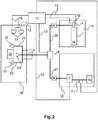
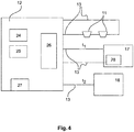
- the FIG. 4 shows in conjunction with FIG. 1
- the fire alarm and / or extinguishing control center has a control unit 24.
- the fire alarm and / or extinguishing control center at least one signal processing unit 25, in particular a microcontroller or a digital signal processor and preferably an operating and display unit 26.
- the memory of the fire alarm and / or extinguishing control center in which the discharge time t c , the control time t k and the monitoring time t b are stored.
- FIG. 1 shows the schematic representation of the system according to the invention for the deletion of objects and facilities with a first extinguishing agent supply device 17 a first extinguishing fluid, preferably a liquid synthetic extinguishing agent 14, in an extinguishing agent container 1, on which a valve 16 is arranged.
- the liquid synthetic extinguishing agent is superimposed with nitrogen.
- the nitrogen superposition pressure is 50 bar.
- the second arranged extinguishing agent supply device 18 comprises reservoir with a second extinguishing fluid, preferably a water reservoir 2 with water 3 or a water-based extinguishing agent and a conveyor 7, which generates the volume flow and pressure for the water or the water-based extinguishing agent.
- a second extinguishing fluid preferably a water reservoir 2 with water 3 or a water-based extinguishing agent and a conveyor 7, which generates the volume flow and pressure for the water or the water-based extinguishing agent.
- a first feed line 20 directs the liquid synthetic extinguishing agent 14 after opening the valve 16 by the fire alarm and / or extinguishing control center according to the invention to the separator 8 and a common pipe 9 and at least one nozzle 10.
- 3 nozzles are shown in the Schutzberiech 19 are located, in which the object to be protected, the object to be deleted 22 is applied in case of fire with extinguishing agent.
- the separator 8, the common pipe 9 and the nozzles 10 are formed to first guide the liquid synthetic extinguishing agent 14 and subsequently, if necessary, water 3 or water-based extinguishing agent to the object to be extinguished.
- FIG. 2 shows a variant of the system in which instead of the water storage tank 2, a water supply device 15 is arranged, preferably the public water supply, all other components and arrangements of this embodiment are identical to the in Fig. 1 illustrated plant.
- a water supply device 15 is arranged.
- the fire alarm and extinguishing control center 12 is designed and configured such that it controls the valve 16 and opens at the time t 1 when detecting a first fire signal, for discharging the first extinguishing fluid, preferably the liquid synthetic extinguishing agent 14, with the pressurized nitrogen from the extinguishing agent tank 1.
- the liquid synthetic extinguishing agent 14 passes through the common pipe 9 and the three nozzles 10 to the extinguishing object 20 in the protection area 19.
- the common pipe is designed and configured such that it controls the valve 16 and opens at the time t 1 when detecting a first fire signal, for discharging the first extinguishing fluid, preferably the liquid synthetic extinguishing agent 14, with the pressurized nitrogen from the extinguishing agent tank 1.
- the liquid synthetic extinguishing agent 14 passes through the common pipe 9 and the three nozzles 10 to the extinguishing object 20 in the protection area 19.
- the common pipe is designed and configured such that it controls the valve 16 and opens at the time
- Distribution pipe network 23 which directs the extinguishing agent to the nozzles 10, which are arranged around the protective object 22 in predefined positions.
- the predefined positions are determined so that the fire can be extinguished in a very short time with a minimum amount of extinguishing agent.
- the fire alarm and / or extinguishing control center 12 controls the fire alarm and / or extinguishing control center 12 additionally to the conveyor 7, which the second extinguishing fluid, preferably the water 3 or the water-based extinguishing agent, I from the reservoir 2 for the embodiment of Fig. 1 or discharges water from the water supply device 15 via the common pipe 9 and the nozzles 10 for deletion of the object 22 in the protection area 19.
- the second extinguishing fluid preferably the water 3 or the water-based extinguishing agent
- a pressure monitoring device 4 is arranged on or in the extinguishing agent container 1.
- the necessary pressure and the volume flow for application are achieved by the conveyor 7.
- the level monitoring device 5 and pressure monitoring device 4 are signal-conducting, in the illustrated example via the signal-conducting connection 13, preferably designed as an electrical line, connected to the fire alarm and / or control center 12. Pressure and level are detected and monitored by the fire alarm and / or extinguishing control center 12. If predetermined limit values are undershot and / or exceeded, this is sent to a predetermined receiving and / or signaling device.
- the conveyor 7 generates the required for the discharge of the water 3 volume flow and pressure.
- the extinguishing agent container 1 with the liquid synthetic extinguishing agent 14 is connected to the separating device 8 via the first supply line 21 and the water-conveying device 7 or the water-based extinguishing agent is connected to the second supply line 22 to the separating device 8.
- the common pipe 9 directs the extinguishing agent to the nozzles 10 in the protection area 19.
- the separator 8 ensures that only one extinguishing agent is in the pipe 9 and the water 3 or the water-based extinguishing agent and the liquid synthetic extinguishing agent 14th kept separate.
- Fig. 1 shows that in front of the extinguishing agent supply means 17 and 18, that is downstream of the extinguishing agent supply devices 17, 18 backflow preventer 6 are arranged. They prevent ingress of water 3 or water-based extinguishing agent into the first extinguishing agent supply device 17 and a penetration of the liquid synthetic extinguishing agent 14 in the second extinguishing agent supply means 18. There is a respective backflow preventer 6 between the extinguishing agent container 1 and the separation device 8 and between the conveyor 7 and the Separating device 8 is arranged.
- the pipe 9 leads to the nozzles 10, which apply the liquid synthetic extinguishing agent 14 and, if necessary, the water 3 to the protected object to be deleted 20.
- the conveyor 7, the valve 16 on the extinguishing agent tank 1, and the separator 8 are connected to their control with the fire alarm and / or extinguishing control center 12 signal-conducting.
- this signaling connection 13 is realized via electrical lines that are monitored by the fire alarm and / or extinguishing control center 12 for wire breakage and / or short circuit to detect malfunction immediately and report. Not shown is the wireless execution version of the signal-conducting connection thirteenth
- the first and second extinguishing agent supply means 17, 18 are driven, ie the valve 16 is driven at a first fire signal, it opens the extinguishing agent tank 1 and at a second fire signal in the predetermined monitoring period t b , the conveyor 7 is driven.
- the respective extinguishing agent is discharged via the common pipe 9 and the nozzles 10 and the fire is fought on or in the object to be deleted 22.
- fire alarm and / or extinguishing control center 12 is designed and arranged so that it controls the separation device 8 in the event of detection of a second fire signal at time t 2 before driving the second extinguishing agent supply means 18, for generating a switching position of the separation device 8, which the transport path of the second quenching fluid, preferably of the water 3 or of the water-based quenching agent, in the direction of the common pipeline 9 and the nozzles 10 releases and the transport path of the first quenching fluid, preferably the liquid synthetic extinguishing agent 14, from the first extinguishing agent supply means 17 in the direction of the common pipe 9 and the nozzles 10 completely blocked.
- the transport path of the second quenching fluid preferably of the water 3 or of the water-based quenching agent
- This switching position of the separator is the secondary switching position of the separator 8, since the second stage of deletion with the second extinguishing fluid, preferably with water 3 or water-based extinguishing agent only in case of need, if the first stage of deletion with the first extinguishing fluid, preferably with the liquid synthetic extinguishing agent 14, has not led to the deletion and a second fire signal has been detected.
- the fire alarm and / or extinguishing control center 12 is further configured and arranged to perform a control of the separation device 8 to generate a switching position of the separation device 8, which the transport path of the first extinguishing fluid, preferably the liquid synthetic extinguishing agent 14 prior to the activation of the first extinguishing agent supply means 17 , in the direction of the common pipe 9 and the at least one nozzle 10 releases and completely blocks the transport path of the second extinguishing fluid, preferably the water 3 or the water-based extinguishing agent from the second extinguishing agent supply device 18 in the direction of the common pipe 9 and the at least one nozzle 10.
- This switching position of the separating device is the primary switching position of the separating device 8, since the first stage of the deletion with the first quenching fluid, preferably the liquid synthetic extinguishing agent 14, takes place.
- This activation of the separating device 8 can be omitted if it is already in this primary switching position before the activation of the first extinguishing agent supply device 17.
- the remaining nitrogen flows and removes all residues of the synthetic extinguishing agent 14 from the pipeline 9.
- a rinsing of the common pipe 9 and the at least one nozzle 10 with a gas in this embodiment with nitrogen.
- Fig. 3 schematically shows the timing of the method steps of a particularly preferred embodiment of the method according to the invention using two different liquid extinguishing agents 3, 14, which are provided by two separate extinguishing agent supply means 17, 18 via a separator 8 and a common pipe 9 and at least one nozzle 10, shown.
- the second extinguishing agent supply means 18 in one Reservoir the second extinguishing fluid, preferably in a water reservoir 2 or from a water supply device 15 water 3 or water-based extinguishing agent ready.
- a first fire signal is detected by at least one event detector 11 and a fire alarm and / or extinguishing control center 12.
- the activation of the second extinguishing agent supply device 18 and the second extinguishing fluid, preferably the water 3 or the water-based extinguishing agent is via the separator 8, the common pipe 9 and the at least one nozzle 10 for deletion discharged.
- the control of the second extinguishing agent supply device 18 takes place in this case only if the time t 2 after complete or partial emptying of the extinguishing medium container 1, after expiry of the discharge time t c is, however, within a monitoring period t b, wherein the monitoring period of time t b from the time t 1 starting from the sum of the emptying time t c and a control time t k , wherein the control time t k is following the emptying time t c and in this time t k the fire alarm and / or extinguishing control center (12) checks whether a fire signal is detected and the time t 2 satisfies the inequality (t 1 + t c ) ⁇ t 2 ⁇ (t 1 + t b ).
Description
Die Erfindung betrifft eine Brandmelder- und/oder Löschsteuerzentrale zur Ansteuerung von zwei Löschmittelversorgungseinrichtungen und ein Verfahren zur Steuerung von zwei Löschmittelversorgungseinrichtungen.The invention relates to a fire alarm and / or extinguishing control center for controlling two extinguishing agent supply devices and a method for controlling two extinguishing agent supply devices.
Die Erfindung ist überall dort anwendbar wo für Maschinen, Anlagen und Einrichtungen in Räumen und offenen Bereichen ein effizientes, umweltverträgliches, sicheres und kostengünstiges Löschen eines Brandes mit zwei Löschmittelversorgungseinrichtungen erforderlich sind und deren Steuerung durch eine Brandmelder- und/oder Löschsteuerzentrale erfolgt.The invention is applicable everywhere where an efficient, environmentally friendly, safe and cost-effective extinguishing a fire with two extinguishing agent supply facilities are required for machines, equipment and facilities in rooms and open areas and their control is performed by a fire alarm and / or extinguishing control center.
Für den Schutz von Maschinen, Anlagen und Einrichtungen in großen Räumen und offenen Bereichen werden derzeit Wasserlöschanlagen, CO2- Löschanlagen und Pulverlöschanlagen verwendet. Der Einsatz von Löschgasen, wie Argon, Stickstoff und synthetischen Löschmitteln in gasförmiger Form, wie z.B. HFC-227ea, setzt einen dichten umschlossenen Raum voraus, was in der Regel bei Anwendungen in großen und offenen Räumen nicht gegeben ist. Weiterhin ist bei diesen Raumgrößen ein wirtschaftlicher Einsatz dieser Löschmittel nicht möglich.For the protection of machinery, equipment and facilities in large spaces and open areas, water extinguishing systems, CO 2 extinguishing systems and powder extinguishing systems are currently being used. The use of quenching gases, such as argon, nitrogen, and synthetic gaseous quenching agents, such as HFC-227ea, requires a dense, enclosed space, which is typically not found in large and open space applications. Furthermore, an economic use of this extinguishing agent is not possible with these room sizes.
Bei vielen dieser Objektschutzanwendungen ist die Verwendung von Wasser, von wasserbasierte Löschmittel, beispielsweise Wasser mit Zusatzmittel wie z.B. Netz- und Schaummitteln, von Pulverlöschmitteln und CO2 mit deutlichen Nachteilen verbunden. Wasser führt zu Kurzschlüssen, fördert Korrosion und muss, wenn es mit Brandfolgeprodukten kontaminiert ist, gezielt aufgefangen und entsorgt werden.
Mit dem Einsatz von Wassernebelanlagen wird durch Erzeugung von Wassertröpfchen mit sehr kleinem Durchmesser versucht, einen höheren Löscheffekt bei gleichzeitiger Reduktion der Löschwassermenge zu erzielen, aber die physikalischen Eigenschaften des Medium Wassers, insbesondere die durch die Thermik des Brandes beeinflussten Flugbahnen der Wassertröpfchen, schränken auch diese Anwendungen ein.In many of these object protection applications, the use of water, water-based extinguishing agents, such as water with additives such as wetting and foaming agents, powder extinguishing agents and CO 2 with significant disadvantages. Water causes short circuits, promotes corrosion and, if contaminated with subsequent fire products, must be specifically collected and disposed of.
With the use of water mist systems, by producing very small diameter water droplets, it is attempted to achieve a higher extinguishing effect while reducing the quantity of extinguishing water, but the physical properties of the medium water, especially the trajectories of the water droplets affected by the thermal fires, also limit these Applications.
Das rückstandsfreie CO2 führt bereits in geringer Konzentration zur Gefährdung von Personen und ist bei höherer Konzentration tödlich.The residue-free CO 2 already leads to endangering people in a low concentration and is lethal at higher concentrations.
Vor dem Halonverbot (der Einsatz von Halonen ist in manchen Ländern außerhalb der EU und mit Sonderbewilligung auch noch innerhalb der EU noch gestattet) wurde für viele dieser Anwendungen das synthetische Löschgas Halon 1211 verwendet. Das elektrisch nicht leitfähige, rückstandsfreie, und unter Umgebungsdruck gasförmige Halon 1211 könnte aufgrund seiner Eigenschaften bzw. seines Löschmechanismus auch für den Schutz von Objekten in offenen Bereichen verwendet werden.Prior to the halon ban (Halon is still permitted in some non-EU countries and with special permits within the EU), the synthetic extinguishing gas Halon 1211 has been used for many of these applications. The electrically non-conductive, residue-free, and ambient-pressure gaseous halon 1211 could also be used for the protection of objects in open areas because of its properties or its extinguishing mechanism.
Die von der chemischen Industrie entwickelten synthetischen Halon Nachfolgeprodukte als Löschmittel sind primär für die Anwendung in gasförmiger Phase und für den Einsatz in dichten geschlossenen Räumen im Raumschutzkonzept ausgelegt. Dieser Ansatz ergibt sich primär durch den Löschmechanismus dieser synthetischen Löschmittel der, im Gegensatz zu der chemischen Kettenabbruchreaktion von Halonen, auf Wärmeentzug beruht. Um diesen Effekt des Wärmeentzuges zu erzielen, ist zur sicheren Löschung eines energetischen Feuers eine längere Verweilzeit des synthetischen Löschmittels an der Flamme, eine längere Einwirkzeit des Löschmittels erforderlich.The synthetic halon successor products developed by the chemical industry as extinguishing agents are primarily designed for use in gaseous phase and for use in tight closed rooms in the room protection concept. This approach is primarily due to the quenching mechanism of these synthetic quenchers which, unlike the chemical chain termination reaction of halons, relies on heat removal. In order to achieve this effect of the heat extraction, a longer residence time of the synthetic extinguishing agent at the flame, a longer exposure time of the extinguishing agent is required to safely extinguish an energetic fire.
Bis heute gibt es auf dem Markt kein System und keine Lösung mit synthetischen Löschmitteln, das sich für einen Objekt- und Einrichtungsschutz in der beschriebenen Form verwenden lässt. Das Hautaugenmerk aller auf dem Markt befindlichen und bekannten Systeme liegt in der Optimierung der Verdampfung der flüssig bevorrateten synthetischen Löschmittel an den Düsen um möglichst schnell in einem dichten geschlossenen Raum eine löschwirksames homogenes gasförmige Löschmittel - Luftgemisch zu erhalten, das dem Feuer rasch Wärme entziehen kann.To date, there is no system on the market and no solution with synthetic extinguishing agents that can be used for object and device protection in the form described. The main focus of all on the market and known systems is to optimize the evaporation of liquid stored synthetic extinguishing agent at the nozzles to get as fast as possible in a dense closed space a löwirksames homogeneous gaseous extinguishing agent - air mixture that can quickly extract heat from the fire.
Aus
Weiterhin nachteilig an bekannten Anlagen dieser Art und deren Ansteuerung ist, dass nur ein begrenztes Volumen an flüssigem synthetischem Löschmittel zur Verfügung gestellt werden kann, und nach erfolgtem Löschvorgang und vollständigem Verbrauch des flüssigen synthetischen Löschmittels bei Rückzündungen und Wiederaufflammen des Feuers keine weitere Löschung erfolgen kann.Another disadvantage of known systems of this type and their control is that only a limited volume of liquid synthetic extinguishing agent can be provided, and after extinguishing and complete consumption of the liquid synthetic extinguishing agent in the case of reignitions and re-firing of the fire no further deletion can take place.
Im Gegensatz dazu muss bei einer erforderlichen schnellen Löschung bei Objektschutzanwendungen möglichst viel synthetisches Löschmittel in flüssiger Form direkt in die Wirkzone eingebracht werden. Eine Verdampfung des flüssigen synthetischen Löschmittels an der Düse würde einen Verlust von Löschwirkung, von Einwirkzeit des Löschmittels in der Wirkzone bedeuten. Es müssen aber auch Steuerungsvorrichtungen vorhanden sein, welche nach erfolgter Abgabe der gesamten Menge des zur Verfügung stehenden synthetischen Löschmittels Feuersignale erfassen können, falls das Feuer nicht gelöscht wurde, oder wieder aufflammt und welche in diesem Fall eine zweite wasserbasierte Löschanlage ansteuert.In contrast, in the case of a required rapid extinguishment in object protection applications, as much synthetic extinguishing agent in liquid form must be introduced directly into the active zone. Evaporation of the liquid synthetic extinguishing agent at the nozzle would mean a loss of extinguishing effect, of exposure time of the extinguishing agent in the zone of action. However, there must also be control devices which can detect fire signals after delivery of the entire amount of available synthetic extinguishing agent, if the fire was not deleted, or flares up again and which in this case controls a second water-based extinguishing system.
Im Sinne der Erfindung wird unter dem Begriff Wirkzone der Ort der Entfaltung der Löschwirkung verstanden, die Flamme und/oder die Verbrennungszone und/oder den Brandherd. Im Fall des flüssigen synthetischen Löschmittels liegt der Löscheffekt in der Kühlung (Wärmeenergieentzug) und beim Übergang des flüssigen Löschmittels in die gasförmige Phase erfolgt die lokale Sauerstoffverdrängung.For the purposes of the invention, the term effective zone is understood to mean the location of the development of the extinguishing effect, the flame and / or the combustion zone and / or the source of the fire. In the case of liquid synthetic extinguishing agent is the extinguishing effect in the cooling (heat energy removal) and the transition of the liquid extinguishing agent in the gaseous phase, the local oxygen displacement occurs.
Ausgehend von diesem Stand der Technik ist es daher Aufgabe der Erfindung eine sichere, umweltfreundliche und kostengünstige Lösung zum schnellen und sicheren Löschen von Objekten oder von Einrichtungen in Räumen, insbesondere in großen oder offenen Räumen zu entwickeln bei der ein synthetisches Löschmittel in begrenzter Menge eingesetzt wird, intensiv wirkt und einen Brand auch nach dem Verbrauch des flüssigen synthetischen Löschmittels zuverlässig löscht.Based on this prior art, it is therefore an object of the invention to provide a safe, environmentally friendly and cost-effective solution for fast and secure deletion of To develop objects or facilities in rooms, especially in large or open spaces in which a synthetic extinguishing agent is used in a limited amount, acts intensively and reliably extinguishes a fire even after the consumption of liquid synthetic extinguishing agent.
Diese Aufgabe wird durch eine Brandmelder- und/oder Löschsteuerzentrale nach den Merkmalen des ersten Patenanspruches sowie durch ein Verfahren nach Anspruch 12 gelöst.This object is achieved by a fire alarm and / or extinguishing control center according to the features of the first patent claim and by a method according to
Unteransprüche geben vorteilhafte Ausgestaltungen der Erfindung wieder.Subclaims give advantageous embodiments of the invention again.
Die erfindungsgemäße Lösung betrifft eine Brandmelder- und/oder Löschsteuerzentrale zur Ansteuerung von zwei Löschmittelversorgungseinrichtungen.The inventive solution relates to a fire alarm and / or extinguishing control center for controlling two extinguishing agent supply devices.
Die erste Löschmittelversorgungseinrichtung der zwei Löschmittelversorgungseinrichtungen weist vorzugsweise mindestens einen Löschmittelbehälter auf. Die zweite Löschmittelversorgungseinrichtung der zwei Löschmittelversorgungseinrichtungen weist vorzugsweise mindestens einen Vorratsbehälter auf.The first extinguishing agent supply device of the two extinguishing agent supply devices preferably has at least one extinguishing agent container. The second extinguishing agent supply device of the two extinguishing agent supply devices preferably has at least one storage container.
Erfindungsgemäß weist die Brandmelder- und/oder Löschsteuerzentrale eine Steuereinheit auf, die dazu eingerichtet ist nach der Ansteuerung einer ersten Löschmittelversorgungseinrichtung (17) bei Erfassung eines ersten Feuersignals zum Zeitpunkt t1, bei Erfassung eines zweiten Feuersignals zum Zeitpunkt t2 eine zweite Löschmittelversorgungseinrichtung anzusteuern wenn sie geprüft hat, ob der Zeitpunkt t2 die Ungleichung (t1+tc) < t2 < (t1+tb) erfüllt , wobei tc die Entleerungszeit der vollständigen Entleerung mindestens eines Löschmittelbehälters (1) der ersten Löschmittelversorgungseinrichtung, tk die Kontrollzeit im Anschluss an die Entleerungszeit tc und tb die Überwachungszeitdauer darstellen und die Überwachungszeitdauer tb ab dem Zeitpunkt t1 beginnend die Summe der Entleerungszeit tc und der Kontrollzeit tk ist.According to the invention, the fire alarm and / or extinguishing control center on a control unit which is adapted to the activation of a first extinguishing agent supply means (17) upon detection of a first fire signal at time t 1 , upon detection of a second fire signal at time t 2 to control a second extinguishing agent supply device if it has checked whether the time t 2 satisfies the inequality (t 1 + t c ) <t 2 <(t 1 + t b ), where t c is the emptying time of the complete emptying of at least one extinguishing agent container (1) of the first extinguishing agent supply device, t k is the monitoring time after the emptying time t c and t b represent the monitoring period and the monitoring period t b starting from the time t 1 is the sum of the emptying time t c and the control time t k .
Die erste Löschmittelversorgungseinrichtung weist ein erstes Löschfluid in vorzugsweise mindestens einem Löschmittelbehälter auf, vorzugsweise ein flüssiges synthetisches Löschmittel. In einer alternativen Ausführung wird der mindestens eine Löschmittelbehälter nicht vollständig, sondern teilweise entleert.The first extinguishing agent supply device has a first extinguishing fluid in preferably at least one extinguishing agent container, preferably a liquid synthetic extinguishing agent. In an alternative embodiment, the at least one extinguishing agent container is not completely, but partially emptied.
Die zweite Löschmittelversorgungseinrichtung weist ein zweites Löschfluid in vorzugsweise mindestens einem Vorratsbehälter auf, vorzugsweise Wasser oder wasserbasiertes Löschmittel in einem als Wasservorratsbehälter ausgeprägten Vorratsbehälter. In einer alternativen Ausführung umfasst die erste Löschmittelversorgungseinheit in mindestens einem Löschmittelbehälter ein Löschgas, insbesondere Inertgas oder ein Gasgemisch, welches durch die erste Löschmittelversorgungseinheit zur Löschung bereitgestellt wird.
Die erfindungsgemäße Brandmelder- und/oder Löschsteuerzentrale und das erfindungsgemäße Verfahren sind nicht beschränkt auf die Ansteuerung einer ersten Löschmittelversorgungseinheit mit flüssigem synthetischem Löschmittel als erstes Löschfluid und einer zweiten Löschmittelversorgungseinrichtung mit Wasser oder wasserbasiertem Löschfluid als zweites Löschfluid, sondern umfasst beliebige Kombinationen von ersten Löschfluiden der ersten und zweiten Löschfluiden der zweiten Löschmittelversorgungseinrichtung. Im Weiteren wird die erfindungsgemäße Brandmelder- und/oder Löschsteuerzentrale und das Verfahren zur Steuerung von zwei Löschmittelversorgungseinrichtungen im Wesentlichen mit einer bevorzugte Ausführung mit einem flüssigen synthetischen Löschmittel in mindestens einem Löschmittelbehälter der ersten Löschmittelversorgungseinrichtung und Wasser oder wasserbasiertes Löschmittel in der zweiten Löschmittelversorgungsrichtung beschrieben.The second extinguishing agent supply device has a second extinguishing fluid in preferably at least one storage container, preferably water or water-based extinguishing agent in a reservoir which is in the form of a water reservoir. In an alternative embodiment, the first extinguishing agent supply unit comprises at least an extinguishing agent container, an extinguishing gas, in particular inert gas or a gas mixture, which is provided by the first extinguishing agent supply unit for deletion.
The inventive fire alarm and / or extinguishing control unit and the inventive method are not limited to the control of a first extinguishing agent supply unit with liquid synthetic extinguishing agent as the first extinguishing fluid and a second extinguishing agent supply device with water or water-based extinguishing fluid as a second extinguishing fluid, but includes any combinations of first extinguishing fluids of the first and second extinguishing fluids of the second extinguishing agent supply device. Furthermore, the fire alarm and / or extinguishing control unit according to the invention and the method for controlling two extinguishing agent supply devices is described essentially with a preferred embodiment with a liquid synthetic extinguishing agent in at least one extinguishing agent container of the first extinguishing agent supply device and water or water-based extinguishing agent in the second extinguishing agent supply direction.
Die Steuereinheit umfasst in einer bevorzugten Ausführung eine Signalverarbeitungseinheit insbesondere einen Mikrokontroller oder einen digitalen Signalprozessor. Diese Signalverarbeitungseinheit ist Bestandteil einer Auswerteeinheit zur Bewertung von Signalen der mit der Brandmelder- und/oder Löschsteuerzentrale verbundenen Ereignismelder. In einer vorteilhaften Ausführung umfasst die Steuereinheit mindestens zwei Module, ein erstes Modul, welches mit einer Auswerteeinheit ausgestattet ist und ein zweites Modul, welches Steuersignale zur Ansteuerung von Löschmittelversorgungseinrichtungen und/oder Abschaltungssignale generiert und vorzugsweise auch eine Signalverarbeitungseinheit umfasst. In einer weiteren bevorzugten Ausführung, sind in der Brandmelder- und/oder Löschsteuerzentrale mindestens eine Signalverarbeitungseinheit und optional Speicher angeordnet, welche signalleitend mit dem ersten und zweiten Modul und vorzugsweise mit weiteren Modulen der Brandmelder- und/oder Löschsteuerzentrale verbunden sind.In a preferred embodiment, the control unit comprises a signal processing unit, in particular a microcontroller or a digital signal processor. This signal processing unit is part of an evaluation unit for evaluating signals associated with the fire alarm and / or extinguishing control panel event reporting. In an advantageous embodiment, the control unit comprises at least two modules, a first module which is equipped with an evaluation unit and a second module which generates control signals for controlling extinguishing agent supply devices and / or shutdown signals and preferably also comprises a signal processing unit. In a further preferred embodiment, at least one signal processing unit and optionally memory are arranged in the fire alarm and / or extinguishing control center, which are signal-conducting connected to the first and second module and preferably with other modules of the fire alarm and / or extinguishing control center.
Das Verfahren zum Löschen von Objekten oder Einrichtungen umfasst folgende vorzugsweise hintereinander ablaufende Verfahrensschritte:
- (a) Erfassen eines ersten Feuersignals, insbesondere durch mindestens einen Ereignismelder und eine Brandmelder- und/oder Löschsteuerzentrale zum Zeitpunkt t1,
- (b) Ansteuern einer ersten Löschmittelversorgungseinrichtung, insbesondere durch die Brandmelder- und/oder Löschsteuerzentrale, zum Ausbringen eines ersten Löschfluids, vorzugsweise von flüssigem synthetischen Löschmittel, insbesondere über eine Trennstation, eine gemeinsame Rohrleitung und mindestens eine Düse,
- (c) Erfassen eines zweiten Feuersignals zum Zeitpunkt t2, und
- (d) Ansteuern einer zweiten Löschmittelversorgungseinrichtung, und Austragen von einem zweiten Löschfluid, vorzugsweise Wasser oder wasserbasiertem Löschmittel, insbesondere über die Trennvorrichtung, die gemeinsame Rohrleitung und die mindestens eine Düse, zur Löschung.
- (a) detecting a first fire signal, in particular by at least one event detector and a fire alarm and / or extinguishing control panel at the time t 1 ,
- (b) activating a first extinguishing agent supply device, in particular by the fire detection and / or extinguishing control center, for discharging a first extinguishing fluid, preferably of liquid synthetic extinguishing agent, in particular via a separation station, a common pipeline and at least one nozzle,
- (c) detecting a second fire signal at time t 2 , and
- (D) driving a second extinguishing agent supply means, and discharging a second extinguishing fluid, preferably water or water-based extinguishing agent, in particular via the separator, the common pipe and the at least one nozzle, for extinction.
Das flüssige synthetische Löschmittel wird vorzugsweise aus einem oder mehreren Löschmittelbehältern und/oder aus der bevorratenden Rohrleitung, welche mit dem flüssigen synthetischen Löschmittel gefüllt ist, ausgebracht.
Das Verfahren ist besonders geeignet zum Löschen von Objekten oder Einrichtungen wie Maschinen oder Anlagen in großen und/oder offenen Räumen. Räume oder offenen Räume mit den zu schützenden Objekten oder Einrichtungen stellen die Schutzbereiche dar.
Die flüssigen Löschmittel werden über die gemeinsame Rohrleitung zu mindestens einer Düse geleitet und über diese auf den Brandherd in der Nähe oder am Objekt oder der Einrichtung im Schutzbereich ausgebracht um das Feuer zu löschen. In der Regel sind mehrere Düsen angeordnet, die Anzahl richtet sich nach Größe und Form des Objektes oder der Einrichtung und der Größe des Schutzbereiches. Wenn im Weiteren, insbesondere in den Patentansprüchen von nur einer Düse die Rede ist, dann ist immer mindestens eine Düse gemeint, d.h. auch einen Vielzahl von Düsen. Wenn im Weiteren vom 2. Löschmittel Wasser oder nur von Wasser die Rede ist, dann ist immer auch als Alternative wasserbasiertes Löschmittel gemeint. Wenn mehr als eine Düse angeordnet ist, dann beinhaltet die gemeinsame Rohrleitung ein Verteilungsrohrnetz, welches die Löschmittel zu den Düsen leitet, die um das schützende Objekt oder die Einrichtung in vordefinierten Positionen angeordnet sind.The liquid synthetic extinguishing agent is preferably discharged from one or more extinguishing agent containers and / or from the storing pipe which is filled with the liquid synthetic extinguishing agent.
The method is particularly suitable for the deletion of objects or devices such as machines or plants in large and / or open spaces. Rooms or open spaces with the objects or facilities to be protected represent the protected areas.
The liquid extinguishing agents are routed through the common pipe to at least one nozzle and spread over this to the fire in the vicinity or on the object or device in the protected area to extinguish the fire. As a rule, several nozzles are arranged, the number depends on the size and shape of the object or the device and the size of the protected area. If in the following, in particular in the claims of only one nozzle is mentioned, then always at least one nozzle is meant, ie, a plurality of nozzles. If in the following from the second extinguishing agent water or only water is mentioned, then always as an alternative meant water-based extinguishing agent. If more than one nozzle is located, then the common pipe includes a distribution pipe network which directs the extinguishing agent to the nozzles disposed about the protective object or device in predefined positions.
Bei der Verwendung von mehreren Düsen weist die gemeinsame Rohrleitung Abzweigungen, ein Verteilungsrohrnetz zu den Düsen auf und ggf. zu anderen Schutzbereichen. Unter einer gemeinsamen Rohrleitung wird deshalb im Weiteren auch ein solches Rohrleitungsnetz verstanden, das für beide flüssige Löschmittel zum Ausbringen über die Düsen genutzt wird.When using multiple nozzles, the common pipe has branches, a distribution pipe network to the nozzles and possibly to other protection areas. A common pipeline is therefore also understood below to mean such a pipeline network which is used for both liquid extinguishing agents for discharging via the nozzles.
In einer alternativen Ausführung dient die Rohrleitung bzw. das Rohrnetz zu den Düsen als Löschmittelbehälter. Hierbei wird die Rohrleitung mit einem Auslöseventil verschlossen. Das Auslöseventil befindet sich direkt im Schutzbereich und die Düsen werden mit kurzen Strangleitungen angeschlossen. Das Auslöseventil umfasst ein Auslöseelement welches insbesondere auf die Brandkenngröße Wärme reagiert. Alternativ wird das Auslöseventil mit einem elektrischen Auslöser versehen, beispielsweise mit einem Magnethubkolben oder einem pyrotechnischem Auslöser. Der pyrotechnische Auslöser stellt ein elektrisch zündbares pyrotechnisches Element dar, welches eine Krafteinwirkung zur Auslösung ausübt.In an alternative embodiment, the pipeline or the pipe network to the nozzles serves as an extinguishing agent container. Here, the pipeline is closed with a trigger valve. The Trigger valve is located directly in the protection area and the nozzles are connected with short branch lines. The triggering valve comprises a triggering element which reacts in particular to the fire characteristic heat. Alternatively, the trigger valve is provided with an electrical release, for example with a magnetic piston or a pyrotechnic release. The pyrotechnic trigger is an electrically ignitable pyrotechnic element, which exerts a force to trigger.
In einer weiteren alternativen Ausführung, wird alternativ zu einem Auslöseventil die Rohrleitung oder das Rohrnetz mit Sprinklerdüsen, die ein Glasfass umfassen, verschlossen, wobei die Glasfässer der Sprinkler durch Auslöseelemente, beispielsweise Magnethubkolben oder einen pyrotechnischen Auslöser geöffnet werden. Der Vorteil dieser Lösung liegt in der kurzen Flutungszeit.In a further alternative embodiment, as an alternative to a trigger valve, the pipeline or the pipe network is closed with sprinkler nozzles which comprise a glass barrel, the glass barrels of the sprinklers being opened by triggering elements, for example magnetic lifting pistons or a pyrotechnic trigger. The advantage of this solution lies in the short flooding time.
Somit kann das Verfahren zum Löschen von Objekten oder Einrichtungen mit den oben genannten Verfahrensschritten (a) bis (d) alternativ mit einer Rohrleitung bzw. das Rohrnetz zu den Düsen als Löschmittelbehälter ausgebildet und das flüssige synthetische Löschmittel enthaltend durchgeführt werden, wobei die Rohrleitung oder das Rohrleitungsnetz mit Auslöseventil und/oder Sprinklern verschlossen sind und die Sprinkler im Brandfall durch eine Auslöseeinrichtung (Magnethubkolben/pyrotechnischer Auslöser) aktiviert werden.Thus, the method for extinguishing objects or devices with the above-mentioned process steps (a) to (d) may alternatively be formed with a pipe to the nozzles as the extinguishant container and containing the liquid synthetic extinguishing agent, wherein the pipe or the Piping network are closed with release valve and / or sprinklers and the sprinklers are activated in case of fire by a trigger device (magnetic piston / pyrotechnic release).
In einer vorteilhaften Ausführung des Verfahrens stellt das flüssige synthetische Löschmittel eine nicht brennbare, nicht entflammbare, elektrisch nicht leitende Flüssigkeit mit einem Dampfdruck bei 21°C von 0,1 bis zu 3 bar dar und/oder bei einer Temperatur von 21°C, eine Dichte 1.400 kg/m3 bis 1.800 kg/m3 aufweist.In an advantageous embodiment of the method, the liquid synthetic extinguishing agent is a non-flammable, non-flammable, electrically non-conductive liquid having a vapor pressure at 21 ° C of 0.1 to 3 bar and / or at a temperature of 21 ° C, a Density 1,400 kg / m 3 to 1,800 kg / m 3 has.
In einer weiteren vorteilhaften Ausführung des Verfahrens stellt das flüssige synthetische Löschmittel ein FK-5-1-12 (C4F9OCH3) dar. Hierbei handelt es sich um das unter dem Markennamen NOVEC 1230 bekannte Löschmittel, welches in der ASHRAE- Nomenklatur FK 5 -1-12 ist. Es ist in den Standards NFPA 2001 und ISO 14520 gelistet und wird auch durch die chemischen Formeln (C4F9OCH3) oder 1,1,1,2,2,4,5,5,5-NONAFLUORO-4-(TRIFLUOROMETHYL)-3-PENTANONE beschrieben.In a further advantageous embodiment of the method, the liquid synthetic extinguishing agent is a FK-5-1-12 (C 4 F 9 OCH 3 ). This is the known under the brand name NOVEC 1230 extinguishing agent, which in the ASHRAE nomenclature FK is 5 -1-12. It is listed in standards NFPA 2001 and ISO 14520 and is also represented by the chemical formulas (C 4 F 9 OCH 3 ) or 1,1,1,2,2,4,5,5,5-NONAFLUORO-4- ( TRIFLUOROMETHYL) -3-PENTANONE.
In einer weiteren vorteilhaften Ausführung des Verfahrens stellt das flüssige synthetische Löschmittel ein Fluorketon dar.In a further advantageous embodiment of the method, the liquid synthetic extinguishing agent is a fluoroketone.
In einer weiteren Ausführungsvariante des Verfahrens wird durch die Ansteuerung der ersten Löschmittelversorgungseinrichtung durch die Brandmelder- und/oder Löschsteuerzentrale zum Ausbringen des ersten Löschfluids, vorzugsweise des flüssigen synthetischen Löschmittels, insbesondere aus dem Löschmittelbehälter über die Rohrleitung und die mindestens eine Düse, das flüssige synthetische Löschmittel mittels druckbeaufschlagtem Gas, vorzugsweise Stickstoff, aus dem Löschmittelbehälter durch die gemeinsame Rohrleitung zu der Düse getrieben. Hierzu sendet die Brandmelder- und/oder Löschsteuerzentrale ein Steuersignal an ein Ventil und/oder an einen Vorrichtung zur Druckbeaufschlagung des flüssigen synthetischen Löschmittels im Löschmittelbehälter. In einer vorteilhaften Ausführung überlagert das druckbeaufschlagte Gas das flüssige synthetische Löschmittel im Löschmittelbehälter der ersten Löschmittelversorgungseinrichtung. Der Druck des druckbeaufschlagten Gases im Löschmittelbehälter (1) beträgt 25, 42 oder 50 bar.In a further embodiment of the method is by the control of the first extinguishing agent supply device by the fire alarm and / or extinguishing control center for discharging the first extinguishing fluid, preferably the liquid synthetic extinguishing agent, in particular from the extinguishing agent container via the pipe and the at least one nozzle, the liquid synthetic extinguishing agent by means of pressurized gas, preferably nitrogen, driven from the extinguishing agent container through the common pipe to the nozzle. For this purpose, the fire alarm and / or extinguishing control center sends a control signal to a valve and / or to a device for pressurizing the liquid synthetic extinguishing agent in the extinguishing agent container. In an advantageous embodiment, the pressurized gas superimposed on the liquid synthetic extinguishing agent in the extinguishing agent container of the first extinguishing agent supply device. The pressure of the pressurized gas in the extinguishing agent tank (1) is 25, 42 or 50 bar.
Der Löschmittelbehälter ist mit einem Ventil verschlossen, welches bei Ansteuerung durch die Brandmelder- und Löschsteuerzentrale den Löschmittelbehälter öffnet und das Löschmittel ausgebracht werden kann.The extinguishing agent container is closed with a valve which opens the extinguishing agent container when actuated by the fire alarm and extinguishing control panel and the extinguishing agent can be discharged.
In einer weiteren vorteilhaften Ausführung des Verfahrens erfolgt nach dem Verfahrensschritt (b), eine Spülung der gemeinsamen Rohrleitung und der Düse bzw. Düsen mit einem Gas, vorzugsweise Stickstoff. Vorzugsweise erfolgt dies mit dem restlichen druckbeaufschlagtem Gas aus dem Löschmittelbehälter für das flüssige synthetische Löschmittel. Dies hat den Vorteil, dass die gemeinsame Rohrleitung und die Düsen keine oder äußerst geringe Mengen des flüssigen synthetischen Löschmittels aufweisen und damit eine Reaktion mit dem zweiten flüssigen Löschmittel, vorzugsweise Wasser oder wasserbasiertes Löschmittel vermieden wird und damit auch Korrosion in der gemeinsamen Rohrleitung und in Löschmittel durchleitenden Komponenten vermieden wird.In a further advantageous embodiment of the method takes place after the process step (b), a flushing of the common pipe and the nozzle or nozzles with a gas, preferably nitrogen. This is preferably done with the remaining pressurized gas from the extinguishing agent container for the liquid synthetic extinguishing agent. This has the advantage that the common pipe and the nozzles have no or very small amounts of the liquid synthetic extinguishing agent and thus a reaction with the second liquid extinguishing agent, preferably water or water-based extinguishing agent is avoided and thus corrosion in the common pipe and extinguishing agent passing components is avoided.
In einer weiteren vorteilhaften Ausgestaltung des Verfahrens wird das flüssige synthetische Löschmittel über eine Fördereinrichtung aus dem Löschmittelbehälter über die gemeinsame Rohrleitung und die mindestens eine Düse ausgetragen. Vorzugsweise werden eine oder mehrere Pumpen als Fördereinrichtung eingesetzt oder Druckerhöungseinrichtungen wie pyrotechnische Gasgeneratoren oder Aufladepatronen, die im Ansteuerungsfall bei Erfassung eines Feuersignals Gas mit einem vordefinierten Druck freisetzen, welches in den Löschmittelbehälter geleitet wird zum Austragen des flüssigen synthetischen Löschmittels. In diesen Ausführungen erfolgt die Ansteuerung der ersten Löschmittelversorgungseinrichtung durch die Brandmelder- und/oder Löschsteuerzentrale im erfindungsgemäßen Verfahrensschritt (b) durch das Versenden von Steuersignalen über die signalleitende Verbindung an die Fördereinrichtung.In a further advantageous embodiment of the method, the liquid synthetic extinguishing agent is discharged via a conveyor from the extinguishing agent tank via the common pipe and the at least one nozzle. Preferably, one or more pumps are used as a conveyor or pressure increasing devices such as pyrotechnic gas generators or charging cartridges that release in the driving case upon detection of a fire gas at a predefined pressure, which is passed into the extinguishing agent container for discharging the liquid synthetic extinguishing agent. In these embodiments, the control of the first extinguishing agent supply device by the fire alarm and / or extinguishing control center in the process step (b) according to the invention by sending control signals via the signal-conducting connection to the conveyor takes place.
Zur Erfassung eines Feuersignals ist im Schutzbereich, mindestens ein Ereignismelder vorhanden. Vorzugsweise sind diese Ereignismelder in der Nähe, am oder sogar im zu schützenden Objekt angeordnet. Unter einem Feuersignal wird die Detektion einer Brandkenngröße verstanden, die einen vorgegebenen Grenzwert überschreitet oder die manuelle Betätigung eines Handfeuermelders, der ein Feuersignal an die erfindungsgemäße Brandmelder - und/oder Löschsteuerzentrale sendet. Die Detektion einer Brandkenngröße erfolgt durch die Sensoren eines Ereignismelders, vorzugsweise eines automatischen Brandmelders.To detect a fire signal, at least one event detector is present in the protected area. Preferably, these event messages are located in the vicinity, on or even in the object to be protected. A fire signal is understood to mean the detection of a fire parameter which exceeds a predetermined limit value or the manual operation of a manual call point, which sends a fire signal to the fire alarm and / or extinguishing control panel according to the invention. The detection of a fire characteristic is carried out by the sensors of an event detector, preferably an automatic fire detector.
Unter Brandkenngrößen werden alle Kenngrößen wie z.B. Rauch, Wärme und Flammenstrahlung sowie Brandgase verstanden, die einen entstehenden oder ausgebrochenen Brand kennzeichnen. Sie beruhen auf der Messung physikalischer Messgrößen wie der Lichtstreuung an Rauchaerosolen und/oder der Temperatur, der elektromagnetische Strahlung, oder dem Nachweis von Brandgasen wie z.B. CO, NOx oder längerkettigen Kohlenwasserstoffen oder anderer schwelbrandkennzeichnender Stoffe. Alle Messgrößen, die zur Branderkennung dienen, werden im Weiteren als Brandkenngrößen bezeichnet.Fire characteristics are understood to mean all parameters such as smoke, heat and flame radiation as well as combustion gases that characterize a fire that has arisen or has broken out. They are based on the measurement of physical parameters such as light scattering of smoke aerosols and / or temperature, electromagnetic radiation, or the detection of combustion gases such as CO, NO x or longer-chain hydrocarbons or other schwelbrandkennzeichnender substances. All parameters which serve for fire detection are referred to below as fire characteristics.
Als Ereignismelder werden vorzugsweise Brandmelder im Schutzbereich angeordnet. Als Brandmelder werden, in Abhängigkeit von den zu erwartenden Brandkenngrößen in einem Schutzbereich, automatische Brandmelder, wie Rauchmelder, Wärmemelder, Flammenmelder, Funkenmelder, Brandgasmelder, Rauchansaugsysteme, und/oder manuell zu betätigende Handfeuermelder eingesetzt.Fire detectors in the protected area are preferably arranged as event detectors. As fire detectors, depending on the expected fire characteristics in a protected area, automatic fire detectors, such as smoke detectors, heat detectors, flame detectors, spark detectors, fire gas detectors, Rauchansaugsysteme, and / or manually operated manual call points are used.
Die Entscheidung ob es sich bei der Detektion einer Brandkenngröße um ein Feuersignal handelt wird vorzugsweise durch entsprechende Auswertealgorithmen in der elektronischen Auswerteeinheit des Ereignismelders, vorzugsweise des Brandmelders getroffen. Das Feuersignal kann auch einen Voralarm darstellen um geeignete Maßnahmen einzuleiten.The decision whether the detection of a fire parameter is a fire signal is preferably made by appropriate evaluation algorithms in the electronic evaluation unit of the event detector, preferably the fire detector. The fire signal can also be a pre-alarm to take appropriate action.
Vorzugsweise senden die Ereignismelder das Feuersignal über eine signalleitende Verbindung zur Brandmelder- und/oder Löschsteuerzentrale, die dann dieses Feuersignal erfasst.Preferably, the event alarms send the fire signal via a signal-conducting connection to the fire alarm and / or extinguishing control center, which then detects this fire signal.
Für die signalleitende Verbindung zwischen Ereignismelder und der erfindungsgemäßen Brandmelder- und/oder Löschsteuerzentrale sind vorzugsweise elektrische Leitungen vorgesehen. Alternativ oder zusätzlich erfolgt das Senden des Feuersignals mittels einer kabellosen Datenübertragung, beispielsweise per Funk, die signalleitende Verbindung stellt dann eine Funkverbindung dar.For the signal-conducting connection between the event detector and the fire alarm and / or extinguishing control panel according to the invention preferably electrical lines are provided. Alternatively or additionally, the transmission of the fire signal by means of a wireless data transmission, for example by radio, the signal-conducting connection is then a radio connection.
Die Entscheidung ob es sich bei der Detektion einer Brandkenngröße um ein Feuersignal handelt, kann auch durch entsprechende Auswertealgorithmen in einer Auswerteeinheit oder Steuereinheit der Brandmelder- und/oder Löschsteuerzentrale erfolgen, ebenso die Erfassung eines Feuersignals durch die manuelle Betätigung eines Handfeuermelders.The decision whether the detection of a fire parameter is a fire signal can also be carried out by appropriate evaluation algorithms in an evaluation unit or control unit of the fire detection and / or extinguishing control panel, as well as the detection of a fire signal by the manual operation of a manual call point.
In einer besonders bevorzugten Ausführung des Verfahrens zählt das Feuersignal als erfasst, wenn dies die Brandmelder- und/oder Löschsteuersignale als Feuersignal erfasst hat und eine Feueralarmierung anzeigt und/oder an eine ständig besetzte Stelle weiterleitet.In a particularly preferred embodiment of the method, the fire signal counts as detected if this has detected the fire alarm and / or extinguishing control signals as a fire signal and indicates a fire alarm and / or forwards to a constantly occupied place.
Die für das Verfahren verwendete erfindungsgemäße Brandmelderzentrale stellt eine Empfangs- und Steuerzentrale dar, welche die Ereignisse von verschiedenen Ereignismeldern insbesondere Feuersignale von Brandmeldern, die in dem oder mehreren Schutzbereichen angeordnet sind empfängt, auswertet und dann Folgeaktionen einleitet. Als Reaktion agiert die Brandmelderzentrale als Steuerzentrale und Anzeigeeinheit und kann als Folgeaktion verschiedene technische Einrichtungen ansteuern, beispielsweise:
Ansteuerung eines internen oder externen Anzeigetableau und Einzel und Sammelanzeigen, beispielsweise LEDs und Displays für Feuer- und Ereignismeldungen
- Weiterleitung einer Brandmeldung an die ständig besetzte Leitstelle zur Alarmierung der Feuerwehr
- Auslösung eines Räumungsalarms zur Räumung eines Gebäudes oder eines Teiles davon;
- Ansteuerung von Rauchabzugseinrichtungen und/oder von Feuerschutzabschlüssen;
- Abschaltung von zu schützenden Objekten und Einrichtungen wie beispielweise Maschinen, EDV-Einrichtungen;
- Ansteuerung einer Löschanlage oder einer Löschmittelversorgungsvorrichtung und Öffnen von Ventilen an Löschmittelbehältern und an/in löschfluidführenden Komponenten;
- Steuerung des Löschvorgangs.
Control of an internal or external display panel and individual and group displays, such as LEDs and displays for fire and event messages
- Forwarding of a fire alarm to the constantly occupied control center for alerting the fire brigade
- Triggering of an evacuation alert to evacuate a building or part thereof;
- Control of smoke extraction devices and / or fire protection closures;
- Shutdown of objects to be protected and facilities such as machinery, computer equipment;
- Activating an extinguishing system or an extinguishing agent supply device and opening valves on extinguishing agent containers and on / in extinguishing fluid-carrying components;
- Control of the deletion process.
Eine Löschsteuerzentrale ist signalleitend mit einer Brandmelderzentrale oder einer Überwachungszentrale oder einem Leitsystem verbunden, empfängt ein Feuersignal und steuert eine Löschanlage an, löst diese aus zur Ausbringung des Löschmittels im Schutzbereich, in welchem ein Brand detektiert wurde und steuert den Ablauf der Löschung, vorzugsweise durch Öffnen und gegebenenfalls durch Schließen von Ventilen an Löschmittelbehältern und/oder an/in löschfluidführenden Komponenten.
Eine Löschsteuerzentrale für Gaslöschanlagen oder Löschanlagen mit synthetischen Löschmitteln kann vorzugsweise voll oder teilweise die Anforderungen der EN12094-1 erfüllen.
Eine Brandmelder- und Löschsteuerzentrale ist eine kombinierte Zentrale, welche alle Komponenten aufweist um die genannten Funktionen und Wirkungsweise einer Brandmelderzentrale und einer Löschsteuerzentrale zu erfüllen.An extinguishing control center is signal-conducting connected to a fire alarm control panel or a control center or a control system, receives a fire signal and controls an extinguishing system, triggers this to apply the extinguishing agent in the protected area in which a fire was detected and controls the deletion process, preferably by opening and optionally closing valves on extinguishing agent containers and / or on / in extinguishing fluid-carrying components.
An extinguishing control panel for gas extinguishing systems or extinguishing systems with synthetic extinguishing agents may preferably fully or partially meet the requirements of EN12094-1.
A fire alarm and extinguishing control panel is a combined control center, which has all the components to meet the above functions and operation of a fire alarm and extinguishing control center.
Die erfindungsgemäße Brandmelder und/oder Löschsteuerzentrale weist vorzugsweise folgende besondere Merkmale auf.
Die Brandmelder- und/oder Löschsteuerzentrale führt alle für die Funktion der Anlage erforderlichen Überwachungen, Steuerungen, Regelungen, Alarmierungen, Ab- bzw. Einschaltungen durch. Sie kann in vorteilhaften Ausführungen alle Schalt- und Betriebszustände an vordefinierte Empfangseinrichtungen wie Gebäudeleitsysteme weiterleiten. Die Brandmelder- und/oder Löschsteuerzentrale ist sowohl mit der Fördereinrichtung als auch mit der Füllstands- und Drucküberwachungseinrichtung signalleitend verbunden. Weiterhin erfasst und verarbeitet die Brandmelder- und/oder Steuerzentrale die Signale der Ereignismelder. Darüber hinaus kann die Brandmelder- und/oder Löschsteuerzentrale auch mit der zu löschenden Maschinen, Anlagen und/oder Einrichtungen signalleitend verbunden sein und diese aus- oder einschalten.The fire detector and / or extinguishing control panel according to the invention preferably has the following special features.
The fire alarm and / or extinguishing control panel performs all necessary for the function of the system monitoring, controls, regulations, alarms, off or on by. In advantageous embodiments, it can forward all switching and operating states to predefined receiving devices, such as building management systems. The fire alarm and / or extinguishing control center is signal-conducting connected both to the conveyor and to the level and pressure monitoring device. Furthermore, the fire alarm and / or control center detects and processes the signals of the event report. In addition, the fire alarm and / or extinguishing control center may also be connected to the signal to be deleted machines, facilities and / or facilities and turn these off or on.
Die Steuereinheit der Brandmelder- und/oder Löschsteuerzentrale, die signaltechnisch mit der Auswerteeinheit der Feuersignale verbunden ist, leitet alle Folgeaktionen, alle Ansteuerungen ein.
Die Steuereinheit der Brandmelder- und/oder Löschsteuerzentrale kann über verschiedene Mittel, einen Personalcomputer, ein Tablet-Computer, ein Service- oder Programmiertool, programmiert und konfiguriert werden. Hierzu wird eine in oder an der Brandmelder- und/oder Löschsteuerzentrale vorhandene Programmierschnittstelle verwendet. Mit diesen Mitteln können Parameter wie Zeiten, insbesondere eine Entleerungszeit tc, eine Kontrollzeit tk eine Überwachungszeitdauert tb in einem Speicher der Steuereinheit und/oder der Brandmelder- und/oder Löschsteuerzentrale hinterlegt werden. Die vorzugsweise in der Signalverarbeitungseinheit der Steuereinheit gespeicherte Programmierung leitet dann die vorprogrammierten Folgeaktionen bei Erfassung von Feuersignalen ein, insbesondere die Ansteuerung von Löschmittelversorgungseinrichtungen.The control unit of the fire alarm and / or extinguishing control center, which is connected by signal technology with the evaluation of the fire signals, initiates all follow-up actions, all controls.
The control unit of the fire alarm and / or extinguishing control panel can be programmed and configured by various means, a personal computer, a tablet computer, a service or programming tool. For this purpose, an existing in or on the fire alarm and / or extinguishing control panel programming interface is used. With these means, parameters such as times, in particular an emptying time t c , a monitoring time t k, a monitoring time t b can be stored in a memory of the control unit and / or the fire alarm and / or extinguishing control center. The programming preferably stored in the signal processing unit of the control unit then forwards the preprogrammed follow-up actions when detecting fire signals, in particular the control of extinguishing agent supply devices.
Die im Mikrokontrollersystem der Steuereinheit, gespeicherte Programmierung enthält ein Prüfungsmodul, welches bei Erfassung eines zweites Feuersignals zum Zeitpunkt t2 ein Signal zur Ansteuerung einer zweiten Löschmittelversorgungseinrichtung generiert, wenn das Prüfungsmodul feststellt, dass der Zeitpunkt t2 die Ungleichung (t1+tc) < t2 < (t1+tb) erfüllt, wobei tc die Entleerungszeit der vollständigen oder teilweisen Entleerung des mindesten einen oder mehrerer Löschmittelbehälter der ersten Löchmittelversorgungseinheit , tk die Kontrollzeit im Anschluss an die Entleerungszeit tc und tb die Überwachungszeitdauer darstellen und die Überwachungszeitdauer tb ab dem Zeitpunkt t1 beginnend die Summe der Entleerungszeit tc und der Kontrollzeit tk ist.
In einer vorteilhaften Ausführung der Brandmelder- und/oder Löschsteuerzentrale weist die in einer Signalverarbeitungseinheit der Steuereinheit gespeicherte Programmierung ein Prüfungsmodul auf, welches bei Erfassung des zweites Feuersignals zum Zeitpunkt t2 ein Signal zur Ansteuerung der zweiten Löschmittelversorgungseinrichtung generiert, wenn das Prüfungsmodul feststellt, dass der Zeitpunkt t2 die Ungleichung (t1+tc) < t2 < (t1+tb) erfüllt.
In einer weiteren vorteilhaften Ausführung der Brandmelder- und/oder Löschsteuerzentrale weist die Brandmelder und/oder Löschsteuerzentrale einen Speicher auf und umfasst ferner eine Programmierschnittstelle, die ausgebildet und eingerichtet ist, dass über die Programmierschnittstelle mit einem Programmier- und/oder Konfigurationsmittel die Entleerungszeit tc, die Kontrollzeit tk und die Überwachungszeitdauert tb im Speicher hinterlegt werden.
In einer bevorzugten Ausgestaltung der Brandmelder- und/oder Löschsteuerzentrale stellen die Programmier- und/oder Konfigurationsmittel insbesondere einen Personalcomputer, ein Tablet-Computer, ein Notebook, ein Smartphone oder ein Service- oder Programmiertool dar.
In einer vorteilhaften Ausgestaltung ist die Brandmelder- und/oder Löschsteuerzentrale dazu eingerichtet, dass diese Parameter zusätzlich oder ausschließlich über die Bedienelemente der Anzeige- und Bedieneinheit der Brandmelder- und/oder Löschsteuerzentrale, eingegeben und/oder geändert werden können.The programming stored in the microcontroller system of the control unit contains a test module which generates a signal for activating a second extinguishing agent supply device when a second fire signal is detected at time t 2 when the test module determines that the time t 2 is the inequality (t 1 + t c ). <t 2 <(t 1 + t b ), where t c represents the discharge time of the complete or partial emptying of the at least one or more extinguishant containers of the first hole supply unit, t k is the control time following the purge time t c and t b is the monitoring period and the monitoring period t b starting from the time t 1 is the sum of the emptying time t c and the control time t k .
In an advantageous embodiment of the fire alarm and / or extinguishing control center, the stored in a signal processing unit of the control unit programming on a test module, which generates a signal for controlling the second extinguishing agent supply device upon detection of the second fire signal at time t 2 , if the test module determines that the Time t 2 satisfies the inequality (t 1 + t c ) <t 2 <(t 1 + t b ).
In a further advantageous embodiment of the fire detection and / or extinguishing control panel, the fire detector and / or extinguishing control panel in a memory, and further comprising a programming interface that is configured and arranged such that via the programming interface with a programming and / or configuring means the emptying time t c , the control time t k and the monitoring time t b are stored in the memory.
In a preferred embodiment of the fire alarm and / or extinguishing control center, the programming and / or configuration means represent in particular a personal computer, a tablet computer, a notebook, a smartphone or a service or programming tool.
In an advantageous embodiment, the fire alarm and / or extinguishing control panel is set up that these parameters can be entered and / or changed in addition or exclusively via the controls of the display and control unit of the fire alarm and / or extinguishing control panel.
In einer vorteilhaften Ausführung ist die zentrale Steuereinheit der Brandmelder- und/oder Löschsteuerzentrale so konfiguriert, dass der Verfahrensschritt (b) erst eingeleitet wird, wenn zwei Ereignismelder je ein Feuersignal erfassen, vorzugsweise innerhalb eines vorgegeben Zeitintervalls. Dies erhöht die Zuverlässigkeit der Auslösung des Löschvorgangs und verringert Fehlauslösungen durch Täuschungsgrößen. In diesem Fall ist die zentrale Steuereinheit so konfiguriert, dass erst der Empfang von zwei Feuersignalen von zwei Brandmeldern aus einem Schutzbereich, die Brandmelder- und/oder Löschsteuerzentrale dies als Feuersignal, als erstes Feuersignal bewertet und als Folgeaktion die Ansteuerung der ersten Löschmittelversorgungseinrichtung erfolgt.
In einer bevorzugten Ausführung erfolgt die Ansteuerung der ersten Löschmittelversorgungseinrichtung durch die Brandmelder- und/oder Löschsteuerzentrale mittels Senden eines Steuersignals an ein Ventil, vorzugsweise an ein Magnetventil, welches am Löschmittelbehälter oder der Löschmittel bevorratenden Komponente angeordnet ist, und das Ventil öffnet und gibt die Löschmittelströmung in Richtung der mindestens einen Düse frei.
Das erste Löschfluid, vorzugsweise das flüssige synthetische Löschmittel, welches vorzugsweise mit Gas druckbeaufschlagt ist, wird über die Trennvorrichtung und die gemeinsame Rohrleitung über die mindestens eine Düse im Schutzbereich über dem Brandherd ausgebracht. In einer alternativen Ausführung wird eine Fördereinrichtung oder an eine Pumpe angesteuert, welche das flüssige synthetische Löschmittel aus dem Löschmittelbehälter über die Trennvorrichtung, die gemeinsame Rohrleitung und die mindestens eine Düse ausbringen.
Die Brandmelder- und/oder Löschsteuerzentrale speichert den Zeitpunkt t1, den Zeitpunkt des Erfassens eines ersten Feuersignals, vorzugsweise im angeordneten Ereignisspeicher. Der Zeitpunkt t1 stellt dann einen gespeicherten Parameter der Brandmelder- und/oder Löschsteuerzentrale dar.
In einer vorteilhaften Ausführung ist die Brandmelder- und/oder Löschsteuerzentrale ausgebildet zum Zeitpunkt t1 oder nach einer daran anschließenden vorgegebene Verzögerungszeitdauer ta, die auch den Wert Null annehmen kann, die Stromversorgung der zu löschenden Maschine, Anlage oder Einrichtung durch die Brandmelder- und/oder Löschsteuerzentrale abzuschalten. Damit wird die Energiezufuhr für eine mögliche Brandentstehungsquelle unterbrochen und/oder Kurzschluss verhindert.In an advantageous embodiment, the central control unit of the fire alarm and / or extinguishing control center is configured so that the method step (b) is initiated only when two event detectors each detect a fire signal, preferably within a predetermined time interval. This increases the reliability of the triggering of the deletion process and reduces false triggering by deception sizes. In this case, the central control unit is configured so that only the reception of two fire signals from two fire detectors from a protected area, the fire alarm and / or extinguishing control center this as a fire signal, evaluated as the first fire signal and as a consequence, the control of the first extinguishing agent supply device.
In a preferred embodiment, the control of the first extinguishing agent supply device by the fire alarm and / or extinguishing control center by sending a control signal to a valve, preferably to a solenoid valve, which is arranged on the extinguishing agent container or the extinguishing agent-storing component, and the valve opens and gives the extinguishing agent flow towards the at least one nozzle free.
The first extinguishing fluid, preferably the liquid synthetic extinguishing agent, which is preferably pressurized with gas, is discharged via the separating device and the common pipeline via the at least one nozzle in the protected area above the fire. In an alternative embodiment, a conveyor or to a pump is driven, which deploy the liquid synthetic extinguishing agent from the extinguishing agent container via the separator, the common pipe and the at least one nozzle.
The fire alarm and / or extinguishing control center stores the time t 1 , the time of detection of a first fire signal, preferably in the arranged event memory. The time t 1 then represents a stored parameter of the fire alarm and / or extinguishing control center.
In an advantageous embodiment, the fire alarm and / or extinguishing control center is formed at time t 1 or after a subsequent predetermined delay time t a , which may also assume the value zero, the power supply to be deleted machine, system or device by the fire alarm and / or delete extinguishing control panel. This breaks the power supply for a possible source of fire and / or prevents short circuits.
Die zentrale Steuereinheit der Brandmelder- und/oder Löschsteuerzentrale ist derart ausgebildet und eingerichtet, dass sie durch Programmierung und Konfigurierung eine vorgegebene Kontrollzeit tk und eine vorbestimmte Entleerungszeit tc für das erste Löschfluid aus dem Löschmittelbehälter oder mehreren Löschmittelbehältern der ersten Löschmittelversorgungseinrichtung, vorzugsweise von flüssigem synthetischen Löschmittel, gespeichert hat. Die Entleerungszeit tc, beginnt ab dem Zeitpunkt t1, der bei Erfassen des ersten Feuersignals durch die Brandmelder- und/oder Löschsteuerzentrale gespeichert wurde. In einer vorteilhaften Ausführung ist die Entleerungszeit tc die Zeit der Entleerung des mindestens einen oder von mehreren Löschmittelbehältern der ersten Löschmittelversorgungseinrichtung, beispielsweise von einem oder drei Löschmittelbehältern. In weiteren vorteilhaften Ausführungen, stellt die Entleerungszeit tc die Zeit der vollständigen, oder teilweisen Entleerung dar. Der Entleerungsgrad bei der teilweisen Entleerung wird vorzugsweise vordefiniert, beispielsweise kann die teilweise Entleerung mit 90% oder 70% vordefiniert sein.The central control unit of the fire alarm and / or extinguishing control center is designed and set up by programming and configuring a predetermined control time t k and a predetermined discharge time t c for the first extinguishing fluid from the extinguishing agent container or more extinguishing agent containers of the first extinguishing agent supply device, preferably of liquid synthetic extinguishing agent has stored. The emptying time t c , begins from the time t 1 , which was stored on detection of the first fire signal by the fire alarm and / or extinguishing control center. In an advantageous embodiment, the emptying time t c is the time of emptying the at least one or more extinguishing agent containers of the first extinguishing agent supply device, for example one or three extinguishing agent containers. In further advantageous embodiments, the emptying time t c represents the time of the complete or partial emptying. The emptying level in the partial emptying is preferably predefined, for example the partial emptying may be predefined with 90% or 70%.
Die Entleerungszeit tc ist in einer weiteren vorteilhaften Ausführung als gespeicherter Parameter in der Brandmelder- und/oder Löschsteuerzentrale vorgegeben. In einer alternativen Lösung wird die Entleerungszeit tc zum Zeitpunk tm >t1 berechnet, vorzugsweise auf Basis von mit Löschfluidparametererfassungsmitteln erfassten Löschfluidparameter der ersten Löschmittelversorgungseinrichtung.The emptying time t c is specified in a further advantageous embodiment as a stored parameter in the fire alarm and / or extinguishing control center. In an alternative solution, the emptying time t c is calculated at the time t m >
Die Erfassung dieser Löschfluidparameter erfolgt über eine signalleitende Verbindung der Löschfluidparametererfassungsmittel mit der Brandmelder- und/oder Löschsteuerzentrale. Die Löschfluidparameter werden in der Brandmelder- und/oder Löschsteuerzentrale gespeichert, vorzugsweise in der Steuereinheit.The detection of these extinguishing fluid parameters via a signal-conducting connection of the extinguishing fluid parameter detection means with the fire alarm and / or extinguishing control center. The extinguishing fluid parameters are stored in the fire alarm and / or extinguishing control panel, preferably in the control unit.
Die Brandmelder- und/oder Löschsteuerzentrale ist in dieser vorteilhaften Ausführung ausgebildet diese Entleerungszeitberechnung auf Basis der erfassten Löschfluidparameter vorzunehmen. Löschfluidparameter sind insbesondere:
- Druck und/oder Temperatur im Löschmittelbehälter,
- und/oder Durchflussmenge des Löschfluids in Verbindung mit der erfassten Zeitdauer des Austrags des Löschfluids ab dem Zeitpunkt t1, oder
- und/oder Massendifferenz des Löschfluids vor oder zum Zeitpunkt t1 und zum Zeitpunkt tm,
- Pressure and / or temperature in the extinguishing agent container,
- and / or flow rate of the extinguishing fluid in connection with the detected time duration of the discharge of the extinguishing fluid from the time t 1, or
- and / or mass difference of the extinguishing fluid before or at time t 1 and at time t m ,
In der Kontrollzeit tk, welche an die Entleerungszeit tc anschließt, prüft die Brandmelder- und/oder Löschsteuerzentrale, ob ein weiteres Feuersignal erfasst wird. Dies kann der Fall sein, wenn durch die Löschung mit dem ersten Löschfluid, vorzugsweise dem flüssigen synthetischen Löschmittel nach Verfahrensschritt (a) das Feuer noch nicht gelöscht ist, ein Rückzünden oder Wiederaufflammen erfolgt oder ein zweites Feuer ausbricht.In the control time t k , which adjoins the emptying time t c , the fire alarm and / or extinguishing control center checks whether another fire signal is detected. This may be the case if the extinguishing with the first extinguishing fluid, preferably the liquid synthetic extinguishing agent after process step (a), the fire is not extinguished, a reignition or re-flame occurs or a second fire breaks out.
Die Summe der Entleerungszeit tc und der Kontrollzeit tk ergibt eine Überwachungszeitdauer tb , beginnend ab dem Zeitpunkt t1 in der von der Brandmelder- und/oder Löschsteuerzentrale geprüft wird, ob eine zweite Stufe der Löschung mit dem zweiten Löschjfluid, vorzugsweise mit Wasser oder wasserbasiertem Löschmittel erfolgen muss. Diese Zeiten stehen somit in folgendem funktionellen Zusammenhang tb = tc + tk.The sum of the emptying time t c and the control time t k results in a monitoring period t b , starting from the time t 1 in which is checked by the fire alarm and / or extinguishing control center, whether a second stage of deletion with the second extinguishing fluid, preferably with water or water-based extinguishing agent. These times are therefore in the following functional relationship t b = t c + t k .
Wenn bis zum Zeitpunkt t1 + tb kein Feuersignal durch mindestens einen Ereignismelder und die Brandmelder- und/oder Löschsteuerzentrale erfasst wurde, ist der Löschvorgang beendet.If no fire signal was detected by at least one event detector and the fire alarm and / or extinguishing control panel until the time t 1 + t b , the deletion process is completed.
Durch Programmierung und Konfigurierung der Brandmelder- und/oder Löschsteuerzentrale sind auch die Zeiten tc und tk sowie tb gespeichert. Sie sind damit vorzugsweise für das erfindungsgemäße Verfahren vorgegeben.By programming and configuring the fire alarm and / or extinguishing control center and the times t c and t k and t b are stored. They are thus preferably specified for the method according to the invention.
In einer vorteilhaften Ausgestaltung des Verfahrens liegt der Zeitpunkt t2 nach der vollständigen oder teilweisen Entleerung des Löschmittelbehälters, nach Ablauf der Entleerungszeit tc, aber er liegt innerhalb einer Überwachungszeitdauer tb, wobei die Überwachungszeitdauer tb ab dem Zeitpunkt t1 beginnend die Summe der Entleerungszeit tc und einer Kontrollzeit tk ist, wobei die Kontrollzeit tk im Anschluss an die Entleerungszeit tc liegt und während dieser Zeit tk, insbesondere durch die Brandmelder- und/oder Löschsteuerzentrale, geprüft wird, ob ein Feuersignal erfasst wird und der Zeitpunkt t2 die Ungleichung (t1+tc) < t2 < (t1+tb) erfüllt.In an advantageous embodiment of the method is the time t 2 after the complete or partial emptying of the extinguishing agent container, after the expiration time t c , but it is within a monitoring period t b , wherein the monitoring period t b starting from the time t 1 starting the sum of Emptying time t c and a control time t k , wherein the control time t k is following the emptying time t c and during this time t k , in particular by the fire alarm and / or extinguishing control center, is checked whether a fire signal is detected and the Time t 2 satisfies the inequality (t 1 + t c ) <t 2 <(t 1 + t b ).
Hierfür ist die zentrale Steuereinheit der Brandmelder- und/oder Löschsteuerzentrale derart ausgebildet und eingerichtet, dass sie, durch Programmierung und Konfigurierung, die zweite Löschmittelversorgungseinrichtung ansteuert und das zweite Löschfluid, vorzugsweise Wasser oder wasserbasiertes Löschmittel über die Trennvorrichtung, die gemeinsame Rohrleitung und die mindestens eine Düse zur Löschung ausgetragen wird, wenn zum Zeitpunkt t2 eines zweiten Feuersignals durch den Ereignismelder und die Brandmelder- und/oder Löschsteuerzentrale erfasst wird, und dieser Zeitpunkt t2 nach der vollständigen oder teilweisen Entleerung des mindestens einen Löschmittelbehälters der ersten Löschmittelversorgungseinheit innerhalb der Überwachungszeitdauer tb liegt, und t2 die Ungleichung (t1+tc) < t2 < (t1+tb) erfüllt.For this purpose, the central control unit of the fire alarm and / or extinguishing control center is designed and arranged such that it, by programming and configuration, the second extinguishing agent supply device controls and the second extinguishing fluid, preferably water or water-based extinguishing agent on the separator, the common pipe and the at least one Nozzle for deletion is discharged when at time t 2 of a second fire signal is detected by the event detector and the fire alarm and / or extinguishing control panel, and this time t 2 after the complete or partial emptying of the at least one extinguishing agent container of the first extinguishing agent supply unit within the monitoring period t b and t 2 satisfies the inequality (t 1 + t c ) <t 2 <(t 1 + t b ).
Somit ist die erfindungsgemäße Brandmelder- und/oder Löschsteuerzentrale ausgebildet, ein bedarfsgesteuertes zweistufiges Löschverfahren auszuführen , mit der Ausbringung eines ersten Löschfluids, vorzugsweise flüssiges synthetisches Löschmittels für die erste Löschstufe und, falls das Feuer in einer vorgegeben Zeit tb nicht erloschen ist oder wieder aufflammt, ein zweites Löschfluid, vorzugsweise Wasser oder wasserbasiertes Löschmittel als zweite Löschstufe auszubringen.Thus, the fire alarm and / or extinguishing control center according to the invention is designed to carry out an on-demand two-stage extinguishing method, with the application of a first extinguishing fluid, preferably liquid synthetic extinguishing agent for the first extinguishing stage and if the fire in a predetermined time t b is not extinguished or again flares up to apply a second quenching fluid, preferably water or water-based extinguishing agent as a second quenching stage.
In einer vorteilhaften Ausführung des Verfahrens erfolgt vor dem Verfahrensschritt (d) im Fall der Erfassung eines zweiten Feuersignals zum Zeitpunkt t2 eine Ansteuerung der Trennvorrichtung durch die Brandmelder- und/oder Löschsteuerzentrale, zur Erzeugung einer Schaltstellung der Trennvorrichtung, welche den Transportweg des zweiten Löschfluids, vorzugsweise des Wassers oder des wasserbasierten Löschmittels, in Richtung der gemeinsamen Rohrleitung und die mindestens eine Düse freigibt und den Transportweg des ersten Löschfluifds, vorzugsweise des flüssigen synthetischen Löschmittels, von der ersten Löschmittelversorgungseinrichtung in Richtung der gemeinsamen Rohrleitung und der Düse vollständig blockiert. Die Erfassung des Feuersignals erfolgt wie im Verfahrensschritt (a) durch den mindestens einen Ereignismelder und die Brandmelder- und/oder Löschsteuerzentrale.In an advantageous embodiment of the method takes place before step (d) in the case of detection of a second fire signal at time t 2, a control of the separator by the fire alarm and / or extinguishing control center, to generate a switching position of the separator, which the transport path of the second extinguishing fluid , preferably of the water or of the water-based extinguishing agent, in the direction of the common pipeline and the at least one nozzle and completely blocks the transport path of the first extinguishing fluid, preferably the liquid synthetic extinguishing agent, from the first extinguishing agent supply device in the direction of the common pipeline and the nozzle. The detection of the fire signal takes place as in process step (a) by the at least one event detector and the fire alarm and / or extinguishing control center.
In einer weiteren vorteilhaften Ausgestaltung des Verfahrens erfolgt vor dem Verfahrensschritt (b) eine Ansteuerung der Trennvorrichtung durch die Brandmelder- und/oder Löschsteuerzentrale zur Erzeugung einer Schaltstellung, welche den Transportweg des ersten Löschfluids, vorzugsweise des flüssigen synthetischen Löschmittels, in Richtung der gemeinsamen Rohrleitung und der mindestens einen Düse freigibt und den Transportweg des zweiten Löschfluids, vorzugsweise des Wassers oder des wasserbasierten Löschmittels, von der zweiten Löschmittelversorgungseinrichtung in Richtung der gemeinsamen Rohrleitung und der mindestens einen Düse vollständig blockiert.In a further advantageous embodiment of the method takes place before step (b) a control of the separator by the fire alarm and / or extinguishing control panel to generate a switching position which the transport path of the first extinguishing fluid, preferably the liquid synthetic extinguishing agent in the direction of the common pipe and the at least one nozzle releases and the transport path of the second extinguishing fluid, preferably the water or the water-based extinguishing agent, completely blocked by the second extinguishing agent supply device in the direction of the common pipe and the at least one nozzle.
Die Erfindung betrifft weiterhin eine Anlage zum Löschen von Objekten oder Einrichtungen, welche Folgendes umfasst:
- eine erste Löschmittelversorgungseinrichtung mit einem flüssigen synthetischen Löschmittel in einem Löschmittelbehälter, an dem ein Ventil angeordnet ist,
- eine zweite Löschmittelversorgungseinrichtung mit in einem Wasservorratsbehälter mit Wasser oder einem wasserbasierten Löschmittel, oder einer Wasserversorgungseinrichtung sowie einer Fördereinrichtung, welche den Volumenstrom und Druck für das Wasser oder das wasserbasierte Löschmittel erzeugt,
- eine Trennvorrichtung und eine gemeinsame Rohrleitung und mindestens eine Düsen, wobei diese Komponenten ausgebildet sind zuerst das flüssige synthetische Löschmittel und nachfolgend im Bedarfsfall Wasser oder wasserbasiertes Löschmittel bereitzustellen,
- mindestens einen Ereignismelder, der mit einer Brandmelder- und/oder Löschsteuerzentrale signalleitend verbunden ist zur Erfassung eines Feuersignals, wobei
- a first extinguishing agent supply device with a liquid synthetic extinguishing agent in an extinguishing agent container, on which a valve is arranged,
- a second extinguishing agent supply device with in a water reservoir with water or a water-based extinguishing agent, or a water supply device and a conveyor, which generates the volume flow and pressure for the water or the water-based extinguishing agent,
- a separating device and a common pipeline and at least one nozzle, wherein these components are designed first to provide the liquid synthetic extinguishing agent and subsequently, if necessary, water or water-based extinguishing agent,
- at least one event detector, which is signal-connected to a fire alarm and / or extinguishing control center for detecting a fire signal, wherein
In einer bevorzugten Ausführung der Anlage wird ein flüssiges synthetisches Löschmittel in mindestens einem geschlossenen Löschmittelbehälter, die als Druckbehälter ausgebildet sind, überlagert mit einem druckbeaufschlagtem Gas, vorzugsweise Stickstoff, gelagert. Ein Ventil verschließt diesen Behälter. Mit Drucküberwachungseinrichtungen wird der Systemdruck dieser Löschmittelbehälter überwacht. Ein Absinken des Systemdrucks um einen definierten vorgegeben Wert bezogen auf den Nominaldruck bei 21°C wird über einen signalleitende Verbindung zu einer Brandmelder- und/oder Löschsteuerzentrale als Störung erfasst, von dieser Zentrale angezeigt und/oder an eine Empfangs- oder Meldeeinrichtung gesendet. Der Ventilausgang dieser Löschmittelbehälter ist über ein Rückschlagventil und eine erste Zuführungsleitung mit einer Trennvorrichtung fluidtechnisch verbunden. Von der Trennvorrichtung führt ein Rohrleitungssystem zu Löschdüsen die in und um das schützende Objekt bzw. den zu schützenden Bereich oder die zu schützende Einrichtung angeordnet sind.In a preferred embodiment of the plant, a liquid synthetic extinguishing agent in at least one closed extinguishing agent container, which are designed as a pressure vessel, superimposed with a pressurized gas, preferably nitrogen stored. A valve closes this container. Pressure monitoring devices monitor the system pressure of these extinguishing agent containers. A drop in the system pressure by a defined predetermined value based on the nominal pressure at 21 ° C is detected via a signal-conducting connection to a fire alarm and / or extinguishing control center as a fault displayed by this center and / or sent to a receiving or reporting device. The valve outlet of this extinguishing agent container is fluidly connected via a check valve and a first supply line with a separator. From the separator, a piping system leads to extinguishing nozzles which are arranged in and around the protective object or the area to be protected or the device to be protected.
Die Wasserversorgung in der zweiten Stufe der Löschung, im Fall der Erfassung eines zweiten Feuersignals zum Zeitpunkt t2, erfolgt entweder mittels Vorratsbehälter, oder durch eine Wasserversorgungseinrichtung, beispielsweise eine vorhandene Wasserleitung, beispielsweise aus der Rohrleitung der öffentlichen Wasserversorgung. Eine Fördereinrichtung, beispielsweise eine Druckerhöhungseinrichtung erzeugt den für das Ausbringen des Wassers erforderlichen Volumenstrom und Druck. Mit Drucküberwachungseinrichtungen und/oder Füllstandsüberwachungseinrichtungen, die signalleitend mit der Brandmelder- und/oder Löschsteuerzentrale in Verbindung stehen, wird die Wasserbevorratung und Bereitstellung überwacht, eine Unterschreitung eines vorgegeben Grenzwertes des Druckes und/oder des Füllstandes um einen vordefinierten Wert wird von der Brandmelder- und/oder Löschsteuerzentrale erfasst und als Störung angezeigt. Somit können Schritte eingeleitet werden, um die Störung zu beheben und die Löschanlage wieder in den betriebsbereiten Zustand zu bringen.The water supply in the second stage of the deletion, in the case of detecting a second fire signal at time t 2 , either by means of reservoir, or by a water supply device, such as an existing water pipe, for example, from the pipeline of the public water supply. A conveying device, for example a pressure-increasing device, generates the volume flow and pressure required for discharging the water. With pressure monitoring devices and / or level monitoring devices that are signal-related with the fire alarm and / or extinguishing control center, is monitoring the water supply and provision, a falling below a predetermined limit value of the pressure and / or the level by a predefined value is detected by the fire alarm and / or extinguishing control panel and displayed as a fault. Thus, steps can be taken to remedy the fault and bring the extinguishing system back to the ready state.
Im Wasservorratsbehälter kann eine Füllstandsüberwachungseinrichtung wie ein mechanischer Schwimmer oder eine elektrische Füllstandsüberwachung wie ein Ultraschallmesssystem angeordnet sein. Von der Füllstandsüberwachungseinrichtung kann ein Signal über elektrische Leitungen oder aber auch über Funk an eine Brandmelder- und/oder Steuerzentrale gegeben werden.In the water reservoir, a level monitoring device such as a mechanical float or an electrical level monitoring can be arranged as an ultrasonic measuring system. From the level monitoring device, a signal can be given via electrical lines or via radio to a fire alarm and / or control center.
Als Fördereinrichtung für das Wasser ist es vorteilhaft, eine Pumpe zu verwenden, die zum Fördern bzw. zur Druckerhöhung von flüssigen Medien geeignet ist. Der Antrieb kann elektrisch oder pneumatisch erfolgen.
Alternativ kann das Fördern bzw. die Druckerhöhung des Wassers durch Überlagerung mit druckbeaufschlagtem Gas, vorzugsweise Stickstoff erfolgen.As a conveying device for the water, it is advantageous to use a pump which is suitable for conveying or for increasing the pressure of liquid media. The drive can be done electrically or pneumatically.
Alternatively, the conveying or the pressure increase of the water can be effected by superposition with pressurized gas, preferably nitrogen.
Die Trennvorrichtung entkoppelt den Fluss des ersten Löschfluids, vorzugsweise des flüssigen synthetischen Löschmittels, vom Fluss des zweiten Löschfluids, vorzugsweise des Wassers oder des wasserbasierten Löschmittels, und stellt sicher dass keine Vermischung beider Löschfluide in den Rohrleitungen und im Verteilungsrohrnetz erfolgt. Die Trennvorrichtung ist vorzugsweise als eine in Wasserlöschanlagen übliche Trennstation oder als ein Mehrwegeventil oder als anderes schalbares Ventil oder Ventilkombination zum Öffnen und Schließen der Transportwege des ersten und zweiten Löschfluids, vorzugsweise des flüssigen chemischen Löschmittels und des Wassers oder des wasserbasierten Löschmittels, ausgebildet.The separator decouples the flow of the first extinguishing fluid, preferably the liquid synthetic extinguishing agent, from the flow of the second extinguishing fluid, preferably the water or the water-based extinguishing agent, and ensures that there is no mixing of the two extinguishing fluids in the piping and in the distribution pipe network. The separation device is preferably designed as a separation station usual in water extinguishing systems or as a multi-way valve or valve combination for opening and closing the transport paths of the first and second extinguishing fluids, preferably the liquid chemical extinguishing agent and the water or the water-based extinguishing agent.
Am Löschmittelbehälter für das synthetische Löschmittel verhindert ein Rückflussverhinderer, vorzugsweise ein Rückschlagventil, das bei einer Fehlfunktion der Trennvorrichtung Wasser in diesen Löschmittelbehälter eindringt. Bei der Verwendung eines Wasservorratsbehälters ist es vorteilhaft auch hier einen Rückflussverhinderer, vorzugsweise ein Rückschlagventil, gegen Eindringen von synthetischem Löschmittel anzubringen.At the extinguishing agent container for the synthetic extinguishing agent prevents a backflow preventer, preferably a check valve, which in case of malfunction of the separator water enters this extinguishing agent container. When using a water reservoir, it is advantageous here also a backflow preventer, preferably a check valve to install against the ingress of synthetic extinguishing agent.
In einer weiteren vorteilhaften Ausführung bilden der Rückflussverhinderer am Löschmittelbehälter für das synthetische Löschmittel und der Rückflussverhinderer vor dem Wasservorratsbehälter die Trennvorrichtung. In diesem Fall weisen die Ventile der Rückflussverhinderer eine signalleitende Verbindung mit der Brandmelder- und/oder Löschsteuerzentrale auf.In another advantageous embodiment, the non-return valve on the extinguishing agent container for the synthetic extinguishing agent and the non-return valve in front of the water reservoir form the separating device. In this case, the valves have the Non-return valve on a signal-conducting connection with the fire alarm and / or extinguishing control center.
Die verwendeten Rohrleitungen zum Fördern des flüssigen synthetischen Löschmittels und des Wassers können aus Metall, oder sonstig geeigneten feuerbeständigen Materialien bestehen. Die Rohrleitungen sind vorzugsweise für die verwendete Druckstufe des flüssigen synthetischen Löschmittels, vorzugsweise 25, 42 oder 50 bar ausgelegt. In anderen vorteilhaften Ausführungen sind auch beliebig andere Druckstufen möglich.The conduits used to convey the liquid synthetic extinguishing agent and the water may be metal, or other suitable refractory materials. The pipelines are preferably designed for the pressure stage of the liquid synthetic extinguishing agent used, preferably 25, 42 or 50 bar. In other advantageous embodiments, any other pressure levels are possible.
Eine vorteilhafte Ausgestaltung der Erfindung zeichnet sich dadurch aus, dass die Brandmelder- und Löschsteuerzentrale so ausgebildet und eingerichtet ist, dass sie bei Erfassung eines zweiten Feuersignals vor Ansteuerung der Fördereinrichtung die Trennvorrichtung zur Erzeugung einer Schaltstellung ansteuert, die den Transportweg des Wassers oder des wasserbasierten Löschmittels in Richtung der gemeinsamen Rohrleitung und der Düse freigibt und gleichzeitig den Transportweg des flüssigen synthetischen Löschmittels von der ersten Löschmittelversorgungseinrichtung in Richtung der gemeinsamen Rohrleitung zur Düse blockiert.An advantageous embodiment of the invention is characterized in that the fire alarm and extinguishing control center is designed and arranged so that it controls the separation device for generating a switching position upon detection of a second fire signal before driving the conveyor, the transport path of the water or the water-based extinguishing agent in the direction of the common pipe and the nozzle and at the same time blocks the transport path of the liquid synthetic extinguishing agent from the first extinguishing agent supply device in the direction of the common pipe to the nozzle.
Der Vorteil besteht darin, dass durch die erfindungsgemäße Lösung für die Risikostufe eines normalen Feuers am oder im zu schützenden Objekt oder am oder in einer Einrichtung schnell und sicher mit dem ersten Löschfluid, vorzugsweise dem flüssigen synthetischen Löschmittel, gelöscht wird. Für die Risikostufe eines größeren Feuers oder für ein Rückzünden oder wieder Aufflammen des Feuers wird mit dem zweiten Löschfluid, vorzugsweise dem kostengünstigeren Löschmittel Wasser oder wasserbasiertem Löschmittel gelöscht. Damit wird der finanzielle Aufwand deutlich reduziert im Vergleich mit Löschanlagen und Verfahren, die für alle Risikostufen ein synthetisches Löschmittel einsetzen.
Ein weiterer Vorteil besteht darin, das die erfindungsgemäße Lösung die Möglichkeit der Löschung mit Wasser oder wasserbasiertem Löschmittel bietet, falls in der Zeit bis zur Herstellung des betriebsbereiten Zustandes der ersten Löschmittelversorgungseinrichtung, d.h. bis nach der Wiederauffüllung des Löschmittelbehälters mit flüssigem synthetischem Löschmittel, das Feuer wieder aufflammt oder ein neues Feuer ausbricht.The advantage is that the inventive solution for the risk level of a normal fire on or in the object to be protected or on or in a device quickly and safely with the first quenching fluid, preferably the liquid synthetic extinguishing agent is deleted. For the risk level of a larger fire or for a reignition or re-flaring of the fire, water or water-based extinguishing agent is extinguished with the second extinguishing fluid, preferably the less expensive extinguishing agent. This significantly reduces the financial outlay compared to extinguishing systems and procedures that use a synthetic extinguishing agent for all risk levels.
Another advantage is that the solution according to the invention offers the possibility of extinguishing with water or water-based extinguishing agent, if in the time to the preparation of the ready state of the first extinguishing agent supply device, ie until after the refilling of the extinguishing agent container with liquid synthetic extinguishing agent, the fire again flares up or a new fire breaks out.
Vorteilhaft ist es, mehrere Fördereinrichtungen zwischen dem Löschmittelbehälter und den Düsen anzuordnen und/oder zwischen dem Vorratsbehälter für das zweite Löschfluid, vorzugsweise für Wasser oder wasserbasiertes Löschmittel und den Düsen. Damit ist es möglich, das Löschmittel in unterschiedliche Schutzbereiche auszubringen, in denen ein Löschvorgang durchgeführt werden soll.It is advantageous to arrange a plurality of conveyors between the extinguishing agent container and the nozzles and / or between the reservoir for the second extinguishing fluid, preferably for water or water-based extinguishing agent and the nozzles. That's it possible to deploy the extinguishing agent in different protection areas in which an erase operation is to be performed.
Vorteilhaft ist weiterhin die Verwendung eines Druckschalters, eines Kontaktmanometers oder eines Drucksensors mit einer Signalauswerteeinheit als Drucküberwachungseinrichtung, welche signalleitend mit der erfindungsgemäßen Brandmelder- und/oder Löschsteuerzentrale verbunden ist.It is also advantageous to use a pressure switch, a contact pressure gauge or a pressure sensor with a signal evaluation unit as a pressure monitoring device, which is signal-conducting connected to the fire alarm and / or extinguishing control panel according to the invention.
Statt eines Löschmittelbehälters für das erste Löschfluid, vorzugsweise flüssiges synthetisches Löschmittel bzw. Vorratsbehälters für das zweite Löschfluid, vorzugsweise Wasser oder wasserbasiertes Löschmittel kann es vorteilhaft sein, mehrere Löschmittelbehälter bzw. mehrere Vorratsbehälter anzuordnen.Instead of an extinguishing agent container for the first extinguishing fluid, preferably liquid synthetic extinguishing agent or storage container for the second extinguishing fluid, preferably water or water-based extinguishing agent, it may be advantageous to arrange a plurality of extinguishing agent container or a plurality of reservoirs.
Die erfindungsgemäße Lösung hat den Vorteil, dass sie die Vorzüge einer Löschanlage mit einem ersten Löschfluid, vorzugsweise flüssigem synthetischem Löschmittel mit den Vorteilen einer konventionellen Wasserlöschanlage verbindet. Damit wird der Nachteil, dass Anlagen mit flüssigem synthetischem Löschmittel bisher für einen Objektschutz nicht geeignet sind beseitigt. Durch eine zusätzliche zweite Löschstufe mit Wasser oder wasserbasiertem Löschmittel werden die Kosten der ersten Löschmittelversorgungseinrichtung mit flüssigem synthetischem Löschmittel erheblich reduziert, wobei eine hohe Sicherheit und Verfügbarkeit der gesamten Löschanlage gegeben ist. Des Weiteren werden durch die gemeinsame Nutzung von gemeinsamer Rohrleitung mit Verteilungsrohrnetz und Düsen für die beiden verschieden Löschmittel Material- und Installationskosten gespart.The solution according to the invention has the advantage that it combines the advantages of an extinguishing system with a first extinguishing fluid, preferably liquid synthetic extinguishing agent with the advantages of a conventional water extinguishing system. This eliminates the disadvantage that systems with liquid synthetic extinguishing agent are not yet suitable for property protection. An additional second extinguishing stage with water or water-based extinguishing agent, the cost of the first extinguishing agent supply device with liquid synthetic extinguishing agent are significantly reduced, with a high level of security and availability of the entire extinguishing system is given. Furthermore, by sharing common piping with distribution pipe network and nozzles for the two different extinguishing agents material and installation costs are saved.
Die Erfindung betrifft ferner ein Verfahren zur Steuerung von zwei Löschmittelversorgungseinrichtungen durch eine Brandmelder- und/oder Löschsteuerzentrale. Das Verfahren umfasst folgende vorzugsweise hintereinander ablaufende Verfahrensschritte:
- Erfassung eines ersten Feuersignals zum Zeitpunkt t1,
- Ansteuerung einer ersten Löschmittelversorgungseinrichtung,
- Erfassung eines zweiten Feuersignals zum Zeitpunkt t2,
- Ansteuerung einer zweiten Löschmittelversorgungseinrichtung, nach Prüfung durch die Brandmelder- und/oder Löschsteuerzentrale, ob der Zeitpunkt t2 die Ungleichung (t1+tc) < t2 < (t1+tb) erfüllt,
- Detection of a first fire signal at time t 1 ,
- Activation of a first extinguishing agent supply device,
- Detection of a second fire signal at time t 2 ,
- Activation of a second extinguishing agent supply device, after checking by the fire alarm and / or extinguishing control center, whether the time t 2 satisfies the inequality (t 1 + t c ) <t 2 <(t 1 + t b ),
In einer bevorzugten Ausführung des Verfahrens ist die Entleerungszeit tc als gespeicherter Parameter in der Brandmelder- und/oder Löschsteuerzentrale vorgegeben oder sie wird zum Zeitpunkt tm >t1 berechnet.In a preferred embodiment of the method, the emptying time t c is specified as a stored parameter in the fire alarm and / or extinguishing control center or it is calculated at the time t m >
In einer weiteren Ausgestaltung des Verfahrens erfolgt die Berechnung der Entleerungszeit tc auf Basis von mit Löschfluidparametererfassungsmitteln erfasster Löschfluidparameter der ersten Löschmittelversorgungseinrichtung.In a further embodiment of the method, the discharge time t c is calculated on the basis of extinguishing fluid parameters of the first extinguishing agent supply device detected by the extinguishing fluid parameter detection means.
In einer weiteren Ausprägung des Verfahrens werden ferner die folgenden Verfahrensschritte durchgeführt:
- Erfassung der Löschfluidparameter über eine signalleitende Verbindung der Löschfluidparametererfassungsmittel mit der Brandmelder- und/oder Löschsteuerzentrale und
- Speicherung der Löschfluidparameter in der Brandmelder- und/oder Löschsteuerzentrale durchgeführt.
- Detecting the extinguishing fluid parameters via a signal-conducting connection of the extinguishing fluid parameter detection means with the fire alarm and / or extinguishing control center and
- Storage of extinguishing fluid parameters performed in the fire alarm and / or extinguishing control center.
Die Löschfluidparameter sind insbesondere:
- Druck und/oder Temperatur im Löschmittelbehälter,
- Durchflussmenge des Löschfluids in Verbindung mit der erfassten Zeitdauer des Austrags des Löschfluids ab dem Zeitpunkt t1 ,oder
- Massendifferenz des Löschfluids vor oder zum Zeitpunkt t1 und zum Zeitpunkt tm, oder eine Kombination hieraus.
- Pressure and / or temperature in the extinguishing agent container,
- Flow rate of the extinguishing fluid in connection with the detected time duration of the discharge of the extinguishing fluid from the time t 1 , or
- Mass difference of the extinguishing fluid before or at time t 1 and at time t m , or a combination thereof.
In einer weiteren bevorzugten Ausprägung des Verfahrens erfolgt vor der Ansteuerung der ersten Löschmittelversorgungseinrichtung eine Ansteuerung einer Trennvorrichtung, zur Erzeugung einer primären Schaltstellung der Trennvorrichtung (8), welche den Transportweg des ersten Löschfluids, vorzugsweise eines flüssigen synthetischen Löschmittels, in Richtung einer gemeinsamen Rohrleitung und einer mindestens einen Düse freigibt und den Transportweg des zweiten Löschfluids, vorzugsweise von Wasser oder eines wasserbasierten Löschmittels von der zweiten Löschmittelversorgungseinrichtung in Richtung der gemeinsamen Rohrleitung und der mindestens einen Düse vollständig blockiert.In a further preferred embodiment of the method, before the activation of the first extinguishing agent supply device, a control of a separation device, for generating a primary switching position of the separation device (8), the transport path of the first extinguishing fluid, preferably a liquid synthetic extinguishing agent, in the direction of a common pipe and a releases at least one nozzle and the transport path of the second extinguishing fluid, preferably of water or a water-based extinguishing agent from the second extinguishing agent supply device in Direction of the common pipe and the at least one nozzle completely blocked.
Weitere vorteilhafte oder zweckmäßige Merkmale und Ausgestaltungen der Erfindung ergeben sich aus den Unteransprüchen sowie aus der Beschreibung. Besonders bevorzugte Ausführungsformen werden anhand der Zeichnungen näher erläutert.
In den Zeichnungen zeigen:
- Fig. 1
- eine Schematische Darstellung einer Löschanlage mit zwei Löschmittelversorgungseinrichtungen, mit einem Löschmittelbehälter mit flüssigem synthetischem Löschmittel und einem Vorratsbehälter für Wasser,
- Fig. 2
- eine Schematische Darstellung einer Löschanlage mit zwei Löschmittelversorgungseinrichtungen, mit einer Wasserversorgungseinrichtung in der zweiten Löschmittelversorgungseinrichtung,
- Fig. 3
- stellt schematisch den zeitlichen Ablauf der Verfahrensschritte dar und
- Fig. 4
- zeigt eine schematische Darstellung der erfindungsgemäßen Brandmelder- und Löschsteuerzentrale.
In the drawings show:
- Fig. 1
- a schematic representation of an extinguishing system with two extinguishing agent supply facilities, with an extinguishing agent container with liquid synthetic extinguishing agent and a reservoir for water,
- Fig. 2
- a schematic representation of an extinguishing system with two extinguishing agent supply devices, with a water supply device in the second extinguishing agent supply device,
- Fig. 3
- schematically illustrates the timing of the process steps and
- Fig. 4
- shows a schematic representation of the fire alarm and extinguishing control center according to the invention.
Die
Die
Die zweite angeordnete Löschmittelversorgungseinrichtung 18 umfasst Vorratsbehälter mit einem zweiten Löschfluid, vorzugsweise einen Wasservorratsbehälter 2 mit Wasser 3 oder einem wasserbasierten Löschmittel sowie eine Fördereinrichtung 7, welche den Volumenstrom und Druck für das Wasser oder das wasserbasierte Löschmittel erzeugt.The second arranged extinguishing
Eine erste Zuführungsleitung 20 leitet das flüssige synthetische Löschmittel 14 nach Öffnen des Ventils 16 durch die erfindungsgemäße Brandmelder- und/oder Löschsteuerzentrale zur Trennvorrichtung 8 und über eine gemeinsame Rohrleitung 9 und zu mindestens einer Düse 10. Im dargestellten Ausführungsbeispiel sind 3 Düsen dargestellt die sich im Schutzberiech 19 befinden, in dem das zu schützende, das zu löschende Objekt 22 im Brandfall mit Löschmittel beaufschlagt wird. Die Trennvorrichtung 8, die gemeinsame Rohrleitung 9 und die Düsen 10 sind so ausgebildet, dass sie zuerst das flüssige synthetische Löschmittel 14 und nachfolgend im Bedarfsfall Wasser 3 oder wasserbasiertes Löschmittel zum zu löschenden Objekt leiten.A
Die
Nicht dargestellt ist eine ebenfalls vorteilhafte Ausführung der Anlage, in welcher zusätzlich zum Wasservorratsbehälter 2 eine Wasserversorgungseinrichtung 15 angeordnet ist.Not shown is also an advantageous embodiment of the system, in which in addition to the
Im Schutzbereich 19 sind zwei Ereignismelder 11 angeordnet, die mit einer Brandmelder- und/oder Löschsteuerzentrale 12 über die signalleitende Verbindung 13 verbunden sind. Über diese signalleitende Verbindung 13 erfolgt die Erfassung eines Feuersignals durch die Brandmelder- und/oder Löschsteuerzentrale 12. Die Brandmelder- und Löschsteuerzentrale 12 ist so ausgebildet und eingerichtet, dass sie bei Erfassung eines ersten Feuersignals zum Zeitpunkt t1 das Ventil 16 ansteuert und öffnet, zum Ausbringen des ersten Löschfluids, vorzugsweise des flüssigen synthetischen Löschmittels 14, mit dem druckbeaufschlagtem Stickstoff aus dem Löschmittelbehälter 1. Das flüssige synthetische Löschmittel 14 gelangt über die gemeinsame Rohrleitung 9 und die drei Düsen 10 zum löschenden Objekt 20 im Schutzbereich 19. Die gemeinsame Rohrleitung 9 beinhaltet ein Verteilungsrohrnetz 23, welches die Löschmittel zu den Düsen 10 leitet, die um das schützende Objekt 22 in vordefinierten Positionen angeordnet sind. Die vordefinierten Positionen sind so bestimmt, dass das Feuer in kürzester Zeit mit einer minimalen Menge an Löschmittel gelöscht werden kann.In the
Nach vollständiger Ausbringung des flüssigen synthetischen Löschmittels 14 wird mit den Ereignismeldern 11 überprüft, ob das Feuer gelöscht ist. Dies ist der Fall, wenn innerhalb einer ab dem Zeitpunkt t1 vorgegebenen Überwachungszeitdauer tb kein Feuersignal über die Ereignismelder 11 und die Brandmelder- und/oder Löschsteuerzentrale 12 erfasst wird.After complete application of the liquid synthetic extinguishing
Im Fall der Erfassung eines zweites Feuersignals zum Zeitpunkt t2 steuert die Brandmelder- und/oder Löschsteuerzentrale 12 zusätzlich die Fördereinrichtung 7 an, welche das zweite Löschfluid, vorzugsweise das Wasser 3 oder das wasserbasierte Löschmitte,I aus dem Vorratsbehälter 2 für das Ausführungsbeispiel aus
Am oder im Löschmittelbehälter 1 ist eine Drucküberwachungseinrichtung 4 angeordnet. Die Versorgung mit Wasser 3 erfolgt über einen Vorratsbehälter 2, mit am oder im Behälter angeordneter Füllstandüberwachungseinrichtung 5, oder aus einer Wasserleitung der öffentlichen Wasserversorgung 15 (
Die Füllstandüberwachungseinrichtung 5 und Drucküberwachungseinrichtung 4 sind signalleitend, im dargestellten Beispiel über die signalleitende Verbindung 13, vorzugsweise als elektrische Leitung ausgebildet, mit der Brandmelder- und/oder Steuerzentrale 12 verbunden. Druck und Füllstand werden von der Brandmelder- und/oder Löschsteuerzentrale 12 erfasst und überwacht. Werden vorgegebene Grenzwerte unterschritten und/oder überschritten wird dies an eine vorbestimmte Empfangs- und/oder Meldeeinrichtung gesendet. Die Fördereinrichtung 7 erzeugt den für das Ausbringen des Wassers 3 erforderlichen Volumenstrom und Druck. Der Löschmittelbehälter 1 mit dem flüssigem synthetischen Löschmittel 14 ist über die erste Zuführungsleitung 21 mit der Trennvorrichtung 8 und die Fördereinrichtung 7 für das Wasser 3 oder das wasserbasierte Löschmittel ist mit der zweiten Zuführungsleitung 22 mit der Trennvorrichtung 8 verbunden. Von der Trennvorrichtung 8 leitet die gemeinsame Rohrleitung 9 die Löschmittel zu den Düsen 10 im Schutzbereich 19. Die Trennvorrichtung 8 stellt sicher, dass sich jeweils nur ein Löschmittel in der Rohrleitung 9 befindet und das Wasser 3 oder das wasserbasierte Löschmittel und das flüssige synthetische Löschmittel 14 getrennt gehalten werden.The
Von der Trennvorrichtung 8 führt die Rohrleitung 9 zu den Düsen 10, welche das flüssige synthetische Löschmittel 14 und bei Bedarf danach das Wasser 3 auf das zu schützende, zu löschende Objekt 20 ausbringen. Die Fördereinrichtung 7, das Ventil 16 am Löschmittelbehälter 1, und die Trennvorrichtung 8 sind zu ihrer Ansteuerung mit der Brandmelder- und/oder Löschsteuerzentrale 12 signalleitend verbunden. In den in
Über diese signalleitende Verbindung 13 werden die erste und zweite Löschmittelversorgungseinrichtung 17, 18 angesteuerte, d.h. das Ventil 16 wird bei einem ersten Feuersignal angesteuert, es öffnet den Löschmittelbehälter 1 und bei einem zweiten Feuersignal in der vorgegebenen Überwachungszeitdauer tb wird die Fördereinrichtung 7 angesteuert. Mit diesen Ansteuerungen wird das jeweilige Löschmittel über die gemeinsame Rohrleitung 9 und die Düsen 10 ausgebracht und das Feuer am oder im zu löschenden Objekt 22 bekämpft.About this signal-conducting
Die in
Diese Schaltstellung der Trennvorrichtung ist die sekundäre Schaltstellung der Trennvorrichtung 8, da die zweite Stufe der Löschung mit dem zweiten Löschfluid, vorzugsweise mit Wasser 3 oder wasserbasiertem Löschmittel erst im Bedarfsfall erfolgt, wenn die erste Stufe der Löschung mit dem ersten Löschfluid, vorzugsweise mit dem flüssigen synthetischen Löschmittel 14, nicht zur Löschung geführt hat und ein zweites Feuersignal erfasst wurde.This switching position of the separator is the secondary switching position of the
Die Brandmelder- und/oder Löschsteuerzentrale 12 ist weiterhin so ausgebildet und eingerichtet, dass sie vor der Ansteuerung der ersten Löschmittelversorgungseinrichtung 17 eine Ansteuerung der Trennvorrichtung 8 vornimmt zur Erzeugung einer Schaltstellung der Trennvorrichtung 8, welche den Transportweg des ersten Löschfluids vorzugsweise des flüssigen synthetischen Löschmittels 14, in Richtung der gemeinsamen Rohrleitung 9 und der mindestens einen Düse 10 freigibt und den Transportweg des zweiten Löschfluids, vorzugsweise des Wassers 3 oder des wasserbasierten Löschmittels, von der zweiten Löschmittelversorgungseinrichtung 18 in Richtung der gemeinsamen Rohrleitung 9 und der mindestens einen Düse 10 vollständig blockiert. Diese Schaltstellung der Trennvorrichtung ist die primäre Schaltstellung der Trennvorrichtung 8, da die erste Stufe der Löschung mit dem ersten Löschfluid, vorzugsweise dem flüssigen synthetischen Löschmittel 14, erfolgt. Diese Ansteuerung der Trennvorrichtung 8 kann entfallen, wenn sie bereits vor der Ansteuerung der ersten Löschmittelversorgungseinrichtung 17 in dieser primären Schaltstellung ist.The fire alarm and / or extinguishing
Nachdem das flüssige synthetische Löschmittel 14 ausgebracht wurde strömt der restliche Stickstoff nach und entfernt alle Rückstände des synthetischen Löschmittels 14 aus der Rohrleitung 9. Somit erfolgt nach der Ansteuerung der ersten Löschmittelversorgungseinrichtung 17 und vor der Ansteuerung der zweiten Löschmittelversorgungseinrichtung 18 eine Spülung der gemeinsamen Rohrleitung 9 und der mindestens einen Düse 10 mit einem Gas, in dieser Ausführung mit Stickstoff.After the liquid synthetic extinguishing
In
Zum Zeitpunkt t1 wird durch mindestens einen Ereignismelder 11 und eine Brandmelder- und/oder Löschsteuerzentrale 12 ein erstes Feuersignals erfasst. Dadurch erfolgt die Ansteuerung der ersten Löschmittelversorgungseinrichtung 17 durch die Brandmelder- und/oder Löschsteuerzentrale 12 zum Ausbringen des ersten Löschfluids 14 über die Trennvorrichtung 8, die gemeinsame Rohrleitung 9 und die mindestens eine Düse 10.At time t 1 , a first fire signal is detected by at least one
Im Fall der Erfassung eines zweites Feuersignals zum Zeitpunkt t2 erfolgt die Ansteuerung der zweiten Löschmittelversorgungseinrichtung 18 und das zweite Löschflfuid, vorzugsweise das Wasser 3 oder das wasserbasierte Löschmittel, wird über die Trennvorrichtung 8, die gemeinsame Rohrleitung 9 und die mindestens eine Düse 10 zur Löschung ausgetragen.In the case of the detection of a second fire signal at time t 2 , the activation of the second extinguishing
Die Ansteuerung der zweiten Löschmittelversorgungseinrichtung 18 erfolgt hierbei nur, wenn der Zeitpunkt t2 nach der vollständigen oder teilweisen Entleerung des Löschmittelbehälters 1, nach Ablauf der Entleerungszeit tc liegt, aber innerhalb einer Überwachungszeitdauer tb, wobei die Überwachungszeitdauer tb ab dem Zeitpunkt t1 beginnend die Summe der Entleerungszeit tc und einer Kontrollzeit tk ist, wobei die Kontrollzeit tk im Anschluss an die Entleerungszeit tc liegt und in dieser Zeit tk die Brandmelder- und/oder Löschsteuerzentrale (12) prüft, ob ein Feuersignal erfasst wird und der Zeitpunkt t2 die Ungleichung (t1+tc) < t2 < (t1+tb) erfüllt.The control of the second extinguishing
- 11
-
Löschmittelbehälter 1 für flüssiges synthetisches LöschmittelExtinguishing
agent container 1 for liquid synthetic extinguishing agent - 22
- Vorratsbehälter für Wasser oder wasserbasiertes LöschmittelReservoir for water or water-based extinguishing agent
- 33
- Wasser oder wasserbasiertes LöschmittelWater or water-based extinguishing agent
- 44
- DrucküberwachungseinrichtungPressure monitoring device
- 55
- FüllstandsüberwachungseinrichtungLevel monitoring device
- 66
- RückflussverhindererBackflow preventer
- 77
- FördereinrichtungConveyor
- 88th
- Trennvorrichtungseparating device
- 99
- Gemeinsame RohrleitungCommon pipeline
- 1010
- Düsejet
- 1111
- Ereignismelderevent detector
- 1212
- Brandmelder- und/oder LöschsteuerzentraleFire alarm and / or extinguishing control center
- 1313
- signalleitende Verbindungsignal-conducting connection
- 1414
- flüssiges synthetisches Löschmittelliquid synthetic extinguishing agent
- 1515
- WasserversorgungseinrichtungWater supply
- 1616
- VentilValve
- 1717
- erste Löschmittelversorgungseinrichtungfirst extinguishing agent supply device
- 1818
- zweite Löschmittelversorgungseinrichtungsecond extinguishing agent supply device
- 1919
- Schutzbereichthe scope
- 2020
- Erste ZuführungsleitungFirst supply line
- 2121
- Zweite ZuführungsleitungSecond supply line
- 2222
- zu löschende Objektobject to be deleted
- 2323
- VerteilungsrohrnetzDistribution pipe network
- 2424
- Steuereinheitcontrol unit
- 2525
- Signalverarbeitungseinheit, vorzugsweise Mikrokontroller oder digitaler SignalprozessorSignal processing unit, preferably microcontroller or digital signal processor
- 2626
- Anzeige- und BedieneinheitDisplay and control unit
- 2727
- Programmierschnittstelleprogramming
- 2828
- LöschfluidparametererfassungsmittelExtinguishing fluid parameter detection means
Claims (17)
- Fire alarm and/or extinguishing control panel for actuating two extinguishing agent supply devices by a control unit (24), wherein the control unit (24) is configured to actuate a first extinguishing agent supply device (17) when a first fire signal is detected at the time t1, characterized in that the control unit (24) is furthermore configured to actuate a second extinguishing agent supply device (18) when a second fire signal is detected at the time t2, if it has examined whether the inequality (t1+tc)<t2<(t1+tb) is satisfied at the time t2, where tc represents a discharge time for complete or partial discharge of at least one extinguishing agent container (1) of the first extinguishing agent supply device (17), tk represents a checking time following the discharge time tc and tb represents a monitoring duration, and wherein the monitoring duration tb is the sum of the discharge time tc and the checking time tk, starting from the time t1.
- Fire alarm and/or extinguishing control panel according to Claim 1, wherein the programming stored in a signal processing unit (25) of the control unit has a test module, which generates a signal for actuating the second extinguishing agent supply device when the second fire signal is detected at the time t2, if the test module determines that the time t2 satisfies the inequality (t1+tc)<t2<(t1+tb).
- Fire alarm and/or extinguishing control panel according to Claim 1 or 2, wherein the fire alarm and/or extinguishing control panel has a memory and furthermore comprises a programming interface which is embodied and configured in such a way that the discharge time tc, the checking time tk and the monitoring duration tb are stored in the memory by way of the programming interface using a programming and/or configuration means.
- Fire alarm and/or extinguishing control panel according to Claim 3, wherein the programming and/or configuration means constitute a personal computer, a tablet computer, a notebook, a smartphone or a service or programming tool.
- Fire alarm and/or extinguishing control panel according to one of Claims 1 to 4, wherein it furthermore has a display and operating unit (26) and it is configured in such a way that the discharge time tc, the checking time tk and the monitoring duration tb parameters can be entered and/or modified, additionally or exclusively, by way of operating elements of the display and operating unit.
- Fire alarm and/or extinguishing control panel according to one of Claims 1 to 5, wherein the fire alarm and/or extinguishing control panel furthermore is embodied and configured in such a way that it actuates a separation apparatus (8), prior to actuating the first extinguishing agent supply device (17), for the purposes of generating a primary switch position of the separation apparatus (8) which releases the transport path of a first extinguishing fluid, preferably a liquid synthetic extinguishing agent (14), in the direction of a common pipe (9) and an at least one nozzle (10) and completely blocks the transport path of a second extinguishing fluid, preferably water (3) or a water-based extinguishing agent, from the second extinguishing agent supply device (18) in the direction of the common pipe (9) and the at least one nozzle (10).
- Fire alarm and/or extinguishing control panel according to one of Claims 1 to 6, wherein the fire alarm and/or extinguishing control panel is embodied and configured in such a way that, if it detects the second fire signal at the time t2, it actuates the separation apparatus (8), prior to actuating the second extinguishing agent supply device (18), for the purposes of generating a secondary switch position of the separation apparatus (8) which releases the transport path of the second extinguishing fluid, preferably water (3) or the water-based extinguishing agent, in the direction of the common pipe (9) and the nozzles (10) and completely blocks the transport path of the first extinguishing fluid, preferably the liquid synthetic extinguishing agent (14), from the first extinguishing agent supply device (17) in the direction of the common pipe (9) and the nozzles (10).
- Fire alarm and/or control panel according to one of Claims 1 to 7, wherein it is furthermore embodied to switch off, at the time t1 or after a predetermined delay ta following this, the power supply of the machine, system or device to be extinguished.
- Fire alarm and/or extinguishing control panel according to one of the preceding claims, wherein it is embodied to forward all switch and operating states to predefined reception devices, in particular building management systems.
- Fire alarm and/or control panel according to one of Claims 1 to 9, wherein it has a signal-conducting connection to extinguishing fluid parameter detection means (28) for detecting extinguishing fluid parameters of the first extinguishing agent supply device (17) and it is furthermore embodied to calculate the discharge time tc at a time tm>t1 on the basis of the extinguishing fluid parameters.
- Fire alarm and/or control panel according to Claim 10, wherein the following are detected as extinguishing fluid parameters:• pressure and/or temperature in the extinguishing agent container,• flow rate of the extinguishing fluid in conjunction with the detected duration of discharge of the extinguishing fluid after the time t1, or• mass difference in the extinguishing fluid prior to, or at, the time t1 and at the time tm, or a combination therefrom.
- Method for controlling two extinguishing agent supply devices by way of a fire alarm and/or extinguishing control panel, wherein a first extinguishing agent supply device (17) is actuated after a first fire signal is detected at the time t1,
characterized in that the method furthermore comprises the following method steps preferably being carried out in succession:• detecting a second fire signal at the time t2,• actuating a second extinguishing agent supply device (18) after an examination is carried out by the fire alarm and/or extinguishing control panel as to whether the time t2 satisfies the inequality (t1+tc<t2<(t1+tb),where tc represents a discharge time for complete or partial discharge of at least one extinguishing agent container (1) of the first extinguishing agent supply device (17), tk represents a checking time following the discharge time tc and tb represents a monitoring duration, and wherein the monitoring duration tb is the sum of the discharge time tc and the checking time tk, starting from the time t1. - Method according to Claim 12, characterized in that the discharge time tc is predetermined as a stored parameter in the fire alarm and/or extinguishing control panel or it is calculated at the time tm>t1.
- Method according to Claim 13, characterized in that the discharge time tc is calculated on the basis of extinguishing fluid parameters of the first extinguishing agent supply device, detected by means of extinguishing fluid parameter detection means (28).
- Method according to Claim 14, furthermore characterized by the following method steps: detecting the extinguishing fluid parameters by way of a signal-conducting connection between the extinguishing fluid parameter detection means and the fire alarm and/or extinguishing control panel and storing the extinguishing fluid parameters in the fire alarm and/or extinguishing control panel.
- Method according to Claim 15, characterized in that the extinguishing fluid parameters represent• pressure and/or temperature in the extinguishing agent container,• flow rate of the extinguishing fluid in conjunction with the detected duration of discharge of the extinguishing fluid after the time t1, or• mass difference in the extinguishing fluid prior to, or at, the time t1 and at the time tm, or a combination therefrom.
- Method according to one of Claims 12 to 16, characterized in that there is actuation of a separation apparatus (8), prior to actuating the first extinguishing agent supply device (17), for the purposes of generating a primary switch position of the separation apparatus (8) which releases the transport path of the first extinguishing fluid, preferably a liquid synthetic extinguishing agent, in the direction of a common pipe (9) and an at least one nozzle (10) and completely blocks the transport path of the second extinguishing fluid, preferably water (3) or a water-based extinguishing agent, from the second extinguishing agent supply device (18) in the direction of the common pipe (9) and the at least one nozzle (10).
Priority Applications (1)
| Application Number | Priority Date | Filing Date | Title |
|---|---|---|---|
| EP15700139.7A EP3094385B1 (en) | 2014-01-17 | 2015-01-12 | Control station and method for actuating two extinguishing agent supply devices |
Applications Claiming Priority (3)
| Application Number | Priority Date | Filing Date | Title |
|---|---|---|---|
| EP14151689.8A EP2896432B1 (en) | 2014-01-17 | 2014-01-17 | Method and assembly for extinguishing with a liquid synthetic fire extinguishing agent |
| PCT/EP2015/050386 WO2015107013A1 (en) | 2014-01-17 | 2015-01-12 | Control station and method for actuating two extinguishing agent supply devices |
| EP15700139.7A EP3094385B1 (en) | 2014-01-17 | 2015-01-12 | Control station and method for actuating two extinguishing agent supply devices |
Publications (2)
| Publication Number | Publication Date |
|---|---|
| EP3094385A1 EP3094385A1 (en) | 2016-11-23 |
| EP3094385B1 true EP3094385B1 (en) | 2018-05-16 |
Family
ID=49949581
Family Applications (2)
| Application Number | Title | Priority Date | Filing Date |
|---|---|---|---|
| EP14151689.8A Active EP2896432B1 (en) | 2014-01-17 | 2014-01-17 | Method and assembly for extinguishing with a liquid synthetic fire extinguishing agent |
| EP15700139.7A Active EP3094385B1 (en) | 2014-01-17 | 2015-01-12 | Control station and method for actuating two extinguishing agent supply devices |
Family Applications Before (1)
| Application Number | Title | Priority Date | Filing Date |
|---|---|---|---|
| EP14151689.8A Active EP2896432B1 (en) | 2014-01-17 | 2014-01-17 | Method and assembly for extinguishing with a liquid synthetic fire extinguishing agent |
Country Status (7)
| Country | Link |
|---|---|
| US (3) | US10363445B2 (en) |
| EP (2) | EP2896432B1 (en) |
| CN (2) | CN106061560B (en) |
| ES (2) | ES2588103T3 (en) |
| MY (1) | MY178968A (en) |
| PL (1) | PL2896432T3 (en) |
| WO (2) | WO2015107007A1 (en) |
Families Citing this family (19)
| Publication number | Priority date | Publication date | Assignee | Title |
|---|---|---|---|---|
| PL2896432T3 (en) * | 2014-01-17 | 2016-11-30 | Method and assembly for extinguishing with a liquid synthetic fire extinguishing agent | |
| CN106327773A (en) * | 2015-07-01 | 2017-01-11 | 西门子瑞士有限公司 | Fire alarm controller configuration device and configuration method thereof |
| CA3047803A1 (en) | 2016-12-20 | 2018-06-28 | Carrier Corporation | Fire protection system for an enclosure and method of fire protection for an enclosure |
| AT520060B1 (en) * | 2017-05-31 | 2019-02-15 | Thurnher Julius | Device for supplying extinguishing agent |
| US11013942B2 (en) * | 2017-09-26 | 2021-05-25 | The Reliable Automatic Sprinkler Co. Inc. | Pressure maintenance device with automatic switchover for use in a fire protection sprinkler system, and a related method |
| US20190168047A1 (en) * | 2017-12-02 | 2019-06-06 | M-Fire Suppression, Inc. | Method of and system for suppressing fire using anenvironmentally-clean free-radical chemical-reaction interrupting water mist so as to reduce water damage and smoke production and the risk of fire re-ignition |
| US11241599B2 (en) * | 2018-05-09 | 2022-02-08 | William A. Enk | Fire suppression system |
| CN108776448A (en) * | 2018-06-26 | 2018-11-09 | 无锡南理工科技发展有限公司 | The Internet of Things computer long-distance monitorng device of multiple-protection |
| DE102018118970A1 (en) * | 2018-08-03 | 2020-02-06 | Minimax Viking Research & Development Gmbh | Fire fighting procedure and system for carrying out the procedure |
| CN112334198B (en) * | 2018-11-30 | 2022-11-08 | 开利公司 | Fire extinguishing system remote monitoring |
| EP3892018A1 (en) * | 2018-12-06 | 2021-10-13 | Carrier Corporation | Networked hazard detectors which monitor for readiness and availability |
| CN109513138A (en) * | 2018-12-26 | 2019-03-26 | 吉林省福瑞达水电设备工程有限公司 | A kind of power equipment automatic fire extinguisher |
| DE102019123788B3 (en) * | 2019-09-05 | 2020-12-17 | Fogtec Brandschutz Gmbh | Fire-fighting system, rail vehicle with fire-fighting system and methods for operating a fire-fighting system |
| CN110575631A (en) * | 2019-09-27 | 2019-12-17 | 芜湖中集瑞江汽车有限公司 | Tank fire safety device |
| CN110743116A (en) * | 2019-10-08 | 2020-02-04 | 湖北及安盾消防科技有限公司 | Device capable of delaying spraying and continuously extinguishing fire and fire extinguishing method |
| KR102243460B1 (en) * | 2020-06-03 | 2021-04-21 | 이영숙 | Fire suppression system |
| WO2022134066A1 (en) * | 2020-12-25 | 2022-06-30 | 宁德时代新能源科技股份有限公司 | Firefighting switch device and firefighting system |
| WO2022269405A1 (en) * | 2021-06-22 | 2022-12-29 | Azari Hossein | System for fire extinguishing |
| CN115944878A (en) * | 2022-12-23 | 2023-04-11 | 上海纳米技术及应用国家工程研究中心有限公司 | Service life estimation device for vehicle-mounted water film-forming fire extinguishing agent |
Family Cites Families (44)
| Publication number | Priority date | Publication date | Assignee | Title |
|---|---|---|---|---|
| US2292794A (en) * | 1938-07-05 | 1942-08-11 | Raymond P Paradise | Method of fire extinguishing |
| FI98495C (en) * | 1996-03-11 | 1997-07-10 | Goeran Sundholm | Extinguishing System |
| DE19625559C1 (en) * | 1996-06-26 | 1997-10-09 | Daimler Benz Aerospace Ag | Fighting fires in enclosed spaces and buildings |
| FI102041B (en) * | 1996-09-05 | 1998-10-15 | Marioff Corp Oy | Installation to fight fire |
| DE19700578A1 (en) * | 1997-01-10 | 1998-07-16 | Viktor Gossen | Stationary fire extinguishing system |
| US5947207A (en) * | 1997-03-31 | 1999-09-07 | Pittway Corporation | Dual sprinkler system |
| AU2606400A (en) * | 1999-01-11 | 2000-08-01 | New World Technologies Corp. | Fire suppression apparatus and method |
| DE10204384C1 (en) * | 2002-02-04 | 2003-07-17 | Preussag Ag Minimax | Control method, for stationary fire extinguishing installation, has sensitivity of fire detector sensors switched to match progression of fire |
| GB2386835B (en) * | 2002-03-28 | 2005-04-27 | Kidde Plc | Fire and explosion suppression |
| KR20040096713A (en) * | 2003-05-10 | 2004-11-17 | 한국전력기술 주식회사 | Combined water spray fire protection system using common piping with gaseous fire protection system |
| KR20060015648A (en) * | 2003-06-18 | 2006-02-17 | 이 아이 듀폰 디 네모아 앤드 캄파니 | Methods using fluoroketones for extinguishing fire preventing fire and reducing or eliminating the flammability of a flammable working fluid |
| DE10361020B4 (en) * | 2003-12-24 | 2010-09-30 | Airbus Deutschland Gmbh | Fire fighting equipment |
| US7775292B1 (en) * | 2004-07-26 | 2010-08-17 | Romanco Ernest K | CO2 fire suppression monitoring apparatus and method |
| US20060032939A1 (en) * | 2004-08-10 | 2006-02-16 | Crash Rescue Equipment Service, Inc. | Fire retardant management system |
| US20060113403A1 (en) * | 2004-12-01 | 2006-06-01 | Firebreak Spray Systems, Llc | Fire retardant distribution system for wildfire protection |
| US7810577B2 (en) * | 2005-08-30 | 2010-10-12 | Federal Express Corporation | Fire sensor, fire detection system, fire suppression system, and combinations thereof |
| NL1030627C2 (en) * | 2005-12-08 | 2007-06-11 | Antonius Theodorus Ceci Hauzer | Fire extinguishing system in an air filter system and a method for that. |
| DE102006032503A1 (en) * | 2006-07-12 | 2008-01-17 | Fogtec Brandschutz Gmbh & Co. Kg | Method and apparatus for firefighting |
| DE102006048015B4 (en) * | 2006-10-09 | 2015-01-29 | Minimax Gmbh & Co. Kg | Fire extinguishing system for a housing |
| CN102015033A (en) * | 2007-09-24 | 2011-04-13 | Utc消防及保安公司 | Inert gas flooding fire suppression with water augmentation |
| US20090194299A1 (en) * | 2008-02-05 | 2009-08-06 | Neumann Mark C | Flexible Hose Supply Line For Appliance Fire Suppression System |
| PL2186546T3 (en) * | 2008-10-07 | 2011-02-28 | Amrona Ag | Inert gas fire extinguisher for reducing the risk of and extinguishing fires in a protected area |
| CN201279361Y (en) * | 2008-10-23 | 2009-07-29 | 明光市浩淼消防科技发展有限公司 | Three-phase jet injection fire-extinguishing device |
| WO2010069353A1 (en) * | 2008-12-19 | 2010-06-24 | Minimax Gmbh & Co. Kg | Method and device for the early detection of fires |
| US9033061B2 (en) * | 2009-03-23 | 2015-05-19 | Kidde Technologies, Inc. | Fire suppression system and method |
| US20110056707A1 (en) * | 2009-09-08 | 2011-03-10 | Jonathan Gamble | Fire-Extinguishing System and Method for Operating Servo Motor-Driven Foam Pump |
| CN201519406U (en) * | 2009-10-15 | 2010-07-07 | 江苏卡威专用汽车制造有限公司 | Lifted type composite jet fire extinguishing apparatus |
| CN201591928U (en) * | 2009-10-15 | 2010-09-29 | 江苏卡威专用汽车制造有限公司 | Telescopic composite jet fire monitor |
| DE102009046148A1 (en) | 2009-10-29 | 2011-05-05 | Robert Bosch Gmbh | Ultrasonic transducer for use in a fluid medium |
| US8505642B2 (en) * | 2009-11-05 | 2013-08-13 | Firetrace Usa, Llc | Methods and apparatus for dual stage hazard control system |
| GB2477718A (en) * | 2010-02-04 | 2011-08-17 | Graviner Ltd Kidde | Inert gas suppression system for temperature control |
| JP5516000B2 (en) * | 2010-04-14 | 2014-06-11 | 株式会社Ihi | Storage coal spontaneous ignition monitoring and control system |
| CA2807803A1 (en) * | 2010-08-10 | 2012-02-16 | Tyco Fire Products Lp | High speed automatic fire suppression system and method |
| ES2416529T3 (en) * | 2010-11-29 | 2013-08-01 | Minimax Gmbh & Co Kg | Method and device for fire detection in volumes |
| US8973670B2 (en) * | 2010-12-30 | 2015-03-10 | William Armand Enk, SR. | Fire suppression system |
| US8863856B2 (en) * | 2011-02-09 | 2014-10-21 | Firetrace Usa, Llc | Methods and apparatus for multi-stage fire suppression |
| US8925642B2 (en) * | 2011-06-29 | 2015-01-06 | The Boeing Company | Scalable cargo fire-suppression agent distribution system |
| US8967284B2 (en) * | 2011-10-06 | 2015-03-03 | Alliant Techsystems Inc. | Liquid-augmented, generated-gas fire suppression systems and related methods |
| ES2685512T3 (en) | 2011-11-18 | 2018-10-09 | Minimax Gmbh & Co. Kg | Installation for extinguishing or inerting with a liquid synthetic extinguishing agent |
| CN202961631U (en) * | 2012-11-22 | 2013-06-05 | 陕西银河消防科技装备有限公司 | Movable multi-extinguishant fire extinguishing device |
| US9526931B2 (en) * | 2012-12-07 | 2016-12-27 | The Boeing Company | Cargo fire-suppression agent distribution system |
| US9446269B2 (en) * | 2012-12-17 | 2016-09-20 | General Electric Company | System and method for fire suppression |
| CN103223216B (en) * | 2013-04-18 | 2016-03-30 | 陕西银河消防科技装备有限公司 | A kind of Multifunctional road fire fighting and rescue device |
| PL2896432T3 (en) * | 2014-01-17 | 2016-11-30 | Method and assembly for extinguishing with a liquid synthetic fire extinguishing agent |
-
2014
- 2014-01-17 PL PL14151689.8T patent/PL2896432T3/en unknown
- 2014-01-17 EP EP14151689.8A patent/EP2896432B1/en active Active
- 2014-01-17 ES ES14151689.8T patent/ES2588103T3/en active Active
-
2015
- 2015-01-09 WO PCT/EP2015/050328 patent/WO2015107007A1/en active Application Filing
- 2015-01-09 MY MYPI2016001315A patent/MY178968A/en unknown
- 2015-01-09 CN CN201580011093.0A patent/CN106061560B/en active Active
- 2015-01-09 US US15/111,948 patent/US10363445B2/en active Active
- 2015-01-12 EP EP15700139.7A patent/EP3094385B1/en active Active
- 2015-01-12 CN CN201580011112.XA patent/CN106061561B/en active Active
- 2015-01-12 WO PCT/EP2015/050386 patent/WO2015107013A1/en active Application Filing
- 2015-01-12 ES ES15700139.7T patent/ES2684329T3/en active Active
- 2015-01-12 US US15/111,979 patent/US10363446B2/en active Active
-
2017
- 2017-12-21 US US15/849,768 patent/US10398915B2/en active Active
Non-Patent Citations (1)
| Title |
|---|
| None * |
Also Published As
| Publication number | Publication date |
|---|---|
| US20160346580A1 (en) | 2016-12-01 |
| MY178968A (en) | 2020-10-26 |
| PL2896432T3 (en) | 2016-11-30 |
| US20180111014A1 (en) | 2018-04-26 |
| WO2015107013A1 (en) | 2015-07-23 |
| US10363446B2 (en) | 2019-07-30 |
| EP2896432B1 (en) | 2016-05-25 |
| CN106061560B (en) | 2019-12-24 |
| EP2896432A1 (en) | 2015-07-22 |
| US10398915B2 (en) | 2019-09-03 |
| US20160332012A1 (en) | 2016-11-17 |
| EP3094385A1 (en) | 2016-11-23 |
| ES2684329T3 (en) | 2018-10-02 |
| CN106061561B (en) | 2019-12-17 |
| WO2015107007A1 (en) | 2015-07-23 |
| CN106061560A (en) | 2016-10-26 |
| CN106061561A (en) | 2016-10-26 |
| ES2588103T3 (en) | 2016-10-28 |
| US10363445B2 (en) | 2019-07-30 |
Similar Documents
| Publication | Publication Date | Title |
|---|---|---|
| EP3094385B1 (en) | Control station and method for actuating two extinguishing agent supply devices | |
| DE10361020B4 (en) | Fire fighting equipment | |
| EP2186546B1 (en) | Inert gas fire extinguisher for reducing the risk of and extinguishing fires in a protected area | |
| EP2594319B1 (en) | Assembly for extinguishing or making inert with a synthetic liquid extinguishing agent | |
| DE112010002647T5 (en) | ATM security system | |
| EP2399649B1 (en) | Fire extinguishing system for an aircraft and method for fighting fire in an aircraft | |
| WO2020025812A1 (en) | Method for fighting a fire event and system for carrying out the method | |
| WO1998000201A1 (en) | Process and device for dynamically applying a fire extinguishing agent | |
| EP2322251B1 (en) | Method for operating a fire extinguishing assembly | |
| EP2998002B1 (en) | Inert gas extinguishing system | |
| DE102005045647A1 (en) | Break in security protection for safe or vending machine has inert gas released into safe to reduce oxygen content and irritant gas released to dissuade burglar | |
| DE102009041578A1 (en) | Fire extinguishing system for use with inert gases, particularly for closed technical storage systems, is provided with lifting or rotation conveying technology and has inert gas tubing system | |
| DE102006051115A1 (en) | Safety device for e.g. automatic teller machine, for blocking burglar, has protective mist blower triggered during detection of inflammable fluid e.g. gas such as butane and/or propane, by sensor i.e. gas sensor | |
| AT500813B1 (en) | FIRE EXTINGUISHING SYSTEM FOR A GAS MIXTURE AS EXTINGUISHING AGENT | |
| EP3578232B1 (en) | Method for extinguishing a flame front and extinguishing device | |
| EP2422850B1 (en) | Device for extinguishing fires | |
| DD266275A1 (en) | HOT WATER SYSTEM AND CIRCUIT ARRANGEMENT FOR ITS CONTROL | |
| DE202014103162U1 (en) | System for securing containers for the storage of valuables | |
| EP2916298A1 (en) | System for securing containers for storing valuables | |
| DE102014013269A1 (en) | Fire prevention device for a vehicle | |
| DE102009052852A1 (en) | Fire extinguishing system for closed storage system in building system, has blocking device with limit switch positioned at connection pipe of flooding device and closed in passive condition, where inert gas is stored in pressure cylinder | |
| DE102012021651A1 (en) | Device for implementing fire-extinguishing process for technical bearing system, has smoke inlet system provided in specific position for smoke detector, where fire-extinguishing technique is utilized in active electric composite | |
| EP2446933A2 (en) | Method for extinguishing fires in buildings and facilities |
Legal Events
| Date | Code | Title | Description |
|---|---|---|---|
| PUAI | Public reference made under article 153(3) epc to a published international application that has entered the european phase |
Free format text: ORIGINAL CODE: 0009012 |
|
| 17P | Request for examination filed |
Effective date: 20160711 |
|
| AK | Designated contracting states |
Kind code of ref document: A1 Designated state(s): AL AT BE BG CH CY CZ DE DK EE ES FI FR GB GR HR HU IE IS IT LI LT LU LV MC MK MT NL NO PL PT RO RS SE SI SK SM TR |
|
| AX | Request for extension of the european patent |
Extension state: BA ME |
|
| DAX | Request for extension of the european patent (deleted) | ||
| RIC1 | Information provided on ipc code assigned before grant |
Ipc: G08B 17/00 20060101ALI20170809BHEP Ipc: A62C 99/00 20100101ALI20170809BHEP Ipc: A62C 35/13 20060101AFI20170809BHEP Ipc: A62C 37/44 20060101ALI20170809BHEP |
|
| GRAP | Despatch of communication of intention to grant a patent |
Free format text: ORIGINAL CODE: EPIDOSNIGR1 |
|
| STAA | Information on the status of an ep patent application or granted ep patent |
Free format text: STATUS: GRANT OF PATENT IS INTENDED |
|
| INTG | Intention to grant announced |
Effective date: 20180103 |
|
| GRAS | Grant fee paid |
Free format text: ORIGINAL CODE: EPIDOSNIGR3 |
|
| GRAA | (expected) grant |
Free format text: ORIGINAL CODE: 0009210 |
|
| STAA | Information on the status of an ep patent application or granted ep patent |
Free format text: STATUS: THE PATENT HAS BEEN GRANTED |
|
| AK | Designated contracting states |
Kind code of ref document: B1 Designated state(s): AL AT BE BG CH CY CZ DE DK EE ES FI FR GB GR HR HU IE IS IT LI LT LU LV MC MK MT NL NO PL PT RO RS SE SI SK SM TR |
|
| REG | Reference to a national code |
Ref country code: GB Ref legal event code: FG4D Free format text: NOT ENGLISH |
|
| REG | Reference to a national code |
Ref country code: CH Ref legal event code: EP |
|
| REG | Reference to a national code |
Ref country code: IE Ref legal event code: FG4D Free format text: LANGUAGE OF EP DOCUMENT: GERMAN |
|
| REG | Reference to a national code |
Ref country code: DE Ref legal event code: R096 Ref document number: 502015004271 Country of ref document: DE |
|
| REG | Reference to a national code |
Ref country code: AT Ref legal event code: REF Ref document number: 999006 Country of ref document: AT Kind code of ref document: T Effective date: 20180615 |
|
| REG | Reference to a national code |
Ref country code: NL Ref legal event code: MP Effective date: 20180516 |
|
| REG | Reference to a national code |
Ref country code: ES Ref legal event code: FG2A Ref document number: 2684329 Country of ref document: ES Kind code of ref document: T3 Effective date: 20181002 |
|
| REG | Reference to a national code |
Ref country code: LT Ref legal event code: MG4D |
|
| PG25 | Lapsed in a contracting state [announced via postgrant information from national office to epo] |
Ref country code: LT Free format text: LAPSE BECAUSE OF FAILURE TO SUBMIT A TRANSLATION OF THE DESCRIPTION OR TO PAY THE FEE WITHIN THE PRESCRIBED TIME-LIMIT Effective date: 20180516 Ref country code: SE Free format text: LAPSE BECAUSE OF FAILURE TO SUBMIT A TRANSLATION OF THE DESCRIPTION OR TO PAY THE FEE WITHIN THE PRESCRIBED TIME-LIMIT Effective date: 20180516 Ref country code: BG Free format text: LAPSE BECAUSE OF FAILURE TO SUBMIT A TRANSLATION OF THE DESCRIPTION OR TO PAY THE FEE WITHIN THE PRESCRIBED TIME-LIMIT Effective date: 20180816 Ref country code: NO Free format text: LAPSE BECAUSE OF FAILURE TO SUBMIT A TRANSLATION OF THE DESCRIPTION OR TO PAY THE FEE WITHIN THE PRESCRIBED TIME-LIMIT Effective date: 20180816 Ref country code: FI Free format text: LAPSE BECAUSE OF FAILURE TO SUBMIT A TRANSLATION OF THE DESCRIPTION OR TO PAY THE FEE WITHIN THE PRESCRIBED TIME-LIMIT Effective date: 20180516 |
|
| PG25 | Lapsed in a contracting state [announced via postgrant information from national office to epo] |
Ref country code: HR Free format text: LAPSE BECAUSE OF FAILURE TO SUBMIT A TRANSLATION OF THE DESCRIPTION OR TO PAY THE FEE WITHIN THE PRESCRIBED TIME-LIMIT Effective date: 20180516 Ref country code: GR Free format text: LAPSE BECAUSE OF FAILURE TO SUBMIT A TRANSLATION OF THE DESCRIPTION OR TO PAY THE FEE WITHIN THE PRESCRIBED TIME-LIMIT Effective date: 20180817 Ref country code: LV Free format text: LAPSE BECAUSE OF FAILURE TO SUBMIT A TRANSLATION OF THE DESCRIPTION OR TO PAY THE FEE WITHIN THE PRESCRIBED TIME-LIMIT Effective date: 20180516 Ref country code: RS Free format text: LAPSE BECAUSE OF FAILURE TO SUBMIT A TRANSLATION OF THE DESCRIPTION OR TO PAY THE FEE WITHIN THE PRESCRIBED TIME-LIMIT Effective date: 20180516 Ref country code: NL Free format text: LAPSE BECAUSE OF FAILURE TO SUBMIT A TRANSLATION OF THE DESCRIPTION OR TO PAY THE FEE WITHIN THE PRESCRIBED TIME-LIMIT Effective date: 20180516 |
|
| PG25 | Lapsed in a contracting state [announced via postgrant information from national office to epo] |
Ref country code: RO Free format text: LAPSE BECAUSE OF FAILURE TO SUBMIT A TRANSLATION OF THE DESCRIPTION OR TO PAY THE FEE WITHIN THE PRESCRIBED TIME-LIMIT Effective date: 20180516 Ref country code: SK Free format text: LAPSE BECAUSE OF FAILURE TO SUBMIT A TRANSLATION OF THE DESCRIPTION OR TO PAY THE FEE WITHIN THE PRESCRIBED TIME-LIMIT Effective date: 20180516 Ref country code: CZ Free format text: LAPSE BECAUSE OF FAILURE TO SUBMIT A TRANSLATION OF THE DESCRIPTION OR TO PAY THE FEE WITHIN THE PRESCRIBED TIME-LIMIT Effective date: 20180516 Ref country code: PL Free format text: LAPSE BECAUSE OF FAILURE TO SUBMIT A TRANSLATION OF THE DESCRIPTION OR TO PAY THE FEE WITHIN THE PRESCRIBED TIME-LIMIT Effective date: 20180516 Ref country code: DK Free format text: LAPSE BECAUSE OF FAILURE TO SUBMIT A TRANSLATION OF THE DESCRIPTION OR TO PAY THE FEE WITHIN THE PRESCRIBED TIME-LIMIT Effective date: 20180516 Ref country code: EE Free format text: LAPSE BECAUSE OF FAILURE TO SUBMIT A TRANSLATION OF THE DESCRIPTION OR TO PAY THE FEE WITHIN THE PRESCRIBED TIME-LIMIT Effective date: 20180516 |
|
| REG | Reference to a national code |
Ref country code: DE Ref legal event code: R097 Ref document number: 502015004271 Country of ref document: DE |
|
| PG25 | Lapsed in a contracting state [announced via postgrant information from national office to epo] |
Ref country code: SM Free format text: LAPSE BECAUSE OF FAILURE TO SUBMIT A TRANSLATION OF THE DESCRIPTION OR TO PAY THE FEE WITHIN THE PRESCRIBED TIME-LIMIT Effective date: 20180516 |
|
| PLBE | No opposition filed within time limit |
Free format text: ORIGINAL CODE: 0009261 |
|
| STAA | Information on the status of an ep patent application or granted ep patent |
Free format text: STATUS: NO OPPOSITION FILED WITHIN TIME LIMIT |
|
| 26N | No opposition filed |
Effective date: 20190219 |
|
| PG25 | Lapsed in a contracting state [announced via postgrant information from national office to epo] |
Ref country code: SI Free format text: LAPSE BECAUSE OF FAILURE TO SUBMIT A TRANSLATION OF THE DESCRIPTION OR TO PAY THE FEE WITHIN THE PRESCRIBED TIME-LIMIT Effective date: 20180516 |
|
| PG25 | Lapsed in a contracting state [announced via postgrant information from national office to epo] |
Ref country code: MC Free format text: LAPSE BECAUSE OF FAILURE TO SUBMIT A TRANSLATION OF THE DESCRIPTION OR TO PAY THE FEE WITHIN THE PRESCRIBED TIME-LIMIT Effective date: 20180516 |
|
| PG25 | Lapsed in a contracting state [announced via postgrant information from national office to epo] |
Ref country code: LU Free format text: LAPSE BECAUSE OF NON-PAYMENT OF DUE FEES Effective date: 20190112 |
|
| REG | Reference to a national code |
Ref country code: BE Ref legal event code: MM Effective date: 20190131 |
|
| REG | Reference to a national code |
Ref country code: IE Ref legal event code: MM4A |
|
| PG25 | Lapsed in a contracting state [announced via postgrant information from national office to epo] |
Ref country code: BE Free format text: LAPSE BECAUSE OF NON-PAYMENT OF DUE FEES Effective date: 20190131 Ref country code: AL Free format text: LAPSE BECAUSE OF FAILURE TO SUBMIT A TRANSLATION OF THE DESCRIPTION OR TO PAY THE FEE WITHIN THE PRESCRIBED TIME-LIMIT Effective date: 20180516 |
|
| PG25 | Lapsed in a contracting state [announced via postgrant information from national office to epo] |
Ref country code: IE Free format text: LAPSE BECAUSE OF NON-PAYMENT OF DUE FEES Effective date: 20190112 |
|
| PG25 | Lapsed in a contracting state [announced via postgrant information from national office to epo] |
Ref country code: TR Free format text: LAPSE BECAUSE OF FAILURE TO SUBMIT A TRANSLATION OF THE DESCRIPTION OR TO PAY THE FEE WITHIN THE PRESCRIBED TIME-LIMIT Effective date: 20180516 |
|
| PGFP | Annual fee paid to national office [announced via postgrant information from national office to epo] |
Ref country code: IT Payment date: 20200122 Year of fee payment: 6 Ref country code: AT Payment date: 20200121 Year of fee payment: 6 Ref country code: ES Payment date: 20200219 Year of fee payment: 6 |
|
| PGFP | Annual fee paid to national office [announced via postgrant information from national office to epo] |
Ref country code: CH Payment date: 20200127 Year of fee payment: 6 |
|
| PG25 | Lapsed in a contracting state [announced via postgrant information from national office to epo] |
Ref country code: MT Free format text: LAPSE BECAUSE OF FAILURE TO SUBMIT A TRANSLATION OF THE DESCRIPTION OR TO PAY THE FEE WITHIN THE PRESCRIBED TIME-LIMIT Effective date: 20180516 Ref country code: PT Free format text: LAPSE BECAUSE OF FAILURE TO SUBMIT A TRANSLATION OF THE DESCRIPTION OR TO PAY THE FEE WITHIN THE PRESCRIBED TIME-LIMIT Effective date: 20180917 |
|
| PG25 | Lapsed in a contracting state [announced via postgrant information from national office to epo] |
Ref country code: CY Free format text: LAPSE BECAUSE OF FAILURE TO SUBMIT A TRANSLATION OF THE DESCRIPTION OR TO PAY THE FEE WITHIN THE PRESCRIBED TIME-LIMIT Effective date: 20180516 |
|
| PG25 | Lapsed in a contracting state [announced via postgrant information from national office to epo] |
Ref country code: IS Free format text: LAPSE BECAUSE OF FAILURE TO SUBMIT A TRANSLATION OF THE DESCRIPTION OR TO PAY THE FEE WITHIN THE PRESCRIBED TIME-LIMIT Effective date: 20180916 |
|
| PG25 | Lapsed in a contracting state [announced via postgrant information from national office to epo] |
Ref country code: HU Free format text: LAPSE BECAUSE OF FAILURE TO SUBMIT A TRANSLATION OF THE DESCRIPTION OR TO PAY THE FEE WITHIN THE PRESCRIBED TIME-LIMIT; INVALID AB INITIO Effective date: 20150112 |
|
| REG | Reference to a national code |
Ref country code: CH Ref legal event code: PL |
|
| REG | Reference to a national code |
Ref country code: AT Ref legal event code: MM01 Ref document number: 999006 Country of ref document: AT Kind code of ref document: T Effective date: 20210112 |
|
| PG25 | Lapsed in a contracting state [announced via postgrant information from national office to epo] |
Ref country code: AT Free format text: LAPSE BECAUSE OF NON-PAYMENT OF DUE FEES Effective date: 20210112 |
|
| PG25 | Lapsed in a contracting state [announced via postgrant information from national office to epo] |
Ref country code: CH Free format text: LAPSE BECAUSE OF NON-PAYMENT OF DUE FEES Effective date: 20210131 Ref country code: LI Free format text: LAPSE BECAUSE OF NON-PAYMENT OF DUE FEES Effective date: 20210131 |
|
| REG | Reference to a national code |
Ref country code: ES Ref legal event code: FD2A Effective date: 20220422 |
|
| PG25 | Lapsed in a contracting state [announced via postgrant information from national office to epo] |
Ref country code: IT Free format text: LAPSE BECAUSE OF NON-PAYMENT OF DUE FEES Effective date: 20210112 |
|
| PG25 | Lapsed in a contracting state [announced via postgrant information from national office to epo] |
Ref country code: MK Free format text: LAPSE BECAUSE OF FAILURE TO SUBMIT A TRANSLATION OF THE DESCRIPTION OR TO PAY THE FEE WITHIN THE PRESCRIBED TIME-LIMIT Effective date: 20180516 |
|
| PG25 | Lapsed in a contracting state [announced via postgrant information from national office to epo] |
Ref country code: ES Free format text: LAPSE BECAUSE OF NON-PAYMENT OF DUE FEES Effective date: 20210113 |
|
| PGFP | Annual fee paid to national office [announced via postgrant information from national office to epo] |
Ref country code: FR Payment date: 20230123 Year of fee payment: 9 |
|
| PGFP | Annual fee paid to national office [announced via postgrant information from national office to epo] |
Ref country code: GB Payment date: 20230124 Year of fee payment: 9 Ref country code: DE Payment date: 20230119 Year of fee payment: 9 |