EP3090645B1 - Procédé de montage d'un élément décoratif sur un support et ledit support - Google Patents
Procédé de montage d'un élément décoratif sur un support et ledit support Download PDFInfo
- Publication number
- EP3090645B1 EP3090645B1 EP15166256.6A EP15166256A EP3090645B1 EP 3090645 B1 EP3090645 B1 EP 3090645B1 EP 15166256 A EP15166256 A EP 15166256A EP 3090645 B1 EP3090645 B1 EP 3090645B1
- Authority
- EP
- European Patent Office
- Prior art keywords
- filling material
- decorative element
- mounting
- cavity
- composite
- Prior art date
- Legal status (The legal status is an assumption and is not a legal conclusion. Google has not performed a legal analysis and makes no representation as to the accuracy of the status listed.)
- Active
Links
Images


Classifications
-
- A—HUMAN NECESSITIES
- A44—HABERDASHERY; JEWELLERY
- A44C—PERSONAL ADORNMENTS, e.g. JEWELLERY; COINS
- A44C27/00—Making jewellery or other personal adornments
- A44C27/001—Materials for manufacturing jewellery
-
- A—HUMAN NECESSITIES
- A44—HABERDASHERY; JEWELLERY
- A44C—PERSONAL ADORNMENTS, e.g. JEWELLERY; COINS
- A44C27/00—Making jewellery or other personal adornments
-
- A—HUMAN NECESSITIES
- A44—HABERDASHERY; JEWELLERY
- A44C—PERSONAL ADORNMENTS, e.g. JEWELLERY; COINS
- A44C17/00—Gems or the like
- A44C17/02—Settings for holding gems or the like, e.g. for ornaments or decorations
-
- A—HUMAN NECESSITIES
- A44—HABERDASHERY; JEWELLERY
- A44C—PERSONAL ADORNMENTS, e.g. JEWELLERY; COINS
- A44C17/00—Gems or the like
- A44C17/04—Setting gems in jewellery; Setting-tools
-
- B—PERFORMING OPERATIONS; TRANSPORTING
- B22—CASTING; POWDER METALLURGY
- B22F—WORKING METALLIC POWDER; MANUFACTURE OF ARTICLES FROM METALLIC POWDER; MAKING METALLIC POWDER; APPARATUS OR DEVICES SPECIALLY ADAPTED FOR METALLIC POWDER
- B22F7/00—Manufacture of composite layers, workpieces, or articles, comprising metallic powder, by sintering the powder, with or without compacting wherein at least one part is obtained by sintering or compression
- B22F7/06—Manufacture of composite layers, workpieces, or articles, comprising metallic powder, by sintering the powder, with or without compacting wherein at least one part is obtained by sintering or compression of composite workpieces or articles from parts, e.g. to form tipped tools
-
- B—PERFORMING OPERATIONS; TRANSPORTING
- B23—MACHINE TOOLS; METAL-WORKING NOT OTHERWISE PROVIDED FOR
- B23K—SOLDERING OR UNSOLDERING; WELDING; CLADDING OR PLATING BY SOLDERING OR WELDING; CUTTING BY APPLYING HEAT LOCALLY, e.g. FLAME CUTTING; WORKING BY LASER BEAM
- B23K1/00—Soldering, e.g. brazing, or unsoldering
- B23K1/0008—Soldering, e.g. brazing, or unsoldering specially adapted for particular articles or work
-
- B—PERFORMING OPERATIONS; TRANSPORTING
- B23—MACHINE TOOLS; METAL-WORKING NOT OTHERWISE PROVIDED FOR
- B23K—SOLDERING OR UNSOLDERING; WELDING; CLADDING OR PLATING BY SOLDERING OR WELDING; CUTTING BY APPLYING HEAT LOCALLY, e.g. FLAME CUTTING; WORKING BY LASER BEAM
- B23K1/00—Soldering, e.g. brazing, or unsoldering
- B23K1/19—Soldering, e.g. brazing, or unsoldering taking account of the properties of the materials to be soldered
-
- B—PERFORMING OPERATIONS; TRANSPORTING
- B23—MACHINE TOOLS; METAL-WORKING NOT OTHERWISE PROVIDED FOR
- B23K—SOLDERING OR UNSOLDERING; WELDING; CLADDING OR PLATING BY SOLDERING OR WELDING; CUTTING BY APPLYING HEAT LOCALLY, e.g. FLAME CUTTING; WORKING BY LASER BEAM
- B23K35/00—Rods, electrodes, materials, or media, for use in soldering, welding, or cutting
- B23K35/02—Rods, electrodes, materials, or media, for use in soldering, welding, or cutting characterised by mechanical features, e.g. shape
- B23K35/0222—Rods, electrodes, materials, or media, for use in soldering, welding, or cutting characterised by mechanical features, e.g. shape for use in soldering, brazing
- B23K35/0244—Powders, particles or spheres; Preforms made therefrom
- B23K35/025—Pastes, creams, slurries
-
- B—PERFORMING OPERATIONS; TRANSPORTING
- B23—MACHINE TOOLS; METAL-WORKING NOT OTHERWISE PROVIDED FOR
- B23K—SOLDERING OR UNSOLDERING; WELDING; CLADDING OR PLATING BY SOLDERING OR WELDING; CUTTING BY APPLYING HEAT LOCALLY, e.g. FLAME CUTTING; WORKING BY LASER BEAM
- B23K35/00—Rods, electrodes, materials, or media, for use in soldering, welding, or cutting
- B23K35/22—Rods, electrodes, materials, or media, for use in soldering, welding, or cutting characterised by the composition or nature of the material
- B23K35/24—Selection of soldering or welding materials proper
- B23K35/26—Selection of soldering or welding materials proper with the principal constituent melting at less than 400 degrees C
- B23K35/262—Sn as the principal constituent
-
- B—PERFORMING OPERATIONS; TRANSPORTING
- B23—MACHINE TOOLS; METAL-WORKING NOT OTHERWISE PROVIDED FOR
- B23K—SOLDERING OR UNSOLDERING; WELDING; CLADDING OR PLATING BY SOLDERING OR WELDING; CUTTING BY APPLYING HEAT LOCALLY, e.g. FLAME CUTTING; WORKING BY LASER BEAM
- B23K35/00—Rods, electrodes, materials, or media, for use in soldering, welding, or cutting
- B23K35/22—Rods, electrodes, materials, or media, for use in soldering, welding, or cutting characterised by the composition or nature of the material
- B23K35/24—Selection of soldering or welding materials proper
- B23K35/28—Selection of soldering or welding materials proper with the principal constituent melting at less than 950 degrees C
- B23K35/282—Zn as the principal constituent
-
- B—PERFORMING OPERATIONS; TRANSPORTING
- B23—MACHINE TOOLS; METAL-WORKING NOT OTHERWISE PROVIDED FOR
- B23K—SOLDERING OR UNSOLDERING; WELDING; CLADDING OR PLATING BY SOLDERING OR WELDING; CUTTING BY APPLYING HEAT LOCALLY, e.g. FLAME CUTTING; WORKING BY LASER BEAM
- B23K35/00—Rods, electrodes, materials, or media, for use in soldering, welding, or cutting
- B23K35/22—Rods, electrodes, materials, or media, for use in soldering, welding, or cutting characterised by the composition or nature of the material
- B23K35/24—Selection of soldering or welding materials proper
- B23K35/28—Selection of soldering or welding materials proper with the principal constituent melting at less than 950 degrees C
- B23K35/286—Al as the principal constituent
-
- B—PERFORMING OPERATIONS; TRANSPORTING
- B23—MACHINE TOOLS; METAL-WORKING NOT OTHERWISE PROVIDED FOR
- B23K—SOLDERING OR UNSOLDERING; WELDING; CLADDING OR PLATING BY SOLDERING OR WELDING; CUTTING BY APPLYING HEAT LOCALLY, e.g. FLAME CUTTING; WORKING BY LASER BEAM
- B23K35/00—Rods, electrodes, materials, or media, for use in soldering, welding, or cutting
- B23K35/22—Rods, electrodes, materials, or media, for use in soldering, welding, or cutting characterised by the composition or nature of the material
- B23K35/24—Selection of soldering or welding materials proper
- B23K35/30—Selection of soldering or welding materials proper with the principal constituent melting at less than 1550 degrees C
- B23K35/3006—Ag as the principal constituent
-
- B—PERFORMING OPERATIONS; TRANSPORTING
- B23—MACHINE TOOLS; METAL-WORKING NOT OTHERWISE PROVIDED FOR
- B23K—SOLDERING OR UNSOLDERING; WELDING; CLADDING OR PLATING BY SOLDERING OR WELDING; CUTTING BY APPLYING HEAT LOCALLY, e.g. FLAME CUTTING; WORKING BY LASER BEAM
- B23K35/00—Rods, electrodes, materials, or media, for use in soldering, welding, or cutting
- B23K35/22—Rods, electrodes, materials, or media, for use in soldering, welding, or cutting characterised by the composition or nature of the material
- B23K35/24—Selection of soldering or welding materials proper
- B23K35/30—Selection of soldering or welding materials proper with the principal constituent melting at less than 1550 degrees C
- B23K35/3013—Au as the principal constituent
-
- B—PERFORMING OPERATIONS; TRANSPORTING
- B23—MACHINE TOOLS; METAL-WORKING NOT OTHERWISE PROVIDED FOR
- B23K—SOLDERING OR UNSOLDERING; WELDING; CLADDING OR PLATING BY SOLDERING OR WELDING; CUTTING BY APPLYING HEAT LOCALLY, e.g. FLAME CUTTING; WORKING BY LASER BEAM
- B23K35/00—Rods, electrodes, materials, or media, for use in soldering, welding, or cutting
- B23K35/22—Rods, electrodes, materials, or media, for use in soldering, welding, or cutting characterised by the composition or nature of the material
- B23K35/24—Selection of soldering or welding materials proper
- B23K35/30—Selection of soldering or welding materials proper with the principal constituent melting at less than 1550 degrees C
- B23K35/302—Cu as the principal constituent
-
- B—PERFORMING OPERATIONS; TRANSPORTING
- B23—MACHINE TOOLS; METAL-WORKING NOT OTHERWISE PROVIDED FOR
- B23K—SOLDERING OR UNSOLDERING; WELDING; CLADDING OR PLATING BY SOLDERING OR WELDING; CUTTING BY APPLYING HEAT LOCALLY, e.g. FLAME CUTTING; WORKING BY LASER BEAM
- B23K35/00—Rods, electrodes, materials, or media, for use in soldering, welding, or cutting
- B23K35/22—Rods, electrodes, materials, or media, for use in soldering, welding, or cutting characterised by the composition or nature of the material
- B23K35/24—Selection of soldering or welding materials proper
- B23K35/30—Selection of soldering or welding materials proper with the principal constituent melting at less than 1550 degrees C
- B23K35/3033—Ni as the principal constituent
- B23K35/304—Ni as the principal constituent with Cr as the next major constituent
-
- B—PERFORMING OPERATIONS; TRANSPORTING
- B23—MACHINE TOOLS; METAL-WORKING NOT OTHERWISE PROVIDED FOR
- B23K—SOLDERING OR UNSOLDERING; WELDING; CLADDING OR PLATING BY SOLDERING OR WELDING; CUTTING BY APPLYING HEAT LOCALLY, e.g. FLAME CUTTING; WORKING BY LASER BEAM
- B23K35/00—Rods, electrodes, materials, or media, for use in soldering, welding, or cutting
- B23K35/22—Rods, electrodes, materials, or media, for use in soldering, welding, or cutting characterised by the composition or nature of the material
- B23K35/24—Selection of soldering or welding materials proper
- B23K35/32—Selection of soldering or welding materials proper with the principal constituent melting at more than 1550 degrees C
- B23K35/322—Selection of soldering or welding materials proper with the principal constituent melting at more than 1550 degrees C a Pt-group metal as principal constituent
-
- B—PERFORMING OPERATIONS; TRANSPORTING
- B23—MACHINE TOOLS; METAL-WORKING NOT OTHERWISE PROVIDED FOR
- B23K—SOLDERING OR UNSOLDERING; WELDING; CLADDING OR PLATING BY SOLDERING OR WELDING; CUTTING BY APPLYING HEAT LOCALLY, e.g. FLAME CUTTING; WORKING BY LASER BEAM
- B23K35/00—Rods, electrodes, materials, or media, for use in soldering, welding, or cutting
- B23K35/22—Rods, electrodes, materials, or media, for use in soldering, welding, or cutting characterised by the composition or nature of the material
- B23K35/24—Selection of soldering or welding materials proper
- B23K35/32—Selection of soldering or welding materials proper with the principal constituent melting at more than 1550 degrees C
- B23K35/325—Ti as the principal constituent
-
- B—PERFORMING OPERATIONS; TRANSPORTING
- B23—MACHINE TOOLS; METAL-WORKING NOT OTHERWISE PROVIDED FOR
- B23K—SOLDERING OR UNSOLDERING; WELDING; CLADDING OR PLATING BY SOLDERING OR WELDING; CUTTING BY APPLYING HEAT LOCALLY, e.g. FLAME CUTTING; WORKING BY LASER BEAM
- B23K35/00—Rods, electrodes, materials, or media, for use in soldering, welding, or cutting
- B23K35/22—Rods, electrodes, materials, or media, for use in soldering, welding, or cutting characterised by the composition or nature of the material
- B23K35/36—Selection of non-metallic compositions, e.g. coatings, fluxes; Selection of soldering or welding materials, conjoint with selection of non-metallic compositions, both selections being of interest
- B23K35/3601—Selection of non-metallic compositions, e.g. coatings, fluxes; Selection of soldering or welding materials, conjoint with selection of non-metallic compositions, both selections being of interest with inorganic compounds as principal constituents
-
- B—PERFORMING OPERATIONS; TRANSPORTING
- B23—MACHINE TOOLS; METAL-WORKING NOT OTHERWISE PROVIDED FOR
- B23K—SOLDERING OR UNSOLDERING; WELDING; CLADDING OR PLATING BY SOLDERING OR WELDING; CUTTING BY APPLYING HEAT LOCALLY, e.g. FLAME CUTTING; WORKING BY LASER BEAM
- B23K35/00—Rods, electrodes, materials, or media, for use in soldering, welding, or cutting
- B23K35/22—Rods, electrodes, materials, or media, for use in soldering, welding, or cutting characterised by the composition or nature of the material
- B23K35/36—Selection of non-metallic compositions, e.g. coatings, fluxes; Selection of soldering or welding materials, conjoint with selection of non-metallic compositions, both selections being of interest
- B23K35/3612—Selection of non-metallic compositions, e.g. coatings, fluxes; Selection of soldering or welding materials, conjoint with selection of non-metallic compositions, both selections being of interest with organic compounds as principal constituents
Definitions
- the present invention relates to a method of mounting at least one decorative element on a support.
- the invention also relates to a decorative support intended to receive at least one decorative element and provided with at least one cavity filled with a filling material forming a substrate in which at least one housing is arranged, said housing being arranged for receiving said decorative element.
- Decorative supports are known in the prior art for use on a portable object, such as a watch or a piece of jewelry, and having decorative elements, such as stones, and in particular precious stones.
- the support is generally made of metal alloy and is machined to form housings.
- the decorative elements can be mounted in these housings by hunting or by crimping.
- hooking means in the form of hooks are produced during this machining.
- these hooks are made with the material forming the portable object, that is to say in one piece with the object.
- a drawback of this method is that it is confined to supports made of ductile metals or metallic alloys.
- more and more timepieces are made of materials which do not exhibit plastic deformation, often hard and / or fragile, such as for example ceramics, sapphire, silicon, composites (for example cermets) or intermetallic alloys.
- This crimping operation can be replaced by a bonding operation.
- the bonding has the disadvantage of not ensuring a resistance of the stones to 100% because unlike crimping, this technique does not imply mechanical retention of the stones. Indeed, the bonded areas being in the majority of cases exposed to the external environment (humidity, sweat, UV, air pollution, ...), the bonding behavior over the long term is made difficult. Therefore, the holding of the stones is not guaranteed, which is not acceptable for quality products. There is also a risk that the glue will release harmful and / or corrosive products to the other components of the watch or jewelry. In addition, it is necessary to machine the decorative elements beforehand, which can be difficult and expensive, especially if the decorative elements have complicated geometries.
- the invention particularly aims to overcome the various drawbacks of the methods of mounting a known decorative element.
- an objective of the invention is to provide a method of mounting a decorative element on a support, making it possible to use a fragile support.
- the invention also aims to provide a method of mounting a decorative element on a support, making it possible to adapt to the composition and the color of the support.
- the invention also aims to provide a method of mounting a decorative element on a support, allowing a simple and economical implementation.
- the present invention relates to a method according to claim 1.
- Such a method makes it possible to use a composite filling material having a pasty appearance, simple to apply locally without constraint on the support, and not requiring rapid cooling.
- the composite filling material offers great flexibility in the choice of metal powder, binder and possible additives, which makes it possible to improve the affinities of the composite filling material with the support.
- This description also relates to a decorative support intended to receive at least one decorative element and provided with at least one cavity filled with a filling material forming a substrate in which at least one housing is arranged, said housing being arranged. to receive said decorative element, said filling material being obtained from a composite filling material comprising at least one metallic powder and at least one organic binder and having, at the time of filling, a viscosity of between 1000 mPa.s and 1,000,000 mPa.s.
- a decorative piece 1 comprising a decorative support 2 according to the invention in which is mounted a decorative element 3.
- the decorative piece 1 is for example a watch bezel encrusted with indices which constitute decorative elements.
- the decorative piece 1 could also be a watch crystal or a dial or any interior or exterior part of a watch or of a timepiece.
- the decorative piece 1 can also be a pen or a cufflink or a piece of jewelry such as a ring or an earring.
- the support 2 can be any type of material, and more particularly any hard and fragile material, which does not have sufficient plastic deformation for the implementation of a conventional crimping process.
- the support material 2 has a higher melting temperature than that of the composite filling material.
- the support 2 is made of a material chosen from the group comprising ceramics, cermets, sapphire, ruby, diamond, silicon, quartz or glass.
- the surface of the support 2 on which the decorative element 3 is mounted can be flat or curved (concave or convex).
- the support 2 has a cavity 4 filled with a filling material forming a substrate 6, said substrate 6 being used to receive the decorative element 3 and allow the mounting of said decorative element 3 on the support 2.
- the substrate 6 can include hooking means 5 which are deformed to maintain the decorative element 3.
- the method of mounting the decorative element 3 on the support 2 comprises the first step a) consisting in providing a support 2, preferably in a material which does not deform not plastically like a ceramic, as shown in figure 2 , and to produce at least one cavity 4 in the support 2, as shown in the figure 3 .
- the cavity 4 can be produced for example by laser machining or any other technique suitable for the material of the support 2.
- the cavity 4 has flanks perpendicular to the visible surface of the support 2. In order to improve the final grip of the substrate 6 in the support 2, it is possible to machine negative cavities or hanging holes in the cavity 4 or any other particular structure of the bottom of the cavity.
- the method of mounting the decorative element 3 on the support 2 can advantageously comprise, before step c), an additional step h) of metallization of the surface of the cavity 4.
- the walls of the cavity 4 can be covered with a metallization layer making it possible to improve the grip of the composite filling material on the support 2.
- a metallization layer may be based on gold, nickel or chromium and has a melting temperature higher than that composite filler material.
- Step b) of the process consists in providing a decorative element 3.
- decorative elements can be precious stones, such as diamonds or rubies, or non-precious stones such as zircons, or any other suitable decorative element.
- the next step c) of the method consists in filling the cavity 4 with a composite filling material.
- the composite filling material comprises at least one metallic powder, at least one organic binder and any additive, and has, at the time of filling, a viscosity of between 1,000 mPa.s and 1,000,000 mPa.s.
- Such a composite filling material is for example in the form of solder paste, sold for example by the company Hilderbrand & Cie SA.
- the presentation of the composite filling material in the form of a paste allows a local and very easy application of the composite filling material in the cavity 4.
- the pasty shape of the composite filling material makes it possible to fill the cavity 4 without any stress. mechanical support 2. Therefore, if the support 2 is made of a fragile material, it is not likely to break.
- the viscosity of the composite filling material, at the time of filling, that is to say at the time of its application in the cavity 4, is preferably between 5,000 mPa.s and 500,000 mPa.s.
- the composite filling material can be thixotropic and have a higher viscosity at rest.
- the metal powder comprises at least one metallic element chosen from the group comprising, in the form of an element or alloy, gold, silver, copper, platinum, palladium, aluminum, titanium, zinc, tin, gallium, indium, nickel, silicon, germanium, and their mixtures.
- Precious alloys based on platinum, palladium and gold are particularly preferred because they offer good resistance to corrosion and good color stability (no oxidation or tarnishing when worn).
- the diameter of the metallic particles used for the metallic powder is typically less than 500 ⁇ m, and preferably less than 100 ⁇ m.
- the particle size distribution can be unimodal or multimodal.
- a multimodal distribution (eg bimodal) can be chosen in order to increase the volume percentage of the metallic phase in the total volume of the composite.
- the composite filling material comprises at least 50% by volume, and preferably at least 60% by volume, of metal powder relative to the total volume of the composite filling material.
- the organic binder is generally in the form of a mixture of organic binders chosen according to the desired properties of the composite filling material in the pasty state.
- the organic binder is chosen from the group comprising cellulose, glycerin, glycols, resins, petroleum distillates, and mixtures thereof. The binder will be removed during the heating step of the composite filling material.
- the composite filling material can comprise additives, such as at least one pickling agent or flux additive, for deoxidizing the surfaces and improving the wettability between said liquid composite filling material and the support.
- Flux additives are formed from a mixture of mineral salts and / or acids such as boric acid, borax, boron, alkali borates (potassium pentaborate, potassium tetraborate, ...), (bi-) alkaline fluorides ( aluminum fluoride, potassium bifluoride, ...), chlorides (zinc chloride, lithium chloride, ammonium chloride, %) acids (hydrochloric acid, phosphoric acid, etc ).
- the additives will be removed during the heating step of the composite filling material.
- the next step d) of the process consists in heating the composite filling material to a temperature above its melting point to melt it and make it liquid.
- the heating of the composite filling material is carried out by an energy supply such as an oven, a laser beam, an ion beam or any other thermal means.
- the temperature depends on the nature of the composite filling material, and can be between 200 ° C and 1000 ° C for example.
- the liquid composite filling material has the advantage of properly filling the entire volume of the cavity 4, whatever its shape, in particular by its good wettability and / or by capillary effect.
- the next step e) of the process consists in allowing the filling material to cool.
- the cooling temperature cycle is standard. Typically, during cooling, the temperature is lowered from 10 ° C / min to 100 ° C / min in industrial brazing furnaces. No rapid cooling is applied.
- the cooled and solidified filling material constitutes a substrate 6 in a crystalline form.
- Steps c) to e) can be carried out successively at least twice. Indeed, after the first filling of the cavity 4, a withdrawal of the filling material can be created in the cavity 4, after cooling. It is therefore necessary to apply at least a second layer of composite filling material in the cavity 4, to heat, then to cool, in accordance with steps c) to e) described above. Steps c) to e) are repeated until the filling material reaches the desired height in the cavity 4.
- step i), between steps e) and f), consists in eliminating the filling material present around the cavity 4.
- This surplus filling material around the cavity 4 can be removed by any suitable process, such as polishing, machining, etc.
- a support 2 as shown in the figure 4 comprising a cavity 4 filled with a non-amorphous and only metallic substrate 6, the organic binder and the additives having been burnt or having evaporated during step d) of heating.
- the next step f) of the method consists in producing at least one housing 8 in the substrate 6, as shown in the figure 5 .
- This step can be carried out by conventional methods such as machining, milling, drilling, etc.
- the next step g) of the method consists in mounting the decorative element 3 in the housing 8.
- step g) of mounting the decorative element 3 is carried out by driving out.
- the decorative element 3 is produced so as to have dimensions slightly larger than those of the cavity 4 and to force-fit into said cavity 4.
- step g) of mounting the decorative element 3 is carried out by crimping.
- step g) comprises producing hooking means 5 in the substrate 6 and crimping the decorative element 3 by deformation of said hooking means 5 so as to keep said decorative element 3 in its housing.
- the hooking means 5 are in the form of at least one crimping element 9.
- This crimping element 9, in the case for example of a grain crimp, consists of pads or grains arranged on the periphery of each housing 8.
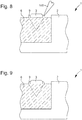
- These studs 9, visible on the Figures 6 and 7 are produced by machining, before or after drilling the housings 8. In fact, during the machining of the housings 8, material from the substrate 6 is removed so as to form these crimping elements 9.
- the closed crimping consists of a single crimping element 9 extending over the periphery of the decorative element 3.
- the baguette crimping is used to crimp the decorative elements 3 cut into a baguette.
- This crimping consists in providing crimping elements 9 extending parallel to each side of the decorative element 3 which is folded over the latter.
- the invisible crimping provision is made for the crimping elements 9 to be protruding portions arranged in the housing 8. These protruding portions cooperate with at least one groove produced on said decorative element 3 so that the crimping is carried out by inserting the decorative element 3 in the housing 8 until the projecting portions are inserted into said groove.
- the crimping step consists in placing the decorative element 3 in the housing 8 and in deforming the hooking means 5 so as to press them onto said decorative element 3. Therefore, the latter is held in the housing 8.
- the deformation hooking means 5 is done by means of a tool called beader 100 used to deform each crimping element 9, as shown in the figure 8 .
- the filling material constituting the substrate 6 is sufficiently ductile to allow deformation of the fastening means.
- An advantage of the invention is that it makes it possible to mount the decorative element in any type of material, and in particular in a hard and / or fragile material.
- the principle used is an added part principle, that is to say that a substrate made of a material capable of accepting a deformation is added in a non-plastically deformable material so as to allow mounting of a decorative element, such as than a crimp, and to give the illusion that it is this plastically non-deformable material that is crimped.
- the support material, not plastically deformable does not undergo any mechanical stress, and therefore does not risk breaking.
- the width of the cavity 4 is ideally equal to that of the decorative element 3. Consequently, the distance between the decorative element 3 and the edge of the cavity 4 should be minimized, and ideally zero, to that the filling material is not visible and give the impression that the decorative element 3 remains embedded in the support 2 in ceramic for example and not in the filling material.
- the distance between the decorative element 3 and the edge of the cavity 4 will depend on the dimensions and shapes of the decorative elements 3. For example, for a decorative element 3 with a diameter of 1 mm, the distance between the decorative element 3 and the edge of the cavity 4 will be 0.45 mm.
- the use of a composite filling material makes it possible to have a very large number of different compositions, making it possible to produce a substrate whose color is adjusted for example to the color of the decorative element or relative to the others. components of the room in which the decorative support is used.
- the use of a composite filling material makes it possible to have a very large number of different compositions making it possible to improve the affinities of the composite filling material with the support.
- the use of a composite filling material offers great flexibility in the choice of composition in order to match the chemistry of the composite filling material to that of the support.
- the basic element constituting the metal powder of the composite filling material is the same as the basic element constituting the support 2 in order to guarantee a chemical affinity between the composite filling material and the support. It is also possible to choose the composition of the composite filling material so that the latter has a coefficient of thermal expansion similar to that of the support.
- pickling agent improves the wettability of the composite filling material.
Landscapes
- Engineering & Computer Science (AREA)
- Mechanical Engineering (AREA)
- Chemical & Material Sciences (AREA)
- Manufacturing & Machinery (AREA)
- Materials Engineering (AREA)
- Inorganic Chemistry (AREA)
- Composite Materials (AREA)
- Adornments (AREA)
- Powder Metallurgy (AREA)
- Laminated Bodies (AREA)
- Cosmetics (AREA)
Priority Applications (5)
| Application Number | Priority Date | Filing Date | Title |
|---|---|---|---|
| EP15166256.6A EP3090645B1 (fr) | 2015-05-04 | 2015-05-04 | Procédé de montage d'un élément décoratif sur un support et ledit support |
| RU2016117172A RU2687342C2 (ru) | 2015-05-04 | 2016-04-29 | Способ установки декоративного элемента на основание и указанное основание |
| JP2016092302A JP6307107B2 (ja) | 2015-05-04 | 2016-05-02 | 装飾要素を支持体にマウントする方法及び支持体 |
| US15/143,766 US10405619B2 (en) | 2015-05-04 | 2016-05-02 | Method for mounting a decorative element on a support and said support |
| CN201610286372.4A CN106108296B (zh) | 2015-05-04 | 2016-05-03 | 在载体上安装装饰元件的方法和所述载体 |
Applications Claiming Priority (1)
| Application Number | Priority Date | Filing Date | Title |
|---|---|---|---|
| EP15166256.6A EP3090645B1 (fr) | 2015-05-04 | 2015-05-04 | Procédé de montage d'un élément décoratif sur un support et ledit support |
Publications (2)
| Publication Number | Publication Date |
|---|---|
| EP3090645A1 EP3090645A1 (fr) | 2016-11-09 |
| EP3090645B1 true EP3090645B1 (fr) | 2020-01-22 |
Family
ID=53180538
Family Applications (1)
| Application Number | Title | Priority Date | Filing Date |
|---|---|---|---|
| EP15166256.6A Active EP3090645B1 (fr) | 2015-05-04 | 2015-05-04 | Procédé de montage d'un élément décoratif sur un support et ledit support |
Country Status (5)
| Country | Link |
|---|---|
| US (1) | US10405619B2 (ru) |
| EP (1) | EP3090645B1 (ru) |
| JP (1) | JP6307107B2 (ru) |
| CN (1) | CN106108296B (ru) |
| RU (1) | RU2687342C2 (ru) |
Families Citing this family (13)
| Publication number | Priority date | Publication date | Assignee | Title |
|---|---|---|---|---|
| CN108393648A (zh) * | 2017-02-08 | 2018-08-14 | 通用电气公司 | 防止焊料进入孔内的塞堵材料及其方法 |
| EP3479720B1 (fr) * | 2017-11-07 | 2020-03-25 | The Swatch Group Research and Development Ltd | Procede de sertissage d'une pierre |
| EP3479721B1 (fr) * | 2017-11-07 | 2020-05-13 | The Swatch Group Research and Development Ltd | Procede de sertissage d'une pierre |
| CN108244782B (zh) * | 2018-01-26 | 2019-11-12 | 深圳市铭冠珠宝首饰有限公司 | 一种饰品珠宝镶嵌工艺 |
| EP3587626B1 (fr) * | 2018-06-28 | 2023-02-22 | Comadur S.A. | Pièce décorative réalisée par incrustation |
| WO2020095330A1 (en) * | 2018-11-11 | 2020-05-14 | Tapadia Tanvi Chandrashekhar | Alternative jewelry and manufacturing method thereof |
| CN110508970A (zh) * | 2019-07-15 | 2019-11-29 | 天津大学 | 一种三峰体系混合银焊膏及其应用 |
| USD968997S1 (en) | 2020-02-21 | 2022-11-08 | Venus by Maria Tash, Inc. | Earring |
| USD973531S1 (en) | 2020-02-27 | 2022-12-27 | Venus by Maria Tash, Inc. | Earring |
| CN112515304A (zh) * | 2020-10-20 | 2021-03-19 | 德诚珠宝集团有限公司 | 一种天然宝石粉末粘结、成形、镶嵌三合一首饰制作方法 |
| RU2756535C1 (ru) * | 2020-12-25 | 2021-10-01 | Общество с ограниченной ответственностью «ТЕХНОЛОГИИ И ДИЗАЙН» (ООО «ТЕХНОЛОГИИ И ДИЗАЙН») | Способ фиксации изделий произвольной формы для проведения бесконтактных технических операций и система фиксации изделий произвольной формы |
| RU2763180C1 (ru) * | 2021-02-04 | 2021-12-28 | Роман Владимирович Куриленко | Способ изготовления и установки декоративного или художественного аэрирующего объемного элемента в полость чаши стеклянного сосуда для питья |
| CN115894064B (zh) * | 2022-11-18 | 2023-11-14 | 大连海外华昇电子科技有限公司 | 一种低银含陶瓷金属化用amb浆料及其制备方法 |
Family Cites Families (25)
| Publication number | Priority date | Publication date | Assignee | Title |
|---|---|---|---|---|
| JP2701587B2 (ja) * | 1991-05-20 | 1998-01-21 | 三菱マテリアル株式会社 | 金属物品の製造方法 |
| JP2566174Y2 (ja) * | 1992-02-07 | 1998-03-25 | 三菱マテリアル株式会社 | ネーム入り貴金属製装身具 |
| JP3558303B2 (ja) * | 1994-08-30 | 2004-08-25 | 石福金属興業株式会社 | 白金及び白金合金用ろう材 |
| JP3274960B2 (ja) * | 1996-02-23 | 2002-04-15 | 相田化学工業株式会社 | 金属焼結品の製造方法 |
| JP2001105797A (ja) * | 1999-10-07 | 2001-04-17 | Matsuichi:Kk | 金属模様付き装飾品および当該装飾品の製造方法 |
| US6530971B1 (en) * | 2001-01-29 | 2003-03-11 | General Electric Company | Nickel-base braze material and braze repair method |
| JP2003326387A (ja) * | 2002-05-14 | 2003-11-18 | Toshiba Corp | 金属部材の補修用ろう材、補修用材料および補修方法 |
| JP2004121778A (ja) * | 2002-10-03 | 2004-04-22 | Aida Kagaku Kogyo Kk | 金属の装飾方法及び金属装飾製品 |
| JP4576335B2 (ja) * | 2003-08-02 | 2010-11-04 | 株式会社ブレイジング | ろう付用活性バインダー及び、該バインダーを用いたろう付製品の製造方法 |
| DE102004014076B3 (de) * | 2004-03-19 | 2005-12-22 | Fraunhofer-Gesellschaft zur Förderung der angewandten Forschung e.V. | Metallschaumkörper mit offenporiger Struktur sowie Verfahren zu seiner Herstellung |
| CA2630526A1 (en) * | 2004-11-30 | 2006-08-31 | The Regents Of The University Of California | Joining of dissimilar materials |
| JP5152727B2 (ja) * | 2007-12-21 | 2013-02-27 | ハリマ化成株式会社 | アルミニウムろう付け用ペースト組成物 |
| CH702836B1 (fr) * | 2008-06-23 | 2011-09-30 | Omega Sa | Pièce décorative réalisée par incrustation et pièce d'horlogerie comprenant une telle pièce. |
| CN101637838B (zh) * | 2009-08-20 | 2011-10-19 | 江西恒大高新技术股份有限公司 | 一种用渗透钎焊法制备碳化钨耐磨蚀复合涂层的方法 |
| WO2012059990A1 (ja) * | 2010-11-04 | 2012-05-10 | 相田化学工業株式会社 | 装飾金属焼結物品の製造方法および装飾金属焼結物品 |
| RU106080U1 (ru) * | 2011-03-09 | 2011-07-10 | Александр Альбертович Тормосов | Ювелирное изделие |
| JP5888483B2 (ja) * | 2011-08-30 | 2016-03-22 | 三菱マテリアル株式会社 | 銀銅合金焼結体形成用の粘土状組成物、銀銅合金焼結体形成用の粘土状組成物用粉末、銀銅合金焼結体形成用の粘土状組成物の製造方法、銀銅合金焼結体の製造方法および銀銅合金焼結体 |
| JP5959412B2 (ja) * | 2012-11-13 | 2016-08-02 | ハリマ化成株式会社 | Al−Cuろう付け用ペーストおよびAl−Cuろう付け方法 |
| CH707350A2 (fr) * | 2012-12-21 | 2014-06-30 | Omega Sa | Pièce décorative par sertissage sur métal amorphe. |
| EP2796297B1 (fr) | 2013-04-26 | 2019-01-02 | Omega SA | Pièce décorative réalisée par sertissage sur métal amorphe |
| CN105077867B (zh) * | 2012-12-21 | 2018-01-09 | 奥米加股份有限公司 | 通过镶嵌形成的装饰件 |
| CH707349B1 (fr) * | 2012-12-21 | 2017-06-30 | Omega Sa | Pièce décorative réalisée par sertissage. |
| US10772396B2 (en) * | 2012-12-21 | 2020-09-15 | Omega S.A. | Decorative piece produced by setting on amorphous metal |
| JP2014189871A (ja) * | 2013-03-28 | 2014-10-06 | Susumu Yoshida | 金属及び/又は合金の焼結体の製造方法 |
| JP6177047B2 (ja) * | 2013-08-15 | 2017-08-09 | シチズン時計株式会社 | 携帯時計 |
-
2015
- 2015-05-04 EP EP15166256.6A patent/EP3090645B1/fr active Active
-
2016
- 2016-04-29 RU RU2016117172A patent/RU2687342C2/ru not_active IP Right Cessation
- 2016-05-02 US US15/143,766 patent/US10405619B2/en active Active
- 2016-05-02 JP JP2016092302A patent/JP6307107B2/ja active Active
- 2016-05-03 CN CN201610286372.4A patent/CN106108296B/zh active Active
Non-Patent Citations (1)
| Title |
|---|
| None * |
Also Published As
| Publication number | Publication date |
|---|---|
| RU2687342C2 (ru) | 2019-05-13 |
| RU2016117172A3 (ru) | 2018-11-02 |
| JP6307107B2 (ja) | 2018-04-04 |
| CN106108296B (zh) | 2018-09-21 |
| JP2016209581A (ja) | 2016-12-15 |
| US10405619B2 (en) | 2019-09-10 |
| EP3090645A1 (fr) | 2016-11-09 |
| RU2016117172A (ru) | 2017-11-01 |
| US20160324280A1 (en) | 2016-11-10 |
| CN106108296A (zh) | 2016-11-16 |
Similar Documents
| Publication | Publication Date | Title |
|---|---|---|
| EP3090645B1 (fr) | Procédé de montage d'un élément décoratif sur un support et ledit support | |
| EP2934221B1 (fr) | Piece decorative realisee par sertissage | |
| EP2315673B1 (fr) | Pièce décorative réalisées par incrustation | |
| EP3152627B1 (fr) | Composant horloger en materiaux soudes | |
| FR2598644A1 (fr) | Produit abrasif diamante thermostable et procede de fabrication d'un tel produit | |
| EP2400354A1 (fr) | Pieds de cadran de pièce d'horlogerie | |
| EP3501326A1 (fr) | Ensemble décoratif réalisé par sertissage | |
| EP3152625B1 (fr) | Piece d'habillage d'une piece d'horlogerie en materiaux soudes | |
| WO2011064092A1 (fr) | Pièce de décoration serti invisible | |
| EP3986643A1 (fr) | Procede de fabrication additive par faisceau laser d'une piece mecanique a fonction technique et/ou decorative et piece mecanique a fonction technique et/ou decorative | |
| EP2796297A1 (fr) | Pièce décorative réalisée par sertissage sur métal amorphe | |
| EP2585877B1 (fr) | Procede de fabrication d'un composant horloger comprenant au moins deux pieces | |
| CH707351A2 (fr) | Pièce de décoration sertie invisible. | |
| CH711025B1 (fr) | Procédé de montage d'un élément décoratif sur un support et ledit support. | |
| EP2796065B1 (fr) | Pièce de décoration sertie invisible | |
| EP3587626B1 (fr) | Pièce décorative réalisée par incrustation | |
| EP2796066A1 (fr) | Piece décorative réalisée par sertissage | |
| CH707349B1 (fr) | Pièce décorative réalisée par sertissage. | |
| EP4307053A1 (fr) | Procédé de fabrication d'un composant horloger | |
| CH707350A2 (fr) | Pièce décorative par sertissage sur métal amorphe. | |
| CH719892A2 (fr) | Procédé de fabrication d'un composant horloger. | |
| CH716026B1 (fr) | Procédé de fabrication additive par faisceau laser d'une pièce mécanique à fonction technique et/ou décorative et pièce mécanique à fonction technique et/ou décorative. | |
| CH707126A2 (fr) | Procédé de solidarisation de deux pièces par brasage. | |
| CH703382B1 (fr) | Pièce de décoration à serti invisible. |
Legal Events
| Date | Code | Title | Description |
|---|---|---|---|
| PUAI | Public reference made under article 153(3) epc to a published international application that has entered the european phase |
Free format text: ORIGINAL CODE: 0009012 |
|
| AK | Designated contracting states |
Kind code of ref document: A1 Designated state(s): AL AT BE BG CH CY CZ DE DK EE ES FI FR GB GR HR HU IE IS IT LI LT LU LV MC MK MT NL NO PL PT RO RS SE SI SK SM TR |
|
| AX | Request for extension of the european patent |
Extension state: BA ME |
|
| STAA | Information on the status of an ep patent application or granted ep patent |
Free format text: STATUS: REQUEST FOR EXAMINATION WAS MADE |
|
| 17P | Request for examination filed |
Effective date: 20170509 |
|
| RBV | Designated contracting states (corrected) |
Designated state(s): AL AT BE BG CH CY CZ DE DK EE ES FI FR GB GR HR HU IE IS IT LI LT LU LV MC MK MT NL NO PL PT RO RS SE SI SK SM TR |
|
| STAA | Information on the status of an ep patent application or granted ep patent |
Free format text: STATUS: EXAMINATION IS IN PROGRESS |
|
| 17Q | First examination report despatched |
Effective date: 20171211 |
|
| REG | Reference to a national code |
Ref country code: DE Ref legal event code: R079 Ref document number: 602015045870 Country of ref document: DE Free format text: PREVIOUS MAIN CLASS: A44C0027000000 Ipc: B23K0001000000 |
|
| GRAP | Despatch of communication of intention to grant a patent |
Free format text: ORIGINAL CODE: EPIDOSNIGR1 |
|
| STAA | Information on the status of an ep patent application or granted ep patent |
Free format text: STATUS: GRANT OF PATENT IS INTENDED |
|
| RIC1 | Information provided on ipc code assigned before grant |
Ipc: B23K 1/19 20060101ALI20190719BHEP Ipc: B23K 35/36 20060101ALI20190719BHEP Ipc: A44C 27/00 20060101ALI20190719BHEP Ipc: B23K 35/26 20060101ALI20190719BHEP Ipc: B23K 35/32 20060101ALI20190719BHEP Ipc: A44C 17/04 20060101ALI20190719BHEP Ipc: B23K 35/02 20060101ALI20190719BHEP Ipc: B23K 35/28 20060101ALI20190719BHEP Ipc: B23K 1/00 20060101AFI20190719BHEP Ipc: B23K 35/30 20060101ALI20190719BHEP |
|
| INTG | Intention to grant announced |
Effective date: 20190816 |
|
| GRAS | Grant fee paid |
Free format text: ORIGINAL CODE: EPIDOSNIGR3 |
|
| GRAA | (expected) grant |
Free format text: ORIGINAL CODE: 0009210 |
|
| STAA | Information on the status of an ep patent application or granted ep patent |
Free format text: STATUS: THE PATENT HAS BEEN GRANTED |
|
| AK | Designated contracting states |
Kind code of ref document: B1 Designated state(s): AL AT BE BG CH CY CZ DE DK EE ES FI FR GB GR HR HU IE IS IT LI LT LU LV MC MK MT NL NO PL PT RO RS SE SI SK SM TR |
|
| REG | Reference to a national code |
Ref country code: GB Ref legal event code: FG4D Free format text: NOT ENGLISH |
|
| REG | Reference to a national code |
Ref country code: CH Ref legal event code: EP Ref country code: CH Ref legal event code: NV Representative=s name: ICB INGENIEURS CONSEILS EN BREVETS SA, CH |
|
| REG | Reference to a national code |
Ref country code: AT Ref legal event code: REF Ref document number: 1226613 Country of ref document: AT Kind code of ref document: T Effective date: 20200215 |
|
| REG | Reference to a national code |
Ref country code: IE Ref legal event code: FG4D Free format text: LANGUAGE OF EP DOCUMENT: FRENCH |
|
| REG | Reference to a national code |
Ref country code: DE Ref legal event code: R096 Ref document number: 602015045870 Country of ref document: DE |
|
| REG | Reference to a national code |
Ref country code: NL Ref legal event code: MP Effective date: 20200122 |
|
| REG | Reference to a national code |
Ref country code: LT Ref legal event code: MG4D |
|
| PG25 | Lapsed in a contracting state [announced via postgrant information from national office to epo] |
Ref country code: RS Free format text: LAPSE BECAUSE OF FAILURE TO SUBMIT A TRANSLATION OF THE DESCRIPTION OR TO PAY THE FEE WITHIN THE PRESCRIBED TIME-LIMIT Effective date: 20200122 Ref country code: NO Free format text: LAPSE BECAUSE OF FAILURE TO SUBMIT A TRANSLATION OF THE DESCRIPTION OR TO PAY THE FEE WITHIN THE PRESCRIBED TIME-LIMIT Effective date: 20200422 Ref country code: FI Free format text: LAPSE BECAUSE OF FAILURE TO SUBMIT A TRANSLATION OF THE DESCRIPTION OR TO PAY THE FEE WITHIN THE PRESCRIBED TIME-LIMIT Effective date: 20200122 Ref country code: PT Free format text: LAPSE BECAUSE OF FAILURE TO SUBMIT A TRANSLATION OF THE DESCRIPTION OR TO PAY THE FEE WITHIN THE PRESCRIBED TIME-LIMIT Effective date: 20200614 Ref country code: NL Free format text: LAPSE BECAUSE OF FAILURE TO SUBMIT A TRANSLATION OF THE DESCRIPTION OR TO PAY THE FEE WITHIN THE PRESCRIBED TIME-LIMIT Effective date: 20200122 |
|
| PG25 | Lapsed in a contracting state [announced via postgrant information from national office to epo] |
Ref country code: HR Free format text: LAPSE BECAUSE OF FAILURE TO SUBMIT A TRANSLATION OF THE DESCRIPTION OR TO PAY THE FEE WITHIN THE PRESCRIBED TIME-LIMIT Effective date: 20200122 Ref country code: SE Free format text: LAPSE BECAUSE OF FAILURE TO SUBMIT A TRANSLATION OF THE DESCRIPTION OR TO PAY THE FEE WITHIN THE PRESCRIBED TIME-LIMIT Effective date: 20200122 Ref country code: IS Free format text: LAPSE BECAUSE OF FAILURE TO SUBMIT A TRANSLATION OF THE DESCRIPTION OR TO PAY THE FEE WITHIN THE PRESCRIBED TIME-LIMIT Effective date: 20200522 Ref country code: LV Free format text: LAPSE BECAUSE OF FAILURE TO SUBMIT A TRANSLATION OF THE DESCRIPTION OR TO PAY THE FEE WITHIN THE PRESCRIBED TIME-LIMIT Effective date: 20200122 Ref country code: BG Free format text: LAPSE BECAUSE OF FAILURE TO SUBMIT A TRANSLATION OF THE DESCRIPTION OR TO PAY THE FEE WITHIN THE PRESCRIBED TIME-LIMIT Effective date: 20200422 Ref country code: GR Free format text: LAPSE BECAUSE OF FAILURE TO SUBMIT A TRANSLATION OF THE DESCRIPTION OR TO PAY THE FEE WITHIN THE PRESCRIBED TIME-LIMIT Effective date: 20200423 |
|
| REG | Reference to a national code |
Ref country code: DE Ref legal event code: R097 Ref document number: 602015045870 Country of ref document: DE |
|
| PG25 | Lapsed in a contracting state [announced via postgrant information from national office to epo] |
Ref country code: SK Free format text: LAPSE BECAUSE OF FAILURE TO SUBMIT A TRANSLATION OF THE DESCRIPTION OR TO PAY THE FEE WITHIN THE PRESCRIBED TIME-LIMIT Effective date: 20200122 Ref country code: RO Free format text: LAPSE BECAUSE OF FAILURE TO SUBMIT A TRANSLATION OF THE DESCRIPTION OR TO PAY THE FEE WITHIN THE PRESCRIBED TIME-LIMIT Effective date: 20200122 Ref country code: LT Free format text: LAPSE BECAUSE OF FAILURE TO SUBMIT A TRANSLATION OF THE DESCRIPTION OR TO PAY THE FEE WITHIN THE PRESCRIBED TIME-LIMIT Effective date: 20200122 Ref country code: ES Free format text: LAPSE BECAUSE OF FAILURE TO SUBMIT A TRANSLATION OF THE DESCRIPTION OR TO PAY THE FEE WITHIN THE PRESCRIBED TIME-LIMIT Effective date: 20200122 Ref country code: CZ Free format text: LAPSE BECAUSE OF FAILURE TO SUBMIT A TRANSLATION OF THE DESCRIPTION OR TO PAY THE FEE WITHIN THE PRESCRIBED TIME-LIMIT Effective date: 20200122 Ref country code: DK Free format text: LAPSE BECAUSE OF FAILURE TO SUBMIT A TRANSLATION OF THE DESCRIPTION OR TO PAY THE FEE WITHIN THE PRESCRIBED TIME-LIMIT Effective date: 20200122 Ref country code: EE Free format text: LAPSE BECAUSE OF FAILURE TO SUBMIT A TRANSLATION OF THE DESCRIPTION OR TO PAY THE FEE WITHIN THE PRESCRIBED TIME-LIMIT Effective date: 20200122 Ref country code: SM Free format text: LAPSE BECAUSE OF FAILURE TO SUBMIT A TRANSLATION OF THE DESCRIPTION OR TO PAY THE FEE WITHIN THE PRESCRIBED TIME-LIMIT Effective date: 20200122 |
|
| REG | Reference to a national code |
Ref country code: AT Ref legal event code: MK05 Ref document number: 1226613 Country of ref document: AT Kind code of ref document: T Effective date: 20200122 |
|
| PLBE | No opposition filed within time limit |
Free format text: ORIGINAL CODE: 0009261 |
|
| STAA | Information on the status of an ep patent application or granted ep patent |
Free format text: STATUS: NO OPPOSITION FILED WITHIN TIME LIMIT |
|
| 26N | No opposition filed |
Effective date: 20201023 |
|
| PG25 | Lapsed in a contracting state [announced via postgrant information from national office to epo] |
Ref country code: MC Free format text: LAPSE BECAUSE OF FAILURE TO SUBMIT A TRANSLATION OF THE DESCRIPTION OR TO PAY THE FEE WITHIN THE PRESCRIBED TIME-LIMIT Effective date: 20200122 Ref country code: AT Free format text: LAPSE BECAUSE OF FAILURE TO SUBMIT A TRANSLATION OF THE DESCRIPTION OR TO PAY THE FEE WITHIN THE PRESCRIBED TIME-LIMIT Effective date: 20200122 Ref country code: IT Free format text: LAPSE BECAUSE OF FAILURE TO SUBMIT A TRANSLATION OF THE DESCRIPTION OR TO PAY THE FEE WITHIN THE PRESCRIBED TIME-LIMIT Effective date: 20200122 |
|
| PG25 | Lapsed in a contracting state [announced via postgrant information from national office to epo] |
Ref country code: SI Free format text: LAPSE BECAUSE OF FAILURE TO SUBMIT A TRANSLATION OF THE DESCRIPTION OR TO PAY THE FEE WITHIN THE PRESCRIBED TIME-LIMIT Effective date: 20200122 Ref country code: PL Free format text: LAPSE BECAUSE OF FAILURE TO SUBMIT A TRANSLATION OF THE DESCRIPTION OR TO PAY THE FEE WITHIN THE PRESCRIBED TIME-LIMIT Effective date: 20200122 |
|
| REG | Reference to a national code |
Ref country code: BE Ref legal event code: MM Effective date: 20200531 |
|
| GBPC | Gb: european patent ceased through non-payment of renewal fee |
Effective date: 20200504 |
|
| PG25 | Lapsed in a contracting state [announced via postgrant information from national office to epo] |
Ref country code: LU Free format text: LAPSE BECAUSE OF NON-PAYMENT OF DUE FEES Effective date: 20200504 |
|
| PG25 | Lapsed in a contracting state [announced via postgrant information from national office to epo] |
Ref country code: GB Free format text: LAPSE BECAUSE OF NON-PAYMENT OF DUE FEES Effective date: 20200504 Ref country code: IE Free format text: LAPSE BECAUSE OF NON-PAYMENT OF DUE FEES Effective date: 20200504 |
|
| PG25 | Lapsed in a contracting state [announced via postgrant information from national office to epo] |
Ref country code: BE Free format text: LAPSE BECAUSE OF NON-PAYMENT OF DUE FEES Effective date: 20200531 |
|
| PG25 | Lapsed in a contracting state [announced via postgrant information from national office to epo] |
Ref country code: TR Free format text: LAPSE BECAUSE OF FAILURE TO SUBMIT A TRANSLATION OF THE DESCRIPTION OR TO PAY THE FEE WITHIN THE PRESCRIBED TIME-LIMIT Effective date: 20200122 Ref country code: MT Free format text: LAPSE BECAUSE OF FAILURE TO SUBMIT A TRANSLATION OF THE DESCRIPTION OR TO PAY THE FEE WITHIN THE PRESCRIBED TIME-LIMIT Effective date: 20200122 Ref country code: CY Free format text: LAPSE BECAUSE OF FAILURE TO SUBMIT A TRANSLATION OF THE DESCRIPTION OR TO PAY THE FEE WITHIN THE PRESCRIBED TIME-LIMIT Effective date: 20200122 |
|
| PG25 | Lapsed in a contracting state [announced via postgrant information from national office to epo] |
Ref country code: MK Free format text: LAPSE BECAUSE OF FAILURE TO SUBMIT A TRANSLATION OF THE DESCRIPTION OR TO PAY THE FEE WITHIN THE PRESCRIBED TIME-LIMIT Effective date: 20200122 Ref country code: AL Free format text: LAPSE BECAUSE OF FAILURE TO SUBMIT A TRANSLATION OF THE DESCRIPTION OR TO PAY THE FEE WITHIN THE PRESCRIBED TIME-LIMIT Effective date: 20200122 |
|
| P01 | Opt-out of the competence of the unified patent court (upc) registered |
Effective date: 20230615 |
|
| PGFP | Annual fee paid to national office [announced via postgrant information from national office to epo] |
Ref country code: FR Payment date: 20230420 Year of fee payment: 9 Ref country code: DE Payment date: 20230419 Year of fee payment: 9 Ref country code: CH Payment date: 20230602 Year of fee payment: 9 |