EP3082559B1 - Vorrichtung und verfahren zum herstellen eines länglichen hohlprofilelements - Google Patents
Vorrichtung und verfahren zum herstellen eines länglichen hohlprofilelements Download PDFInfo
- Publication number
- EP3082559B1 EP3082559B1 EP14821572.6A EP14821572A EP3082559B1 EP 3082559 B1 EP3082559 B1 EP 3082559B1 EP 14821572 A EP14821572 A EP 14821572A EP 3082559 B1 EP3082559 B1 EP 3082559B1
- Authority
- EP
- European Patent Office
- Prior art keywords
- cavity
- hollow profile
- pulling wire
- profile element
- counter
- Prior art date
- Legal status (The legal status is an assumption and is not a legal conclusion. Google has not performed a legal analysis and makes no representation as to the accuracy of the status listed.)
- Active
Links
Images


Classifications
-
- A—HUMAN NECESSITIES
- A61—MEDICAL OR VETERINARY SCIENCE; HYGIENE
- A61B—DIAGNOSIS; SURGERY; IDENTIFICATION
- A61B1/00—Instruments for performing medical examinations of the interior of cavities or tubes of the body by visual or photographical inspection, e.g. endoscopes; Illuminating arrangements therefor
- A61B1/005—Flexible endoscopes
- A61B1/0051—Flexible endoscopes with controlled bending of insertion part
- A61B1/0055—Constructional details of insertion parts, e.g. vertebral elements
-
- A—HUMAN NECESSITIES
- A61—MEDICAL OR VETERINARY SCIENCE; HYGIENE
- A61B—DIAGNOSIS; SURGERY; IDENTIFICATION
- A61B1/00—Instruments for performing medical examinations of the interior of cavities or tubes of the body by visual or photographical inspection, e.g. endoscopes; Illuminating arrangements therefor
- A61B1/00064—Constructional details of the endoscope body
- A61B1/00071—Insertion part of the endoscope body
-
- A—HUMAN NECESSITIES
- A61—MEDICAL OR VETERINARY SCIENCE; HYGIENE
- A61B—DIAGNOSIS; SURGERY; IDENTIFICATION
- A61B1/00—Instruments for performing medical examinations of the interior of cavities or tubes of the body by visual or photographical inspection, e.g. endoscopes; Illuminating arrangements therefor
- A61B1/00064—Constructional details of the endoscope body
- A61B1/0011—Manufacturing of endoscope parts
-
- A—HUMAN NECESSITIES
- A61—MEDICAL OR VETERINARY SCIENCE; HYGIENE
- A61B—DIAGNOSIS; SURGERY; IDENTIFICATION
- A61B1/00—Instruments for performing medical examinations of the interior of cavities or tubes of the body by visual or photographical inspection, e.g. endoscopes; Illuminating arrangements therefor
- A61B1/005—Flexible endoscopes
- A61B1/0051—Flexible endoscopes with controlled bending of insertion part
- A61B1/0057—Constructional details of force transmission elements, e.g. control wires
-
- B—PERFORMING OPERATIONS; TRANSPORTING
- B29—WORKING OF PLASTICS; WORKING OF SUBSTANCES IN A PLASTIC STATE IN GENERAL
- B29C—SHAPING OR JOINING OF PLASTICS; SHAPING OF MATERIAL IN A PLASTIC STATE, NOT OTHERWISE PROVIDED FOR; AFTER-TREATMENT OF THE SHAPED PRODUCTS, e.g. REPAIRING
- B29C45/00—Injection moulding, i.e. forcing the required volume of moulding material through a nozzle into a closed mould; Apparatus therefor
- B29C45/14—Injection moulding, i.e. forcing the required volume of moulding material through a nozzle into a closed mould; Apparatus therefor incorporating preformed parts or layers, e.g. injection moulding around inserts or for coating articles
- B29C45/14754—Injection moulding, i.e. forcing the required volume of moulding material through a nozzle into a closed mould; Apparatus therefor incorporating preformed parts or layers, e.g. injection moulding around inserts or for coating articles being in movable or releasable engagement with the coating, e.g. bearing assemblies
-
- B—PERFORMING OPERATIONS; TRANSPORTING
- B60—VEHICLES IN GENERAL
- B60T—VEHICLE BRAKE CONTROL SYSTEMS OR PARTS THEREOF; BRAKE CONTROL SYSTEMS OR PARTS THEREOF, IN GENERAL; ARRANGEMENT OF BRAKING ELEMENTS ON VEHICLES IN GENERAL; PORTABLE DEVICES FOR PREVENTING UNWANTED MOVEMENT OF VEHICLES; VEHICLE MODIFICATIONS TO FACILITATE COOLING OF BRAKES
- B60T11/00—Transmitting braking action from initiating means to ultimate brake actuator without power assistance or drive or where such assistance or drive is irrelevant
- B60T11/04—Transmitting braking action from initiating means to ultimate brake actuator without power assistance or drive or where such assistance or drive is irrelevant transmitting mechanically
- B60T11/046—Using cables
-
- F—MECHANICAL ENGINEERING; LIGHTING; HEATING; WEAPONS; BLASTING
- F16—ENGINEERING ELEMENTS AND UNITS; GENERAL MEASURES FOR PRODUCING AND MAINTAINING EFFECTIVE FUNCTIONING OF MACHINES OR INSTALLATIONS; THERMAL INSULATION IN GENERAL
- F16C—SHAFTS; FLEXIBLE SHAFTS; ELEMENTS OR CRANKSHAFT MECHANISMS; ROTARY BODIES OTHER THAN GEARING ELEMENTS; BEARINGS
- F16C1/00—Flexible shafts; Mechanical means for transmitting movement in a flexible sheathing
- F16C1/10—Means for transmitting linear movement in a flexible sheathing, e.g. "Bowden-mechanisms"
-
- F—MECHANICAL ENGINEERING; LIGHTING; HEATING; WEAPONS; BLASTING
- F16—ENGINEERING ELEMENTS AND UNITS; GENERAL MEASURES FOR PRODUCING AND MAINTAINING EFFECTIVE FUNCTIONING OF MACHINES OR INSTALLATIONS; THERMAL INSULATION IN GENERAL
- F16C—SHAFTS; FLEXIBLE SHAFTS; ELEMENTS OR CRANKSHAFT MECHANISMS; ROTARY BODIES OTHER THAN GEARING ELEMENTS; BEARINGS
- F16C1/00—Flexible shafts; Mechanical means for transmitting movement in a flexible sheathing
- F16C1/26—Construction of guiding-sheathings or guiding-tubes
-
- B—PERFORMING OPERATIONS; TRANSPORTING
- B29—WORKING OF PLASTICS; WORKING OF SUBSTANCES IN A PLASTIC STATE IN GENERAL
- B29K—INDEXING SCHEME ASSOCIATED WITH SUBCLASSES B29B, B29C OR B29D, RELATING TO MOULDING MATERIALS OR TO MATERIALS FOR MOULDS, REINFORCEMENTS, FILLERS OR PREFORMED PARTS, e.g. INSERTS
- B29K2021/00—Use of unspecified rubbers as moulding material
-
- B—PERFORMING OPERATIONS; TRANSPORTING
- B29—WORKING OF PLASTICS; WORKING OF SUBSTANCES IN A PLASTIC STATE IN GENERAL
- B29L—INDEXING SCHEME ASSOCIATED WITH SUBCLASS B29C, RELATING TO PARTICULAR ARTICLES
- B29L2031/00—Other particular articles
- B29L2031/753—Medical equipment; Accessories therefor
- B29L2031/7542—Catheters
-
- B—PERFORMING OPERATIONS; TRANSPORTING
- B62—LAND VEHICLES FOR TRAVELLING OTHERWISE THAN ON RAILS
- B62M—RIDER PROPULSION OF WHEELED VEHICLES OR SLEDGES; POWERED PROPULSION OF SLEDGES OR SINGLE-TRACK CYCLES; TRANSMISSIONS SPECIALLY ADAPTED FOR SUCH VEHICLES
- B62M25/00—Actuators for gearing speed-change mechanisms specially adapted for cycles
- B62M25/02—Actuators for gearing speed-change mechanisms specially adapted for cycles with mechanical transmitting systems, e.g. cables, levers
-
- F—MECHANICAL ENGINEERING; LIGHTING; HEATING; WEAPONS; BLASTING
- F16—ENGINEERING ELEMENTS AND UNITS; GENERAL MEASURES FOR PRODUCING AND MAINTAINING EFFECTIVE FUNCTIONING OF MACHINES OR INSTALLATIONS; THERMAL INSULATION IN GENERAL
- F16C—SHAFTS; FLEXIBLE SHAFTS; ELEMENTS OR CRANKSHAFT MECHANISMS; ROTARY BODIES OTHER THAN GEARING ELEMENTS; BEARINGS
- F16C2316/00—Apparatus in health or amusement
- F16C2316/10—Apparatus in health or amusement in medical appliances, e.g. in diagnosis, dentistry, instruments, prostheses, medical imaging appliances
-
- F—MECHANICAL ENGINEERING; LIGHTING; HEATING; WEAPONS; BLASTING
- F16—ENGINEERING ELEMENTS AND UNITS; GENERAL MEASURES FOR PRODUCING AND MAINTAINING EFFECTIVE FUNCTIONING OF MACHINES OR INSTALLATIONS; THERMAL INSULATION IN GENERAL
- F16C—SHAFTS; FLEXIBLE SHAFTS; ELEMENTS OR CRANKSHAFT MECHANISMS; ROTARY BODIES OTHER THAN GEARING ELEMENTS; BEARINGS
- F16C2326/00—Articles relating to transporting
- F16C2326/20—Land vehicles
-
- F—MECHANICAL ENGINEERING; LIGHTING; HEATING; WEAPONS; BLASTING
- F16—ENGINEERING ELEMENTS AND UNITS; GENERAL MEASURES FOR PRODUCING AND MAINTAINING EFFECTIVE FUNCTIONING OF MACHINES OR INSTALLATIONS; THERMAL INSULATION IN GENERAL
- F16C—SHAFTS; FLEXIBLE SHAFTS; ELEMENTS OR CRANKSHAFT MECHANISMS; ROTARY BODIES OTHER THAN GEARING ELEMENTS; BEARINGS
- F16C2326/00—Articles relating to transporting
- F16C2326/20—Land vehicles
- F16C2326/28—Bicycle propulsion, e.g. crankshaft and its support
-
- F—MECHANICAL ENGINEERING; LIGHTING; HEATING; WEAPONS; BLASTING
- F16—ENGINEERING ELEMENTS AND UNITS; GENERAL MEASURES FOR PRODUCING AND MAINTAINING EFFECTIVE FUNCTIONING OF MACHINES OR INSTALLATIONS; THERMAL INSULATION IN GENERAL
- F16D—COUPLINGS FOR TRANSMITTING ROTATION; CLUTCHES; BRAKES
- F16D2125/00—Components of actuators
- F16D2125/18—Mechanical mechanisms
- F16D2125/58—Mechanical mechanisms transmitting linear movement
- F16D2125/60—Cables or chains, e.g. Bowden cables
Definitions
- the present invention relates to an apparatus and a method for producing an elongate hollow profile element, an elongate hollow profile element and a bending unit for an endoscope.
- the present invention relates to such an elongate hollow profile element which is bendable and surrounds an inner element extending therethrough.
- Such an elongated hollow profile element finds its use, for example, as a wire guide for a bicycle brake or bicycle transmission.
- such elongated hollow profile elements are used in a bending unit for an endoscope.
- a bendable end of a catheter that is, a so-called deflecting portion as a bending unit
- a control e.g. Switzerlandseil implant actuated
- the movement of the Deflectingabiteses exactly follow the movement of the control.
- an elongate hollow profile element surrounds the inner elements of the deflecting section, such as e.g. the traction cable elements, a working channel, etc.
- the transmission of a pivoting movement of a control element to a bending movement of the deflecting section should be as accurate as possible.
- the transmission of a pivoting movement of a control element to a bending movement of the Deflectingabiteses be easy and clearly executable for the user.
- the object of the present invention is to provide an improved device and an improved method for producing an elongate hollow profile element.
- an elongated hollow profile element and a Abwinkelungshim be created for an endoscope.
- the invention thus relates to a device for producing an elongate hollow profile element comprising at least one puller wire, comprising: two abutments arranged on opposite sides of the device corresponding to the longitudinal ends of the elongated hollow profile element, one end of the at least one puller wire being anchored to the distal abutment, and a mold forming a sealed elongated cavity fillable with a thermosetting material, the cavity extending between the two abutments and the traction wire extending in the cavity so as not to contact the cavity wall.
- the counter bearings may be spaced so that the pull wire is tensioned.
- the puller wire or the puller wires can extend predefined in a straight direction between the abutments.
- At least one tube element for forming a working channel can be arranged in the device such that the ends of the at least one tube element are anchored in the counterbearings.
- the spine member may have an off-center end portion at the distal end.
- the spine member may be formed to have a proximal end portion centered with respect to the mold and cavity. on the longitudinal axis / central axis of the mold and the cavity, which may be coaxial with each other, and has a distal end portion which is eccentric relative to the mold and the cavity. does not terminate on the longitudinal axis / center axis of the mold and the cavity.
- the spine member may be angled between the proximal end portion and the distal end portion, with the angling point located on the central axis of the mold and the cavity.
- the spine member may also have a bend between the proximal end portion and the distal end portion.
- the spine element may also be angled and / or bent several times between the proximal end portion and the distal end portion.
- At least one cable element for signal transmission can be arranged in the device in the cavity in such a way that the ends of the at least one cable element are each anchored in the counter bearings.
- all puller wires, hose elements or mandrel elements and cable elements can run parallel to the longitudinal extension of the cavity.
- all puller wires may be parallel to the longitudinal extent of the cavity, and the hose members and cable members may be spirally disposed in the cavity.
- the at least one puller wire may have a coating that repels the curing material to be filled into the cavity.
- the mold may consist of a plurality of circular section-like shell-shaped parts, of which at least one has at least one access channel for the discourselende thermosetting material.
- the mold may consist of a single elongated hollow profile, the interior of which forms the cavity.
- At least one of the abutment can be a retaining cap, in which the at least one puller wire can be removably suspended, and the respective retaining cap can be supported on a die.
- the cavity may be cylindrical or polygonal in cross-section.
- the following steps are carried out: provision of a mold which can be filled with a hardening material formed sealed elongated cavity, wherein the cavity extends between two cavity sealing abutments; Inserting at least one puller wire into the mold such that at the distal abutment one end of the at least one puller wire is anchored, wherein in the cavity of the puller wire runs so that it does not touch the cavity wall; Filling the cavity with a hardening material; Curing the hardening material; and opening the mold.
- the at least one puller wire can be pulled in such a way that the puller wire comes loose from the hardened material surrounding it and forms a movement channel for the puller wire.
- the hardening material may be an elastomer.
- FIG. 1 shows an application example of an elongated hollow profile element according to the invention, wherein Fig. 1A a side view shows Fig. 1B a sectional view along AA in Fig. 1A shows and Fig. 1C a perspective view shows.
- the present invention is applied to a jacket member of a bend unit (also called a deflecting portion) for an endoscope.
- the jacket element here is an elongated hollow profile element in the context of the invention.
- Such a bending unit is based on the FIGS. 1 and 2 explained in more detail below.
- the bending unit has at the distal end an endoscope head 11, in which, for example, a camera (not shown) and LEDs (not shown) are arranged.
- an elongated hollow profile element 100 is arranged on the proximal side of the endoscope head 11, in the interior of which a plurality of tension cables 13 run in the longitudinal direction of the elongate hollow profile element 100.
- a plurality of tension cables 13 run in the longitudinal direction of the elongate hollow profile element 100.
- traction ropes 13 provided in the elongated hollow profile element 100 four traction ropes 13 provided. It can also be provided three, five or more pull ropes 13.
- an intermediate piece 12 is arranged, which serves the anchoring of cable spiral wrap 20, in which the traction cables 13 run proximally from the intermediate piece 12.
- the intermediate piece 12 is constructed as a ring element.
- a catheter tube 21 is arranged, which leads to an endoscope operating part.
- the catheter tube 21 surrounds the cable spiral wrap 20, in which the traction cables 13 slidably run.
- the endoscope head 11 has a working channel 16 and at least one flushing channel 17.
- the endoscope head 11 has a flushing channel 17.
- the endoscope head 11 may also have a plurality of flushing channels. More specifically, the working channel 16 and the flushing channel 17 are provided in the endoscope head 11 in the axial direction parallel to the central axis of the endoscope head 11. As in Fig. 1B and Fig. 1C shown, the flushing channel 17 is disposed radially outside of the working channel 16, wherein the invention is not limited thereto.
- the endoscope head 11 has respective recesses for traction cable anchoring body 15 on its outer peripheral surface.
- traction cable anchoring body 15 may have various shapes and may be a barrel nipple, a nipple, a ball nipple, etc.
- the Switzerlandseilverank fürstechnik 15 is a barrel nipple.
- Each of the indentations is sized to accommodate a traction cable anchoring body 15 and has on its proximal side a supporting surface area on which the traction cable anchoring body 15 can be supported in the proximal direction. The support surface area thus extends horizontally, i. parallel to the proximal end surface of the endoscope head 11.
- the axial through openings for the traction cables 13 are in the elongated hollow profile element 100 - viewed perpendicular to the axis of the elongate hollow profile element 100 - arranged on an imaginary circle, which is spaced closer to the outer periphery than to the inner periphery of the elongated hollow profile element 100.
- the traction cables 13 are thus guided protected between the intermediate piece 12 and the endoscope head 11 in the elongated hollow profile element 100.
- four axial through openings for four traction cables 13 are provided in the elongated hollow profile element 100. In the respective axial through opening for the traction cables 13, the corresponding traction cable 13 can be pulled axially relative to the surrounding axial through hole.
- the elongated hollow profile element 100 has in the present example, an axially extending parallel to the working channel 16 and the four axial through holes extending for the tension cables 13 continuous channel as a flushing passage 17.
- the flushing channel in the elongated hollow profile element 100 is between the working channel 16 and the imaginary circle, where the axial through openings are arranged for the tension cables 13, provided in the elongated hollow profile element 100.
- the intermediate piece 12 has an axial central inner opening through which the working channel passes.
- the pressure-stable hose member 14 is arranged for working channel in the inner opening of the intermediate piece 12.
- the endoscope head 11 can be pivoted by means of a pulling movement on the tension cables 13 by a control not shown in any direction in a known manner. As shown in the drawing, in this case the right pull rope 13 has been pulled more strongly than the front and the rear pull rope in the proximal direction, so that the endoscope head 11 inclines to the right and the left pull rope 13 anchored to it in the distal direction draws.
- FIG. 3 shows a perspective view of the application example of Fig. 1 , wherein the elongated hollow profile element according to the invention is shown separately.
- FIG. 3 shows the first embodiment, in which the bending unit without the elongated hollow profile element and the elongated hollow profile element 100 are shown separately.
- the elongated hollow profile element 100 is not shown in the installed position for the sake of clarity.
- the representation of the bending unit corresponds to the representation of Fig. 1C , wherein the interior is shown in the region of the elongate hollow profile element 100.
- a cable 22 for the camera is shown.
- the cable 22 is similar to the flushing channel 17 axially in the elongated hollow profile element 100 parallel to the working channel 16 and the four axial through holes for the traction cables 13.
- the cable 22 has a flat rectangular in cross-sectional shape, to which the channel 118 in elongated hollow profile element 100 is adapted.
- the channel 118 in the elongate hollow profile element 100 is between the working channel 16 and the imaginary circle, where the axial continuous Openings are arranged for the traction cables 13, provided in the elongated hollow profile element 100.
- the bending unit is kept in a state of being completely assembled except for the elongated hollow profile member 100.
- the bending unit in a state is hereinafter referred to as a raw angle unit.
- a mold which in the present example consists of two half-molds 2a and 2b, has inside a cylindrical extension as the counter-mold for the outer periphery of the elongated hollow profile element 100.
- the outer diameter of the endoscope head 11, the elongated hollow profile element 100 and the intermediate piece 12 are equal, and the inner diameter of the cylindrical extension is adapted to this outer diameter of the endoscope head 11, the elongated hollow profile element 100 and the intermediate piece 12.
- the half-molds 2a and 2b are slidable toward and away from each other. When they are pushed together, the cavity 3 is closed at the periphery.
- the endoscope head 11 and the intermediate piece 12 of the bending unit respectively form abutments which clamp the tension cables 13 running therein and between which the elongated hollow profile element 100 is to be produced.
- the endoscope head 11 forms a first abutment and the intermediate piece 12 forms a second abutment.
- Each abutment is a holding cap, which ensures that the traction cables 13 can be kept taut.
- the hose member 14 forms a portion of the working channel 16 on its inner circumferential surface.
- the distal end portion of the working channel 16 is formed in the endoscope head 11 without the hose member 14 as a hole in the endoscope head 11.
- the tube member 14 may extend to the distal end side of the endoscope head 11.
- the hose element 14 in the region between endoscope head 11 and intermediate piece 12 can be dispensed with.
- the hose member 14 may end in the intermediate piece 12.
- the construction can be chosen so that the working channel 16 is formed only by a mandrel element 4.
- the mandrel element 4 corresponds to the stabilizing body 4 Fig. 4A ,
- the diameter of the mandrel element 4 is adapted to the trainee end diameter of the working channel.
- the mold consists of a plurality of in cross-section each having a semicircle forming mold parts 2a and 2b, which are pushed towards each other, wherein in the collapsed state, the entire interior of the moldings forms the cavity 3.
- the mold may also consist of three or more in cross section in each case a circular segment forming moldings which are pushed towards each other, wherein in the collapsed state, the entire interior of the moldings forms the cavity 3.
- the mold consists of a single elongated hollow profile whose interior forms the cavity 3.
- the mold if it consists of a plurality of circular section-like shell moldings, at least one molding having an access channel for the Swiss bachelorde curing material.
- the mandrel element 4 extends perpendicularly from the die 1, which virtually forms a cover of the mold 2a, 2b.
- the mandrel element 4 lies on the central axis of the mold 2a, 2b.
- a straight working channel 16 is formed which runs centrically in the bending unit.
- the spine member 4 may have a proximal end portion extending on the central axis of the mold 2a, 2b and a distal end portion extending at an angle to the central axis of the mold 2a, 2b and off-center to the central axis of the mold 2a, 2b the die 1 is attached.
- the mandrel element 4 can thus be angled between the proximal end portion and the distal end portion, wherein the angle of deflection point on the central axis of the mold 2a, 2b and the cavity 3 is located.
- the mandrel member 4 may also have a radius of curvature between the proximal end portion and the distal end portion.
- the spine element 4 may even be angled and / or bent several times between the proximal end portion and the distal end portion or may be serpentine. Since the elastomer material is elastic even after curing, extraction of the mandrel element 4 from the formed and cured elongated hollow profile element 100 is possible without problems, even if the mandrel element 4 is angled, bent or serpentine.
- a working channel 16 can be created which does not terminate centrically but eccentrically at the distal end on the distal surface of the endoscope head 11 at the distal end.
- the mold element 5 for the flushing channel 17 can also be angled, bent or serpentine as needed.
Landscapes
- Health & Medical Sciences (AREA)
- Engineering & Computer Science (AREA)
- Life Sciences & Earth Sciences (AREA)
- Surgery (AREA)
- Mechanical Engineering (AREA)
- General Engineering & Computer Science (AREA)
- Molecular Biology (AREA)
- Biomedical Technology (AREA)
- Veterinary Medicine (AREA)
- Biophysics (AREA)
- Nuclear Medicine, Radiotherapy & Molecular Imaging (AREA)
- Optics & Photonics (AREA)
- Pathology (AREA)
- Radiology & Medical Imaging (AREA)
- Public Health (AREA)
- Physics & Mathematics (AREA)
- Heart & Thoracic Surgery (AREA)
- Medical Informatics (AREA)
- General Health & Medical Sciences (AREA)
- Animal Behavior & Ethology (AREA)
- Manufacturing & Machinery (AREA)
- Oral & Maxillofacial Surgery (AREA)
- Transportation (AREA)
- Endoscopes (AREA)
- Instruments For Viewing The Inside Of Hollow Bodies (AREA)
Description
- Die vorliegende Erfindung betrifft eine Vorrichtung und ein Verfahren zum Herstellen eines länglichen Hohlprofilelements, ein längliches Hohlprofilelement und eine Abwinkelungseinheit für ein Endoskop. Insbesondere betrifft die vorliegende Erfindung ein solches längliches Hohlprofilelement, das biegbar ist und ein sich durch dieses erstreckendes Innenelement umgibt.
- Ein solches längliches Hohlprofilelement findet seinen Einsatz beispielsweise als Drahtführung für eine Fahrradbremse oder Fahrradgangschaltung. Darüber hinaus werden solche länglichen Hohlprofilelemente in einer Abwinkelungseinheit für ein Endoskop angewendet.
- Bei einem Endoskop wird nämlich ein biegbares Ende eines Katheters, das heißt ein sogenannter Deflectingabschnitt als Abwinkelungseinheit, durch Schwenken eines Steuerelementes bewegt, das z.B. Zugseilelemente betätigt, die mit dem Kopf des Deflectingabschnittes verbunden sind. Dadurch soll die Bewegung des Deflectingabschnittes genau der Bewegung des Steuerelementes folgen. In diesem Deflectingabschnitt umgibt ein längliches Hohlprofilelement die Innenelemente des Deflectingabschnittes, wie z.B. die Zugseilelemente, einen Arbeitskanal, etc.
- Bei medizinischen Untersuchungen mit einem Endoskop sollte die Übertragung einer Schwenkbewegung eines Steuerelementes zu einer Biegebewegung des Deflectingabschnittes möglichst genau sein. Andererseits sollte die Übertragung einer Schwenkbewegung eines Steuerelementes zu einer Biegebewegung des Deflectingabschnittes für den Anwender einfach und übersichtlich ausführbar sein.
- Aufgabe der vorliegenden Erfindung ist es, eine verbesserte Vorrichtung und ein verbessertes Verfahren zum Herstellen eines länglichen Hohlprofilelements zu schaffen. Ausserdem sollen ein längliches Hohlprofilelement und eine Abwinkelungseinheit für ein Endoskop geschaffen werden.
- In Hinblick auf die Vorrichtung ist diese Aufgabe erfindungsgemäß durch eine Vorrichtung mit den Merkmalen von Anspruch 1 gelöst.
- In Hinblick auf das Verfahren ist diese Aufgabe erfindungsgemäß durch ein Verfahren mit den Merkmalen von Anspruch 15 gelöst.
- Vorteilhafte Weiterbildungen sind Gegenstand der abhängigen Ansprüche.
- Die Erfindung betrifft somit eine Vorrichtung zum Herstellen eines länglichen Hohlprofilelements, das zumindest einen Zugdraht aufweist, mit: zwei an entgegengesetzten Seiten der Vorrichtung angeordneten Gegenlagern, die den Längsenden des länglichen Hohlprofilelements entsprechen, wobei am distalen Gegenlager ein Ende des zumindest einen Zugdrahtes verankert ist, und einer Form, die einen mit einem aushärtenden Material befüllbaren abgedichteten länglichen Hohlraum ausbildet, wobei der Hohlraum sich zwischen den beiden Gegenlagern erstreckt und im Hohlraum der Zugdraht so verläuft, dass er die Hohlraumwand nicht berührt.
- In der Vorrichtung können die Gegenlager so beabstandet sein, dass der Zugdraht gespannt ist. Dadurch können der Zugdraht oder die Zugdrähte sich vordefiniert in gerader Richtung zwischen den Gegenlagern erstrecken. Nach dem Aushärten des einzufüllenden Materials sind somit Zugdrahtkanäle vorhanden, die gerade verlaufen. In den Zugdrahtkanälen sind bereits die Zugdrähte angeordnet.
- In der Vorrichtung kann außer dem zumindest einen Zugdraht im Hohlraum zumindest ein Schlauchelement zur Ausbildung eines Arbeitskanals so angeordnet sein, dass die Enden des zumindest einen Schlauchelementes jeweils in den Gegenlagern verankert sind.
- Alternativ kann in der Vorrichtung außer dem zumindest einen Zugdraht im Hohlraum zumindest ein entnehmbares Dornelement zur Ausbildung eines Arbeitskanals so angeordnet sein, dass die Enden des zumindest einen Dornelementes jeweils in den Gegenlagern sitzen.
- In der Vorrichtung kann das Dornelement am distalen Ende einen aussermittigen Endabschnitt aufweisen. Das Dornelement kann also so ausgebildet sein, dass es einen proximalen Endabschnitt, der in bezug auf die Form und den Hohlraum mittig d.h. auf der Längsachse/Mittelachse der Form und des Hohlraums, die zueinander koaxial sein können, ist, und einen distalen Endabschnitt hat, der in bezug auf die Form und den Hohlraum aussermittig d.h. nicht auf der Längsachse/Mittelachse der Form und des Hohlraums endet. Das Dornelement kann also zwischen dem proximalen Endabschnitt und dem distalen Endabschnitt abgewinkelt sein, wobei sich der Abwinkelungspunkt auf der Mittelachse der Form und des Hohlraums befindet. Das Dornelement kann zwischen dem proximalen Endabschnitt und dem distalen Endabschnitt auch eine Biegung aufweisen. Das Dornelement kann zwischen dem proximalen Endabschnitt und dem distalen Endabschnitt auch mehrfach abgewinkelt und/oder gebogen sein.
- In der Vorrichtung kann des weiteren im Hohlraum zumindest ein Kabelelement zur Signalübertragung so angeordnet sein, dass die Enden des zumindest einen Kabelelementes jeweils in den Gegenlagern verankert sind.
- In der Vorrichtung können sämtliche Zugdrähte, Schlauchelemente oder Dornelemente und Kabelelemente parallel zu der Längserstreckung des Hohlraums verlaufen.
- In der Vorrichtung können sämtliche Zugdrähte parallel zu der Längserstreckung des Hohlraums verlaufen, und die Schlauchelemente und Kabelelemente spiralartig im Hohlraum angeordnet sein.
- In der Vorrichtung kann der zumindest eine Zugdraht eine Beschichtung aufweisen, die das in den Hohlraum einzufüllende aushärtende Material abstößt.
- In der Vorrichtung kann die Form aus mehreren im Querschnitt jeweils ein Kreissegment bildenden Formteilen bestehen, die zueinander schiebbar sind, wobei im zusammengeschobenen Zustand der gesamte Innenraum der Formteile den Hohlraum ausbildet.
- In der Vorrichtung kann die Form aus mehreren kreisabschnittartigen Schalen-Formteilen bestehen, von denen mindestens einer mindestens einen Zugangskanal für das einzufüllende aushärtende Material aufweist.
- In der Vorrichtung kann die Form aus einem einzigen länglichen Hohlprofil bestehen, dessen Innenraum den Hohlraum ausbildet.
- Zumindest eines der Gegenlager kann eine Haltekappe sein, in der der zumindest eine Zugdraht entnehmbar einhängbar ist, und die jeweilige Haltekappe kann an einer Matritze gestützt sein.
- In der Vorrichtung kann der Hohlraum im Querschnitt zylindrisch oder polygonal sein.
- Im erfindungsgemäßen Verfahren zum Herstellen eines länglichen Hohlprofilelements, das zumindest einen Zugdraht aufweist, werden folgende Schritte ausgeführt: Bereitstellen einer Form, die einen mit einem aushärtenden Material befüllbaren abgedichteten länglichen Hohlraum ausbildet, wobei der Hohlraum sich zwischen zwei den Hohlraum abdichtenden Gegenlagern erstreckt; Einlegen zumindest einen Zugdrahtes in die Form derart, dass am distalen Gegenlager ein Ende des zumindest einen Zugdrahtes verankert ist, wobei im Hohlraum der Zugdraht so verläuft, dass er die Hohlraumwand nicht berührt; Befüllen des Hohlraums mit einem aushärtenden Material; Aushärten des aushärtenden Materials; und Öffnen der Form.
- Im Verfahren kann nach dem Öffnen der Form der zumindest einen Zugdraht derart gezogen werden, dass sich der Zugdraht von dem ihn umgebenden ausgehärteten Material löst und sich ein Bewegungskanal für den Zugdraht bildet. Das aushärtende Material kann ein Elastomer sein.
- Das Elastomer kann Silikon, ein Naturkautschuk oder ein Silikonkautschuk sein. Das längliche Hohlprofilelement kann eine Abwinkelungseinheit für ein Endoskop sein.
- Die Merkmale der Erfindung können geeignet kombiniert werden.
- Nachstehend ist die Erfindung detailliert anhand von Beispielen erläutert.
-
-
Figur 1 zeigt ein Anwendungsbeispiel eines erfindungsgemäßen länglichen Hohlprofilelements, wobeiFig. 1A eine Seitenansicht zeigt,Fig. 1B eine Schnittansicht zeigt undFig. 1C eine perspektivische Ansicht zeigt. -
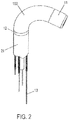
Figur 2 zeigt eine perspektivische Ansicht des Anwendungsbeispiels vonFig. 1 in gebogenem Zustand. -
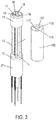
Figur 3 zeigt eine perspektivische Ansicht des Anwendungsbeispiels vonFig. 1 , wobei das erfindungsgemäße längliche Hohlprofilelement separat gezeigt ist. -
Figur 4 zeigt eine Vorrichtung zum Herstellen des erfindungsgemäßen länglichen Hohlprofilelements, wobeiFig. 1A eine perspektivische Explosionsdarstellung zeigt,Fig. 4B eine perspektivische Ansicht zeigt,Fig. 4C eine Seitenansicht zeigt undFig. 4D eine Schnittansicht zeigt. - Nachstehend sind Ausführungsbeispiele der vorliegenden Erfindung beschrieben.
- Zunächst ist unter Bezugnahme auf die Zeichnungen ein erstes Ausführungsbeispiel erläutert.
-
Figur 1 zeigt ein Anwendungsbeispiel eines erfindungsgemäßen länglichen Hohlprofilelements, wobeiFig. 1A eine Seitenansicht zeigt,Fig. 1B eine Schnittansicht entlang A-A inFig. 1A zeigt undFig. 1C eine perspektivische Ansicht zeigt. - Im ersten Ausführungsbeispiel ist die vorliegende Erfindung bei einem Mantelelement einer Abwinkelungseinheit (auch Deflectingabschnitt genannt) für ein Endoskop angewendet. Das Mantelelement ist hierbei ein längliches Hohlprofilelement im Sinne der Erfindung.
- Eine solche Abwinkelungseinheit ist anhand der
Figuren 1 und2 nachstehend genauer erläutert. - Die Abwinkelungseinheit hat am distalen Ende einen Endoskopkopf 11, in welchem beispielsweise eine nicht gezeigte Kamera und nicht gezeigte LED's angeordnet sind. In proximaler Richtung der Abwinkelungseinheit ist an der proximalen Seite des Endoskopkopfes 11 ein längliches Hohlprofilelement 100 angeordnet, in dessen Inneren mehrere Zugseile 13 in Längsrichtung des länglichen Hohlprofilelements 100 laufen. Im vorliegenden Beispiel sind im länglichen Hohlprofilelement 100 vier Zugseile 13 vorgesehen. Es können auch drei, fünf oder mehr Zugseile 13 vorgesehen sein.
- An der proximalen Seite des länglichen Hohlprofilelementes 100 ist ein Zwischenstück 12 angeordnet, das der Verankerung von Seilzug-Spiralhüllen 20 dient, in denen die Zugseile 13 proximal vom Zwischenstück 12 laufen. Das Zwischenstück 12 ist als ein Ringelement aufgebaut.
- An der proximalen Seite des Zwischenstücks 12 ist ein Katheterschlauch 21 angeordnet, der zu einem Endoskopbedienteil führt. Der Katheterschlauch 21 umgibt die Seilzug-Spiralhüllen 20, in denen die Zugseile 13 verschiebbar laufen.
- Die Abwinkelungseinheit erstreckt sich somit von dem Ringelement 12 an der proximalen Seite der Abwinkelungseinheit zu dem Endoskopkopf 11 an der distalen Seite der Abwinkelungseinheit.
- Nachstehend sind die Elemente der Abwinkelungseinheit detaillierter erläutert.
- Der Endoskopkopf 11 kann ein Kunststoffträger aus einem organischen polymeren Material sein, der z.B. durch Spritzgießen herstellbar ist. Beispielsweise besteht der Endoskopkopf 11 aus einem Thermoplast oder einem Duroplast. Insbesondere kann der Endoskopkopf 11 aus Polypropylen (PP), Acrylnitryl-Butadienstyrol (ABS), Polycarbonat (PC), Polyethylenterephtalat (PET), Polybutylenterephtalat (PBT), Polyamid (PA), Polyphenylensulfid (PPS), Polysulfon (PSU), Polyethersulfon (PES), Polyetherimid (PEI), etc hergestellt werden. Diese Angaben sind lediglich Beispiele und weitere Materialen können für den Endoskopkopf 11 verwendet werden.
- An der distalen Stirnfläche besitzt der Endoskopkopf 11 distale Öffnungen 19 - 19. Diese Öffnungen können insbesondere eine distale Öffnung eines Arbeitskanals 16, eine distale Öffnung eines Spülkanals 17, ein Kamerafenster 18 und ein oder mehrere LED-Fenster 19 sein. Das Kamerafenster 18 dient einer Signaleingabe für eine nicht gezeigte Kamera und das LED-Fenster 19 dient einer Signalausgabe für einen nicht gezeigten LED-Chip.
- Somit weist der Endoskopkopf 11 einen Arbeitskanal 16 und zumindest einen Spülkanal 17 auf. Im vorliegenden Beispiel weist der Endoskopkopf 11 einen Spülkanal 17 auf. Der Endoskopkopf 11 kann aber auch mehrere Spülkanäle haben. Genauer gesagt sind der Arbeitskanal 16 und der Spülkanal 17 im Endoskopkopf 11 in axialer Richtung parallel zur Mittelachse des Endoskopkopfes 11 vorgesehen. Wie in
Fig. 1B und Fig. 1C gezeigt, ist der Spülkanal 17 radial außerhalb des Arbeitskanals 16 angeordnet, wobei die Erfindung nicht darauf beschränkt ist. - Beabstandet zur proximalen Endfläche besitzt der Endoskopkopf 11 an seiner Außenumfangsfläche jeweilige Einbauchungen für Zugseilverankerungskörper 15. Ein solcher Zugseilverankerungskörper 15 kann verschiedene Formen haben und kann ein Tonnennippel, ein Birnennippel, ein Kugelnippel etc. sein. Im vorliegenden Beispiel ist der Zugseilverankerungskörper 15 ein Tonnennippel. Jede der Einbauchungen hat eine derartige Größe, dass ein Zugseilverankerungskörper 15 darin Platz findet, und besitzt an ihrer proximalen Seite einen Abstützflächenbereich, an dem sich der Zugseilverankerungskörper 15 in proximaler Richtung abstützen kann. Der Abstützflächenbereich erstreckt sich somit horizontal d.h. parallel zur proximalen Endfläche des Endoskopkopfes 11. Die Einbauchungen sind an die Form des Zugseilverankerungskörpers 15 angepasst und sind im vorliegenden Beispiel zylinderartig gestaltet. Somit hat im vorliegenden Beispiel der Endoskopkopf 11 vier solche Abstützflächenbereiche. Jeder Abstützflächenbereich ist zentrisch mit einer zur proximalen Endfläche des Endoskopkopfes 11 laufenden rinnenartigen Einkerbung versehen, die bei am Abstützflächenbereich eingesetzten Zugseilverankerungskörper 15 das mit dem Zugseilverankerungskörper 15 verbundene Zugseil 13 aufnimmt. Der Durchmesser des Abstützflächenbereiches ist auf jeden Fall größer als der Durchmesser des Zugseils 13. Sollte z.B. ein quaderartiger Zugseilverankerungskörper angewendet werden und die Einbauchung daher eine quaderartige Form haben, ergibt sich ein viereckiger Abstützflächenbereich.
- In jede seitliche Einbauchung am Endoskopkopf 11 ist ein Zugseilverankerungskörper 15 so eingesetzt, dass seine proximalen Seite am Abstützflächenbereich anliegt, so dass eine in proximaler Richtung wirkende Zugkraft vom Zugseilverankerungskörper 15 auf den Abstützflächenbereich und somit auf den Endoskopkopf 11 übertragen wird. Jeder Zugseilverankerungskörper 15 ist am distalen Ende eines Zugseils 13 in bekannter Weise fest angeordnet.
- Im Endoskopkopf 11 verläuft entlang seiner Längsachse der Arbeitskanal 16 von der proximalen zu der distalen Richtung. An der proximalen Seite des Endoskopkopf 11 besitzt der Endoskopkopf 11 eine Durchmessererweiterung am Eingang für den Arbeitskanal 16. In diese Durchmessererweiterung ist ein Schlauchelement 14 eingesetzt. Das Schlauchelement 14 bildet an seiner Innenumfangsfläche einen Abschnitt des Arbeitskanals 16 aus, wie dies in
Fig. 1B gezeigt ist. Das Schlauchelement 14 kann in den Endoskopkopf 11 eingeklebt oder eingepresst sein oder anderweitig befestigt sein. - Das erfindungsgemäße längliche Hohlprofilelement 100 ist ein schlauchartiges Gebilde, das den Arbeitskanal 16 radial umgibt. Im vorliegenden Beispiel ist umgibt das längliche Hohlprofilelement 100 den Arbeitskanal 16 so, dass das Schlauchelement 14 zwischen dem Arbeitskanal 16 und dem länglichen Hohlprofilelement 100 angeordnet ist. In einer Alternative kann das Schlauchelement 14 auch weggelassen werden. Dann bildet das längliche Hohlprofilelement 100 an der Innenumfangsseite somit den Arbeitskanal 16 direkt aus. Das längliche Hohlprofilelement 100 besteht aus einem Elastomer. Insbesondere kann Silikon, ein Naturkautschuk oder ein Silikonkautschuk etc. für das längliche Hohlprofilelement 100 verwendet werden.
- An der distalen Seite liegt das längliche Hohlprofilelement 100 dicht am Endoskopkopf 11 an. An der proximalen Seite liegt das längliche Hohlprofilelement 100 dicht am Zwischenstück 12 an. Entlang seiner Längserstreckung sind im Inneren des länglichen Hohlprofilelements 100 parallel zur Längsachse des länglichen Hohlprofilelements 100 die Zugseile 13 angeordnet. Im länglichen Hohlprofilelement 100 sind daher zwischen dem Innenumfang und dem Außenumfang axiale durchgehende Öffnungen erfindungsgemäß geschaffen, in denen die Zugseile 13 laufen. Die axialen durchgehenden Öffnungen für die Zugseile 13 sind im länglichen Hohlprofilelement 100 - unter Betrachtung senkrecht zur Achse des länglichen Hohlprofilelements 100 - auf einem gedachten Kreis angeordnet, der näher zum Außenumfang als zum Innenumfang des länglichen Hohlprofilelements 100 beabstandet ist. Die Zugseile 13 sind somit zwischen dem Zwischenstück 12 und dem Endoskopkopf 11 im länglichen Hohlprofilelement 100 geschützt geführt. Im vorliegenden Beispiel sind vier axiale durchgehende Öffnungen für vier Zugseile 13 im länglichen Hohlprofilelement 100 vorgesehen. In der jeweiligen axialen durchgehenden Öffnung für die Zugseile 13 kann das entsprechende Zugseil 13 relativ zu der es umgebenden axialen durchgehenden Öffnung axial gezogen werden.
- Das längliche Hohlprofilelement 100 besitzt im vorliegenden Beispiel einen sich axial erstreckenden parallel zu dem Arbeitskanal 16 und den vier axialen durchgehenden Öffnungen für die Zugseile 13 verlaufenden durchgehenden Kanal als Spülkanal 17. Der Spülkanal im länglichen Hohlprofilelement 100 ist zwischen dem Arbeitskanal 16 und dem gedachten Kreis, an dem die axialen durchgehenden Öffnungen für die Zugseile 13 angeordnet sind, im länglichen Hohlprofilelement 100 vorgesehen.
- Das Zwischenstück 12 hat an der proximalen Seite Sacklöcher für die Verankerung der Seilzug-Spiralhüllen 20. Im Zwischenstück 12 sind die Seilzug-Spiralhüllen 20 von der proximalen Seite des Zwischenstücks 12 aus eingeführt. Vorzugsweise sind die Seilzug-Spiralhüllen 20 fest mit dem Zwischenstück 12 verbunden. Sie können z.B. eingeklebt sein. Der Durchmesser der Sacklöcher im Zwischenstück 12 kann auch so gewählt werden, dass die Seilzug-Spiralhüllen 20 darin eingepresst werden.
- Das Zwischenstück 12 besitzt eine axiale zentrische Innenöffnung, durch die der Arbeitskanal läuft. Im vorliegenden Beispiel ist daher in der Innenöffnung des Zwischenstücks 12 das druckstabile Schlauchelement 14 für Arbeitskanal angeordnet.
- Die zentrische Innenöffnung für das Schlauchelement 14 und eine seitliche Durchgangsöffnung für den Spülkanal 17 sind im Zwischenstück 12 in axialer Richtung parallel zur Mittelachse des Zwischenstücks 12 vorgesehen. Wie in
Fig. 1B gezeigt, ist die seitliche Durchgangsöffnung für den Spülkanal 17 radial außerhalb der zentrischen Innenöffnung angeordnet. Die Anordnung der seitlichen Durchgangsöffnung für den Spülkanal 17 und der zentrischen Innenöffnung für das Schlauchelement 14 des Arbeitskanals 16 entsprechen der Anordnung des Spülkanal 17 und des Arbeitskanals 16 im Endoskopkopf 11. -
Figur 2 zeigt eine perspektivische Ansicht des Anwendungsbeispiels vonFig. 1 in gebogenem Zustand. - Der Endoskopkopf 11 kann anhand einer Zugbewegung an den Zugseilen 13 durch ein nicht gezeigtes Steuerelement in eine beliebige Richtung in bekannter Weise geschwenkt werden. Wie dies in der Zeichnung gezeigt ist, ist hierbei das rechte Zugseil 13 stärker als das vordere und das hintere Zugseil in die proximale Richtung gezogen worden, so dass der Endoskopkopf 11 sich nach rechts neigt und das an ihm verankerte linke Zugseil 13 in die distale Richtung zieht.
-
Figur 3 zeigt eine perspektivische Ansicht des Anwendungsbeispiels vonFig. 1 , wobei das erfindungsgemäße längliche Hohlprofilelement separat gezeigt ist. - Insbesondere zeigt
Fig. 3 das erste Ausführungsbeispiel, bei dem die Abwinkelungseinheit ohne das längliche Hohlprofilelement und das längliche Hohlprofilelement 100 separat gezeigt sind. Anders ausgedrückt ist das längliche Hohlprofilelement 100 der besseren Übersichtlichkeit wegen nicht in Einbaulage gezeigt. - Die Darstellung der Abwinkelungseinheit entspricht der Darstellung von
Fig. 1C , wobei das Innere im Bereich des länglichen Hohlprofilelements 100 gezeigt ist. Insbesondere ist auch ein Kabel 22 für die Kamera gezeigt. Das Kabel 22 verläuft ähnlich wie der Spülkanal 17 axial im länglichen Hohlprofilelement 100 parallel zu dem Arbeitskanal 16 und den vier axialen durchgehenden Öffnungen für die Zugseile 13. Im vorliegenden Beispiel hat das Kabel 22 eine flache im Querschnitt rechteckige Form, an die der Kanal 118 im länglichen Hohlprofilelement 100 angepasst ist. Der Kanal 118 im länglichen Hohlprofilelement 100 ist zwischen dem Arbeitskanal 16 und dem gedachten Kreis, an dem die axialen durchgehenden Öffnungen für die Zugseile 13 angeordnet sind, im länglichen Hohlprofilelement 100 vorgesehen. - Das das längliche Hohlprofilelement 100 weist an der proximalen und distalen Seite (nur die distale Seite ist in
Fig. 3 erkennbar) vier Öffnungen 113 für die Zugseile 13, eine Öffnung 117 für den Spülkanal 17, eine Öffnung 118 für das Kabel 22 der Kamera und eine Öffnung 118 für den Arbeitskanal 18 auf. - Nachstehend ist die Herstellung des länglichen Hohlprofilelements 100 beschrieben.
-
Figur 4 zeigt eine Vorrichtung zum Herstellen des erfindungsgemäßen länglichen Hohlprofilelements, wobeiFig. 1A eine perspektivische Explosionsdarstellung zeigt,Fig. 4B eine perspektivische Ansicht zeigt,Fig. 4C eine Seitenansicht zeigt undFig. 4D eine Schnittansicht zeigt. - Die Abwinkelungseinheit wird in einem Zustand, bei dem sie mit Ausnahme des länglichen Hohlprofilelements 100 fertig montiert ist, bereitgehalten. Die Abwinkelungseinheit in einem Zustand ist nachstehend als Rohabwinkelungseinheit bezeichnet.
- Eine Form, die im vorliegenden Beispiel aus zwei Halbformen 2a und 2b besteht, besitzt im Inneren eine zylindrische Erstreckung als die Gegenform für den Außenumfang des länglichen Hohlprofilelements 100. Der Außendurchmesser des Endoskopkopfes 11, des länglichen Hohlprofilelementes 100 und des Zwischenstücks 12 sind gleich, und der Innendurchmesser der zylindrischen Erstreckung ist an diesen Außendurchmesser des Endoskopkopfes 11, des länglichen Hohlprofilelementes 100 und des Zwischenstücks 12 angepasst.
- Die Halbformen 2a und 2b sind im Querschnitt jeweils halbkreisartig und bilden zusammen einen Hohlzylinder, dessen Innenraum einen Hohlraum 3 für die Herstellung des länglichen Hohlprofilelementes 100 ausbildet. Der Hohlraum 3 ist zylinderartig. Seine Innenform ist an die Außenform des länglichen Hohlprofilelementes 100 angepasst.
- Die Halbformen 2a und 2b sind zueinander hin und voneinander weg schiebbar. Wenn sie zusammengeschoben sind, ist der Hohlraum 3 am Umfang geschlossen.
- Anders ausgedrückt, besteht die Form aus mehreren im Querschnitt jeweils einen Halbkreis bildenden Formteilen 2a und 2b, die zueinander schiebbar sind, wobei im zusammengeschobenen Zustand der gesamte Innenraum der Formteile den Hohlraum 3 ausbildet.
- In den Hohlraum 3 wird die Abwinkelungseinheit in dem Zustand, bei dem sie mit Ausnahme des länglichen Hohlprofilelements 100 fertig montiert ist d.h. die Rohabwinkelungseinheit, so eingelegt, dass die distale Stirnfläche des Endoskopkopfes 11 an der distalen Stirnfläche der Formteile 2a und 2b fluchtet, wie dies in
Fig. 4D erkennbar ist. In dem im Hohlraum 3 eingelegten Zustand bilden der Endoskopkopf 11 und das Zwischenstück 12 der Abwinkelungseinheit jeweils Gegenlager, die die darin laufenden Zugseile 13 spannen und zwischen denen das längliche Hohlprofilelement 100 hergestellt werden soll. Der Endoskopkopf 11 bildet ein erstes Gegenlager und das Zwischenstück 12 bildet ein zweites Gegenlager. Jedes Gegenlager stellt eine Haltekappe dar, die dafür sorgt, dass die Zugseile 13 gespannt gehalten werden können. - In dem Bereich des Hohlraums 3 der Formteile 2a und 2b, im eingelegten Zustand des Endoskopkopfes 11 und des Zwischenstückes 12 sich zwischen dem Endoskopkopf 11 und dem Zwischenstück 12 erstreckt, ist in jedem Formteil 2a und 2b eine radiale Öffnung so vorgesehen, dass sie radial die Wand des Formteils 2a und 2b durchdringt. An der Außenseite des Formteils 2a und 2b setzt sich die Öffnung zu einem Zugangsrohr fort. Die Öffnung und das Zugangsrohr bilden jeweils ein Zugangskanalelement 6 zur Befüllung des Hohlraums 3 mit dem einzufüllenden aushärtenden Material für das längliche Hohlprofilelement 100. Im vorliegenden Beispiel befindet sich das Zugangskanalelement 6 des Formteils 2a weiter an der distalen Seite und das Zugangskanalelement 6 des Formteils 2b befindet sich weiter an der proximalen Seite.
- An die distale Stirnfläche des Endoskopkopfes 11 und an die distale Stirnfläche der Formteile 2a und 2b wird eine scheibenartige Matrize 1 gesetzt. Die scheibenartige Matrize 1 besitzt an ihrer proximalen Seite einen Stabilisierungskörper 4 für das Schlauchelement 14 für den Arbeitskanal und ein Formelement 5 für den Spülkanal. Der einen Stabilisierungskörper 4 und das Formelement 5 erstrecken sich senkrecht zur scheibenartigen Matrize 1. Genauer gesagt ist der Stabilisierungskörper 4 auf der Mittelachse der scheibenartigen Matrize 1 angeordnet und das Formelement 5 ist benachbart und parallel zum Stabilisierungskörper 4 angeordnet. Die Lage zwischen Stabilisierungskörper 4 und Formelement 5 ist so gewählt, dass das Formelement 5 den Spülkanal ausbildet, während der Stabilisierungskörper 4 den Arbeitskanal ausbildet oder das Schlauchelement 14 zur Ausbildung des Arbeitskanals von innen stützt.
- Wenn die Formhälften 2a und 2b bei eingelegter Rohabwinkelungseinheit geschlossen sind, wird die scheibenartige Matrize 1 von der distalen Seite her auf die distalen Stirnflächen der Formhälften 2a und 2b so aufgeschoben, dass der Stabilisierungskörper 4 in das Schlauchelement 14 einfährt, wie dies den
Figuren 4A bis 4D entnehmbar ist. Somit ist die Form geschlossen. In diesem Zustand verläuft im Hohlraum 3 der Zugdraht 13 so, dass er die Hohlraumwand nicht berührt. - Nun wird das das längliche Hohlprofilelement 100 ausbildende Elastomermaterial in die Form eingegossen. Insbesondere wird das Elastomermaterial durch eines der beiden Zugangskanalelemente 6 eingegossen, während das Zugangskanalelement 6 als Luftabgabeöffnung dient, durch die die im Hohlraum 3 befindliche durch das eingegossene Elastomermaterial verdrängte Luft entweichen kann. Wenn der Innenraum der Form mit Elastomermaterial gefüllt, z.B. wenn das Elastomermaterial aus dem als Luftabgabeöffnung dienenden Zugangskanalelement 6 austritt oder wenn ein Sensor am innen befindlichen Eingang des als Luftabgabeöffnung dienenden Zugangskanalelement 6 ein Vorhandensein von Elastomermaterial anzeigt, werden die Zugangskanalelemente 6 geschlossen.
- Das Elastomermaterial härtet aus. Daraufhin wird die Form geöffnet und die Abwinkelungseinheit wird entnommen. Am Außenumfang des länglichen Hohlprofilelements 100 noch vorhandenes Elastomermaterial, das dem Innenraum der Zugangskanalelemente 6 entspricht, wird abgeschnitten. Alternativ kann an jeder Form 2a, 2b am Innenumfang des Hohlraums 3 am Mündungsbereich der Zugangskanalelemente 6 zum Hohlraum 3 ein Schieber angeordnet sein, der nach Einfüllen des Elastomermaterial das jeweilige Zugangskanalelement 6 versperrt.
- Nach dem Öffnen der Form 2a, 2b werden die Zugseile 13 derart gezogen, dass sich die Zugseile 13 von dem sie umgebenden Elastomermaterial lösen. Dadurch bildet sich ein Bewegungskanal für die Zugseile 13. Vorzugsweise sind die Zugseile 13 mit einer Beschichtung versehen, die das Elastomermaterial absto-ßen.
- Somit wird eine Abwinkelungseinheit erzeugt, die ein längliches Hohlprofilelement 100 hat, in welchem Zugseile 13 geführt werden und ein Arbeitskanal verläuft. Das längliche Hohlprofilelement 100 ist ein Mantelelement der Abwinkelungseinheit.
- Im ersten Beispiel sind eine Kamera und LED-Elemente im Endoskopkopf 11 angeordnet. Alternativ kann anstelle der LED-Elemente eine Ultraschallemittiereinrichtung angeordnet sein, und anstelle der Kamera kann ein Akustiksensor angeordnet sein.
- Im ersten Beispiel bildet das Schlauchelement 14 an seiner Innenumfangsfläche einen Abschnitt des Arbeitskanals 16 aus. Der distale Endabschnitt des Arbeitskanals 16 ist dabei im Endoskopkopf 11 ohne das Schlauchelement 14 als Loch im Endoskopkopf 11 ausgebildet. Alternativ kann das Schlauchelement 14 sich bis zu der distalen Endseite des Endoskopkopfes 11 erstrecken.
- In einer anderen Alternative kann auf das Schlauchelement 14 in dem Bereich zwischen Endoskopkopf 11 und Zwischenstück 12 verzichtet werden. In diesem Fall kann das Schlauchelement 14 im Zwischenstück 12 enden.
- In diesem Fall kann die Konstruktion so gewählt werden, dass der Arbeitskanal 16 nur durch ein Dornelement 4 gebildet wird. Das Dornelement 4 entspricht dem Stabilisierungskörper 4 aus
Fig. 4A . Der Durchmesser des Dornelements 4 ist an den auszubildenden Enddurchmesser des Arbeitskanals angepasst. - Die Anordnung der Kanäle im Endoskopkopf 11 ist nicht einschränkend und kann je nach Bedarf abgewandelt werden.
- Im Beispiel von
Fig. 4 besteht die Form aus mehreren im Querschnitt jeweils einen Halbkreis bildenden Formteilen 2a und 2b, die zueinander schiebbar sind, wobei im zusammengeschobenen Zustand der gesamte Innenraum der Formteile den Hohlraum 3 ausbildet. Die Form kann auch aus drei oder mehr im Querschnitt jeweils ein Kreissegment bildenden Formteilen bestehen, die zueinander schiebbar sind, wobei im zusammengeschobenen Zustand der gesamte Innenraum der Formteile den Hohlraum 3 ausbildet. In einer weiteren Alternative besteht die Form aus einem einzigen länglichen Hohlprofil, dessen Innenraum den Hohlraum 3 ausbildet. - Nicht jedes Formteil muss einen Zugangskanal besitzen. Es ist ausreichend, dass die Form, wenn sie aus mehreren kreisabschnittartigen Schalen-Formteilen besteht, mindestens ein Formteil mit einem Zugangskanal für das einzufüllende aushärtende Material aufweist.
- Im ersten Beispiel erstreckt sich das Dornelement 4 senkrecht von der Matritze 1, die quasi einen Deckel der Form 2a, 2b bildet. Somit liegt im ersten Beispiel das Dornelement 4 auf der Mittelachse der Form 2a, 2b. Dadurch wird ein gerader Arbeitskanal 16 ausgebildet, der in der Abwinkelungseinheit zentrisch verläuft. Alternativ kann das Dornelement 4 einen proximalen Endabschnitt, der sich auf der Mittelachse der Form 2a, 2b erstreckt, und einen distalen Endabschnitt haben, der unter einem Winkel zur der Mittelachse der Form 2a, 2b verläuft und aussermittig zur Mittelachse der Form 2a, 2b an der Matritze 1 befestigt ist.
- Das Dornelement 4 kann somit zwischen dem proximalen Endabschnitt und dem distalen Endabschnitt abgewinkelt sein, wobei sich der Abwinkelungspunkt auf der Mittelachse der Form 2a, 2b und des Hohlraums 3 befindet. Das Dornelement 4 kann zwischen dem proximalen Endabschnitt und dem distalen Endabschnitt auch eine Biegung mit einem Radius aufweisen. Das Dornelement 4 kann sogar zwischen dem proximalen Endabschnitt und dem distalen Endabschnitt mehrfach abgewinkelt und/oder gebogen sein oder schlangenlinienförmig verlaufen. Da das Elastomermaterial auch nach dem Aushärten elastisch ist, ist ein Herausziehen des Dornelementes 4 aus dem ausgebildeten und ausgehärteten länglichen Hohlprofilelement 100 ohne Probleme möglich, selbst wenn das Dornelement 4 abgewinkelt, gebogen oder schlangenlinienförmig ist. Dadurch kann ein Arbeitskanal 16 geschaffen werden, der am distalen Ende nicht zentrisch sondern aussermittig an der distalen Fläche des Endoskopkopfes 11 endet. Dadurch steht für eine Kamera und ein Kamerafenster 18 mehr Platz zu Verfügung, die näher zur Mitte hin als im ersten Beispiel angeordnet werden können.
- In ähnlicher Weise kann auch das Formelement 5 für den Spülkanal 17 bei Bedarf abgewinkelt, gebogen oder schlangenlinienförmig sein.
-
- 1
- Matrize
- 2a, 2b
- Formkörper
- 3
- Hohlraum
- 4
- Stabilisierungskörper; Dornelement
- 5
- Formelement für Spülkanal
- 6
- Zugangskanalelement
- 11
- Endoskopkopf; erstes Gegenlager
- 12
- Zwischenstück; zweites Gegenlager
- 13
- Zugseil
- 14
- Schlauchelement für Arbeitskanal
- 15
- Zugseilverankerungskörper
- 16
- Arbeitskanal
- 17
- Spülkanal
- 18
- Kamerafenster
- 19
- LED-Fenster
- 20
- Spiralhülle für Zugseil
- 21
- Katheterschlauch
- 22
- Kabel für Kamera
- 100
- längliches Hohlprofilelement
- 113
- Öffnungen für die Zugseile 13
- 117
- Öffnung für Spülkanal 17
- 118
- Öffnung für Kabel 22
- 119
- Öffnung für den Arbeitskanal 16
Claims (18)
- Vorrichtung zum Herstellen eines länglichen Hohlprofilelements (100) mit zumindest einer axialen Öffnung, in der ein Zugdraht (13) axial relativ zum Hohlprofilelement (100) ziehbar angeordnet ist, wobei der Zugdraht (13) zur Übertragung einer Schwenkbewegung eines Steuerelements zu einer Abwinkelungseinheit dient, mit:zwei an entgegengesetzten Seiten der Vorrichtung angeordneten Gegenlagern (11, 12), die den Längsenden des länglichen Hohlprofilelements entsprechen, wobei am distalen Gegenlager (11) ein Ende des zumindest einen Zugdrahtes (13) verankert ist, undeiner Form (2a, 2b), die einen mit einem aushärtenden Material, das das Hohlprofilelement (100) ausbildet, befüllbaren abgedichteten länglichen Hohlraum (3) ausbildet, wobei der Hohlraum (3) sich zwischen den beiden Gegenlagern (11, 12) erstreckt und im Hohlraum (3) der Zugdraht (13) so verläuft, dass er die Hohlraumwand nicht berührt,wobei in die Form (2a, 2b) die beiden Gegenlager (11, 12) eingelegt sind, undwobei am Ende der Herstellung der zumindest eine Zugdraht (13) im ausgehärteten Material axial relativ zum Hohlprofilelement (100) ziehbar angeordnet bleibt.
- Vorrichtung gemäß Anspruch 1, wobei
die Gegenlager (11, 12) so beabstandet sind, dass der Zugdraht (13) gespannt ist. - Vorrichtung gemäß einem der Ansprüche 1 oder 2, wobei
außer dem zumindest einen Zugdraht (13) im Hohlraum (3) zumindest ein Schlauchelement (14) zur Ausbildung eines Arbeitskanals so angeordnet ist, dass die Enden des zumindest einen Schlauchelementes (14) jeweils in den Gegenlagern (11, 12) verankert sind. - Vorrichtung gemäß einem der Ansprüche 1 oder 2, wobei
außer dem zumindest einen Zugdraht (13) im Hohlraum (3) zumindest ein entnehmbares Dornelement (4) zur Ausbildung eines Arbeitskanals so angeordnet ist, dass die Enden des zumindest einen Dornelementes jeweils in den Gegenlagern sitzen. - Vorrichtung gemäß Anspruch 4, wobei
das Dornelement (4) am distalen Ende einen außermittigen Endabschnitt aufweist. - Vorrichtung gemäß einem der Ansprüche 1 bis 5, wobei
des Weiteren im Hohlraum (3) zumindest ein Kabelelement zur Signalübertragung so angeordnet ist, dass die Enden des zumindest einen Kabelelementes jeweils in den Gegenlagern (11, 12) verankert sind. - Vorrichtung gemäß einem der Ansprüche 1 bis 6, wobei
sämtliche Zugdrähte (13), Schlauchelemente (14) oder Dornelemente (4) und Kabelelemente parallel zu der Längserstreckung des Hohlraums (3) verlaufen. - Vorrichtung gemäß einem der Ansprüche 1 bis 6, wobei
sämtliche Zugdrähte (13) und die Schlauchelemente parallel zu der Längserstreckung des Hohlraums (3) verlaufen, und Kabelelemente spiralartig im Hohlraum (3) angeordnet sind. - Vorrichtung gemäß einem der Ansprüche 1 bis 8, wobei
der zumindest eine Zugdraht (13) eine Beschichtung aufweist, die das in den Hohlraum (3) einzufüllende aushärtende Material abstößt. - Vorrichtung gemäß einem der Ansprüche 1 bis 9, wobei
die Form aus mehreren im Querschnitt jeweils ein Kreissegment bildenden Formteilen (2a, 2b) besteht, die zueinander schiebbar sind, wobei im zusammengeschobenen Zustand der gesamte Innenraum der Formteile (2a, 2b) den Hohlraum (3) ausbildet. - Vorrichtung gemäß Anspruch 10, wobei
die Form aus mehreren kreisabschnittartigen Schalen-Formteilen (2a, 2b) besteht, von denen mindestens einer mindestens einen Zugangskanal (6) für das einzufüllende aushärtende Material aufweist. - Vorrichtung gemäß einem der Ansprüche 1 bis 9, wobei
die Form aus einem einzigen länglichen Hohlprofil besteht, dessen Innenraum den Hohlraum (3) ausbildet. - Vorrichtung gemäß einem der Ansprüche 1 bis 12, wobeizumindest eines des Gegenlager (11) eine Haltekappe ist, in der der zumindest eine Zugdraht (13) entnehmbar einhängbar ist, unddie jeweilige Haltekappe an einer Matritze gestützt ist.
- Vorrichtung gemäß einem der Ansprüche 1 bis 13, wobei
der Hohlraum (3) im Querschnitt zylindrisch oder polygonal ist. - Verfahren zum Herstellen eines länglichen Hohlprofilelements mit zumindest einer axialen Öffnung, in die ein Zugdraht (13) axial relativ zum Hohlprofilelement (100) ziehbar angeordnet ist, wobei der Zugdraht (13) zur Übertragung einer Schwenkbewegung eines Steuerelements zu einer Abwinkelungseinheit dient, mit den folgenden Schritten:Bereitstellen einer Form (2a, 2b), die einen mit einem aushärtenden Material befüllbaren abgedichteten länglichen Hohlraum (3) ausbildet, wobei der Hohlraum (3) sich zwischen zwei den Hohlraum (3) abdichtenden Gegenlagern (11, 12) erstreckt;Einlegen der beiden Gegenlager (11, 12) mit zumindest einem Zugdraht (13) in die Form (2a, 2b) derart, dass am distalen Gegenlager (11) ein Ende des zumindest einen Zugdrahtes (13) verankert ist, wobei im Hohlraum (3) der Zugdraht (13) so verläuft, dass er die Hohlraumwand nicht berührt;Befüllen des Hohlraums (3) mit einem aushärtenden Material zur Ausbildung des Hohlprofilelements (100);Aushärten des aushärtenden Materials; undÖffnen der Form (2a, 2b),wobei am Ende des Herstellverfahrens der zumindest ein Zugdraht (13) im ausgehärteten Material axial relativ zum Hohlprofilelement (100) ziehbar angeordnet bleibt.
- Verfahren gemäß Anspruch 15, mit dem folgenden Schritt:
nach dem Öffnen der Form (2a, 2b):
Ziehen des zumindest einen Zugdrahtes (13) derart, dass sich der Zugdraht (13) von dem ihn umgebenden ausgehärteten Material löst und sich ein Bewegungskanal für den Zugdraht (13) bildet. - Verfahren gemäß einem der Ansprüche 15 oder 16, wobei das aushärtende Material ein Elastomer ist.
- Verfahren gemäß Anspruch 17, wobei
das Elastomer Silikon, ein Naturkautschuk oder ein Silikonkautschuk ist.
Applications Claiming Priority (2)
| Application Number | Priority Date | Filing Date | Title |
|---|---|---|---|
| DE102013226591.3A DE102013226591A1 (de) | 2013-12-19 | 2013-12-19 | Vorrichtung und verfahren zum herstellen eines länglichen hohlprofilelements, längliches hohlprofilelement und eine abwinkelungseinheit für ein endoskop |
| PCT/EP2014/077938 WO2015091464A1 (de) | 2013-12-19 | 2014-12-16 | Vorrichtung und verfahren zum herstellen eines länglichen hohlprofilelements, längliches hohlprofilelement und eine abwinkelungseinheit für ein endoskop |
Publications (2)
| Publication Number | Publication Date |
|---|---|
| EP3082559A1 EP3082559A1 (de) | 2016-10-26 |
| EP3082559B1 true EP3082559B1 (de) | 2019-07-17 |
Family
ID=52278596
Family Applications (1)
| Application Number | Title | Priority Date | Filing Date |
|---|---|---|---|
| EP14821572.6A Active EP3082559B1 (de) | 2013-12-19 | 2014-12-16 | Vorrichtung und verfahren zum herstellen eines länglichen hohlprofilelements |
Country Status (6)
| Country | Link |
|---|---|
| US (1) | US9955856B2 (de) |
| EP (1) | EP3082559B1 (de) |
| JP (1) | JP6471166B2 (de) |
| CN (1) | CN106455905B (de) |
| DE (1) | DE102013226591A1 (de) |
| WO (1) | WO2015091464A1 (de) |
Families Citing this family (15)
| Publication number | Priority date | Publication date | Assignee | Title |
|---|---|---|---|---|
| DE202015100712U1 (de) * | 2015-02-13 | 2016-05-17 | Ipek International Gmbh | Ablenkeinrichtung für Inspektionssysteme |
| GB201516884D0 (en) * | 2015-09-23 | 2015-11-04 | Racine Marc André | Reinforced corrugated plastic sheets and products |
| US11267217B2 (en) * | 2016-08-23 | 2022-03-08 | Marc-Andre Racine | System and method for bending a hollow core sheet using rods |
| DE102016124553A1 (de) * | 2016-12-15 | 2018-06-21 | Karl Storz Se & Co. Kg | Endoskop |
| EP4218531B1 (de) * | 2018-11-02 | 2026-02-18 | Boston Scientific Medical Device Limited | Vorrichtungen und systeme für eine biopsiekappe und gehäuse |
| KR20220143818A (ko) * | 2019-12-19 | 2022-10-25 | 노아 메디컬 코퍼레이션 | 모듈식 내시경용의 시스템 및 방법 |
| CN111300459B (zh) * | 2020-03-13 | 2022-10-25 | 哈尔滨工业大学 | 一种多自由度仿人刚柔混合手及其制造工艺 |
| DE102020111889A1 (de) | 2020-04-30 | 2021-11-04 | Ambu A/S | Endoskop mit verbesserter Lenkdrahtanordnung |
| DE102021109022A1 (de) | 2021-04-12 | 2022-10-13 | Karl Storz Se & Co. Kg | Schaft für ein flexibles Endoskop oder für ein flexibles endoskopisches Instrument |
| DE102021109865A1 (de) * | 2021-04-19 | 2022-10-20 | Karl Storz Se & Co. Kg | Verfahren zum Ergänzen eines Bauteils eines medizinischen Instruments |
| WO2022268891A1 (en) | 2021-06-22 | 2022-12-29 | Ambu A/S | Endoscope with a three-wire steering mechanism |
| CN118234423A (zh) * | 2021-06-28 | 2024-06-21 | 格朗皮创新公司 | 进入装置 |
| CN116141575B (zh) * | 2023-04-19 | 2023-09-19 | 西安感崆电子信息科技有限公司 | 一种线束传感器注塑模具及其制造方法 |
| TWI862143B (zh) * | 2023-09-05 | 2024-11-11 | 晉弘科技股份有限公司 | 用於製造整合型內視鏡探頭的模具與整合型內視鏡探頭及其製造方法 |
| CN117261108A (zh) * | 2023-10-31 | 2023-12-22 | 湖南省华芯医疗器械有限公司 | 一种弯曲组件的制造方法、过渡组件及内窥镜 |
Family Cites Families (83)
| Publication number | Priority date | Publication date | Assignee | Title |
|---|---|---|---|---|
| JPS4827116Y1 (de) * | 1967-04-21 | 1973-08-09 | ||
| US3549806A (en) | 1967-05-05 | 1970-12-22 | Gen Electric | Fundamental pitch frequency signal extraction system for complex signals |
| US3605725A (en) | 1968-08-07 | 1971-09-20 | Medi Tech Inc | Controlled motion devices |
| DE6905185U (de) * | 1969-02-11 | 1972-04-06 | Bowden Controls Ltd | Bowdenzug. |
| JPS5329167Y2 (de) * | 1973-03-03 | 1978-07-21 | ||
| JPS6121041Y2 (de) | 1977-08-04 | 1986-06-24 | ||
| JPS5939128B2 (ja) | 1979-10-31 | 1984-09-21 | オリンパス光学工業株式会社 | 内視鏡 |
| JPS57110228A (en) | 1980-12-26 | 1982-07-09 | Olympus Optical Co | Air and water sending switch apparatus of endoscope |
| JPS57190546A (en) * | 1981-05-18 | 1982-11-24 | Olympus Optical Co | Production of hard endoscope |
| US4415767A (en) | 1981-10-19 | 1983-11-15 | Votan | Method and apparatus for speech recognition and reproduction |
| JPS60148536A (ja) | 1984-01-17 | 1985-08-05 | オリンパス光学工業株式会社 | 内視鏡 |
| JPS61118713A (ja) | 1984-11-14 | 1986-06-06 | Olympus Optical Co Ltd | 内視鏡 |
| US4670009A (en) * | 1985-04-16 | 1987-06-02 | American Hospital Supply Corp. | Backform inserts for catheter |
| JPS62227312A (ja) | 1986-03-27 | 1987-10-06 | 旭光学工業株式会社 | 内視鏡の湾曲操作ワイヤの取付構造 |
| JPH0219129A (ja) * | 1988-07-08 | 1990-01-23 | Toshiba Corp | 内視鏡装置 |
| JPH0520701U (ja) * | 1991-09-03 | 1993-03-19 | 住友電気工業株式会社 | 内視鏡 |
| US5245133A (en) * | 1991-10-15 | 1993-09-14 | Thomas & Betts Corporation | Moisture-resistant cable splice and sealing structure thereof |
| JP3219521B2 (ja) * | 1993-03-01 | 2001-10-15 | オリンパス光学工業株式会社 | 内視鏡 |
| US5569157A (en) | 1993-05-07 | 1996-10-29 | Olympus Optical Co., Ltd. | Endoscope |
| US5588950A (en) | 1994-07-11 | 1996-12-31 | Asahi Kogaku Kogyo Kabushiki Kaisha | Portable endoscope system |
| US5630419A (en) | 1994-12-20 | 1997-05-20 | Tetrad Corporation | Sealing connector for multiconductor cables |
| DE19627016C1 (de) | 1996-07-04 | 1998-02-12 | Etm Endotech Gmbh Medizintechn | Flexibles Endoskop |
| US5845241A (en) | 1996-09-04 | 1998-12-01 | Hughes Electronics Corporation | High-accuracy, low-distortion time-frequency analysis of signals using rotated-window spectrograms |
| JPH10225439A (ja) | 1997-02-17 | 1998-08-25 | Olympus Optical Co Ltd | 内視鏡用撮像装置 |
| DE19731965A1 (de) | 1997-07-24 | 1999-01-28 | Etm Endotech Gmbh Medizintechn | Luft/Wasser- und Absaugventile an Endoskopen |
| DE19840986A1 (de) | 1998-09-08 | 2000-03-09 | Etm Endoskopische Technik Gmbh | Schnellverschluss für ein Endoskop |
| DE19843337A1 (de) * | 1998-09-22 | 2000-03-23 | Sram De Gmbh | Justiereinrichtung für Betätigungszüge zum Steuern von Fahrradgetrieben |
| US6734893B1 (en) | 1998-12-04 | 2004-05-11 | Olympus Winter & Ibe Gmbh | Endoscopy illumination system for stroboscopy |
| JP3179426B2 (ja) | 1998-12-21 | 2001-06-25 | オリンパス光学工業株式会社 | 内視鏡装置 |
| US6547722B1 (en) | 1999-07-13 | 2003-04-15 | Olympus Optical Co., Ltd. | Endoscope having resistance to high-temperature and high-pressure steam |
| JP2001061772A (ja) | 1999-08-30 | 2001-03-13 | Fuji Photo Optical Co Ltd | 内視鏡の流体制御装置 |
| JP3488170B2 (ja) | 2000-03-21 | 2004-01-19 | オリンパス株式会社 | 内視鏡 |
| JP3821206B2 (ja) | 2000-09-29 | 2006-09-13 | フジノン株式会社 | 内視鏡のコネクタ用防水キャップ |
| JP2002160691A (ja) * | 2000-11-28 | 2002-06-04 | Nissin Kogyo Co Ltd | バーハンドル車両用ブレーキ装置 |
| JP2002238831A (ja) | 2001-02-16 | 2002-08-27 | Fuji Photo Optical Co Ltd | 内視鏡 |
| JP2002291699A (ja) | 2001-03-30 | 2002-10-08 | Asahi Optical Co Ltd | 声帯観察用の内視鏡システム |
| US20060199999A1 (en) * | 2001-06-29 | 2006-09-07 | Intuitive Surgical Inc. | Cardiac tissue ablation instrument with flexible wrist |
| US6793622B2 (en) | 2001-09-05 | 2004-09-21 | Olympus Optical Co., Ltd. | Electric bending endoscope |
| JP2003190085A (ja) | 2001-12-25 | 2003-07-08 | Olympus Optical Co Ltd | 電気的コネクタ |
| JP2007111541A (ja) | 2002-05-29 | 2007-05-10 | Olympus Corp | 内視鏡装置と内視鏡用接続装置 |
| JP2004049891A (ja) | 2002-05-29 | 2004-02-19 | Olympus Corp | 内視鏡装置 |
| US7179223B2 (en) | 2002-08-06 | 2007-02-20 | Olympus Optical Co., Ltd. | Endoscope apparatus having an internal channel |
| DE10320228A1 (de) * | 2003-05-05 | 2004-11-25 | Stm Medizintechnik Starnberg Gmbh | Endoskopschaft |
| US7842028B2 (en) | 2005-04-14 | 2010-11-30 | Cambridge Endoscopic Devices, Inc. | Surgical instrument guide device |
| JP4461100B2 (ja) | 2004-02-16 | 2010-05-12 | オリンパス株式会社 | 内視鏡システム |
| AU2005228956B2 (en) | 2004-03-23 | 2011-08-18 | Boston Scientific Limited | In-vivo visualization system |
| JP2005304586A (ja) | 2004-04-19 | 2005-11-04 | Pentax Corp | 側方視型内視鏡の先端部 |
| JP4661190B2 (ja) | 2004-11-30 | 2011-03-30 | 富士フイルム株式会社 | 洗浄アダプタ |
| CN2762381Y (zh) | 2004-12-17 | 2006-03-01 | 亮泰企业股份有限公司 | 交流电源插头及插座的防水结构 |
| US20060252993A1 (en) | 2005-03-23 | 2006-11-09 | Freed David I | Medical devices and systems |
| EP1886617A4 (de) | 2005-05-26 | 2010-09-29 | Ars Co Ltd | Endoskopvorrichtung |
| WO2007002526A1 (en) | 2005-06-24 | 2007-01-04 | Everest Vit, Inc. | Insertion tube storage carousel |
| DE102005041454A1 (de) | 2005-08-31 | 2007-03-01 | Karl Storz Gmbh & Co. Kg | Endoskop |
| US20070225562A1 (en) | 2006-03-23 | 2007-09-27 | Ethicon Endo-Surgery, Inc. | Articulating endoscopic accessory channel |
| AU2007201204B2 (en) | 2006-03-23 | 2012-07-12 | Ethicon Endo-Surgery, Inc. | Articulating endoscopic accessory channel |
| JP4812515B2 (ja) | 2006-05-26 | 2011-11-09 | 富士フイルム株式会社 | 洗浄アダプタ |
| US7615067B2 (en) | 2006-06-05 | 2009-11-10 | Cambridge Endoscopic Devices, Inc. | Surgical instrument |
| JP2008119057A (ja) | 2006-11-08 | 2008-05-29 | Matsushita Electric Works Ltd | カプセル型撮像装置 |
| KR200444134Y1 (ko) | 2007-07-09 | 2009-04-10 | 유메디칼 주식회사 | 음성신호를 이용한 후두 스트로보스코프 |
| ES2356497T3 (es) | 2007-08-23 | 2011-04-08 | Tyco Healthcare Group Lp | Dispositivos quirúrgicos endoscópicos. |
| US9005238B2 (en) | 2007-08-23 | 2015-04-14 | Covidien Lp | Endoscopic surgical devices |
| JP2009201762A (ja) | 2008-02-28 | 2009-09-10 | Hoya Corp | 内視鏡および撮影モジュール |
| EP2119390B1 (de) | 2008-05-16 | 2011-07-20 | FUJIFILM Corporation | Anschlussstück für Endoskop |
| CN102307510B (zh) * | 2008-12-10 | 2014-10-08 | 阿姆布股份有限公司 | 具有照相机壳体的内窥镜及制造照相机壳体的方法 |
| US8700129B2 (en) | 2008-12-31 | 2014-04-15 | St. Jude Medical, Atrial Fibrillation Division, Inc. | Devices and methods for catheter localization |
| DE102009060500B4 (de) | 2009-12-22 | 2015-12-17 | Xion Gmbh | Verfahren zur stroboskopischen Untersuchung sich wiederholender Vorgänge und Anordnung zum Betreiben dieses Verfahrens |
| WO2011108157A1 (ja) | 2010-03-05 | 2011-09-09 | オリンパスメディカルシステムズ株式会社 | 内視鏡 |
| CN102791182A (zh) | 2010-03-16 | 2012-11-21 | 奥林巴斯医疗株式会社 | 连接器座、连接器连接系统、光源装置和内窥镜 |
| TW201201641A (en) | 2010-06-18 | 2012-01-01 | Sun Wei Ren | Micro sensor |
| DE102010034623A1 (de) | 2010-08-17 | 2012-02-23 | Olympus Winter & Ibe Gmbh | Endoskop mit Videokamera im Schaftkörper |
| DE102010039731A1 (de) | 2010-08-25 | 2012-03-01 | Olympus Winter & Ibe Gmbh | Elektrisches Verbindungselement und Endoskopiesystem |
| JP5552014B2 (ja) | 2010-09-29 | 2014-07-16 | 富士フイルム株式会社 | 内視鏡の吸引ボタン |
| CN102665525B (zh) | 2010-12-24 | 2013-09-25 | 奥林巴斯株式会社 | 内窥镜装置 |
| EP2659656B1 (de) | 2010-12-29 | 2018-07-18 | Skype | Dynamische anpassung von datencodierung abhänig der cpu-last |
| JP5851118B2 (ja) | 2011-05-25 | 2016-02-03 | オリンパス株式会社 | 内視鏡装置 |
| EP2740397B1 (de) | 2011-08-03 | 2017-09-27 | Olympus Corporation | Drahtzugmechanismus und endoskopische vorrichtung |
| CN102401995B (zh) * | 2011-11-18 | 2013-05-29 | 无锡微奥科技有限公司 | 一种内窥镜微型光学探头 |
| JP5883683B2 (ja) | 2012-03-02 | 2016-03-15 | Hoya株式会社 | 光走査型内視鏡 |
| DE102012009332B4 (de) | 2012-05-10 | 2019-02-21 | Karl Storz Se & Co. Kg | Endoskop |
| CN202748535U (zh) | 2012-08-16 | 2013-02-20 | 宁波舜宇光电信息有限公司 | 工业用内窥镜 |
| EP2878272A4 (de) | 2012-09-05 | 2016-04-20 | Olympus Corp | Ultraschallendoskop |
| CN103211566B (zh) | 2013-04-17 | 2014-12-10 | 杭州安杰思医学科技有限公司 | 具有注水注气选择按钮的内窥镜 |
| CN105473048B (zh) | 2013-08-20 | 2017-10-27 | 库克医学技术有限责任公司 | 可安装内窥镜的可视化装置和手柄 |
-
2013
- 2013-12-19 DE DE102013226591.3A patent/DE102013226591A1/de not_active Withdrawn
-
2014
- 2014-12-16 CN CN201480076051.0A patent/CN106455905B/zh active Active
- 2014-12-16 WO PCT/EP2014/077938 patent/WO2015091464A1/de not_active Ceased
- 2014-12-16 US US15/106,268 patent/US9955856B2/en active Active
- 2014-12-16 JP JP2016541103A patent/JP6471166B2/ja active Active
- 2014-12-16 EP EP14821572.6A patent/EP3082559B1/de active Active
Non-Patent Citations (1)
| Title |
|---|
| None * |
Also Published As
| Publication number | Publication date |
|---|---|
| US9955856B2 (en) | 2018-05-01 |
| JP6471166B2 (ja) | 2019-02-13 |
| CN106455905A (zh) | 2017-02-22 |
| EP3082559A1 (de) | 2016-10-26 |
| CN106455905B (zh) | 2018-11-09 |
| US20160316997A1 (en) | 2016-11-03 |
| JP2017500945A (ja) | 2017-01-12 |
| DE102013226591A1 (de) | 2015-06-25 |
| WO2015091464A1 (de) | 2015-06-25 |
Similar Documents
| Publication | Publication Date | Title |
|---|---|---|
| WO2015091464A1 (de) | Vorrichtung und verfahren zum herstellen eines länglichen hohlprofilelements, längliches hohlprofilelement und eine abwinkelungseinheit für ein endoskop | |
| EP3062680B1 (de) | Auslenkbewegungsübertragungseinrichtung, endoskopbiegesteuerung und endoskop | |
| EP2765344B1 (de) | Kupplungseinheit | |
| EP2731647B1 (de) | Mehrkammer-spritze | |
| WO2015063051A1 (de) | An ein mutterendoskop anbringbares sekundärendoskop und kombination aus mutterendoskop und sekundärendoskop | |
| EP2704909A1 (de) | Radschlauch | |
| EP3660995A1 (de) | Integral hergestellte kabelverschraubung | |
| EP3062679B1 (de) | Auslenkbewegungsübertragungseinrichtung, endoskopbiegesteuerung und endoskop | |
| EP2106333B1 (de) | Spritzenkörper | |
| DE102016104129B4 (de) | Vorrichtung, Verteilermanschette und Verfahren zum Befestigen und Abdichten einer Leitungsdurchführung in einem Wanddurchgang einer Gebäudewand | |
| DE102007044320B3 (de) | Kernwerkzeug zur Herstellung eines Hohlkörpers | |
| EP2989704B1 (de) | Kabelsatz, separator sowie verfahren zum herstellen eines kabelsatzes | |
| EP3109097B1 (de) | Vorrichtung zur aufnahme eines kabelstrangs | |
| EP3255330B1 (de) | Verwendung einer dichthülse | |
| DE102014209929B4 (de) | Schlauchverbindungs-Vorrichtung und Massage-Toy mit einer solchen Schlauchverbindungs-Vorrichtung | |
| DE102012219615A1 (de) | Einfüllstutzen mit integriertem Belüftungskanal | |
| DE102016222750A1 (de) | Verfahren und Vorrichtung zur Herstellung eines selbstführenden geschlossenen Endloszahnriemens | |
| DE202009003546U1 (de) | Elektromechanische Funktionskomponente | |
| EP3661650A1 (de) | Schlauchanordnung | |
| DE102005045742B4 (de) | Installationsdose für elektrotechnische Zwecke | |
| DE102019002207B4 (de) | Kabelführung zur lösbaren Aufnahme und Fixierung von wenigstens einem Kabel an einem Lenker eines Zweirades | |
| DE202005004028U1 (de) | Installationsdose für elektrotechnische Zwecke | |
| EP3061890A1 (de) | Durchführung zum Vergießen mit Beton | |
| EP2818599A1 (de) | Einlaufgehäuse für einen Bodenablauf | |
| DE69808260T2 (de) | Verfahren und Formvorrichtung zur Herstellung einer Durchführungshülse |
Legal Events
| Date | Code | Title | Description |
|---|---|---|---|
| PUAI | Public reference made under article 153(3) epc to a published international application that has entered the european phase |
Free format text: ORIGINAL CODE: 0009012 |
|
| 17P | Request for examination filed |
Effective date: 20160614 |
|
| AK | Designated contracting states |
Kind code of ref document: A1 Designated state(s): AL AT BE BG CH CY CZ DE DK EE ES FI FR GB GR HR HU IE IS IT LI LT LU LV MC MK MT NL NO PL PT RO RS SE SI SK SM TR |
|
| AX | Request for extension of the european patent |
Extension state: BA ME |
|
| DAX | Request for extension of the european patent (deleted) | ||
| GRAP | Despatch of communication of intention to grant a patent |
Free format text: ORIGINAL CODE: EPIDOSNIGR1 |
|
| STAA | Information on the status of an ep patent application or granted ep patent |
Free format text: STATUS: GRANT OF PATENT IS INTENDED |
|
| INTG | Intention to grant announced |
Effective date: 20190129 |
|
| GRAS | Grant fee paid |
Free format text: ORIGINAL CODE: EPIDOSNIGR3 |
|
| GRAA | (expected) grant |
Free format text: ORIGINAL CODE: 0009210 |
|
| STAA | Information on the status of an ep patent application or granted ep patent |
Free format text: STATUS: THE PATENT HAS BEEN GRANTED |
|
| AK | Designated contracting states |
Kind code of ref document: B1 Designated state(s): AL AT BE BG CH CY CZ DE DK EE ES FI FR GB GR HR HU IE IS IT LI LT LU LV MC MK MT NL NO PL PT RO RS SE SI SK SM TR |
|
| REG | Reference to a national code |
Ref country code: GB Ref legal event code: FG4D Free format text: NOT ENGLISH |
|
| REG | Reference to a national code |
Ref country code: CH Ref legal event code: EP |
|
| REG | Reference to a national code |
Ref country code: IE Ref legal event code: FG4D Free format text: LANGUAGE OF EP DOCUMENT: GERMAN |
|
| REG | Reference to a national code |
Ref country code: DE Ref legal event code: R096 Ref document number: 502014012254 Country of ref document: DE |
|
| REG | Reference to a national code |
Ref country code: AT Ref legal event code: REF Ref document number: 1155063 Country of ref document: AT Kind code of ref document: T Effective date: 20190815 |
|
| REG | Reference to a national code |
Ref country code: NL Ref legal event code: MP Effective date: 20190717 |
|
| REG | Reference to a national code |
Ref country code: LT Ref legal event code: MG4D |
|
| PG25 | Lapsed in a contracting state [announced via postgrant information from national office to epo] |
Ref country code: LT Free format text: LAPSE BECAUSE OF FAILURE TO SUBMIT A TRANSLATION OF THE DESCRIPTION OR TO PAY THE FEE WITHIN THE PRESCRIBED TIME-LIMIT Effective date: 20190717 Ref country code: HR Free format text: LAPSE BECAUSE OF FAILURE TO SUBMIT A TRANSLATION OF THE DESCRIPTION OR TO PAY THE FEE WITHIN THE PRESCRIBED TIME-LIMIT Effective date: 20190717 Ref country code: BG Free format text: LAPSE BECAUSE OF FAILURE TO SUBMIT A TRANSLATION OF THE DESCRIPTION OR TO PAY THE FEE WITHIN THE PRESCRIBED TIME-LIMIT Effective date: 20191017 Ref country code: NL Free format text: LAPSE BECAUSE OF FAILURE TO SUBMIT A TRANSLATION OF THE DESCRIPTION OR TO PAY THE FEE WITHIN THE PRESCRIBED TIME-LIMIT Effective date: 20190717 Ref country code: PT Free format text: LAPSE BECAUSE OF FAILURE TO SUBMIT A TRANSLATION OF THE DESCRIPTION OR TO PAY THE FEE WITHIN THE PRESCRIBED TIME-LIMIT Effective date: 20191118 Ref country code: NO Free format text: LAPSE BECAUSE OF FAILURE TO SUBMIT A TRANSLATION OF THE DESCRIPTION OR TO PAY THE FEE WITHIN THE PRESCRIBED TIME-LIMIT Effective date: 20191017 Ref country code: SE Free format text: LAPSE BECAUSE OF FAILURE TO SUBMIT A TRANSLATION OF THE DESCRIPTION OR TO PAY THE FEE WITHIN THE PRESCRIBED TIME-LIMIT Effective date: 20190717 Ref country code: FI Free format text: LAPSE BECAUSE OF FAILURE TO SUBMIT A TRANSLATION OF THE DESCRIPTION OR TO PAY THE FEE WITHIN THE PRESCRIBED TIME-LIMIT Effective date: 20190717 |
|
| PG25 | Lapsed in a contracting state [announced via postgrant information from national office to epo] |
Ref country code: RS Free format text: LAPSE BECAUSE OF FAILURE TO SUBMIT A TRANSLATION OF THE DESCRIPTION OR TO PAY THE FEE WITHIN THE PRESCRIBED TIME-LIMIT Effective date: 20190717 Ref country code: GR Free format text: LAPSE BECAUSE OF FAILURE TO SUBMIT A TRANSLATION OF THE DESCRIPTION OR TO PAY THE FEE WITHIN THE PRESCRIBED TIME-LIMIT Effective date: 20191018 Ref country code: IS Free format text: LAPSE BECAUSE OF FAILURE TO SUBMIT A TRANSLATION OF THE DESCRIPTION OR TO PAY THE FEE WITHIN THE PRESCRIBED TIME-LIMIT Effective date: 20191117 Ref country code: AL Free format text: LAPSE BECAUSE OF FAILURE TO SUBMIT A TRANSLATION OF THE DESCRIPTION OR TO PAY THE FEE WITHIN THE PRESCRIBED TIME-LIMIT Effective date: 20190717 Ref country code: ES Free format text: LAPSE BECAUSE OF FAILURE TO SUBMIT A TRANSLATION OF THE DESCRIPTION OR TO PAY THE FEE WITHIN THE PRESCRIBED TIME-LIMIT Effective date: 20190717 Ref country code: LV Free format text: LAPSE BECAUSE OF FAILURE TO SUBMIT A TRANSLATION OF THE DESCRIPTION OR TO PAY THE FEE WITHIN THE PRESCRIBED TIME-LIMIT Effective date: 20190717 |
|
| PG25 | Lapsed in a contracting state [announced via postgrant information from national office to epo] |
Ref country code: TR Free format text: LAPSE BECAUSE OF FAILURE TO SUBMIT A TRANSLATION OF THE DESCRIPTION OR TO PAY THE FEE WITHIN THE PRESCRIBED TIME-LIMIT Effective date: 20190717 |
|
| PG25 | Lapsed in a contracting state [announced via postgrant information from national office to epo] |
Ref country code: DK Free format text: LAPSE BECAUSE OF FAILURE TO SUBMIT A TRANSLATION OF THE DESCRIPTION OR TO PAY THE FEE WITHIN THE PRESCRIBED TIME-LIMIT Effective date: 20190717 Ref country code: EE Free format text: LAPSE BECAUSE OF FAILURE TO SUBMIT A TRANSLATION OF THE DESCRIPTION OR TO PAY THE FEE WITHIN THE PRESCRIBED TIME-LIMIT Effective date: 20190717 Ref country code: IT Free format text: LAPSE BECAUSE OF FAILURE TO SUBMIT A TRANSLATION OF THE DESCRIPTION OR TO PAY THE FEE WITHIN THE PRESCRIBED TIME-LIMIT Effective date: 20190717 Ref country code: RO Free format text: LAPSE BECAUSE OF FAILURE TO SUBMIT A TRANSLATION OF THE DESCRIPTION OR TO PAY THE FEE WITHIN THE PRESCRIBED TIME-LIMIT Effective date: 20190717 Ref country code: PL Free format text: LAPSE BECAUSE OF FAILURE TO SUBMIT A TRANSLATION OF THE DESCRIPTION OR TO PAY THE FEE WITHIN THE PRESCRIBED TIME-LIMIT Effective date: 20190717 |
|
| PG25 | Lapsed in a contracting state [announced via postgrant information from national office to epo] |
Ref country code: SM Free format text: LAPSE BECAUSE OF FAILURE TO SUBMIT A TRANSLATION OF THE DESCRIPTION OR TO PAY THE FEE WITHIN THE PRESCRIBED TIME-LIMIT Effective date: 20190717 Ref country code: SK Free format text: LAPSE BECAUSE OF FAILURE TO SUBMIT A TRANSLATION OF THE DESCRIPTION OR TO PAY THE FEE WITHIN THE PRESCRIBED TIME-LIMIT Effective date: 20190717 Ref country code: CZ Free format text: LAPSE BECAUSE OF FAILURE TO SUBMIT A TRANSLATION OF THE DESCRIPTION OR TO PAY THE FEE WITHIN THE PRESCRIBED TIME-LIMIT Effective date: 20190717 Ref country code: IS Free format text: LAPSE BECAUSE OF FAILURE TO SUBMIT A TRANSLATION OF THE DESCRIPTION OR TO PAY THE FEE WITHIN THE PRESCRIBED TIME-LIMIT Effective date: 20200224 |
|
| REG | Reference to a national code |
Ref country code: DE Ref legal event code: R097 Ref document number: 502014012254 Country of ref document: DE |
|
| PLBE | No opposition filed within time limit |
Free format text: ORIGINAL CODE: 0009261 |
|
| STAA | Information on the status of an ep patent application or granted ep patent |
Free format text: STATUS: NO OPPOSITION FILED WITHIN TIME LIMIT |
|
| PG2D | Information on lapse in contracting state deleted |
Ref country code: IS |
|
| REG | Reference to a national code |
Ref country code: CH Ref legal event code: PL |
|
| 26N | No opposition filed |
Effective date: 20200603 |
|
| REG | Reference to a national code |
Ref country code: BE Ref legal event code: MM Effective date: 20191231 |
|
| PG25 | Lapsed in a contracting state [announced via postgrant information from national office to epo] |
Ref country code: SI Free format text: LAPSE BECAUSE OF FAILURE TO SUBMIT A TRANSLATION OF THE DESCRIPTION OR TO PAY THE FEE WITHIN THE PRESCRIBED TIME-LIMIT Effective date: 20190717 Ref country code: MC Free format text: LAPSE BECAUSE OF FAILURE TO SUBMIT A TRANSLATION OF THE DESCRIPTION OR TO PAY THE FEE WITHIN THE PRESCRIBED TIME-LIMIT Effective date: 20190717 |
|
| GBPC | Gb: european patent ceased through non-payment of renewal fee |
Effective date: 20191216 |
|
| PG25 | Lapsed in a contracting state [announced via postgrant information from national office to epo] |
Ref country code: IE Free format text: LAPSE BECAUSE OF NON-PAYMENT OF DUE FEES Effective date: 20191216 Ref country code: FR Free format text: LAPSE BECAUSE OF NON-PAYMENT OF DUE FEES Effective date: 20191231 Ref country code: GB Free format text: LAPSE BECAUSE OF NON-PAYMENT OF DUE FEES Effective date: 20191216 Ref country code: LU Free format text: LAPSE BECAUSE OF NON-PAYMENT OF DUE FEES Effective date: 20191216 |
|
| PG25 | Lapsed in a contracting state [announced via postgrant information from national office to epo] |
Ref country code: BE Free format text: LAPSE BECAUSE OF NON-PAYMENT OF DUE FEES Effective date: 20191231 Ref country code: LI Free format text: LAPSE BECAUSE OF NON-PAYMENT OF DUE FEES Effective date: 20191231 Ref country code: CH Free format text: LAPSE BECAUSE OF NON-PAYMENT OF DUE FEES Effective date: 20191231 |
|
| REG | Reference to a national code |
Ref country code: AT Ref legal event code: MM01 Ref document number: 1155063 Country of ref document: AT Kind code of ref document: T Effective date: 20191216 |
|
| PG25 | Lapsed in a contracting state [announced via postgrant information from national office to epo] |
Ref country code: CY Free format text: LAPSE BECAUSE OF FAILURE TO SUBMIT A TRANSLATION OF THE DESCRIPTION OR TO PAY THE FEE WITHIN THE PRESCRIBED TIME-LIMIT Effective date: 20190717 Ref country code: AT Free format text: LAPSE BECAUSE OF NON-PAYMENT OF DUE FEES Effective date: 20191216 |
|
| PG25 | Lapsed in a contracting state [announced via postgrant information from national office to epo] |
Ref country code: HU Free format text: LAPSE BECAUSE OF FAILURE TO SUBMIT A TRANSLATION OF THE DESCRIPTION OR TO PAY THE FEE WITHIN THE PRESCRIBED TIME-LIMIT; INVALID AB INITIO Effective date: 20141216 Ref country code: MT Free format text: LAPSE BECAUSE OF FAILURE TO SUBMIT A TRANSLATION OF THE DESCRIPTION OR TO PAY THE FEE WITHIN THE PRESCRIBED TIME-LIMIT Effective date: 20190717 |
|
| PG25 | Lapsed in a contracting state [announced via postgrant information from national office to epo] |
Ref country code: MK Free format text: LAPSE BECAUSE OF FAILURE TO SUBMIT A TRANSLATION OF THE DESCRIPTION OR TO PAY THE FEE WITHIN THE PRESCRIBED TIME-LIMIT Effective date: 20190717 |
|
| PGFP | Annual fee paid to national office [announced via postgrant information from national office to epo] |
Ref country code: DE Payment date: 20251028 Year of fee payment: 12 |