EP3075422B2 - Tourenbindung mit zwei steighilfen die an der gleiche achse auf dem fersenhalter angelenkt sind - Google Patents
Tourenbindung mit zwei steighilfen die an der gleiche achse auf dem fersenhalter angelenkt sind Download PDFInfo
- Publication number
- EP3075422B2 EP3075422B2 EP16160420.2A EP16160420A EP3075422B2 EP 3075422 B2 EP3075422 B2 EP 3075422B2 EP 16160420 A EP16160420 A EP 16160420A EP 3075422 B2 EP3075422 B2 EP 3075422B2
- Authority
- EP
- European Patent Office
- Prior art keywords
- ski
- heel
- featuring
- downhill
- pedal
- Prior art date
- Legal status (The legal status is an assumption and is not a legal conclusion. Google has not performed a legal analysis and makes no representation as to the accuracy of the status listed.)
- Active
Links
Images
Classifications
-
- A—HUMAN NECESSITIES
- A63—SPORTS; GAMES; AMUSEMENTS
- A63C—SKATES; SKIS; ROLLER SKATES; DESIGN OR LAYOUT OF COURTS, RINKS OR THE LIKE
- A63C7/00—Devices preventing skis from slipping back; Ski-stoppers or ski-brakes
- A63C7/10—Hinged stoppage blades attachable to the skis in such manner that these blades can be moved out of the operative position
- A63C7/1006—Ski-stoppers
- A63C7/1013—Ski-stoppers actuated by the boot
- A63C7/102—Ski-stoppers actuated by the boot articulated about one transverse axis
- A63C7/1026—Ski-stoppers actuated by the boot articulated about one transverse axis laterally retractable above the ski surface
-
- A—HUMAN NECESSITIES
- A63—SPORTS; GAMES; AMUSEMENTS
- A63C—SKATES; SKIS; ROLLER SKATES; DESIGN OR LAYOUT OF COURTS, RINKS OR THE LIKE
- A63C7/00—Devices preventing skis from slipping back; Ski-stoppers or ski-brakes
- A63C7/10—Hinged stoppage blades attachable to the skis in such manner that these blades can be moved out of the operative position
- A63C7/1006—Ski-stoppers
- A63C7/1013—Ski-stoppers actuated by the boot
- A63C7/1033—Ski-stoppers actuated by the boot articulated about at least two transverse axes
- A63C7/104—Ski-stoppers actuated by the boot articulated about at least two transverse axes laterally retractable above the ski surface
-
- A—HUMAN NECESSITIES
- A63—SPORTS; GAMES; AMUSEMENTS
- A63C—SKATES; SKIS; ROLLER SKATES; DESIGN OR LAYOUT OF COURTS, RINKS OR THE LIKE
- A63C7/00—Devices preventing skis from slipping back; Ski-stoppers or ski-brakes
- A63C7/10—Hinged stoppage blades attachable to the skis in such manner that these blades can be moved out of the operative position
- A63C7/1006—Ski-stoppers
- A63C7/1046—Ski-stoppers actuated by the ski-binding
- A63C7/1053—Ski-stoppers actuated by the ski-binding laterally retractable above the ski surface
-
- A—HUMAN NECESSITIES
- A63—SPORTS; GAMES; AMUSEMENTS
- A63C—SKATES; SKIS; ROLLER SKATES; DESIGN OR LAYOUT OF COURTS, RINKS OR THE LIKE
- A63C9/00—Ski bindings
- A63C9/006—Ski bindings with a climbing wedge
-
- A—HUMAN NECESSITIES
- A63—SPORTS; GAMES; AMUSEMENTS
- A63C—SKATES; SKIS; ROLLER SKATES; DESIGN OR LAYOUT OF COURTS, RINKS OR THE LIKE
- A63C9/00—Ski bindings
- A63C9/08—Ski bindings yieldable or self-releasing in the event of an accident, i.e. safety bindings
- A63C9/0807—Ski bindings yieldable or self-releasing in the event of an accident, i.e. safety bindings for both towing and downhill skiing
-
- A—HUMAN NECESSITIES
- A63—SPORTS; GAMES; AMUSEMENTS
- A63C—SKATES; SKIS; ROLLER SKATES; DESIGN OR LAYOUT OF COURTS, RINKS OR THE LIKE
- A63C9/00—Ski bindings
- A63C9/08—Ski bindings yieldable or self-releasing in the event of an accident, i.e. safety bindings
- A63C9/084—Ski bindings yieldable or self-releasing in the event of an accident, i.e. safety bindings with heel hold-downs, e.g. swingable
- A63C9/0841—Ski bindings yieldable or self-releasing in the event of an accident, i.e. safety bindings with heel hold-downs, e.g. swingable with a single jaw
- A63C9/0842—Ski bindings yieldable or self-releasing in the event of an accident, i.e. safety bindings with heel hold-downs, e.g. swingable with a single jaw the jaw pivoting on the body or base about a transverse axis
Definitions
- the invention relates to a heel holder for a ski binding such as a ski.
- the heel holder includes a base, a heel machine, a pedal and a ski brake.
- the pedal forms a first lock for the ski brake in a known manner.
- the heel holder also includes a second ski brake lock that locks the ski brake when the heel holder is not in a position suitable for skiing downhill.
- ski brakes with pedal control which are only moved into a position and held there when the binding is put on, in which the ski brake is arranged next to the ski and has no braking effect, are unsuitable.
- the heel holder pedal is no longer held down, which unlocks the brake. This is an unacceptable condition for touring, which is why ski lanyards are still used in combined downhill and touring bindings.
- lanyards are no longer accepted by athletes as a contemporary solution.
- the conventional pedal-operated ski brakes have the disadvantage that they protrude downwards from the ski before the athlete gets into the binding and after getting out of the binding, which means that the transport volume of the skis is larger than it would have to be with the ski brake locked.
- the patent specification FR 2 490 099 A1 shows a plate touring binding without ski stoppers and the EP 0 054 928 A1 shows a ski stopper for touring bindings with plates. It is therefore an object of the invention to provide a heel holder with a ski brake that triggers reliably, that is to say, develops its braking effect if the heel holder is triggered when skiing, for example due to a fall, but at the same time held in a locked position when the ski is not in use or used as a touring ski.
- the invention relates to a heel holder for a ski, in particular for a ski, which has a base, a heel automatic, a ski brake, a pedal that can be moved from a first position to a second position, and in the first position releases the ski brake for braking and in a second position holds the ski brake next to the ski in a position in which the ski brake cannot brake the ski.
- the heel holder also has a ski brake lock, with which the ski brake can be locked when the pedal is in the second position.
- the ski brake has, in addition to the known first mechanical locking, which is caused by the athlete getting into the binding and using his weight to push the pedal from its first position above the ski surface down towards the ski surface into a second position , a second mechanical lock.
- the second lock holds the ski brake in the locked position, that is, in a position in which it lies next to the ski and does not protrude downward over the ski before the athlete gets on the ski, for example during transport or storage .
- the second lock also keeps the ski brake in the locked position in touring mode.
- Touring mode here means the setting of the ski connection that is selected for touring, that is, the heel of the shoe is released from the heel holder and can move out of the heel holder when walking.
- the downhill mode is the setting of the binding in which the shoe is held firmly in the heel holder.
- the ski brake is connected to the pedal via a mechanism that biases the ski brake into the braking position. This means that when the pedal is unloaded, the brake is always in the braking position when the pedal is the only lock for the brake. The weight of the athlete pushes the pedal towards the surface of the ski when getting into the binding and the brake is swiveled up next to the ski via a swivel connection and held there as long as the pedal is loaded. If the pedal is suddenly released, for example when the binding is released in the event of a fall, the brake is triggered and slows down the ski.
- the second lock for the ski brake has a locking element that is connected to the pedal and a counter-locking element that is movably mounted in the base.
- the locking element is preferably connected to the pedal on its underside and, when the pedal is in the release position for the ski brake, projects downwards towards the ski surface from the underside of the pedal.
- the counter-locking element is biased by means of a spring element in the direction of the pedal, that is, in the direction of the locking element on the pedal, so that preferably one end of the counter-locking element is in a locking engagement with the locking element when the spring element is tensioned.
- This locking engagement can, for example, consist of the end of the counter-locking element overlapping an end of the locking element, with the counter-locking element lying above the locking element or a part of the locking element in the overlap area, so that the unloaded pedal cannot be moved from its second position to the first position.
- the counter-locking element can engage in the locking element in order to produce the locking engagement or press the locking element into a locking position against a spring force, in which case the spring force is used to unlock the locking element is smaller than the spring force for tensioning the counter-locking element.
- the counter-locking element can extend in the base in a longitudinal direction of the base or the ski, from the locking element to under the heel holder, and in an area below the heel holder has a projection projecting vertically upwards in the direction of the heel holder.
- the projection has an engagement surface at its free end facing away from the counter-locking element, which can interact with a pin connected to the heel automatic with a counter-action surface.
- the attack surface and the counter-attack surface can in particular be inclined surfaces which are designed in such a way that a movement of the automatic heel essentially perpendicular to the ski surface causes a movement of the counter-locking element in a direction opposite to the direction of skiing.
- the pin When entering the heel holder and the resulting pivoting of the heel machine into the position in which a sole holder of the heel machine rests on the surface of the sole of the athlete's shoe, the pin can come into effective engagement with the projection, whereby the counter-locking element against the force of the Spring element can be moved away from the locking element against the direction of travel of the ski.
- the heel machine may have a tensioning device with the sole holder and a connecting structure, the connecting structure connecting the tensioning device to the base.
- the clamping device can be connected to the connecting structure so that it can pivot about a first axis
- the connecting structure can be connected to the base so that it can pivot about a second axis.
- the pin is preferably formed on the connecting structure.
- the heel holder is preferably the heel of a touring binding or a combined downhill and touring binding, with the ski brake being secured by the second lock in touring mode.
- the heel holder can have a first and an additional second climbing aid, the first climbing aid supporting the athlete's shoe at a first climbing angle and the second climbing aid supporting the shoe at a second climbing angle, the second climbing angle being greater than the first climbing angle.
- the ski brake is in particular a separate part that is not connected to the heel holder, but can be pushed independently of the heel holder, for example onto a rail that is connected to the surface of the ski.
- Another aspect concerns a ski with a combined downhill and touring binding with a toe holder, a heel holder and a ski brake.
- the heel holder is preferably the heel holder described above, with which the ski brake can be held in a non-braking position in touring mode.
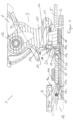
- the Figure 1 shows a heel holder 1 with a base 2, a heel machine 3, a pedal 4 and a ski brake 5.
- the heel machine 3 has a tensioning element 6 with a sole holder 7 and a connecting structure 10.
- the connecting structure 10 is connected to the base 2 in a first swivel joint 11 and to the clamping element 6 in a second swivel joint 12.
- the clamping element 6 can be in the swivel joint 12 relative to the base 2 and relative to the connecting structure 10 can be pivoted, the connecting structure 10 can be pivoted in the pivot joint 11 at least relative to the base 1.
- the base 2 has a carriage 24 which can be moved transversely to the longitudinal axis of the ski and enables additional transverse movements of the heel automatic 3 in extreme driving situations and a transverse release of the heel holder 1, for example in the event of a fall.
- a locking element 13 is connected to the underside 4a of the pedal 4, which in the exemplary embodiment has a rectangular profile which protrudes downwards from the underside 4a of the pedal 4 and forms a support surface 13a running parallel to the underside 4a.
- a counter-locking element 14 is guided in the base 2 or below the base 2 and is pressed at one end 14a by a spring element 15 with a spring force in the direction of travel of the ski 16.
- a support surface 14c is formed, which rests on the support surface 13a of the locking element 13, and thereby prevents the pedal 2 from moving from a second position shown, in which it rests on the surface of the ski 16 and the ski brake 5 in the shown position next to the ski, in which the ski brake 5 has no braking function, holds and locks.
- the counter-locking element 14 has an arm or projection 18 which projects vertically upward and which has a slope 18b at its upper end 18a.
- the counter-locking element 14 has a further projection 20 between the projection 18 and the end 14b, which can be guided in a groove in the base 2, for example, in order to support a straight guidance of the counter-locking element 14.
- the counter-locking element 14 can also be guided at least partially in a sleeve connected to, for example, the base 3 or guided in another known manner in order to prevent the counter-locking element 14 from bending or buckling.
- the projection 20 In the downhill position of the ski 16, the projection 20 is moved back against the direction of travel so far that its front end in the direction of travel comes to rest behind the edge 23 formed on the underside of the slide 24 guided in the base 2.
- the edge 23 can have an interruption in the middle, so that the counter-locking element 14 or the projection 20 can be moved freely in and against the direction of travel of the ski 16 when the carriage 24 lies in a permissible, non-triggering position in the base 2. If the carriage 24 leaves this position transversely to the direction of travel, the projection comes into an area of the edge 23 next to or outside the interruption and is thereby prevented by the edge 23 from being pushed back into the locking position by the spring 15, even if the pedal 4 is no longer pressed onto the ski surface by the ski boot.
- a nose or a pin 17 is formed, with an end 17a with a slope 17b.
- the ski brake 5 Since essentially at the same time the pedal 4 is depressed by the weight of the athlete getting into the binding, the ski brake 5 remains in the locked, non-braking position, with the locking now being established and held by the pedal 4.
- the locking element 13 and the counter-locking element 14 form a lock for the ski brake 5 when the pin 17 and the projection 18 do not interact with one another. This means that this locking can be active when the ski 16 is being transported or stored, or when the heel holder 1 or the heel automatic 3 is in a position in which the binding is used as a touring binding. If, on the other hand, the binding is used as a downhill binding, the locking element 13 and the counter-locking element 14 are no longer in locking engagement; the locking of the ski brake 5 in the position in which it does not brake the ski 16 is now ensured by the pedal 4 loaded with the skier .
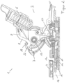
- the Figure 2 shows the heel holder 1 in the position for the downhill mode, in which both the connecting structure 10 and the tensioning element 6 of the heel automatic 3 are pivoted to the base 2.
- the pin 17 is completely retracted into the opening 21 of the base 2 and, via the interaction of the bevels 17b, 18b, has moved the counter-locking element 14 against the force of the spring element 15 against the direction of travel of the ski 16.
- the two support surfaces 13a, 14c no longer overlap, so that the ski brake 5 is no longer locked in the non-braking position by the interaction of the locking element 13 and the counter-locking element 14.
- This locking is now ensured by the pedal 4 in a known manner, since the athlete now holds the pedal 4 with his weight in the position shown on the top of the ski 16, in which the ski brake 5 is held in the non-braking position.
- the first climbing aid 8 and the second climbing aid 9 can also be seen, here in the position for downhill mode.
- the two climbing aids 8, 9 can be pivoted in a common joint 22 Heel automatics 3 or the tensioning element 6 are connected and have at least one common spring element 19, which secures the first climbing aid 8 and the second climbing aid 9 in at least the position shown against unwanted pivoting.
Landscapes
- Footwear And Its Accessory, Manufacturing Method And Apparatuses (AREA)
- Fittings On The Vehicle Exterior For Carrying Loads, And Devices For Holding Or Mounting Articles (AREA)
- Braking Arrangements (AREA)
Description
- Die Erfindung betrifft einen Fersenhalter für eine Skibindung wie zum Beispiel einen Ski. Der Fersenhalter umfasst eine Basis, einen Fersenautomaten, ein Pedal und eine Skibremse. Das Pedal bildet in bekannter Weise eine erste Verriegelung für die Skibremse.
- Der Fersenhalter umfasst darüber hinaus eine zweite Verriegelung für die Skibremse, die die Skibremse verriegelt, wenn der Fersenhalter nicht in einer für die Abfahrt mit dem Ski geeigneten Position ist.
- Insbesondere bei kombinierten Abfahrts- und Tourenbindungen sind herkömmliche Skibremsen mit Pedalansteuerung, die erst beim Einstieg in die Bindung in eine Position bewegt und dort gehalten werden, in der die Skibremse neben dem Ski angeordnet ist und keine Bremswirkung ausübt, ungeeignet. Im Tourenmodus wird das Pedal des Fersenhalters nicht mehr niedergehalten, wodurch die Bremse entriegelt ist. Das ist ein für das Tourengehen nicht akzeptabler Zustand, weshalb bei kombinierten Abfahrts- und Tourenbindungen heute noch Fangriemen für den Ski zum Einsatz kommen. Fangriemen werden von den Sportlern aber nicht mehr als zeitgemäße Lösung akzeptiert. Zudem weisen die herkömmlichen pedalbeaufschlagten Skibremsen den Nachteil auf, dass sie vor dem Einstieg des Sportlers in die Bindung und nach dem Ausstieg aus der Bindung nach unten vom Ski abstehen, wodurch das Transportvolumen der Skier größer ist, als es bei verriegelter Skibremse sein müsste.
- Die Patentschrift
FR 2 490 099 A1 EP 0 054 928 A1 zeigt ein Skistopper für Tourenbindungen mit Platten. Es ist daher eine Aufgabe der Erfindung einen Fersenhalter mit einer Skibremse zur Verfügung zu stellen, die zuverlässig auslöst, das heißt, ihre Bremswirkung entfaltet, wenn es beim Abfahren zu einem Auslösen des Fersenhalter, zum Beispiel durch einen Sturz, kommt, die gleichzeitig aber in einer verriegelten Position gehalten wird, wenn der Ski nicht in Benutzung ist oder als Tourenski benutzt wird. - Aus https://www.youtube.com/watch?v=3WvGTjy6Uyg ist eine gattungsgemäße Skibindung "Radical FT / ST" der Fa. Dynafit bekannt.
- Diese Aufgabe wird erfindungsgemäß durch den Gegenstand es Anspruch 1 gelöst.
- Die Erfindung betrifft einen Fersenhalter für einen Ski, insbesondere für einen Ski, der eine Basis, einen Fersenautomaten, eine Skibremse, ein Pedal, das von einer ersten Position in eine zweite Position bewegt werden kann, und in der ersten Position die Skibremse zum Bremsen freigibt und in einer zweiten Position die Skibremse neben dem Ski in einer Lage hält, in der die Skibremse das Ski nicht bremsen kann. Der Fersenhalter weist ferner eine Verriegelung für die Skibremse auf, mit der die Skibremse verriegelt werden kann, wenn sich das Pedal in der zweiten Position befindet.
- Mit anderen Worten weist die Skibremse zusätzlich zu der bekannten ersten mechanischen Verriegelung, die dadurch bewirkt wird, dass der Sportler in die Bindung einsteigt und durch sein Gewicht das Pedal aus seiner ersten Position über der Skioberfläche nach unten auf die Skioberfläche zu in eine zweite Position drückt, eine zweite mechanische Verriegelung auf. Die zweite Verriegelung hält die Skibremse in der verriegelten Position, das heißt, in einer Position in der sie neben dem Ski liegt und nicht nach unten über das Ski hinaus steht, bevor der Sportler in den Ski einsteigt, zum Beispiel beim Transport oder bei der Lagerung. Bei einer kombinierten Abfahrts- und Tourenbindung hält die zweite Verriegelung die Skibremse außerdem im Tourenmodus in der verriegelten Position.
- Unter Tourenmodus wird hier die Einstellung der Skiverbindung verstanden, die zum Tourengehen gewählt wird, das heißt, die Ferse des Schuhs ist vom Fersenhalter frei gegeben und kann sich beim Gehen aus dem Fersenhalter heraus bewegen. Der Abfahrtsmodus ist entsprechend die Einstellung der Bindung, in der der Schuh fest im Fersenhalter gehalten wird.
- Die Skibremse ist mit dem Pedal über eine Mechanik verbunden, die die Skibremse in die Bremsstellung vorspannt. Das heißt, dass, wenn das Pedal lastfrei ist, sich die Bremse immer in der Bremsstellung befindet, wenn das Pedal die einzige Verriegelung für die Bremse ist. Durch das Gewicht des Sportlers wird beim Einstieg in die Bindung das Pedal auf die Skioberfläche zu gedrückt und dadurch über eine Schwenkverbindung die Bremse nach oben neben das Ski geschwenkt und dort gehalten, solange das Pedal belastet ist. Bei einer plötzlichen Entlastung des Pedals, zum Beispiel beim Auslösen der Bindung bei einem Sturz, wird die Bremse ausgelöst und bremst das Ski ab.
- Die zweite Verriegelung für die Skibremse weist ein Verriegelungselement auf, das mit dem Pedal verbunden ist, und ein Gegenverriegelungselement, das in der Basis beweglich gelagert ist. Dabei ist das Verriegelungselement bevorzugt mit dem Pedal an dessen Unterseite verbunden und steht, wenn das Pedal in der Freigabeposition für die Skibremse ist, nach unten in Richtung Skioberfläche von der Pedalunterseite ab.
- Das Gegenverriegelungselement ist mittels eines Federelements in Richtung des Pedals, das heißt, in Richtung des Verriegelungselements am Pedal, vorgespannt, sodass bevorzugt ein Ende des Gegenverriegelungselements bei gespanntem Federelement in einem Verriegelungseingriff mit dem Verriegelungselement ist. Dieser Verriegelungseingriff kann beispielsweise darin bestehen, dass das Ende des Gegenverriegelungselements ein Ende des Verriegelungselements überlappt, wobei im Überlappungsbereich das Gegenverriegelungselement oberhalb des Verriegelungselements oder eines Teils des Verriegelungselements liegt, sodass das unbelastete Pedal nicht aus seiner zweiten Position in die erste Position bewegt werden kann. Alternativ kann das Gegenverriegelungselement in das Verriegelungselement eingreifen, um den Verriegelungseingriff herzustellen oder das Verriegelungselement gegen eine Federkraft in eine Verriegelungsposition drücken, wobei hier die Federkraft zum Entriegel des Verriegelungselements kleiner ist als die Federkraft zum Spannen des Gegenverriegelungselements.
- Das Gegenverriegelungselement kann sich in der Basis in einer Längsrichtung der Basis, respektive des Skis, von dem Verriegelungselement bis unter den Fersenhalter erstrecken, und in einem Bereich unterhalb des Fersenhalters einen senkrecht nach oben in Richtung des Fersenhalters abstehenden Vorsprung aufweist. Bevorzugt weist der Vorsprung an seinem vom Gegenverriegelungselement wegweisenden freien Ende eine Angriffsfläche auf, die mit einem mit dem Fersenautomat verbundenen Zapfen mit einer Gegenangriffsfläche zusammenwirken kann. Bei der Angriffsfläche und der Gegenangriffsfläche kann es sich insbesondere um Schrägflächen handeln, die so ausgebildet sind, dass eine Bewegung des Fersenautomats im Wesentlichen senkrecht zur Skioberfläche eine Bewegung des Gegenverriegelungselements in eine Richtung entgegen der Skilaufrichtung bewirkt.
- Der Zapfen kann beim Einstieg in den Fersenhalter und dem dadurch bedingten Verschwenken des Fersenautomaten in die Position, in der eine Sohlenhalter des Fersenautomats auf der Oberfläche der Sohle des Schuhs des Sportlers aufliegt, in Wirkungseingriff mit dem Vorsprung gelangen, wodurch das Gegenverriegelungselement gegen die Kraft des Federelements entgegen der Fahrtrichtung des Skis vom Verriegelungselement weg bewegt werden kann.
- Der Fersenautomat kann eine Spannvorrichtung mit dem Sohlenhalter und eine Verbindungsstruktur aufweisen, wobei die Verbindungsstruktur die Spannvorrichtung mit der Basis verbindet. Die Spannvorrichtung kann dabei um eine erste Achse schwenkbar mit der Verbindungsstruktur verbunden sein, und die Verbindungsstruktur kann um eine zweite Achse schwenkbarmit der Basis verbunden sein. Bei einem Fersenautomaten mit einer Verbindungsstruktur ist der Zapfen bevorzugt an der Verbindungsstruktur gebildet.
- Kommt es im Abfahrtsmodus zu einem Sturz und dadurch zu einem Auslösen, insbesondere einem Querauslösen der Bindung, bedeutet das, dass sich der Schuh aus der Bindung bewegt, das Pedal entlastet, und damit die Skibremse frei gibt. Der quer zur Skilängsachse verschobene Schlitten blockiert dabei gleichzeitig eine Bewegung des Gegenverriegelungselements in die Verriegelungsposition, sodass das Gegenverriegelungselement nicht in Eingriff mit dem Verriegelungselement gelangen kann, wodurch ein Lösen der Skibremse verhindert würde. Das bedeutet, dass bei einer Querauslösung der Skibindung bzw. des Fersenhalters der Ski durch die Skibremse uneingeschränkt abgebremst werden kann.
- Bei dem Fersenhalter handelt es sich bevorzugt um den Fersenalter einer Tourenbindung oder eine kombinierte Abfahrts- und Tourenbindung, wobei die Skibremse im Tourenmodus von der zweiten Verriegelung gesichert ist. Der Fersenhalter kann eine erste und eine zusätzliche zweite Steighilfe aufweist, wobei die erste Steighilfe den Schuh des Sportlers in einem ersten Steigwinkel stützt und die zweite Steighilfe den Schuh in einem zweiten Steigwinkel stützt, wobei der zweite Steigwinkel größer ist, als der erste Steigwinkel.
- Bei der Skibremse handelt es sich insbesondere um ein separates Teil, das nicht mit dem Fersenhalter verbunden ist, sondern unabhängig vom Fersenhalter zum Beispiel auf eine Schiene, die mit der Oberfläche des Skis verbunden ist, aufgeschoben werden kann.
- Ein weiterer Aspekt betrifft einen Ski mit einer kombinierten Abfahrt- und Tourenbindung mit einem Zehenhalter, einem Fersenhalter und einer Skibremse. Dabei handelt es sich bei dem Fersenhalter bevorzugt um den vorbeschriebenen Fersenhalter mit dem die Skibremse in einem Tourenmodus in einer nicht bremsenden Position gehalten werden kann.
- Im Folgenden wird eine Ausführung der Erfindung anhand von Figuren näher erläutert. Erfindungswesentliche Merkmale, die nur den Figuren entnommen werden können, können die Erfindung einzeln oder in den gezeigten Kombinationen vorteilhaft weiterbilden und gehören zum Umfang der Erfindung. Die Erfindung ist nicht auf das in den Figuren Gezeigte beschränkt.
- Die Figuren zeigen im Einzelnen:
- Figur 1
- Fersenhalter mit Skibremse die in der zweiten Verriegelung gehalten ist
- Figur 2
- Fersenhalter im Abfahrtsmodus mit gelöster zweiter Verriegelung
- In den folgenden zwei Figuren, die einen sehr detaillierten Aufbau eines Fersenhalters 1 anhand eines Ausführungsbeispiels zeigen, sind nur die für die Erfindung wesentlichen Teile mit Bezugszeichen versehen, um zu vermeiden, dass die Figuren durch zu viele unnötige Bezugszeichen unübersichtlich werden.
- Die
Figur 1 zeigt einen Fersenhalter 1 mit einer Basis 2, einem Fersenautomaten 3, einem Pedal 4 und einer Skibremse 5. Der Fersenautomat 3 weist ein Spannelement 6 mit einem Sohlenhalter 7 und eine Verbindungsstruktur 10 auf. Die Verbindungsstruktur 10 ist in einem ersten Schwenkgelenk 11 mit der Basis 2 verbunden und in einem zweiten Schwenkgelenk 12 mit dem Spannelement 6. Das Spannelement 6 kann im Schwenkgelenk 12 relativ zur Basis 2 und relativ zur Verbindungsstruktur 10 verschwenkt werden, die Verbindungsstruktur 10 kann im Schwenkgelenk 11 wenigstens relativ zur Basis 1 verschwenkt werden. Die Basis 2 weist im gezeigten Ausführungsbeispiel einen Schlitten 24 auf, der quer zur Skilängsachse bewegbar ist und zusätzliche Querbewegungen des Fersenautomaten 3 bei extremen Fahrsituationen und eine Querauslösung des Fersenhalters 1 zum Beispiel bei einem Sturz ermöglicht. - Mit der Unterseite 4a des Pedals 4 ist ein Verriegelungselement 13 verbunden, das im Ausführungsbeispiel ein rechtwinkliges Profil aufweist, das nach unten von der Unterseite 4a des Pedals 4 vorsteht und eine parallel zur Unterseite 4a verlaufende Auflagefläche 13a bildet.
- In der Basis 2 oder unterhalb der Basis 2 ist ein Gegenverriegelungselement 14 geführt, das an seinem einen Ende 14a von einem Federelement 15 mit einer Federkraft in Fahrrichtung des Skis 16 gedrückt wird. Am gegenüberliegenden Ende 14b ist eine Auflagefläche 14c ausgebildet, die auf der Auflagefläche 13a des Verriegelungselements 13 aufliegt, und dadurch verhindert, dass das Pedal 2 aus einer gezeigten zweiten Position, in der es auf der Oberfläche des Skis 16 aufliegt und die Skibremse 5 in der gezeigten Position neben dem Ski, in der die Skibremse 5 keine Bremsfunktion hat, hält und verriegelt. Nahe dem Ende 14a weist das Gegenverriegelungselement 14 einen senkrecht nach oben abstehenden Arm oder Vorsprung 18 auf, der an seinem oberen Ende 18a eine Schräge 18b aufweist. Im der gezeigten Ausführung weist das Gegenverriegelungselement 14 zwischen dem Vorsprung 18 und dem Ende 14b einen weiteren Vorsprung 20 auf, der zum Beispiel in der Basis 2 in einer Nut geführt sein kann, um ein Geradführung des Gegenverriegelungselements 14 zu unterstützen. Das Gegenverriegelungselement 14 kann auch wenigstens teilweise in einer mit zum Beispiel der Basis 3 verbundenen Hülse geführt werden oder auf andere bekannte Weise geführt sein, um ein Verbiegen oder Knicken des Gegenverriegelungselements 14 zu verhindern.
- Der Vorsprung 20 ist in der Abfahrtsposition des Skis 16 soweit gegen die Fahrtrichtung zurückbewegt, dass sein in Fahrtrichtung vorderes Ende hinter der an der Unterseite des in der Basis 2 geführten Schlittens 24 ausgebildete Kante 23 zu liegen kommt. Die Kante 23 kann mittig eine Unterbrechung aufweisen, sodass das Gegenverrieglungselement 14 bzw. der Vorsprung 20 frei in und gegen die Fahrtrichtung des Skis 16 bewegt werden kann, wenn der Schlitten 24 in einer zulässigen, nicht auslösenden Position in der Basis 2 liegt. Verlässt der Schlitten 24 diese Position quer zur Fahrtrichtung, so gerät der Vorsprung in einen Bereich der Kante 23 neben oder außerhalb der Unterbrechung und wird dadurch durch die Kante 23 daran gehindert durch die Feder 15 in die Verriegelungsposition zurück gedrückt zu werden, auch wenn das Pedal 4 nicht mehr durch den Skischuh auf die Skioberfläche gedrückt wird.
- An der Verbindungsstruktur 10, an ihrer der Skioberfläche zugewandten Seite, ist eine Nase oder ein Zapfen 17 angeformt, mit einem Ende 17a mit einer Schräge 17b. Der Zapfen 17 wird beim Verschwenken des Fersenautomaten 3 in die Position des Abfahrtsmodus, das heißt, in die Position, in der der Sohlenhalter 7 auf die Sohle des Schuhs drückt und der Fersenhalter 1 den Schuh fest in der Bindung hält, durch eine Öffnung 21 in der Basis 3 in Wirkverbindung mit dem Vorsprung 18 gebracht. Durch die miteinander wirkenden Schrägen 17b, 18b wird das Gegenverriegelungselement 14 gegen die Federkraft des Federelements 15 entgegen der Fahrtrichtung des Skis 16 bewegt. Dadurch löst sich die Verbindung der beiden Auflageflächen 13a, 14c und das Pedal 4 ist frei sich nach oben zu bewegen.
- Da im Wesentlichen gleichzeitig das Pedal 4 durch das Gewicht des in die Bindung einsteigenden Sportlers niedergedrückt wird, verbleibt die Skibremse 5 in der verriegelten, nicht bremsenden Position, wobei die Verriegelung jetzt durch das Pedal 4 hergestellt und gehalten wird.
- Aus dem eben Beschriebenen ist klar, dass das Verriegelungselement 13 und das Gegenverriegelungselement 14 eine Verriegelung für die Skibremse 5 bilden, wenn der Zapfen 17 und der Vorsprung 18 nicht miteinander agieren. Das heißt, diese Verriegelung kann dann aktiv sein, wenn der Ski 16 transportiert oder gelagert wird, oder wenn der Fersenhalter 1 bzw. der Fersenautomat 3 in einer Position ist, in der die Bindung als Tourenbindung benutzt wird. Wird die Bindung dagegen als Abfahrtsbindung genutzt, sind das Verriegelungselement 13 und das Gegenverriegelungselement 14 nicht mehr im Verriegelungseingriff, die Verriegelung der Skibremse 5 in der Position, in der sie den Ski 16 nicht bremst, wird jetzt durch das mit dem Skifahrer belastete Pedal 4 gewährleistet.
- Die
Figur 2 zeigt den Fersenhalter 1 in der Position für den Abfahrtsmodus, in der sowohl die Verbindungsstruktur 10, als auch das Spannelement 6 der Fersenautomatik 3 an die Basis 2 angeschwenkt sind. Der Zapfen 17 ist in die Öffnung 21 der Basis 2 vollständig eingefahren und hat über das Zusammenwirken der Schrägen 17b, 18b das Gegenverriegelungselement 14 gegen die Kraft des Federelements 15 entgegen der Fahrtrichtung des Skis 16 bewegt. Dadurch sind die beiden Auflageflächen 13a, 14c nicht mehr in Überlappung, sodass die Skibremse 5 nicht mehr durch das Zusammenwirken des Verriegelungselements 13 und des Gegenverriegelungselements 14 in der nicht bremsenden Position verriegelt ist. Diese Verriegelung wird jetzt durch das Pedal 4 in bekannter Weise gewährleistet, da jetzt der Sportler mit seinem Gewicht das Pedal 4 in der gezeigten Position auf der Oberseite des Skis 16 hält, in der die Skibremse 5 in der nicht bremsenden Position gehalten wird. - In der
Figur 2 sind auch die erste Steighilfe 8 und die zweite Steighilfe 9 zu sehen, hier in der Position für den Abfahrtmodus. Die beiden Steighilfen 8, 9 sind in einem gemeinsamen Gelenk 22 schwenkbar mit dem Fersenautomaten 3 bzw. dem Spannelement 6 verbunden und weisen wenigstens ein gemeinsames Federelement 19 auf, das die erste Steighilfe 8 und die zweite Steighilfe 9 in wenigstens der gezeigten Position gegen ein ungewolltes Verschwenken sichern. -
- 1
- Fersenhalter
- 2
- Basis,
- 3
- Fersenautomat
- 4
- Pedal
- 4a
- Unterseite
- 5
- Skibremse
- 6
- Spannelement
- 7
- Sohlenhalter
- 8
- Steighilfe
- 9
- Steighilfe
- 10
- Verbindungsstruktur
- 11
- Schwenkgelenk
- 12
- Schwenkgelenk
- 13
- Verriegelungselement
- 13a
- Auflagefläche
- 14
- Gegenverriegelungselement
- 14a
- Ende
- 14b
- Ende
- 14c
- Auflagefläche
- 15
- Federelement
- 16
- Ski
- 17
- Zapfen
- 17a
- Ende
- 17b
- Schräge
- 18
- Vorsprung
- 18a
- Ende
- 18b
- Schräge
- 19
- Federelement
- 20
- Vorsprung
- 21
- Öffnung
- 22
- Gelenk
- 23
- Kante
- 24
- Schlitten
Claims (11)
- Ski mit einer kombinierten Abfahrts- und Tourenbindung mit einem Zehenhalter und einem Fersenhalter, wobei(a) der Fersenhalter (1) eine Basis (2), einen Fersenautomaten (3) und ein Pedal (4) aufweist,(b) der Fersenhalter (1) eine erste und eine zusätzliche zweite Steighilfe (8, 9) aufweist,(c) die erste Steighilfe (8) den Schuh eines Sportlers in einem ersten Steigwinkel stützt und die zweite Steighilfe (9) den Schuh in einem zweiten Steigwinkel stützt, wobei der zweite Steigwinkel größer ist als der erste Steigwinkel,(d) und die beiden Steighilfen (8, 9) in einem gemeinsamen Gelenk (22) schwenkbar mit dem Fersenautomaten (3) verbunden sind,(e) wobei der Schuh in einem Abfahrtsmodus fest im Fersenhalter (1) gehalten und die Ferse des Schuhs in einem Tourenmodus vom Fersenhalter (1) frei gegeben ist und der Fersenhalter eine Skibremse (5) aufweist,(f) wobei das Pedal (4) von einer ersten Position, in der die Skibremse (5) nach unten vom Ski (16) absteht und eine Bremswirkung entfaltet, in eine zweite Position, in der die Skibremse (5) ohne Bremswirkung neben dem Ski (16) liegt, bewegbar ist, und(g) wobei der Fersenhalter (1) eine Verriegelung für die Skibremse (5) aufweist, mittels der die Skibremse (5) in der zweiten Position verriegelbar ist und die Verriegelung die Skibremse (5) im Tourenmodus in der verriegelten Position hält,
dadurch gekennzeichnet, dass(h) die Verriegelung ein Verriegelungselement (13) aufweist, das mit dem Pedal verbunden ist, und ein Gegenverriegelungselement (14), das in der Basis beweglich gelagert ist, und(i) wobei das Gegenverriegelungselement (14) mittels eines Federelements (15) in Richtung des Verriegelungselements (13) vorgespannt ist. - Ski mit einer kombinierten Abfahrts- und Tourenbindung nach Anspruch 1, wobei die Steighilfen (8, 9) wenigstens ein gemeinsames Federelement (19) aufweisen, das die erste Steighilfe (8) und die zweite Steighilfe (9) in wenigstens einer Position für den Abfahrtsmodus gegen ein ungewolltes Verschwenken sichert.
- Ski mit einer kombinierten Abfahrts- und Tourenbindung nach wenigstens einem der vorhergehenden Ansprüche, wobei der Fersenautomat (3) eine Spannvorrichtung (6) mit einem Sohlenhalter (7) und eine Verbindungsstruktur (10), die die Spannvorrichtung (6) mit der Basis (2) verbindet, aufweist.
- Ski mit einer kombinierten Abfahrts- und Tourenbindung nach dem unmittelbar vorhergehenden Anspruch, wobei die Spannvorrichtung (6) um eine erste Achse schwenkbar mit der Verbindungsstruktur (10) verbunden ist.
- Ski mit einer kombinierten Abfahrts- und Tourenbindung nach Anspruch 3 oder Anspruch 4, wobei die Verbindungsstruktur (10) um eine zweite Achse schwenkbar mit der Basis (2) verbunden ist.
- Ski mit einer kombinierten Abfahrts- und Tourenbindung nach wenigstens einem der vorhergehenden Ansprüche, wobei die Basis (2) einen Schlitten (24) aufweist, der quer zu einer Skilängsachse bewegbar ist und zusätzliche Querbewegungen des Fersenautomaten (3) und eine Querauslösung des Fersenhalters (1) ermöglicht.
- Ski mit einer kombinierten Abfahrts- und Tourenbindung nach wenigstens einem der vorhergehenden Ansprüche, wobei der Fersenhalter (1) und die Skibremse (5) separate Bauteile sind, die getrennt voneinander auf eine mit einer Oberfläche des Skis (16) verbundene Schiene aufschiebbar sind.
- Ski mit einer kombinierten Abfahrts- und Tourenbindung nach einem der vorhergehenden Ansprüche, wobei das Verriegelungselement (13) mit dem Pedal (4) an dessen Unterseite (4a) verbunden ist und in Richtung Skioberfläche von der Pedalunterseite absteht, und/oder wobei das Gegenverriegelungselement (14) mittels eines Federelements (15) in Fahrtrichtung des Skis (16) vorgespannt ist.
- Ski mit einer kombinierten Abfahrts- und Tourenbindung nach dem unmittelbar vorhergehenden Anspruch, wobei das Gegenverriegelungselement (14) sich in der Basis (2) in einer Längsrichtung des Skis (16) von dem Verriegelungselement (13) bis unter den Fersenautomaten (3) erstreckt und in einem Bereich unterhalb des Fersenautomaten (3) einen senkrecht nach oben in Richtung des Fersenautomaten (3) abstehenden Vorsprung (18) aufweist.
- Ski mit einer kombinierten Abfahrts- und Tourenbindung nach dem unmittelbar vorhergehenden Anspruch, wobei der Vorsprung (18) an seinem vom Gegenverriegelungselement (14) weg weisenden Ende (18a) eine Angriffsfläche (18b) aufweist, die mit einem mit dem Fersenautomaten (3) verbundenen Zapfen (17) mit einer Gegenangriffsfläche (17b) zusammenwirkt.
- Ski mit einer kombinierten Abfahrts- und Tourenbindung nach einem der zwei unmittelbar vorhergehenden Ansprüche, wobei der Zapfen (17) an der Verbindungsstruktur gebildet ist und/oder wobei der Zapfen (17) beim Einstieg eines Nutzers mit einem Schuh in den Fersenhalter (1) in Wirkungseingriff mit dem Vorsprung (18) gelangt und das Gegenverbindungselement (14) gegen die Kraft des Federelements (15) entgegen der Fahrtrichtung des Skis (16) vom Verrieglungselement (13) weg bewegt.
Priority Applications (1)
| Application Number | Priority Date | Filing Date | Title |
|---|---|---|---|
| EP18204581.5A EP3473307B1 (de) | 2012-08-07 | 2013-08-07 | Skibremse mit verriegelung |
Applications Claiming Priority (2)
| Application Number | Priority Date | Filing Date | Title |
|---|---|---|---|
| DE102012214001.8A DE102012214001B4 (de) | 2012-08-07 | 2012-08-07 | Skibremse mit Verriegelung |
| EP13179653.4A EP2695647B1 (de) | 2012-08-07 | 2013-08-07 | Skibremse mit Verriegelung |
Related Parent Applications (1)
| Application Number | Title | Priority Date | Filing Date |
|---|---|---|---|
| EP13179653.4A Division EP2695647B1 (de) | 2012-08-07 | 2013-08-07 | Skibremse mit Verriegelung |
Related Child Applications (2)
| Application Number | Title | Priority Date | Filing Date |
|---|---|---|---|
| EP18204581.5A Division EP3473307B1 (de) | 2012-08-07 | 2013-08-07 | Skibremse mit verriegelung |
| EP18204581.5A Division-Into EP3473307B1 (de) | 2012-08-07 | 2013-08-07 | Skibremse mit verriegelung |
Publications (3)
| Publication Number | Publication Date |
|---|---|
| EP3075422A1 EP3075422A1 (de) | 2016-10-05 |
| EP3075422B1 EP3075422B1 (de) | 2018-11-07 |
| EP3075422B2 true EP3075422B2 (de) | 2023-10-18 |
Family
ID=48985572
Family Applications (3)
| Application Number | Title | Priority Date | Filing Date |
|---|---|---|---|
| EP18204581.5A Active EP3473307B1 (de) | 2012-08-07 | 2013-08-07 | Skibremse mit verriegelung |
| EP13179653.4A Active EP2695647B1 (de) | 2012-08-07 | 2013-08-07 | Skibremse mit Verriegelung |
| EP16160420.2A Active EP3075422B2 (de) | 2012-08-07 | 2013-08-07 | Tourenbindung mit zwei steighilfen die an der gleiche achse auf dem fersenhalter angelenkt sind |
Family Applications Before (2)
| Application Number | Title | Priority Date | Filing Date |
|---|---|---|---|
| EP18204581.5A Active EP3473307B1 (de) | 2012-08-07 | 2013-08-07 | Skibremse mit verriegelung |
| EP13179653.4A Active EP2695647B1 (de) | 2012-08-07 | 2013-08-07 | Skibremse mit Verriegelung |
Country Status (2)
| Country | Link |
|---|---|
| EP (3) | EP3473307B1 (de) |
| DE (2) | DE102012214001B4 (de) |
Families Citing this family (8)
| Publication number | Priority date | Publication date | Assignee | Title |
|---|---|---|---|---|
| DE102012214001B4 (de) | 2012-08-07 | 2014-03-13 | Marker Deutschland Gmbh | Skibremse mit Verriegelung |
| FR2997309B1 (fr) * | 2012-10-29 | 2016-01-22 | Salomon Sas | Dispositif de retenue de fixation de ski avec cales de montee separees |
| FR3025435B1 (fr) | 2014-09-04 | 2016-09-02 | Salomon Sas | Fixation declenchable |
| DE102014222052A1 (de) | 2014-10-29 | 2016-05-04 | Fritz Barthel | Ferseneinheit für eine Gleitbrettbindung mit einer Bremsanordnung |
| DE102016000609B4 (de) * | 2016-01-23 | 2019-03-28 | Markus Steinke | Hinterbackenvorrichtung für eine Tourenskibindung |
| DE102016000608B4 (de) * | 2016-01-23 | 2017-08-31 | Markus Steinke | Hinterbackenvorrichtung für eine Tourenskibindung, umfassend eine Stopperplatte |
| DE102020124790A1 (de) * | 2020-09-23 | 2022-03-24 | Salewa Sport Ag | Bremsanordnung für eine Tourenbindung |
| DE102021100316A1 (de) * | 2021-01-11 | 2022-07-14 | Salewa Sport Ag | Bremsanordnung für eine Tourenbindung |
Citations (1)
| Publication number | Priority date | Publication date | Assignee | Title |
|---|---|---|---|---|
| WO2009105866A1 (en) † | 2008-02-29 | 2009-09-03 | G3 Genuine Guide Gear Inc. | Heel unit for alpine touring binding |
Family Cites Families (8)
| Publication number | Priority date | Publication date | Assignee | Title |
|---|---|---|---|---|
| AT368901B (de) * | 1980-09-16 | 1982-11-25 | Tyrolia Freizeitgeraete | Vorrichtung zum tourengehen |
| DE3048175A1 (de) * | 1980-12-19 | 1982-07-22 | Heinrich Wunder GmbH & Co KG, 8060 Dachau | Tourenbindung mit skistopper |
| IT1360160B1 (it) | 2005-03-01 | 2009-05-06 | Stefano Maruelli | Sistema alzatacco |
| WO2012024809A1 (de) * | 2010-08-27 | 2012-03-01 | Fritschi Ag - Swiss Bindings | Touren fersenbindung mit dynamischem gleitbereich |
| DE102011079210A1 (de) | 2011-07-14 | 2013-01-17 | Salewa Sport Ag | Ferseneinheit für eine Tourenskibindung |
| ITTO20120046A1 (it) * | 2012-01-21 | 2013-07-22 | Stefano Maruelli | Sistema di bloccaggio |
| DE202012002705U1 (de) * | 2012-03-14 | 2013-06-17 | Salewa Sport Ag | Ferseneinheit für eine Tourenbindung |
| DE102012214001B4 (de) | 2012-08-07 | 2014-03-13 | Marker Deutschland Gmbh | Skibremse mit Verriegelung |
-
2012
- 2012-08-07 DE DE102012214001.8A patent/DE102012214001B4/de not_active Expired - Fee Related
-
2013
- 2013-08-07 DE DE202013012328.1U patent/DE202013012328U1/de not_active Expired - Lifetime
- 2013-08-07 EP EP18204581.5A patent/EP3473307B1/de active Active
- 2013-08-07 EP EP13179653.4A patent/EP2695647B1/de active Active
- 2013-08-07 EP EP16160420.2A patent/EP3075422B2/de active Active
Patent Citations (1)
| Publication number | Priority date | Publication date | Assignee | Title |
|---|---|---|---|---|
| WO2009105866A1 (en) † | 2008-02-29 | 2009-09-03 | G3 Genuine Guide Gear Inc. | Heel unit for alpine touring binding |
Non-Patent Citations (2)
| Title |
|---|
| DYNAFIT: "RADICAL FT / ST 3D Video", YOUTUBE, 31 July 2012 (2012-07-31) † |
| S. ROMEO 'RANDOSTEVE': "Rando on the radical FT", TETONAT, 25 April 2011 (2011-04-25) † |
Also Published As
| Publication number | Publication date |
|---|---|
| EP3075422A1 (de) | 2016-10-05 |
| DE102012214001B4 (de) | 2014-03-13 |
| EP3075422B1 (de) | 2018-11-07 |
| EP3473307B1 (de) | 2025-07-30 |
| EP2695647B1 (de) | 2016-03-16 |
| EP3473307A1 (de) | 2019-04-24 |
| DE102012214001A1 (de) | 2014-02-13 |
| DE202013012328U1 (de) | 2016-03-29 |
| EP2695647A1 (de) | 2014-02-12 |
Similar Documents
| Publication | Publication Date | Title |
|---|---|---|
| EP3075422B2 (de) | Tourenbindung mit zwei steighilfen die an der gleiche achse auf dem fersenhalter angelenkt sind | |
| EP3498345B1 (de) | Leichtgewichtige skibindung mit erhöhter auslösesicherheit | |
| DE102012208915B4 (de) | Ferseneinheit mit Steighilfe und Bremsanordnung | |
| DE3310739A1 (de) | Bindungsanordnung zur festlegung eines skischuhes auf einem laufski mittels einer sicherheitsbindung | |
| CH619147A5 (de) | ||
| DE2756897A1 (de) | Sicherheitsskibindung | |
| DE2927059A1 (de) | Skischuh mit integrierter skibindung | |
| DE69917149T2 (de) | Gleitbrett für Alpineski oder Snowboarding | |
| DE2606988A1 (de) | Skibremse | |
| DE69216860T2 (de) | Vorrichtung zum verändern der natürlichen druckverteilung eines skis auf seinegleitfläche | |
| EP3848099B1 (de) | Ferseneinheit mit steighilfe für eine tourenbindung | |
| DE102013201723A1 (de) | Fersenhalter mit Schlitten zur Querauslösung und Hilfshebel | |
| EP1795236B1 (de) | Skibindung | |
| AT399100B (de) | Abstützungseinrichtung für den vorderen teil der sohle eines schuhs auf einem ski | |
| DE3240183A1 (de) | Backen einer sicherheitsskibindung | |
| EP0157091B1 (de) | Fersenhalter | |
| AT517977A2 (de) | Skibindung für eine biegsame Skischuhsohle | |
| DE102013224579B4 (de) | Gleitbrettbindung mit vorderer Halteeinrichtung und Bremseinrichtung | |
| DE3717101A1 (de) | Sicherheitsskibindung | |
| DE102013009762A1 (de) | Sicherheitsskibindungssystem | |
| DE3308754A1 (de) | Sicherheitsskibindung | |
| AT243140B (de) | Beschlag für Skischuhe | |
| DE2707771C3 (de) | Steuervorrichtung einer Skibremse für einen vom Skistiefel losgelösten Ski, die in einen Sohlenniederhalter für auslösende Skibindungen eingebaut ist | |
| DE3123329C2 (de) | Skibindung, insbesondere für Langlauf- oder Tourenski | |
| AT376131B (de) | Skibremse |
Legal Events
| Date | Code | Title | Description |
|---|---|---|---|
| PUAI | Public reference made under article 153(3) epc to a published international application that has entered the european phase |
Free format text: ORIGINAL CODE: 0009012 |
|
| 17P | Request for examination filed |
Effective date: 20160413 |
|
| AC | Divisional application: reference to earlier application |
Ref document number: 2695647 Country of ref document: EP Kind code of ref document: P |
|
| AK | Designated contracting states |
Kind code of ref document: A1 Designated state(s): AL AT BE BG CH CY CZ DE DK EE ES FI FR GB GR HR HU IE IS IT LI LT LU LV MC MK MT NL NO PL PT RO RS SE SI SK SM TR |
|
| RIC1 | Information provided on ipc code assigned before grant |
Ipc: A63C 9/08 20120101ALI20180329BHEP Ipc: A63C 9/084 20120101ALI20180329BHEP Ipc: A63C 7/10 20060101AFI20180329BHEP Ipc: A63C 9/00 20120101ALI20180329BHEP |
|
| GRAP | Despatch of communication of intention to grant a patent |
Free format text: ORIGINAL CODE: EPIDOSNIGR1 |
|
| STAA | Information on the status of an ep patent application or granted ep patent |
Free format text: STATUS: GRANT OF PATENT IS INTENDED |
|
| INTG | Intention to grant announced |
Effective date: 20180528 |
|
| GRAS | Grant fee paid |
Free format text: ORIGINAL CODE: EPIDOSNIGR3 |
|
| GRAA | (expected) grant |
Free format text: ORIGINAL CODE: 0009210 |
|
| STAA | Information on the status of an ep patent application or granted ep patent |
Free format text: STATUS: THE PATENT HAS BEEN GRANTED |
|
| AC | Divisional application: reference to earlier application |
Ref document number: 2695647 Country of ref document: EP Kind code of ref document: P |
|
| AK | Designated contracting states |
Kind code of ref document: B1 Designated state(s): AL AT BE BG CH CY CZ DE DK EE ES FI FR GB GR HR HU IE IS IT LI LT LU LV MC MK MT NL NO PL PT RO RS SE SI SK SM TR |
|
| REG | Reference to a national code |
Ref country code: GB Ref legal event code: FG4D Free format text: NOT ENGLISH |
|
| REG | Reference to a national code |
Ref country code: CH Ref legal event code: EP Ref country code: AT Ref legal event code: REF Ref document number: 1061389 Country of ref document: AT Kind code of ref document: T Effective date: 20181115 |
|
| REG | Reference to a national code |
Ref country code: DE Ref legal event code: R096 Ref document number: 502013011574 Country of ref document: DE |
|
| REG | Reference to a national code |
Ref country code: IE Ref legal event code: FG4D Free format text: LANGUAGE OF EP DOCUMENT: GERMAN |
|
| REG | Reference to a national code |
Ref country code: CH Ref legal event code: NV Representative=s name: RIEDERER HASLER AND PARTNER PATENTANWAELTE AG, CH |
|
| REG | Reference to a national code |
Ref country code: NL Ref legal event code: MP Effective date: 20181107 |
|
| REG | Reference to a national code |
Ref country code: LT Ref legal event code: MG4D |
|
| PG25 | Lapsed in a contracting state [announced via postgrant information from national office to epo] |
Ref country code: IS Free format text: LAPSE BECAUSE OF FAILURE TO SUBMIT A TRANSLATION OF THE DESCRIPTION OR TO PAY THE FEE WITHIN THE PRESCRIBED TIME-LIMIT Effective date: 20190307 Ref country code: FI Free format text: LAPSE BECAUSE OF FAILURE TO SUBMIT A TRANSLATION OF THE DESCRIPTION OR TO PAY THE FEE WITHIN THE PRESCRIBED TIME-LIMIT Effective date: 20181107 Ref country code: BG Free format text: LAPSE BECAUSE OF FAILURE TO SUBMIT A TRANSLATION OF THE DESCRIPTION OR TO PAY THE FEE WITHIN THE PRESCRIBED TIME-LIMIT Effective date: 20190207 Ref country code: LT Free format text: LAPSE BECAUSE OF FAILURE TO SUBMIT A TRANSLATION OF THE DESCRIPTION OR TO PAY THE FEE WITHIN THE PRESCRIBED TIME-LIMIT Effective date: 20181107 Ref country code: NO Free format text: LAPSE BECAUSE OF FAILURE TO SUBMIT A TRANSLATION OF THE DESCRIPTION OR TO PAY THE FEE WITHIN THE PRESCRIBED TIME-LIMIT Effective date: 20190207 Ref country code: ES Free format text: LAPSE BECAUSE OF FAILURE TO SUBMIT A TRANSLATION OF THE DESCRIPTION OR TO PAY THE FEE WITHIN THE PRESCRIBED TIME-LIMIT Effective date: 20181107 Ref country code: HR Free format text: LAPSE BECAUSE OF FAILURE TO SUBMIT A TRANSLATION OF THE DESCRIPTION OR TO PAY THE FEE WITHIN THE PRESCRIBED TIME-LIMIT Effective date: 20181107 Ref country code: LV Free format text: LAPSE BECAUSE OF FAILURE TO SUBMIT A TRANSLATION OF THE DESCRIPTION OR TO PAY THE FEE WITHIN THE PRESCRIBED TIME-LIMIT Effective date: 20181107 |
|
| PG25 | Lapsed in a contracting state [announced via postgrant information from national office to epo] |
Ref country code: PT Free format text: LAPSE BECAUSE OF FAILURE TO SUBMIT A TRANSLATION OF THE DESCRIPTION OR TO PAY THE FEE WITHIN THE PRESCRIBED TIME-LIMIT Effective date: 20190307 Ref country code: AL Free format text: LAPSE BECAUSE OF FAILURE TO SUBMIT A TRANSLATION OF THE DESCRIPTION OR TO PAY THE FEE WITHIN THE PRESCRIBED TIME-LIMIT Effective date: 20181107 Ref country code: SE Free format text: LAPSE BECAUSE OF FAILURE TO SUBMIT A TRANSLATION OF THE DESCRIPTION OR TO PAY THE FEE WITHIN THE PRESCRIBED TIME-LIMIT Effective date: 20181107 Ref country code: RS Free format text: LAPSE BECAUSE OF FAILURE TO SUBMIT A TRANSLATION OF THE DESCRIPTION OR TO PAY THE FEE WITHIN THE PRESCRIBED TIME-LIMIT Effective date: 20181107 Ref country code: NL Free format text: LAPSE BECAUSE OF FAILURE TO SUBMIT A TRANSLATION OF THE DESCRIPTION OR TO PAY THE FEE WITHIN THE PRESCRIBED TIME-LIMIT Effective date: 20181107 Ref country code: GR Free format text: LAPSE BECAUSE OF FAILURE TO SUBMIT A TRANSLATION OF THE DESCRIPTION OR TO PAY THE FEE WITHIN THE PRESCRIBED TIME-LIMIT Effective date: 20190208 |
|
| PG25 | Lapsed in a contracting state [announced via postgrant information from national office to epo] |
Ref country code: IT Free format text: LAPSE BECAUSE OF FAILURE TO SUBMIT A TRANSLATION OF THE DESCRIPTION OR TO PAY THE FEE WITHIN THE PRESCRIBED TIME-LIMIT Effective date: 20181107 Ref country code: CZ Free format text: LAPSE BECAUSE OF FAILURE TO SUBMIT A TRANSLATION OF THE DESCRIPTION OR TO PAY THE FEE WITHIN THE PRESCRIBED TIME-LIMIT Effective date: 20181107 Ref country code: PL Free format text: LAPSE BECAUSE OF FAILURE TO SUBMIT A TRANSLATION OF THE DESCRIPTION OR TO PAY THE FEE WITHIN THE PRESCRIBED TIME-LIMIT Effective date: 20181107 Ref country code: DK Free format text: LAPSE BECAUSE OF FAILURE TO SUBMIT A TRANSLATION OF THE DESCRIPTION OR TO PAY THE FEE WITHIN THE PRESCRIBED TIME-LIMIT Effective date: 20181107 |
|
| REG | Reference to a national code |
Ref country code: DE Ref legal event code: R026 Ref document number: 502013011574 Country of ref document: DE |
|
| PLBI | Opposition filed |
Free format text: ORIGINAL CODE: 0009260 |
|
| PLAX | Notice of opposition and request to file observation + time limit sent |
Free format text: ORIGINAL CODE: EPIDOSNOBS2 |
|
| PG25 | Lapsed in a contracting state [announced via postgrant information from national office to epo] |
Ref country code: SM Free format text: LAPSE BECAUSE OF FAILURE TO SUBMIT A TRANSLATION OF THE DESCRIPTION OR TO PAY THE FEE WITHIN THE PRESCRIBED TIME-LIMIT Effective date: 20181107 Ref country code: EE Free format text: LAPSE BECAUSE OF FAILURE TO SUBMIT A TRANSLATION OF THE DESCRIPTION OR TO PAY THE FEE WITHIN THE PRESCRIBED TIME-LIMIT Effective date: 20181107 Ref country code: RO Free format text: LAPSE BECAUSE OF FAILURE TO SUBMIT A TRANSLATION OF THE DESCRIPTION OR TO PAY THE FEE WITHIN THE PRESCRIBED TIME-LIMIT Effective date: 20181107 Ref country code: SK Free format text: LAPSE BECAUSE OF FAILURE TO SUBMIT A TRANSLATION OF THE DESCRIPTION OR TO PAY THE FEE WITHIN THE PRESCRIBED TIME-LIMIT Effective date: 20181107 |
|
| 26 | Opposition filed |
Opponent name: G3 GENUINE GUIDE GEAR INC. Effective date: 20190807 |
|
| PG25 | Lapsed in a contracting state [announced via postgrant information from national office to epo] |
Ref country code: SI Free format text: LAPSE BECAUSE OF FAILURE TO SUBMIT A TRANSLATION OF THE DESCRIPTION OR TO PAY THE FEE WITHIN THE PRESCRIBED TIME-LIMIT Effective date: 20181107 |
|
| PLBB | Reply of patent proprietor to notice(s) of opposition received |
Free format text: ORIGINAL CODE: EPIDOSNOBS3 |
|
| PG25 | Lapsed in a contracting state [announced via postgrant information from national office to epo] |
Ref country code: TR Free format text: LAPSE BECAUSE OF FAILURE TO SUBMIT A TRANSLATION OF THE DESCRIPTION OR TO PAY THE FEE WITHIN THE PRESCRIBED TIME-LIMIT Effective date: 20181107 |
|
| GBPC | Gb: european patent ceased through non-payment of renewal fee |
Effective date: 20190807 |
|
| PG25 | Lapsed in a contracting state [announced via postgrant information from national office to epo] |
Ref country code: MC Free format text: LAPSE BECAUSE OF FAILURE TO SUBMIT A TRANSLATION OF THE DESCRIPTION OR TO PAY THE FEE WITHIN THE PRESCRIBED TIME-LIMIT Effective date: 20181107 Ref country code: LU Free format text: LAPSE BECAUSE OF NON-PAYMENT OF DUE FEES Effective date: 20190807 |
|
| REG | Reference to a national code |
Ref country code: BE Ref legal event code: MM Effective date: 20190831 |
|
| PG25 | Lapsed in a contracting state [announced via postgrant information from national office to epo] |
Ref country code: IE Free format text: LAPSE BECAUSE OF NON-PAYMENT OF DUE FEES Effective date: 20190807 |
|
| PG25 | Lapsed in a contracting state [announced via postgrant information from national office to epo] |
Ref country code: GB Free format text: LAPSE BECAUSE OF NON-PAYMENT OF DUE FEES Effective date: 20190807 Ref country code: BE Free format text: LAPSE BECAUSE OF NON-PAYMENT OF DUE FEES Effective date: 20190831 |
|
| PG25 | Lapsed in a contracting state [announced via postgrant information from national office to epo] |
Ref country code: CY Free format text: LAPSE BECAUSE OF FAILURE TO SUBMIT A TRANSLATION OF THE DESCRIPTION OR TO PAY THE FEE WITHIN THE PRESCRIBED TIME-LIMIT Effective date: 20181107 |
|
| APAH | Appeal reference modified |
Free format text: ORIGINAL CODE: EPIDOSCREFNO |
|
| APBM | Appeal reference recorded |
Free format text: ORIGINAL CODE: EPIDOSNREFNO |
|
| APBP | Date of receipt of notice of appeal recorded |
Free format text: ORIGINAL CODE: EPIDOSNNOA2O |
|
| PG25 | Lapsed in a contracting state [announced via postgrant information from national office to epo] |
Ref country code: HU Free format text: LAPSE BECAUSE OF FAILURE TO SUBMIT A TRANSLATION OF THE DESCRIPTION OR TO PAY THE FEE WITHIN THE PRESCRIBED TIME-LIMIT; INVALID AB INITIO Effective date: 20130807 Ref country code: MT Free format text: LAPSE BECAUSE OF FAILURE TO SUBMIT A TRANSLATION OF THE DESCRIPTION OR TO PAY THE FEE WITHIN THE PRESCRIBED TIME-LIMIT Effective date: 20181107 |
|
| APBQ | Date of receipt of statement of grounds of appeal recorded |
Free format text: ORIGINAL CODE: EPIDOSNNOA3O |
|
| PG25 | Lapsed in a contracting state [announced via postgrant information from national office to epo] |
Ref country code: MK Free format text: LAPSE BECAUSE OF FAILURE TO SUBMIT A TRANSLATION OF THE DESCRIPTION OR TO PAY THE FEE WITHIN THE PRESCRIBED TIME-LIMIT Effective date: 20181107 |
|
| P01 | Opt-out of the competence of the unified patent court (upc) registered |
Effective date: 20230515 |
|
| APBU | Appeal procedure closed |
Free format text: ORIGINAL CODE: EPIDOSNNOA9O |
|
| PUAH | Patent maintained in amended form |
Free format text: ORIGINAL CODE: 0009272 |
|
| STAA | Information on the status of an ep patent application or granted ep patent |
Free format text: STATUS: PATENT MAINTAINED AS AMENDED |
|
| 27A | Patent maintained in amended form |
Effective date: 20231018 |
|
| AK | Designated contracting states |
Kind code of ref document: B2 Designated state(s): AL AT BE BG CH CY CZ DE DK EE ES FI FR GB GR HR HU IE IS IT LI LT LU LV MC MK MT NL NO PL PT RO RS SE SI SK SM TR |
|
| REG | Reference to a national code |
Ref country code: DE Ref legal event code: R102 Ref document number: 502013011574 Country of ref document: DE |
|
| PGFP | Annual fee paid to national office [announced via postgrant information from national office to epo] |
Ref country code: DE Payment date: 20250828 Year of fee payment: 13 |
|
| PGFP | Annual fee paid to national office [announced via postgrant information from national office to epo] |
Ref country code: FR Payment date: 20250826 Year of fee payment: 13 Ref country code: AT Payment date: 20250822 Year of fee payment: 13 |
|
| PGFP | Annual fee paid to national office [announced via postgrant information from national office to epo] |
Ref country code: CH Payment date: 20250901 Year of fee payment: 13 |