EP3062084B1 - Lubricant deterioration sensor - Google Patents
Lubricant deterioration sensor Download PDFInfo
- Publication number
- EP3062084B1 EP3062084B1 EP14855875.2A EP14855875A EP3062084B1 EP 3062084 B1 EP3062084 B1 EP 3062084B1 EP 14855875 A EP14855875 A EP 14855875A EP 3062084 B1 EP3062084 B1 EP 3062084B1
- Authority
- EP
- European Patent Office
- Prior art keywords
- lubricant
- sensor
- deterioration
- value
- light
- Prior art date
- Legal status (The legal status is an assumption and is not a legal conclusion. Google has not performed a legal analysis and makes no representation as to the accuracy of the status listed.)
- Active
Links
- 239000000314 lubricant Substances 0.000 title claims description 226
- 230000006866 deterioration Effects 0.000 title claims description 169
- 230000008859 change Effects 0.000 claims description 92
- 238000001514 detection method Methods 0.000 claims description 87
- 239000003086 colorant Substances 0.000 claims description 17
- 238000007689 inspection Methods 0.000 claims description 14
- 238000001816 cooling Methods 0.000 claims description 10
- 239000003921 oil Substances 0.000 description 51
- 238000000034 method Methods 0.000 description 21
- 230000003287 optical effect Effects 0.000 description 18
- 230000008569 process Effects 0.000 description 15
- 230000007423 decrease Effects 0.000 description 14
- 230000000694 effects Effects 0.000 description 8
- 239000000758 substrate Substances 0.000 description 8
- 239000010408 film Substances 0.000 description 7
- 230000003247 decreasing effect Effects 0.000 description 5
- 229910052751 metal Inorganic materials 0.000 description 5
- 239000002184 metal Substances 0.000 description 5
- 239000012535 impurity Substances 0.000 description 4
- 239000000126 substance Substances 0.000 description 4
- 230000005856 abnormality Effects 0.000 description 3
- 238000002835 absorbance Methods 0.000 description 3
- 238000004364 calculation method Methods 0.000 description 3
- 238000009792 diffusion process Methods 0.000 description 3
- 230000004044 response Effects 0.000 description 3
- VYPSYNLAJGMNEJ-UHFFFAOYSA-N silicon dioxide Inorganic materials O=[Si]=O VYPSYNLAJGMNEJ-UHFFFAOYSA-N 0.000 description 3
- 239000011800 void material Substances 0.000 description 3
- 238000010276 construction Methods 0.000 description 2
- 239000000446 fuel Substances 0.000 description 2
- 239000010720 hydraulic oil Substances 0.000 description 2
- 239000000463 material Substances 0.000 description 2
- 239000012528 membrane Substances 0.000 description 2
- 239000010705 motor oil Substances 0.000 description 2
- 235000012239 silicon dioxide Nutrition 0.000 description 2
- 239000010409 thin film Substances 0.000 description 2
- RZVHIXYEVGDQDX-UHFFFAOYSA-N 9,10-anthraquinone Chemical compound C1=CC=C2C(=O)C3=CC=CC=C3C(=O)C2=C1 RZVHIXYEVGDQDX-UHFFFAOYSA-N 0.000 description 1
- 229910052782 aluminium Inorganic materials 0.000 description 1
- XAGFODPZIPBFFR-UHFFFAOYSA-N aluminium Chemical compound [Al] XAGFODPZIPBFFR-UHFFFAOYSA-N 0.000 description 1
- 230000005540 biological transmission Effects 0.000 description 1
- 230000015556 catabolic process Effects 0.000 description 1
- 238000006731 degradation reaction Methods 0.000 description 1
- 238000010586 diagram Methods 0.000 description 1
- 238000001914 filtration Methods 0.000 description 1
- 239000011521 glass Substances 0.000 description 1
- 229910052500 inorganic mineral Inorganic materials 0.000 description 1
- 239000007788 liquid Substances 0.000 description 1
- ORUIBWPALBXDOA-UHFFFAOYSA-L magnesium fluoride Chemical compound [F-].[F-].[Mg+2] ORUIBWPALBXDOA-UHFFFAOYSA-L 0.000 description 1
- 229910001635 magnesium fluoride Inorganic materials 0.000 description 1
- 239000011707 mineral Substances 0.000 description 1
- 238000012806 monitoring device Methods 0.000 description 1
- 239000010453 quartz Substances 0.000 description 1
- 230000009467 reduction Effects 0.000 description 1
- 239000011347 resin Substances 0.000 description 1
- 229920005989 resin Polymers 0.000 description 1
- 239000000377 silicon dioxide Substances 0.000 description 1
Images


Classifications
-
- G—PHYSICS
- G01—MEASURING; TESTING
- G01N—INVESTIGATING OR ANALYSING MATERIALS BY DETERMINING THEIR CHEMICAL OR PHYSICAL PROPERTIES
- G01N33/00—Investigating or analysing materials by specific methods not covered by groups G01N1/00 - G01N31/00
- G01N33/26—Oils; Viscous liquids; Paints; Inks
- G01N33/28—Oils, i.e. hydrocarbon liquids
- G01N33/2888—Lubricating oil characteristics, e.g. deterioration
-
- G—PHYSICS
- G01—MEASURING; TESTING
- G01N—INVESTIGATING OR ANALYSING MATERIALS BY DETERMINING THEIR CHEMICAL OR PHYSICAL PROPERTIES
- G01N21/00—Investigating or analysing materials by the use of optical means, i.e. using sub-millimetre waves, infrared, visible or ultraviolet light
- G01N21/17—Systems in which incident light is modified in accordance with the properties of the material investigated
- G01N21/25—Colour; Spectral properties, i.e. comparison of effect of material on the light at two or more different wavelengths or wavelength bands
- G01N21/255—Details, e.g. use of specially adapted sources, lighting or optical systems
-
- G—PHYSICS
- G01—MEASURING; TESTING
- G01N—INVESTIGATING OR ANALYSING MATERIALS BY DETERMINING THEIR CHEMICAL OR PHYSICAL PROPERTIES
- G01N21/00—Investigating or analysing materials by the use of optical means, i.e. using sub-millimetre waves, infrared, visible or ultraviolet light
- G01N21/17—Systems in which incident light is modified in accordance with the properties of the material investigated
- G01N21/59—Transmissivity
- G01N21/5907—Densitometers
-
- G—PHYSICS
- G01—MEASURING; TESTING
- G01N—INVESTIGATING OR ANALYSING MATERIALS BY DETERMINING THEIR CHEMICAL OR PHYSICAL PROPERTIES
- G01N21/00—Investigating or analysing materials by the use of optical means, i.e. using sub-millimetre waves, infrared, visible or ultraviolet light
- G01N21/84—Systems specially adapted for particular applications
- G01N21/85—Investigating moving fluids or granular solids
- G01N21/8507—Probe photometers, i.e. with optical measuring part dipped into fluid sample
Definitions
- the present invention relates to a sensor for sensing a deterioration state of a lubricant or a cooling oil.
- Lubricant deterioration sensors have conventionally detected the light absorbance of the three primary colors in a visible light passing through a lubricant to determine the deterioration level of the lubricant based on the light absorbance of the three primary colors (see Japanese Patent Application Publication No. 2012-117951 ).
- the lubricant deterioration sensor disclosed in Japanese Patent Application Publication No. 2012-117951 includes a void portion receiving a lubricant, an LED for emitting visible light into the void portion, and a color sensor for receiving light from the LED having passed through the void portion.
- the LED emits light and the color sensor receives the light and outputs a sensing result on a device provided outside.
- GB 1 427 795 A , US 3,076,375 A , and EP 0 026 093 A1 describe colorimetric sensors for sensing liquids in transmission geometry, the sensors comprising logarithmic amplifiers for amplifying a detection signal value with a logarithmic function.
- EP 2 447 704 A1 describes an oil state monitoring device comprising a membrane filter for filtering the oil, first and second LEDs for illuminating opposing first and second major faces of the membrane filter, and first and second RGB sensors for detecting light reflected from and transmitted through the filter. From the detected light intensities brightness values and maximum color-component differences are calculated and compared to threshold values to determine a deterioration state of the oil.
- the lubricant deterioration sensor of Japanese Patent Application Publication No. 2012-117951 includes a linear amplifier as an operational amplifier for amplifying a voltage value outputted from the color sensor.
- transmissivity is taken on the abscissa consisting of a logarithmic axis, and the color sensor output (detection value) is taken on the ordinate. Supposing that a new lubricant results in a transmissivity value of one and a color sensor output value of one, lower transmissivity leads to sharply decreased color sensor output, as shown in Fig. 10 .
- Both the transmissivity and the color sensor output in Fig. 10 are in arbitrary units.
- the transmissivity In a region where the transmissivity is low, the amount of change of the color sensor output is extremely small with respect to an amount of change of the transmissivity, and thus there is possibility that the transmissivity cannot be accurately determined from the color sensor output value. Therefore, for a lubricant prone to stain and used in a region of low transmissivity, the deterioration state is sensed at lower accuracy as compared to lubricants used in a region of high transmissivity. Accordingly, there is a demand for a lubricant deterioration sensor that can maintain accuracy of sensing the deterioration state of a lubricant having low transmissivity.
- the present invention is made in view of such circumstances, and one object thereof is to provide a lubricant deterioration sensor that can maintain accuracy of sensing the deterioration state of a lubricant having low transmissivity, that is, under the condition of a small amount of light sensed.
- the invention is directed to a sensor for sensing a deterioration of a lubricant or a cooling oil as defined in claim 1.
- the sensor comprises: an inspection unit for receiving a lubricant or cooling oil to be inspected; a light emitting element for emitting detection light into the inspection unit; a light receiving element for obtaining a detection value indicating color information of the detection light having passed through the lubricant or cooling oil; and a logarithmic amplifier for amplifying the detection value with a logarithmic function and outputting the amplified detection value.
- the detection light emitted from the light emitting element passes through the lubricant in the inspection unit, and the light receiving element senses the color information of the detection light having passed through the lubricant.
- the detection value sensed by the light receiving element is amplified by a logarithmic amplifier with a logarithmic function and outputted.
- the detection value amplified by the logarithmic amplifier may change largely relative to the amount of change of the transmissivity in the region of low transmissivity as compared to the detection value amplified by the linear amplifier. Therefore, the transmissivity can be accurately determined from the detection value. Accordingly, it may be possible to maintain accuracy of sensing the deterioration state of a lubricant having low transmissivity.
- the lubricant deterioration sensor may preferably further include a collimator lens for producing parallel light rays disposed between the light emitting element and the inspection unit.
- the collimator lens for producing parallel light rays may be disposed between the light emitting element and the inspection unit.
- the detection light emitted from the light emitting element may be transformed by the collimator lens into parallel light rays, which can reach the light receiving element with restricted diffusion and convergence.
- the amount of light received by the light receiving element may be large enough to stabilize the sensing accuracy.
- the lubricant deterioration sensor may preferably further include a determination unit configured to calculate brightness from the detection value and determine that the lubricant has been deteriorated if the absolute value of the amount of change of the brightness per unit time is larger than a predetermined value.
- the lubricant deterioration sensor may provide a detection value amplified by the logarithmic amplifier, the amount of change of the detection value can be grasped in the region of low transmissivity.
- the absolute value of the amount of change of the brightness or the maximum color-component difference per unit time is larger than a predetermined value. Therefore, the determination can be accurately made from the amount of change of the brightness or the maximum color-component difference per unit time. It may be possible to grasp rapid deterioration of a lubricant and abnormality in a machine.
- the senor further includes a determination unit configured to calculate a maximum color-component difference and determine that the lubricant has been deteriorated if the amount of change of the maximum color-component difference per unit time is a negative value.
- the lubricant deterioration sensor provides a detection value amplified by the logarithmic amplifier, the amount of change of the detection value can be grasped in the region of low transmissivity. According to the invention, it is determined that the lubricant has been deteriorated if the amount of change of the maximum color-component difference per unit time is a negative value. Therefore, the determination can be accurately made from the amount of change of the maximum color-component difference per unit time. It may be possible to grasp rapid deterioration of a lubricant and abnormality in a machine.
- the lubricant deterioration sensor may preferably further include a determination unit configured to calculate brightness and a maximum color-component difference from the detection value and determine that the lubricant has been deteriorated if the amount of change of the maximum color-component difference per unit brightness is a negative value.
- the determination can be made more accurately than the case where the deterioration of the lubricant is determined from at least one of the brightness and the maximum color-component difference.
- the determination unit of the lubricant deterioration sensor may preferably determine that the lubricant has been deteriorated if the absolute value of the amount of change of the brightness is larger than a predetermined value and the brightness is smaller than the oil deterioration threshold value for determining deterioration of the lubricant.
- the lubricant may be determined that the lubricant has been deteriorated if the absolute value of the amount of change of the brightness is larger than a predetermined value and the brightness is smaller than the oil deterioration threshold value. Therefore, the deterioration of the lubricant can be determined accurately from the amount of change of the brightness and the brightness itself.
- the determination unit of the lubricant deterioration sensor may preferably determine that a machine is damaged if the absolute value of the amount of change of the brightness is larger than a predetermined value and the brightness is smaller than a machine damage threshold value for determining damage to the machine on which the lubricant deterioration sensor is installed.
- the lubricant may be determined that the lubricant has been deteriorated if the absolute value of the amount of change of the brightness is larger than a predetermined value and the brightness is smaller than a machine damage threshold value. Therefore, the damage to the machine can be determined accurately from the amount of change of the brightness and the brightness itself.
- an optical sensor capable of overcoming the above problem may sense the amount of light having passed through an inspection object and amplify the amount of light by a logarithmic amplifier, wherein an output voltage from the logarithmic amplifier is in a logarithmic relationship with an input voltage to the logarithmic amplifier.
- the optical sensor senses the amounts of two or more primary colors of light among the three primary colors of light and a logarithmic amplifier is provided for each of the two or more primary colors.
- the logarithmic amplifiers provided for individual primary colors may be designed to cancel the difference between the properties. Particularly in determining the deterioration state of a lubricant using the output from the optical sensor, there is no need of using different determination algorithms for each primary color.
- the logarithmic amplifier may preferably be disposed rearward of the light receiving surface of the light receiving element for sensing the amount of light, with respect to the direction of the light incident on the light receiving surface. Additionally, the logarithmic amplifier may be provided directly on the light receiving element, or an intermediate such as a circuit substrate of the optical sensor may be placed between the logarithmic amplifier and the light receiving surface of the light receiving element.
- the length of a wire between the light receiving element and the logarithmic amplifier may be minimized to make the whole size compact and minimize the external noise effect.
- the present invention enables sensing the difference in amount of light and maintaining accuracy of sensing the deterioration state of a lubricant having low transmissivity, that is, under the condition of a small amount of light sensed.
- the lubricant deterioration sensor may be installed on a machine using a lubricant, which is an inspection object, and configured to determine the deterioration of the lubricant and the damage to the machine.
- a lubricant which is an inspection object
- impurity substances may penetrate in the lubricant by friction or the like.
- damage to the machine can be determined from the state of the lubricant.
- the lubricant may include a hydraulic oil.
- the lubricant deterioration sensor 10 may include an optical sensor 20 and a personal computer (PC) 30. That is, the PC 30 may not be included in the structure of the optical sensor 20.
- the optical sensor 20 may include a column-shaped housing 11 made of metal or resin.
- a container section 11a may be provided in an upper area of the housing 11.
- the container section 11a may be covered with a cover 17.
- An external thread may be formed in the outer circumference of a lower area of the housing 11.
- the lubricant deterioration sensor 10 may be mounted on the machine with the external thread.
- the container section 11a may contain a circuit substrate 16.
- the circuit substrate 16 may be fixed on the housing 11.
- the logarithmic amplifier 26 may be positioned (on a back surface) to face the color sensor 22 across the circuit substrate 16. Thus, the length of a wire between the color sensor 22 and the logarithmic amplifier 26 may be minimized to make the whole size compact and minimize the external noise effect.
- the LED 21 may be a known device for emitting white light to be sensed.
- the color sensor 22 may be an RGB sensor that may output R value (corresponding to red), G value (corresponding to green), and B value (corresponding to blue) as color information in accordance with the amounts of light of wavelengths for red, green, and blue colors in the sensed light.
- the logarithmic amplifier 26, in which an output voltage and an input voltage may be in a logarithmic relationship, may be provided for each color.
- the R value, G value, and B value outputted from the color sensor 22 may be inputted into the logarithmic amplifier as input voltages and amplified with a logarithmic function such that the output voltages may be in a logarithmic relationship with the input voltages, and outputted to the determination unit 31 disposed outside.
- the LED driver 28 may adjust the electric current to the LED 21 for driving.
- the color sensor 22 in this arrangement may sense the amounts of red, green, and blue light; or alternatively, the color sensor 22 may sense the amounts of any one or two colors of light.
- the LED 21 and the color sensor 22 may be individually selected in accordance with the color to be sensed.
- the red, green, and blue colors may be independently sensed; or alternatively, the sum of the amounts of the three colors or any two of the three colors of light may be sensed.
- the outputs from the logarithmic amplifiers corresponding to the colors may be summed up by an operational amplifier; or alternatively, the values corresponding to the colors outputted from the color sensor 22 may be summed up by an operational amplifier and inputted to the logarithmic amplifier 26.
- the determination unit 31 may determine whether the lubricant has been deteriorated and whether the machine has been damaged, based on the detection value.
- the personal computer (PC) 30 may be connected to the lubricant deterioration sensor 10 to serve as the determination unit 31.
- the housing 11 may have a first through hole 11c extending in an optical axis direction of the detection light.
- the first through hole 11c may extend from the bottom of the container section 11a to the bottom of the housing 11.
- a first prism 23 may be provided on the bottom of the housing 11 at an exit of the first through hole 11c.
- the first prism 23 may be a right-angle prism made of a translucent material such as quartz and glass.
- the first prism 23 may have an incident surface 23a where the detection light having traveled through the first through hole 11c enters, a reflection surface 23b where the detection light having entered from the incident surface 23a is reflected, and an exit surface 23c through which the detection light reflected at the reflection surface 23b exits out.
- the incident surface 23a and the exit surface 23c may be optical-polished.
- the reflection surface 23b may be formed of a metal deposited film and a protection film.
- the metal deposited film is, for example, a thin aluminum film and formed on the outer side of the translucent material.
- the protection film is, for example, a silicon dioxide thin film or a magnesium fluoride thin film formed on the outer side of the metal deposited film to protect the metal deposited film.
- An angle of the reflection surface 23b with respect to the incident surface 23a may be set such that a light path of the light entering the reflection surface 23b is reflected at 90 degrees from the incident direction.
- a collimator lens 29 for producing parallel light rays may be provided between the LED 21 and the first prism 23 of the first through hole 11c.
- the collimator lens 29 may transform the detection light emitted from the LED 21 into parallel light rays with restricted diffusion and convergence.
- a second prism 24 may be provided on the bottom 11b of the housing 11.
- the second prism 24 may be disposed with a gap from the first prism 23.
- the second prism 24 may have the same structure as the first prism 23 and have an incident surface 24a, a reflection surface 24b, and an exit surface 24c.
- the gap between the first prism 23 and the second prism 24 may be an oil entering gap 25 where the lubricant enters and stays therein and the gap may serve as an inspection unit.
- the housing 11 may have a second through hole 11d extending in parallel with the first through hole 11c.
- the second through hole 11d may extend from the bottom of the container section 11a to the bottom 11b of the housing 11 and may be disposed between the second prism 24 and the color sensor 22.
- the white detection light emitted from the LED 21 may travel straight through the first through hole 11c and enters the first prism 23.
- the light path of the detection light is then bent at 90 degrees by the reflection surface 23b and enters the oil entering gap 25 from the exit surface 23c.
- the detection light further penetrates the lubricant in the oil entering gap 25 and then enters the second prism 24.
- the light path of the detection light having entered the second prism 24 may be bent at 90 degrees by the reflection surface 24b and then the detection light may travel straight through the second through hole 11d.
- the detection light may be received by the color sensor 22.
- the light path of the detection light emitted from the LED 21 may be reversed at 180 degrees by the first prism 23 and the second prism 24.
- the detection tight that has traveled through the lubricant may have a wavelength region thereof corresponding to the hue of the oil absorbed.
- Fig. 2 shows a color sensor output from a linear amplifier and a color sensor output from the logarithmic amplifier 26 with respect to the same type of lubricants.
- the abscissa in Fig. 2 is a logarithmic axis indicating transmissivity (corresponding to the amount of the detection light).
- the ordinate indicates color sensor outputs (detection value).
- Both the transmissivity and the color sensor output in Fig. 2 are in arbitrary units. Supposing that a new lubricant results in a transmissivity value of one and a color sensor output value of one, Fig. 2 shows detection values in accordance with deterioration.
- the detection values sensed by the logarithmic amplifier 26 are indicated by a solid line connecting the plotted squares.
- the detection values sensed by the linear amplifier are indicated by a broken line connecting the plotted squares.
- the amount of the detection light received by the color sensor 22 may decrease as the transmissivity decreases in accordance with deterioration of the lubricant; therefore, the color sensor output from the logarithmic amplifier 26 may also decrease in accordance with the property of the color sensor 22 (the color sensor output may decrease almost constantly for the color sensor 22 used in this embodiment).
- the color sensor output from the linear amplifier may decrease sharply from the transmissivity of one and become almost constant from the transmissivity of about 1/10.
- the lubricant deterioration sensor 10 including the logarithmic amplifier 26 may allow sufficient amount of change of the color sensor output relative to the amount of change of the transmissivity of the lubricant. Therefore, even in a region where the color sensor 22 may receive a small amount of light, the difference in transmissivity of the lubricant or the amount of light can be clearly grasped from the color sensor output values.
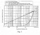
- Fig. 3 shows a diagram where the output results for a stained lubricant with the linear amplifier and the logarithmic amplifier are added into Fig. 2 .
- the color sensor output from the linear amplifier was decreased by 20% at the beginning of the detection as compared to the above new lubricant.
- the detection values for the new lubricant sensed by the linear amplifier are indicated by a solid line connecting the plotted circles.
- the detection values for the stained lubricant sensed by the linear amplifier are indicated by a thin broken line.
- the detection values for the stained lubricant sensed by the logarithmic amplifier are indicated by a thick broken line.
- the color sensor output from the linear amplifier for the stained lubricant at the transmissivity of one is 20% less than the color sensor output from the linear amplifier for the new lubricant at the transmissivity of one.
- the color sensor output from the logarithmic amplifier 26 for the same stained lubricant at the transmissivity of one is 2% less than the color sensor output from the logarithmic amplifier 26 for the new lubricant at the transmissivity of one. Therefore, even if the exit surface 23c or the incident surface 24a are stained, the amount of change of the color sensor output from the logarithmic amplifier 26 is large and thus the effect of stain can be restricted as compared to the linear amplifier.
- the detection values may be varied around the proper detection value due to presence of the detection light having passed through the air bubbles and the detection light not having passed through the air bubbles.
- the lubricant deterioration sensor 10 including the logarithmic amplifier 26 allows a large amount of change of the color sensor output from the logarithmic amplifier 26, the effect of the air bubbles can be restricted as compared to the linear amplifier.
- the oil entering gap 25 provided between the first prism 23 and the second prism 24 is widened, the light path is elongated and thus the detection values of the color sensor output may be decreased.
- the lubricant deterioration sensor 10 including the logarithmic amplifier 26 allows a large amount of change of the color sensor output from the logarithmic amplifier 26, the detection can be performed with the oil entering gap 25 widened.
- a lubricant having a high viscosity or a low fluidity can flow smoothly in the oil entering gap 25 provided between the first prism 23 and the second prism 24.
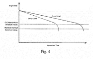
- the brightness may decrease as the operating time of the machine using the lubricant increases.
- the brightness (A E) may be calculated from the formula (1) shown below of an R value, a G value, and a B value.
- the dashed-dotted line in Fig. 4 shows a change in the brightness with respect to the operating time when a load on a movable component of the machine is large.
- the solid line in Fig. 4 shows a change in the brightness with respect to the operating time when the load on the movable component of the machine is small. Since the brightness rapidly decreases with the deterioration, the deterioration of the lubricant can be grasped from the amount of change of the brightness per unit time.
- the determination unit 31b may determine a deterioration state of the lubricant based on the brightness of the lubricant calculated from the detection value of the lubricant deterioration sensor 10.
- the brightness may correspond to the calculated value. More specifically, the determination unit 31 may determine the deterioration state of the lubricant based on comparison of the amount of change of the brightness per unit time to a predetermined value. If the deterioration of the lubricant is advanced, the determination unit 31 may determine the state of the lubricant based on the comparison between the brightness of the lubricant calculated from the detection value of the lubricant deterioration sensor 10 and an oil deterioration threshold value.
- the oil deterioration threshold value is used for determining whether the lubricant is deteriorated or not. When the brightness is less than or equal to the oil deterioration threshold value, the determination unit 31 may determine that the lubricant is deteriorated.
- the determination unit 31 may determine the state of the machine based on the brightness of the lubricant calculated from the detection value of the lubricant deterioration sensor 10. More specifically, the determination unit 31 may determine the state of the machine based on comparison between the brightness of the lubricant calculated from the detection value of the lubricant deterioration sensor 10 and the machine damage threshold value.
- the machine damage threshold value may be used for determining whether the machine is damaged or not, and may be smaller than the oil deterioration threshold value. When the brightness is less than or equal to the machine damage threshold value, the determination unit 31 may determine that the lubricant is deteriorated.
- the determination unit 31 may determine the deterioration state for each predetermined amount of the operation time of the machine having the lubricant deterioration sensor 10 installed therein. Alternatively, the state determination may be performed whenever need arises or only upon an instruction from a user.
- the determination unit 31 may initiate a deterioration state determination in response to an instruction to perform the deterioration state determination.
- the determination unit 31 may calculate the brightness from the detection value of the lubricant deterioration sensor 10 and calculate the amount of change of the brightness per unit time (step S11). More specifically, the determination unit 31 may calculate current brightness from the detection value sensed by the color sensor 22 of the lubricant deterioration sensor 10 and calculate the amount of change from the brightness obtained unit time before and the current brightness. The amount of change may be calculated from the difference between the current brightness and the brightness obtained the unit time before.
- the determination unit 31 may determine whether the absolute value of the amount of change of the brightness per unit time is larger than a predetermined value (step S12). More specifically, the determination unit 31 may perform comparison with the predetermined value that is larger than the absolute value of the amount of change during a short operation time, so as to determine whether the brightness has changed rapidly. Additionally, when the lubricant has deteriorated, the brightness may rapidly decrease relative to the operation time. If the absolute value of the amount of change of the brightness per unit time is smaller than the predetermined value (step S12: NO), the determination unit 31 may determine that there is no rapid change of the brightness and terminate the determination process.
- the determination unit 31 may determine whether or not the brightness is less than or equal to the oil deterioration determination threshold value (step S13). More specifically, when the determination unit 31 determines that the brightness is larger than the oil deterioration determination threshold value (step S13: NO), the determination unit 31 may determine that the lubricant is not deteriorated and terminate the determination process.
- the determination unit 31 determines whether or not the brightness is less than or equal to the machine damage threshold value (step S14). More specifically, when the determination unit 31 determines that the brightness is larger than the machine damage threshold value (step S14: NO), the determination unit 31 may determine that the lubricant is deteriorated (step S16) and terminate the determination process. In other words, when the brightness is larger than the machine damage threshold value and is less than or equal to the oil deterioration determination threshold value, the determination unit 31 determines that the lubricant is deteriorated but the machine is not damaged.
- the determination unit 31 may determine that the machine is damaged (step S15) and terminate the determination process. In other words, when the brightness is less than or equal to the machine damage threshold value, the determination unit 31 may determine that the lubricant is contaminated with impurity substances due to damage to the machine and determine that the machine is damaged.
- the brightness may be calculated from the detection value sensed by the lubricant deterioration sensor 10, and it is possible to easily determine the deterioration of the lubricant using the oil deterioration threshold value in addition to the amount of change of the brightness per unit time, and determine the damage to the machine using the machine damage threshold value.
- a lubricant deterioration sensor will be hereinafter described with reference to Figs. 6 and 7 .
- the deterioration determination method using the lubricant deterioration sensor 10 according to this embodiment is different from the first arrangement in that a maximum color difference is used as the calculation value instead of the brightness. The following description will be focused on the difference from the first arrangement.
- the lubricant deterioration sensor 10 of this embodiment may have the same structure as the lubricant deterioration sensor 10 of the first arrangement shown in Fig. 1 .
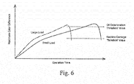
- the maximum color difference may increase with the operating time of the machine using the lubricant and then decrease once the maximum color difference reaches the extreme value.
- the dashed-dotted line in the figure shows a change in the maximum color difference with respect to the operating time when a load on a movable component of the machine is large.
- the solid line in the figure shows a change in the maximum color difference with respect to the operating time when the load on the movable component of the machine is small.
- the color component difference is an absolute value represented by
- the maximum color difference is the largest among these color component differences.
- the maximum color difference is a difference between the maximum color component value and the minimum color component value.
- the minimum color component value generally corresponds to the B value and the maximum color component value generally corresponds to the R value among the R, G, B values, so only the color difference
- the determination unit 31 may determine the deterioration state of the lubricant based on the maximum color difference of the lubricant calculated from the detection value of the lubricant deterioration sensor 10.
- the maximum color difference may correspond to the calculated value. More specifically, the determination unit 31 may determine the deterioration state of the lubricant based on comparison of the amount of change of the maximum color difference per unit time to a predetermined value. When the predetermined value is zero and the amount of change is negative, it is determined that the deterioration of the lubricant is advanced.
- the determination unit 31 may determine the deterioration state of the lubricant based on the maximum color difference of the lubricant calculated from the detection value of the lubricant deterioration sensor 10. More specifically, the determination unit 31 may determine the state of the lubricant based on comparison between the maximum color difference of the lubricant calculated from the detection value of the lubricant deterioration sensor 10 and the oil deterioration threshold value.
- the oil deterioration threshold value is used for determining whether the lubricant is deteriorated or not. When the maximum color difference is less than or equal to the oil deterioration determination threshold value, the determination unit 31 may determine that the lubricant is deteriorated.
- the determination unit 31 may determine the state of the machine based on the maximum color difference of the lubricant calculated from the detection value of the lubricant deterioration sensor 10. More specifically, the determination unit 31 may determine the state of the machine based on comparison between the maximum color difference of the lubricant calculated from the detection value of the lubricant deterioration sensor 10 and the machine damage threshold value.
- the machine damage threshold value may be used for determining whether the machine is damaged or not, and may be smaller than the oil deterioration threshold value. When the maximum color difference is less than or equal to the machine damage threshold value, the determination unit 31 may determine that the machine is damaged.
- the determination unit 31 may determine the deterioration state for each predetermined amount of the operation time of the machine having the lubricant deterioration sensor 10 installed therein. Alternatively, the state determination may be performed whenever need arises or only upon an instruction from a user.
- the determination unit 31 may initiate a deterioration state determination in response to an instruction to perform the deterioration state determination.
- the determination unit 31 may calculate the brightness from the detection value of the lubricant deterioration sensor 10 and calculate the amount of change of the maximum color difference per unit time (step S21). More specifically, the determination unit 31 may calculate the current maximum color difference from the detection value sensed by the color sensor 22 of the lubricant deterioration sensor 10 and calculate the amount of change from the maximum color difference obtained the unit time before and the current maximum color difference. The amount of change may be calculated from the difference between the current maximum color difference and the maximum color difference obtained the unit time before.
- the determination unit 31 may determine whether the amount of change of the maximum color difference per unit time is negative (step S22). When the lubricant is deteriorated, the maximum color difference increasing with the operation time may start decreasing once the maximum color difference reaches the extreme value. That is, the amount of change of the maximum color difference may turn from positive to negative. If the amount of change of the maximum color difference per unit time is positive (step S22: NO), the determination unit 31 may determine that there is no rapid change of the maximum color difference and terminate the determination process.
- the determination unit 31 may determine whether or not the maximum color difference is less than or equal to the oil deterioration threshold value (step S23). More specifically, when the determination unit 31 determines that the maximum color difference is larger than the oil deterioration threshold value (step S23: NO), the determination unit 31 may determine that the lubricant is not deteriorated and terminate the determination process.
- the determination unit 31 determines whether or not the maximum color difference is less than or equal to the machine damage threshold value (step S24). More specifically, when the determination unit 31 determines that the maximum color difference is larger than the machine damage threshold value (step S24: NO), the determination unit 31 may determine that the lubricant is deteriorated (step S26) and terminate the determination process. In other words, when the maximum color difference is larger than the machine damage threshold value and is less than or equal to the oil deterioration threshold value, the determination unit 31 may determine that the lubricant is deteriorated but the machine is not damaged.
- the determination unit 31 may determine that the machine is damaged (step S25) and terminate the determination process. In other words, when the maximum color difference is less than or equal to the machine damage threshold value, the determination unit 31 may determine that the lubricant is contaminated with impurity substances due to damage to the machine and determine that the machine is damaged.
- the maximum color difference may be calculated from the detection value sensed by the lubricant deterioration sensor 10, and it is possible to easily determine the deterioration of the lubricant using the oil deterioration threshold value in addition to the amount of change of the maximum color difference per unit time, and determine the damage to the machine using the machine damage threshold value.
- the following advantageous effects can be obtained in addition to the advantages (1) and (2) of the first embodiment. (3) It may be determined that the lubricant has been deteriorated if the amount of change of the maximum color difference per unit time is a negative value. Therefore, the determination can be accurately made from the amount of change of the maximum color difference per unit time.
- a second arrangement of a lubricant deterioration sensor will be hereinafter described with reference to Figs. 8 and 9 .
- the deterioration determination method using the lubricant deterioration sensor 10 according to this arrangement is different from the first arrangement in that the maximum color difference and the brightness are used as the calculation value. The following description will be focused on the difference from the first arrangement.
- the lubricant deterioration sensor 10 of this arrangement may have the same structure as the lubricant deterioration sensor 10 of the first arrangement shown in Fig. 1 .
- the abscissa indicates the brightness and the ordinate indicates the maximum color difference.
- the brightness may decrease with the operation time of the machine using the lubricant.
- the maximum color difference may increase as the brightness of the lubricant decreases, and may decrease once the maximum color difference reaches the extreme value.
- the determination unit 31 may determine the deterioration state of the lubricant based on the brightness and the maximum color difference of the lubricant calculated from the detection value of the lubricant deterioration sensor 10.
- the brightness and the maximum color difference may correspond to the calculated value. More specifically, the determination unit 31 may determine the deterioration state of the lubricant based on comparison of the amount of change of the maximum color difference per unit brightness to a predetermined value. When the predetermined value is zero and the amount of change is negative, it is determined that the deterioration of the lubricant is advanced.
- the determination unit 31 may determine the deterioration state of the lubricant based on the maximum color difference relative to the brightness of the lubricant calculated from the detection value of the lubricant deterioration sensor 10. More specifically, if the deterioration of the lubricant is advanced, the determination unit 31 may determine the state of the lubricant based on the comparison between the maximum color difference of the lubricant calculated from the detection value of the lubricant deterioration sensor 10 and an oil deterioration threshold value. The oil deterioration threshold value is used for determining whether the lubricant is deteriorated or not. When the maximum color difference is less than or equal to the oil deterioration threshold value, the determination unit 31 may determine that the lubricant is deteriorated.
- the determination unit 31 may determine the state of the machine based on the maximum color difference relative to the brightness of the lubricant calculated from the detection value of the lubricant deterioration sensor 10. More specifically, the determination unit 31 may determine the state of the machine based on comparison between the maximum color difference of the lubricant calculated from the detection value of the lubricant deterioration sensor 10 and the machine damage threshold value.
- the machine damage threshold value is used for determining whether the machine is damaged or not and is smaller than the oil deterioration threshold value. When the maximum color difference is less than or equal to the machine damage threshold value, the determination unit 31 may determine that the machine is damaged.
- the determination unit 31 may determine the deterioration state for each predetermined amount of the operation time of the machine having the lubricant deterioration sensor 10 installed therein. Alternatively, the state determination may be performed whenever need arises or only upon an instruction from a user.
- the determination unit 31 may initiate a deterioration state determination in response to an instruction to perform the deterioration state determination.
- the determination unit 31 may calculate the brightness and the maximum color difference from the detection value of the lubricant deterioration sensor 10 and calculate the amount of change of the maximum color difference per unit brightness (step S31). More specifically, the determination unit 31 may calculate the current brightness and the current maximum color difference from the detection value sensed by the color sensor 22 of the lubricant deterioration sensor 10 and calculate the amount of change from the maximum color difference obtained the unit brightness before and the current maximum color difference. The amount of change may be calculated from the difference between the current maximum color difference and the maximum color difference obtained the unit brightness before.
- the determination unit 31 may determine whether the amount of change of the maximum color difference per unit brightness is negative (step S32). When the lubricant is deteriorated, the maximum color difference increasing as the brightness decreases may start decreasing once the maximum color difference reaches the extreme value. That is, the amount of change of the maximum color difference may turn from positive to negative. If the amount of change of the maximum color difference per unit brightness is positive (step S32: NO), the determination unit 31 may determine that there is no rapid change of the maximum color difference and terminate the determination process.
- the determination unit 31 may determine whether or not the maximum color difference is less than or equal to the oil deterioration threshold value (step S33). More specifically, when the determination unit 31 determines that the maximum color difference is larger than the oil deterioration threshold value (step S33: NO), the determination unit 31 may determine that the lubricant is not deteriorated and terminate the determination process.
- step S34 determines whether or not the maximum color difference is less than or equal to the machine damage threshold value (step S34). More specifically, when the determination unit 31 determines that the maximum color difference is larger than the machine damage threshold value (step S34: NO), the determination unit 31 may determine that the lubricant is deteriorated (step S26) and terminate the determination process. In other words, when the maximum color difference is larger than the machine damage threshold value and is less than or equal to the oil deterioration threshold value, the determination unit 31 may determine that the lubricant is deteriorated but the machine is not damaged.
- step S34 determines that the maximum color difference is less than or equal to the machine damage threshold value (step S34: YES)
- the determination unit 31 may determine that the machine is damaged (step S35) and terminate the determination process.
- the determination unit 31 may determine that the lubricant is contaminated with impurity substances due to damage to the machine and determine that the machine is damaged.
- the brightness and the maximum color difference may be calculated from the detection value sensed by the lubricant deterioration sensor 10, and it is possible to easily determine the deterioration of the lubricant using the oil deterioration threshold value in addition to the amount of change of the maximum color difference per unit brightness, and determine the damage to the machine using the machine damage threshold value.
- the following advantageous effects can be obtained in addition to the advantages (1) and (2) of the first arrangement. (3) It may be determined that the lubricant has been deteriorated if the amount of change of the maximum color difference per unit brightness is a negative value. Therefore, the determination can be accurately made from the amount of change of the maximum color difference per unit brightness.
- the amount of change of the brightness per unit time is calculated, and it is determined that the lubricant is deteriorated if the absolute value of the amount of change of the brightness is larger than a predetermined value.
- the deterioration of the lubricant can be sufficiently determined only from the calculated brightness, it is not necessary to make the determination based on the amount of change of the brightness per unit time.
Landscapes
- Chemical & Material Sciences (AREA)
- Physics & Mathematics (AREA)
- Health & Medical Sciences (AREA)
- Life Sciences & Earth Sciences (AREA)
- General Health & Medical Sciences (AREA)
- Pathology (AREA)
- Immunology (AREA)
- General Physics & Mathematics (AREA)
- Analytical Chemistry (AREA)
- Biochemistry (AREA)
- Engineering & Computer Science (AREA)
- Spectroscopy & Molecular Physics (AREA)
- Oil, Petroleum & Natural Gas (AREA)
- Medicinal Chemistry (AREA)
- Food Science & Technology (AREA)
- General Chemical & Material Sciences (AREA)
- Chemical Kinetics & Catalysis (AREA)
- Investigating Or Analysing Materials By Optical Means (AREA)
Applications Claiming Priority (2)
| Application Number | Priority Date | Filing Date | Title |
|---|---|---|---|
| JP2013222381 | 2013-10-25 | ||
| PCT/JP2014/078485 WO2015060457A1 (ja) | 2013-10-25 | 2014-10-27 | 潤滑油劣化センサおよび光学センサ |
Publications (3)
| Publication Number | Publication Date |
|---|---|
| EP3062084A1 EP3062084A1 (en) | 2016-08-31 |
| EP3062084A4 EP3062084A4 (en) | 2017-06-28 |
| EP3062084B1 true EP3062084B1 (en) | 2021-02-17 |
Family
ID=52993039
Family Applications (1)
| Application Number | Title | Priority Date | Filing Date |
|---|---|---|---|
| EP14855875.2A Active EP3062084B1 (en) | 2013-10-25 | 2014-10-27 | Lubricant deterioration sensor |
Country Status (5)
| Country | Link |
|---|---|
| US (1) | US9995726B2 (es) |
| EP (1) | EP3062084B1 (es) |
| JP (1) | JP6194010B2 (es) |
| ES (1) | ES2855981T3 (es) |
| WO (1) | WO2015060457A1 (es) |
Families Citing this family (15)
| Publication number | Priority date | Publication date | Assignee | Title |
|---|---|---|---|---|
| JP6701909B2 (ja) * | 2016-04-15 | 2020-05-27 | 株式会社Ihi | 油判定装置、および、油判定方法 |
| JP6701910B2 (ja) * | 2016-04-15 | 2020-05-27 | 株式会社Ihi | 油判定装置、および、油判定方法 |
| JP2017215254A (ja) * | 2016-06-01 | 2017-12-07 | 株式会社Ihi | 潤滑状態判定装置及び潤滑状態判定方法 |
| JP6784063B2 (ja) * | 2016-06-01 | 2020-11-11 | 株式会社Ihi | 潤滑状態識別装置及び潤滑状態識別方法 |
| DE102016215099A1 (de) * | 2016-08-12 | 2018-02-15 | Zf Friedrichshafen Ag | Verfahren zum Vermessen eines Schmierspaltes zwischen geschmierten Kontaktelementen |
| US9988242B1 (en) | 2017-01-11 | 2018-06-05 | Otis Elevator Company | Elevator rail healthy monitoring method |
| JP6807259B2 (ja) * | 2017-03-28 | 2021-01-06 | 株式会社日立製作所 | 変圧器の絶縁油劣化診断システム及び方法 |
| CN110461219B (zh) * | 2017-04-07 | 2022-11-15 | 托伊实验室公司 | 用在卫生间环境中的生物监测用的装置、方法和系统 |
| CN110268143A (zh) * | 2017-04-28 | 2019-09-20 | 株式会社小松制作所 | 油的状态检测装置、作业机械、管理系统及油的状态检测方法 |
| US10942161B2 (en) | 2017-09-15 | 2021-03-09 | Exxonmobil Research And Engineering Company | Electrostatic varnish and precursor detection in lubricants |
| JP7179674B2 (ja) * | 2019-05-10 | 2022-11-29 | 株式会社日立製作所 | 潤滑油の診断方法および潤滑油の監視システム |
| JP6954405B2 (ja) * | 2019-05-16 | 2021-10-27 | ダイキン工業株式会社 | 液体センサ及び油圧ユニット |
| JP6966714B2 (ja) | 2019-08-01 | 2021-11-17 | ダイキン工業株式会社 | 液体劣化判定装置及び油圧ユニット |
| JP2021130793A (ja) | 2020-02-21 | 2021-09-09 | 出光興産株式会社 | 劣化測定装置、システム、及び方法、並びに潤滑油組成物 |
| JP2022078595A (ja) * | 2020-11-13 | 2022-05-25 | 日本ピラー工業株式会社 | 液体センサ |
Family Cites Families (11)
| Publication number | Priority date | Publication date | Assignee | Title |
|---|---|---|---|---|
| US3076375A (en) * | 1960-07-29 | 1963-02-05 | Sun Oil Co | Colorimeter with linear absorbance scale |
| GB1427795A (en) * | 1973-02-06 | 1976-03-10 | Dahms H | Endpoint detection in colourimetric titrations |
| EP0026093A1 (en) * | 1979-09-22 | 1981-04-01 | The British Petroleum Company p.l.c. | Oil-in-water monitor |
| JPH0731116B2 (ja) * | 1986-04-10 | 1995-04-10 | 株式会社日本自動車部品総合研究所 | 油劣化検出装置 |
| JPH02210247A (ja) * | 1989-02-10 | 1990-08-21 | Asahi Eng Co Ltd | 油の汚染度測定器 |
| JP2997173B2 (ja) * | 1994-10-13 | 2000-01-11 | 株式会社ジャパンエナジー | 油種判別センサ |
| JP4272308B2 (ja) * | 1999-02-04 | 2009-06-03 | エムケー精工株式会社 | オイル等劣化判定装置の試料収容セルおよびそれを使用したオイル等劣化判定装置 |
| JP4347296B2 (ja) * | 2003-11-17 | 2009-10-21 | ホーチキ株式会社 | 散乱光式煙感知器 |
| WO2010150526A1 (ja) * | 2009-06-23 | 2010-12-29 | 国立大学法人福井大学 | 油状態監視方法および油状態監視装置 |
| JP5839436B2 (ja) | 2010-12-02 | 2016-01-06 | ナブテスコ株式会社 | 光学センサ |
| JP5860739B2 (ja) * | 2012-03-19 | 2016-02-16 | ナブテスコ株式会社 | 減速機破損状態通知装置、減速機破損状態通知機能付機械システムおよび減速機破損状態通知プログラム |
-
2014
- 2014-10-27 EP EP14855875.2A patent/EP3062084B1/en active Active
- 2014-10-27 JP JP2015543941A patent/JP6194010B2/ja active Active
- 2014-10-27 US US15/030,783 patent/US9995726B2/en active Active
- 2014-10-27 ES ES14855875T patent/ES2855981T3/es active Active
- 2014-10-27 WO PCT/JP2014/078485 patent/WO2015060457A1/ja active Application Filing
Non-Patent Citations (1)
| Title |
|---|
| None * |
Also Published As
| Publication number | Publication date |
|---|---|
| JPWO2015060457A1 (ja) | 2017-03-09 |
| EP3062084A1 (en) | 2016-08-31 |
| ES2855981T3 (es) | 2021-09-27 |
| US20160252490A1 (en) | 2016-09-01 |
| JP6194010B2 (ja) | 2017-09-06 |
| EP3062084A4 (en) | 2017-06-28 |
| WO2015060457A1 (ja) | 2015-04-30 |
| US9995726B2 (en) | 2018-06-12 |
Similar Documents
| Publication | Publication Date | Title |
|---|---|---|
| EP3062084B1 (en) | Lubricant deterioration sensor | |
| EP3062085B1 (en) | Lubricant deterioration sensor | |
| EP3018469B1 (en) | State determination methods and state determination device | |
| JP6238338B2 (ja) | 光学式センサ及び光学式センサシステム | |
| CN103238059B (zh) | 用于工业机器人的减速机 | |
| AU2013278311B2 (en) | State determining method, state imparting system, and state determining program | |
| US20160309097A1 (en) | Cylinder head assembly | |
| US20220146412A1 (en) | Liquid deterioration determination device and hydraulic unit | |
| US20020069021A1 (en) | Automobile oil deterioration diagnosing apparatus | |
| JP6127138B2 (ja) | 対象物の劣化状態を判定する方法及び装置 | |
| US20030060984A1 (en) | Automobile oil deterioration diagnosing apparatus | |
| JP6954405B2 (ja) | 液体センサ及び油圧ユニット | |
| US10458841B2 (en) | Method for processing light sensor signals and light sensor system | |
| KR101274692B1 (ko) | 칼라 센서와 그를 이용한 백라이트 제어 장치 및 방법 |
Legal Events
| Date | Code | Title | Description |
|---|---|---|---|
| PUAI | Public reference made under article 153(3) epc to a published international application that has entered the european phase |
Free format text: ORIGINAL CODE: 0009012 |
|
| 17P | Request for examination filed |
Effective date: 20160511 |
|
| AK | Designated contracting states |
Kind code of ref document: A1 Designated state(s): AL AT BE BG CH CY CZ DE DK EE ES FI FR GB GR HR HU IE IS IT LI LT LU LV MC MK MT NL NO PL PT RO RS SE SI SK SM TR |
|
| AX | Request for extension of the european patent |
Extension state: BA ME |
|
| DAX | Request for extension of the european patent (deleted) | ||
| A4 | Supplementary search report drawn up and despatched |
Effective date: 20170529 |
|
| RIC1 | Information provided on ipc code assigned before grant |
Ipc: G01N 33/28 20060101ALI20170522BHEP Ipc: G01N 21/25 20060101AFI20170522BHEP Ipc: G01N 21/85 20060101ALN20170522BHEP Ipc: G01N 21/59 20060101ALI20170522BHEP |
|
| REG | Reference to a national code |
Ref country code: DE Ref legal event code: R079 Ref document number: 602014074961 Country of ref document: DE Free format text: PREVIOUS MAIN CLASS: G01N0021270000 Ipc: G01N0021250000 |
|
| RIC1 | Information provided on ipc code assigned before grant |
Ipc: G01N 21/85 20060101ALN20200804BHEP Ipc: G01N 21/25 20060101AFI20200804BHEP Ipc: G01N 33/28 20060101ALI20200804BHEP Ipc: G01N 21/59 20060101ALI20200804BHEP |
|
| GRAP | Despatch of communication of intention to grant a patent |
Free format text: ORIGINAL CODE: EPIDOSNIGR1 |
|
| STAA | Information on the status of an ep patent application or granted ep patent |
Free format text: STATUS: GRANT OF PATENT IS INTENDED |
|
| INTG | Intention to grant announced |
Effective date: 20200918 |
|
| GRAS | Grant fee paid |
Free format text: ORIGINAL CODE: EPIDOSNIGR3 |
|
| GRAA | (expected) grant |
Free format text: ORIGINAL CODE: 0009210 |
|
| STAA | Information on the status of an ep patent application or granted ep patent |
Free format text: STATUS: THE PATENT HAS BEEN GRANTED |
|
| AK | Designated contracting states |
Kind code of ref document: B1 Designated state(s): AL AT BE BG CH CY CZ DE DK EE ES FI FR GB GR HR HU IE IS IT LI LT LU LV MC MK MT NL NO PL PT RO RS SE SI SK SM TR |
|
| REG | Reference to a national code |
Ref country code: GB Ref legal event code: FG4D |
|
| REG | Reference to a national code |
Ref country code: CH Ref legal event code: EP |
|
| REG | Reference to a national code |
Ref country code: DE Ref legal event code: R096 Ref document number: 602014074961 Country of ref document: DE |
|
| REG | Reference to a national code |
Ref country code: AT Ref legal event code: REF Ref document number: 1362080 Country of ref document: AT Kind code of ref document: T Effective date: 20210315 |
|
| REG | Reference to a national code |
Ref country code: IE Ref legal event code: FG4D |
|
| REG | Reference to a national code |
Ref country code: LT Ref legal event code: MG9D |
|
| REG | Reference to a national code |
Ref country code: NL Ref legal event code: MP Effective date: 20210217 |
|
| PG25 | Lapsed in a contracting state [announced via postgrant information from national office to epo] |
Ref country code: NO Free format text: LAPSE BECAUSE OF FAILURE TO SUBMIT A TRANSLATION OF THE DESCRIPTION OR TO PAY THE FEE WITHIN THE PRESCRIBED TIME-LIMIT Effective date: 20210517 Ref country code: BG Free format text: LAPSE BECAUSE OF FAILURE TO SUBMIT A TRANSLATION OF THE DESCRIPTION OR TO PAY THE FEE WITHIN THE PRESCRIBED TIME-LIMIT Effective date: 20210517 Ref country code: HR Free format text: LAPSE BECAUSE OF FAILURE TO SUBMIT A TRANSLATION OF THE DESCRIPTION OR TO PAY THE FEE WITHIN THE PRESCRIBED TIME-LIMIT Effective date: 20210217 Ref country code: FI Free format text: LAPSE BECAUSE OF FAILURE TO SUBMIT A TRANSLATION OF THE DESCRIPTION OR TO PAY THE FEE WITHIN THE PRESCRIBED TIME-LIMIT Effective date: 20210217 Ref country code: GR Free format text: LAPSE BECAUSE OF FAILURE TO SUBMIT A TRANSLATION OF THE DESCRIPTION OR TO PAY THE FEE WITHIN THE PRESCRIBED TIME-LIMIT Effective date: 20210518 Ref country code: PT Free format text: LAPSE BECAUSE OF FAILURE TO SUBMIT A TRANSLATION OF THE DESCRIPTION OR TO PAY THE FEE WITHIN THE PRESCRIBED TIME-LIMIT Effective date: 20210617 Ref country code: LT Free format text: LAPSE BECAUSE OF FAILURE TO SUBMIT A TRANSLATION OF THE DESCRIPTION OR TO PAY THE FEE WITHIN THE PRESCRIBED TIME-LIMIT Effective date: 20210217 |
|
| REG | Reference to a national code |
Ref country code: AT Ref legal event code: MK05 Ref document number: 1362080 Country of ref document: AT Kind code of ref document: T Effective date: 20210217 |
|
| PG25 | Lapsed in a contracting state [announced via postgrant information from national office to epo] |
Ref country code: PL Free format text: LAPSE BECAUSE OF FAILURE TO SUBMIT A TRANSLATION OF THE DESCRIPTION OR TO PAY THE FEE WITHIN THE PRESCRIBED TIME-LIMIT Effective date: 20210217 Ref country code: LV Free format text: LAPSE BECAUSE OF FAILURE TO SUBMIT A TRANSLATION OF THE DESCRIPTION OR TO PAY THE FEE WITHIN THE PRESCRIBED TIME-LIMIT Effective date: 20210217 Ref country code: RS Free format text: LAPSE BECAUSE OF FAILURE TO SUBMIT A TRANSLATION OF THE DESCRIPTION OR TO PAY THE FEE WITHIN THE PRESCRIBED TIME-LIMIT Effective date: 20210217 Ref country code: NL Free format text: LAPSE BECAUSE OF FAILURE TO SUBMIT A TRANSLATION OF THE DESCRIPTION OR TO PAY THE FEE WITHIN THE PRESCRIBED TIME-LIMIT Effective date: 20210217 Ref country code: SE Free format text: LAPSE BECAUSE OF FAILURE TO SUBMIT A TRANSLATION OF THE DESCRIPTION OR TO PAY THE FEE WITHIN THE PRESCRIBED TIME-LIMIT Effective date: 20210217 |
|
| REG | Reference to a national code |
Ref country code: ES Ref legal event code: FG2A Ref document number: 2855981 Country of ref document: ES Kind code of ref document: T3 Effective date: 20210927 |
|
| PG25 | Lapsed in a contracting state [announced via postgrant information from national office to epo] |
Ref country code: IS Free format text: LAPSE BECAUSE OF FAILURE TO SUBMIT A TRANSLATION OF THE DESCRIPTION OR TO PAY THE FEE WITHIN THE PRESCRIBED TIME-LIMIT Effective date: 20210617 |
|
| PG25 | Lapsed in a contracting state [announced via postgrant information from national office to epo] |
Ref country code: EE Free format text: LAPSE BECAUSE OF FAILURE TO SUBMIT A TRANSLATION OF THE DESCRIPTION OR TO PAY THE FEE WITHIN THE PRESCRIBED TIME-LIMIT Effective date: 20210217 Ref country code: CZ Free format text: LAPSE BECAUSE OF FAILURE TO SUBMIT A TRANSLATION OF THE DESCRIPTION OR TO PAY THE FEE WITHIN THE PRESCRIBED TIME-LIMIT Effective date: 20210217 Ref country code: AT Free format text: LAPSE BECAUSE OF FAILURE TO SUBMIT A TRANSLATION OF THE DESCRIPTION OR TO PAY THE FEE WITHIN THE PRESCRIBED TIME-LIMIT Effective date: 20210217 Ref country code: SM Free format text: LAPSE BECAUSE OF FAILURE TO SUBMIT A TRANSLATION OF THE DESCRIPTION OR TO PAY THE FEE WITHIN THE PRESCRIBED TIME-LIMIT Effective date: 20210217 |
|
| REG | Reference to a national code |
Ref country code: DE Ref legal event code: R097 Ref document number: 602014074961 Country of ref document: DE |
|
| PG25 | Lapsed in a contracting state [announced via postgrant information from national office to epo] |
Ref country code: DK Free format text: LAPSE BECAUSE OF FAILURE TO SUBMIT A TRANSLATION OF THE DESCRIPTION OR TO PAY THE FEE WITHIN THE PRESCRIBED TIME-LIMIT Effective date: 20210217 Ref country code: SK Free format text: LAPSE BECAUSE OF FAILURE TO SUBMIT A TRANSLATION OF THE DESCRIPTION OR TO PAY THE FEE WITHIN THE PRESCRIBED TIME-LIMIT Effective date: 20210217 Ref country code: RO Free format text: LAPSE BECAUSE OF FAILURE TO SUBMIT A TRANSLATION OF THE DESCRIPTION OR TO PAY THE FEE WITHIN THE PRESCRIBED TIME-LIMIT Effective date: 20210217 |
|
| PLBE | No opposition filed within time limit |
Free format text: ORIGINAL CODE: 0009261 |
|
| STAA | Information on the status of an ep patent application or granted ep patent |
Free format text: STATUS: NO OPPOSITION FILED WITHIN TIME LIMIT |
|
| 26N | No opposition filed |
Effective date: 20211118 |
|
| PG25 | Lapsed in a contracting state [announced via postgrant information from national office to epo] |
Ref country code: AL Free format text: LAPSE BECAUSE OF FAILURE TO SUBMIT A TRANSLATION OF THE DESCRIPTION OR TO PAY THE FEE WITHIN THE PRESCRIBED TIME-LIMIT Effective date: 20210217 |
|
| PG25 | Lapsed in a contracting state [announced via postgrant information from national office to epo] |
Ref country code: SI Free format text: LAPSE BECAUSE OF FAILURE TO SUBMIT A TRANSLATION OF THE DESCRIPTION OR TO PAY THE FEE WITHIN THE PRESCRIBED TIME-LIMIT Effective date: 20210217 |
|
| PG25 | Lapsed in a contracting state [announced via postgrant information from national office to epo] |
Ref country code: IT Free format text: LAPSE BECAUSE OF FAILURE TO SUBMIT A TRANSLATION OF THE DESCRIPTION OR TO PAY THE FEE WITHIN THE PRESCRIBED TIME-LIMIT Effective date: 20210217 |
|
| REG | Reference to a national code |
Ref country code: CH Ref legal event code: PL |
|
| PG25 | Lapsed in a contracting state [announced via postgrant information from national office to epo] |
Ref country code: IS Free format text: LAPSE BECAUSE OF FAILURE TO SUBMIT A TRANSLATION OF THE DESCRIPTION OR TO PAY THE FEE WITHIN THE PRESCRIBED TIME-LIMIT Effective date: 20210617 |
|
| REG | Reference to a national code |
Ref country code: BE Ref legal event code: MM Effective date: 20211031 |
|
| GBPC | Gb: european patent ceased through non-payment of renewal fee |
Effective date: 20211027 |
|
| PG25 | Lapsed in a contracting state [announced via postgrant information from national office to epo] |
Ref country code: MC Free format text: LAPSE BECAUSE OF FAILURE TO SUBMIT A TRANSLATION OF THE DESCRIPTION OR TO PAY THE FEE WITHIN THE PRESCRIBED TIME-LIMIT Effective date: 20210217 |
|
| PG25 | Lapsed in a contracting state [announced via postgrant information from national office to epo] |
Ref country code: LU Free format text: LAPSE BECAUSE OF NON-PAYMENT OF DUE FEES Effective date: 20211027 Ref country code: GB Free format text: LAPSE BECAUSE OF NON-PAYMENT OF DUE FEES Effective date: 20211027 Ref country code: BE Free format text: LAPSE BECAUSE OF NON-PAYMENT OF DUE FEES Effective date: 20211031 |
|
| PG25 | Lapsed in a contracting state [announced via postgrant information from national office to epo] |
Ref country code: LI Free format text: LAPSE BECAUSE OF NON-PAYMENT OF DUE FEES Effective date: 20211031 Ref country code: CH Free format text: LAPSE BECAUSE OF NON-PAYMENT OF DUE FEES Effective date: 20211031 |
|
| PG25 | Lapsed in a contracting state [announced via postgrant information from national office to epo] |
Ref country code: FR Free format text: LAPSE BECAUSE OF NON-PAYMENT OF DUE FEES Effective date: 20211031 |
|
| PG25 | Lapsed in a contracting state [announced via postgrant information from national office to epo] |
Ref country code: IE Free format text: LAPSE BECAUSE OF NON-PAYMENT OF DUE FEES Effective date: 20211027 |
|
| PG25 | Lapsed in a contracting state [announced via postgrant information from national office to epo] |
Ref country code: HU Free format text: LAPSE BECAUSE OF FAILURE TO SUBMIT A TRANSLATION OF THE DESCRIPTION OR TO PAY THE FEE WITHIN THE PRESCRIBED TIME-LIMIT; INVALID AB INITIO Effective date: 20141027 |
|
| P01 | Opt-out of the competence of the unified patent court (upc) registered |
Effective date: 20230523 |
|
| PG25 | Lapsed in a contracting state [announced via postgrant information from national office to epo] |
Ref country code: CY Free format text: LAPSE BECAUSE OF FAILURE TO SUBMIT A TRANSLATION OF THE DESCRIPTION OR TO PAY THE FEE WITHIN THE PRESCRIBED TIME-LIMIT Effective date: 20210217 |
|
| PGFP | Annual fee paid to national office [announced via postgrant information from national office to epo] |
Ref country code: ES Payment date: 20231227 Year of fee payment: 10 |
|
| PGFP | Annual fee paid to national office [announced via postgrant information from national office to epo] |
Ref country code: DE Payment date: 20231020 Year of fee payment: 10 |
|
| PG25 | Lapsed in a contracting state [announced via postgrant information from national office to epo] |
Ref country code: MK Free format text: LAPSE BECAUSE OF FAILURE TO SUBMIT A TRANSLATION OF THE DESCRIPTION OR TO PAY THE FEE WITHIN THE PRESCRIBED TIME-LIMIT Effective date: 20210217 |