EP3060175B1 - Implant for transcatheter treatment of valve regurgitation - Google Patents
Implant for transcatheter treatment of valve regurgitation Download PDFInfo
- Publication number
- EP3060175B1 EP3060175B1 EP14856738.1A EP14856738A EP3060175B1 EP 3060175 B1 EP3060175 B1 EP 3060175B1 EP 14856738 A EP14856738 A EP 14856738A EP 3060175 B1 EP3060175 B1 EP 3060175B1
- Authority
- EP
- European Patent Office
- Prior art keywords
- implant
- anchor
- assistance device
- coaptation
- coaptation assistance
- Prior art date
- Legal status (The legal status is an assumption and is not a legal conclusion. Google has not performed a legal analysis and makes no representation as to the accuracy of the status listed.)
- Active
Links
Images


Classifications
-
- A—HUMAN NECESSITIES
- A61—MEDICAL OR VETERINARY SCIENCE; HYGIENE
- A61F—FILTERS IMPLANTABLE INTO BLOOD VESSELS; PROSTHESES; DEVICES PROVIDING PATENCY TO, OR PREVENTING COLLAPSING OF, TUBULAR STRUCTURES OF THE BODY, e.g. STENTS; ORTHOPAEDIC, NURSING OR CONTRACEPTIVE DEVICES; FOMENTATION; TREATMENT OR PROTECTION OF EYES OR EARS; BANDAGES, DRESSINGS OR ABSORBENT PADS; FIRST-AID KITS
- A61F2/00—Filters implantable into blood vessels; Prostheses, i.e. artificial substitutes or replacements for parts of the body; Appliances for connecting them with the body; Devices providing patency to, or preventing collapsing of, tubular structures of the body, e.g. stents
- A61F2/02—Prostheses implantable into the body
- A61F2/24—Heart valves ; Vascular valves, e.g. venous valves; Heart implants, e.g. passive devices for improving the function of the native valve or the heart muscle; Transmyocardial revascularisation [TMR] devices; Valves implantable in the body
- A61F2/2442—Annuloplasty rings or inserts for correcting the valve shape; Implants for improving the function of a native heart valve
-
- A—HUMAN NECESSITIES
- A61—MEDICAL OR VETERINARY SCIENCE; HYGIENE
- A61B—DIAGNOSIS; SURGERY; IDENTIFICATION
- A61B17/00—Surgical instruments, devices or methods
- A61B17/04—Surgical instruments, devices or methods for suturing wounds; Holders or packages for needles or suture materials
- A61B17/0401—Suture anchors, buttons or pledgets, i.e. means for attaching sutures to bone, cartilage or soft tissue; Instruments for applying or removing suture anchors
-
- A—HUMAN NECESSITIES
- A61—MEDICAL OR VETERINARY SCIENCE; HYGIENE
- A61F—FILTERS IMPLANTABLE INTO BLOOD VESSELS; PROSTHESES; DEVICES PROVIDING PATENCY TO, OR PREVENTING COLLAPSING OF, TUBULAR STRUCTURES OF THE BODY, e.g. STENTS; ORTHOPAEDIC, NURSING OR CONTRACEPTIVE DEVICES; FOMENTATION; TREATMENT OR PROTECTION OF EYES OR EARS; BANDAGES, DRESSINGS OR ABSORBENT PADS; FIRST-AID KITS
- A61F2/00—Filters implantable into blood vessels; Prostheses, i.e. artificial substitutes or replacements for parts of the body; Appliances for connecting them with the body; Devices providing patency to, or preventing collapsing of, tubular structures of the body, e.g. stents
- A61F2/02—Prostheses implantable into the body
- A61F2/24—Heart valves ; Vascular valves, e.g. venous valves; Heart implants, e.g. passive devices for improving the function of the native valve or the heart muscle; Transmyocardial revascularisation [TMR] devices; Valves implantable in the body
- A61F2/2442—Annuloplasty rings or inserts for correcting the valve shape; Implants for improving the function of a native heart valve
- A61F2/2454—Means for preventing inversion of the valve leaflets, e.g. chordae tendineae prostheses
-
- A—HUMAN NECESSITIES
- A61—MEDICAL OR VETERINARY SCIENCE; HYGIENE
- A61F—FILTERS IMPLANTABLE INTO BLOOD VESSELS; PROSTHESES; DEVICES PROVIDING PATENCY TO, OR PREVENTING COLLAPSING OF, TUBULAR STRUCTURES OF THE BODY, e.g. STENTS; ORTHOPAEDIC, NURSING OR CONTRACEPTIVE DEVICES; FOMENTATION; TREATMENT OR PROTECTION OF EYES OR EARS; BANDAGES, DRESSINGS OR ABSORBENT PADS; FIRST-AID KITS
- A61F2/00—Filters implantable into blood vessels; Prostheses, i.e. artificial substitutes or replacements for parts of the body; Appliances for connecting them with the body; Devices providing patency to, or preventing collapsing of, tubular structures of the body, e.g. stents
- A61F2/02—Prostheses implantable into the body
- A61F2/24—Heart valves ; Vascular valves, e.g. venous valves; Heart implants, e.g. passive devices for improving the function of the native valve or the heart muscle; Transmyocardial revascularisation [TMR] devices; Valves implantable in the body
- A61F2/2442—Annuloplasty rings or inserts for correcting the valve shape; Implants for improving the function of a native heart valve
- A61F2/2463—Implants forming part of the valve leaflets
-
- A—HUMAN NECESSITIES
- A61—MEDICAL OR VETERINARY SCIENCE; HYGIENE
- A61F—FILTERS IMPLANTABLE INTO BLOOD VESSELS; PROSTHESES; DEVICES PROVIDING PATENCY TO, OR PREVENTING COLLAPSING OF, TUBULAR STRUCTURES OF THE BODY, e.g. STENTS; ORTHOPAEDIC, NURSING OR CONTRACEPTIVE DEVICES; FOMENTATION; TREATMENT OR PROTECTION OF EYES OR EARS; BANDAGES, DRESSINGS OR ABSORBENT PADS; FIRST-AID KITS
- A61F2/00—Filters implantable into blood vessels; Prostheses, i.e. artificial substitutes or replacements for parts of the body; Appliances for connecting them with the body; Devices providing patency to, or preventing collapsing of, tubular structures of the body, e.g. stents
- A61F2/02—Prostheses implantable into the body
- A61F2/24—Heart valves ; Vascular valves, e.g. venous valves; Heart implants, e.g. passive devices for improving the function of the native valve or the heart muscle; Transmyocardial revascularisation [TMR] devices; Valves implantable in the body
- A61F2/2442—Annuloplasty rings or inserts for correcting the valve shape; Implants for improving the function of a native heart valve
- A61F2/2466—Delivery devices therefor
-
- A—HUMAN NECESSITIES
- A61—MEDICAL OR VETERINARY SCIENCE; HYGIENE
- A61B—DIAGNOSIS; SURGERY; IDENTIFICATION
- A61B17/00—Surgical instruments, devices or methods
- A61B17/00234—Surgical instruments, devices or methods for minimally invasive surgery
- A61B2017/00238—Type of minimally invasive operation
- A61B2017/00243—Type of minimally invasive operation cardiac
-
- A—HUMAN NECESSITIES
- A61—MEDICAL OR VETERINARY SCIENCE; HYGIENE
- A61B—DIAGNOSIS; SURGERY; IDENTIFICATION
- A61B17/00—Surgical instruments, devices or methods
- A61B17/04—Surgical instruments, devices or methods for suturing wounds; Holders or packages for needles or suture materials
- A61B17/0401—Suture anchors, buttons or pledgets, i.e. means for attaching sutures to bone, cartilage or soft tissue; Instruments for applying or removing suture anchors
- A61B2017/0414—Suture anchors, buttons or pledgets, i.e. means for attaching sutures to bone, cartilage or soft tissue; Instruments for applying or removing suture anchors having a suture-receiving opening, e.g. lateral opening
-
- A—HUMAN NECESSITIES
- A61—MEDICAL OR VETERINARY SCIENCE; HYGIENE
- A61B—DIAGNOSIS; SURGERY; IDENTIFICATION
- A61B17/00—Surgical instruments, devices or methods
- A61B17/04—Surgical instruments, devices or methods for suturing wounds; Holders or packages for needles or suture materials
- A61B17/0401—Suture anchors, buttons or pledgets, i.e. means for attaching sutures to bone, cartilage or soft tissue; Instruments for applying or removing suture anchors
- A61B2017/044—Suture anchors, buttons or pledgets, i.e. means for attaching sutures to bone, cartilage or soft tissue; Instruments for applying or removing suture anchors with a threaded shaft, e.g. screws
- A61B2017/0441—Suture anchors, buttons or pledgets, i.e. means for attaching sutures to bone, cartilage or soft tissue; Instruments for applying or removing suture anchors with a threaded shaft, e.g. screws the shaft being a rigid coil or spiral
-
- A—HUMAN NECESSITIES
- A61—MEDICAL OR VETERINARY SCIENCE; HYGIENE
- A61B—DIAGNOSIS; SURGERY; IDENTIFICATION
- A61B17/00—Surgical instruments, devices or methods
- A61B17/064—Surgical staples, i.e. penetrating the tissue
- A61B2017/0649—Coils or spirals
-
- A—HUMAN NECESSITIES
- A61—MEDICAL OR VETERINARY SCIENCE; HYGIENE
- A61F—FILTERS IMPLANTABLE INTO BLOOD VESSELS; PROSTHESES; DEVICES PROVIDING PATENCY TO, OR PREVENTING COLLAPSING OF, TUBULAR STRUCTURES OF THE BODY, e.g. STENTS; ORTHOPAEDIC, NURSING OR CONTRACEPTIVE DEVICES; FOMENTATION; TREATMENT OR PROTECTION OF EYES OR EARS; BANDAGES, DRESSINGS OR ABSORBENT PADS; FIRST-AID KITS
- A61F2/00—Filters implantable into blood vessels; Prostheses, i.e. artificial substitutes or replacements for parts of the body; Appliances for connecting them with the body; Devices providing patency to, or preventing collapsing of, tubular structures of the body, e.g. stents
- A61F2/02—Prostheses implantable into the body
- A61F2/24—Heart valves ; Vascular valves, e.g. venous valves; Heart implants, e.g. passive devices for improving the function of the native valve or the heart muscle; Transmyocardial revascularisation [TMR] devices; Valves implantable in the body
- A61F2/2412—Heart valves ; Vascular valves, e.g. venous valves; Heart implants, e.g. passive devices for improving the function of the native valve or the heart muscle; Transmyocardial revascularisation [TMR] devices; Valves implantable in the body with soft flexible valve members, e.g. tissue valves shaped like natural valves
-
- A—HUMAN NECESSITIES
- A61—MEDICAL OR VETERINARY SCIENCE; HYGIENE
- A61F—FILTERS IMPLANTABLE INTO BLOOD VESSELS; PROSTHESES; DEVICES PROVIDING PATENCY TO, OR PREVENTING COLLAPSING OF, TUBULAR STRUCTURES OF THE BODY, e.g. STENTS; ORTHOPAEDIC, NURSING OR CONTRACEPTIVE DEVICES; FOMENTATION; TREATMENT OR PROTECTION OF EYES OR EARS; BANDAGES, DRESSINGS OR ABSORBENT PADS; FIRST-AID KITS
- A61F2210/00—Particular material properties of prostheses classified in groups A61F2/00 - A61F2/26 or A61F2/82 or A61F9/00 or A61F11/00 or subgroups thereof
- A61F2210/0014—Particular material properties of prostheses classified in groups A61F2/00 - A61F2/26 or A61F2/82 or A61F9/00 or A61F11/00 or subgroups thereof using shape memory or superelastic materials, e.g. nitinol
-
- A—HUMAN NECESSITIES
- A61—MEDICAL OR VETERINARY SCIENCE; HYGIENE
- A61F—FILTERS IMPLANTABLE INTO BLOOD VESSELS; PROSTHESES; DEVICES PROVIDING PATENCY TO, OR PREVENTING COLLAPSING OF, TUBULAR STRUCTURES OF THE BODY, e.g. STENTS; ORTHOPAEDIC, NURSING OR CONTRACEPTIVE DEVICES; FOMENTATION; TREATMENT OR PROTECTION OF EYES OR EARS; BANDAGES, DRESSINGS OR ABSORBENT PADS; FIRST-AID KITS
- A61F2220/00—Fixations or connections for prostheses classified in groups A61F2/00 - A61F2/26 or A61F2/82 or A61F9/00 or A61F11/00 or subgroups thereof
- A61F2220/0008—Fixation appliances for connecting prostheses to the body
Definitions
- the present invention generally provides improved medical devices, typically for treatment of heart valve disease and/or for altering characteristics of one or more valves of the body.
- Embodiments of the invention include implants for treatment of mitral valve regurgitation.
- the human heart receives blood from the organs and tissues via the veins, pumps that blood through the lungs where the blood becomes enriched with oxygen, and propels the oxygenated blood out of the heart to the arteries so that the organ systems of the body can extract the oxygen for proper function. Deoxygenated blood flows back to the heart where it is once again pumped to the lungs.
- the heart includes four chambers: the right atrium (RA), the right ventricle (RV), the left atrium (LA) and the left ventricle (LV).
- the pumping action of the left and right sides of the heart occurs generally in synchrony during the overall cardiac cycle.
- the heart has four valves generally configured to selectively transmit blood flow in the correct direction during the cardiac cycle.
- the valves that separate the atria from the ventricles are referred to as the atrioventricular (or AV) valves.
- the AV valve between the left atrium and the left ventricle is the mitral valve.
- the AV valve between the right atrium and the right ventricle is the tricuspid valve.
- the pulmonary valve directs blood flow to the pulmonary artery and thence to the lungs; blood returns to the left atrium via the pulmonary veins.
- the aortic valve directs flow through the aorta and thence to the periphery. There are normally no direct connections between the ventricles or between the atria.
- the mechanical heartbeat is triggered by an electrical impulse which spreads throughout the cardiac tissue. Opening and closing of heart valves may occur primarily as a result of pressure differences between chambers, those pressures resulting from either passive filling or chamber contraction. For example, the opening and closing of the mitral valve may occur as a result of the pressure differences between the left atrium and the left ventricle.
- ventricular filling the aortic and pulmonary valves are closed to prevent back flow from the arteries into the ventricles.
- the AV valves open to allow unimpeded flow from the atria into the corresponding ventricles.
- ventricular systole i.e., ventricular emptying
- the tricuspid and mitral valves normally shut, forming a seal which prevents flow from the ventricles back into the corresponding atria.
- the AV valves may become damaged or may otherwise fail to function properly, resulting in improper closing.
- the AV valves are complex structures that generally include an annulus, leaflets, chordae and a support structure. Each atrium interfaces with its valve via an atrial vestibule.
- the mitral valve has two leaflets; the analogous structure of the tricuspid valve has three leaflets, and opposition or engagement of corresponding surfaces of leaflets against each other helps provide closure or sealing of the valve to prevent blood flowing in the wrong direction. Failure of the leaflets to seal during ventricular systole is known as malcoaptation, and may allow blood to flow backward through the valve (regurgitation).
- Heart valve regurgitation can have serious consequences to a patient, often resulting in cardiac failure, decreased blood flow, lower blood pressure, and/or a diminished flow of oxygen to the tissues of the body. Mitral regurgitation can also cause blood to flow back from the left atrium to the pulmonary veins, causing congestion. Severe valvular regurgitation, if untreated, can result in permanent disability or death.
- a variety of therapies have been applied for treatment of mitral valve regurgitation, and still other therapies may have been proposed but not yet actually used to treat patients. While several of the known therapies have been found to provide benefits for at least some patients, still further options would be desirable.
- pharmacologic agents such as diuretics and vasodilators
- medications can suffer from lack of patient compliance.
- a significant number of patients may occasionally (or even regularly) fail to take medications, despite the potential seriousness of chronic and/or progressively deteriorating mitral valve regurgitation.
- Pharmacological therapies of mitral valve regurgitation may also be inconvenient, are often ineffective (especially as the condition worsens), and can be associated with significant side effects (such as low blood pressure).
- open-heart surgery can replace or repair a dysfunctional mitral valve.
- annuloplasty ring repair the posterior mitral annulus can be reduced in size along its circumference, optionally using sutures passed through a mechanical surgical annuloplasty sewing ring to provide coaptation.
- Open surgery might also seek to reshape the leaflets and/or otherwise modify the support structure.
- open mitral valve surgery is generally a very invasive treatment carried out with the patient under general anesthesia while on a heart-lung machine and with the chest cut open.
- mitral valve replacement implants have been developed, with these implants generally replacing (or displacing) the native leaflets and relying on surgically implanted structures to control the blood flow paths between the chambers of the heart. While these various approaches and tools have met with differing levels of acceptance, none has yet gained widespread recognition as an ideal therapy for most or all patients suffering from mitral valve regurgitation.
- the implants comprise a coaptation assist body which remains within the blood flow path as the valve moves back and forth between an open-valve configuration and a closed valve configuration.
- the coaptation assist body may extend laterally across some, most, or all of the width of the valve opening, allowing coaptation between at least one of the native leaflets and the implant body.
- an implant which can be a cardiac implant, such as a coaptation assist body, cardiac patch, replacement heart valve, annuloplasty ring, pacemaker, sensor, or other device.
- At least one ribbon (e.g., clip) can be configured to extend from the implant body.
- the ribbon can be made of a shape memory material having a preformed shape with at least one curve.
- the ribbon is movable from a first compressed configuration to a second expanded configuration.
- the ribbon is configured to provide a force, such as a compressive force to clip to a body structure, such as an intracardiac structure.
- the intracardiac structure is a single native valve leaflet, and the force is applied between a first surface of the ribbon and a second surface of the ribbon opposed from the first surface of the ribbon.
- the compressive force can be sufficient to secure the implant in the vicinity of the native valve annulus.
- an implant for treating mal-coaptation of a heart valve can have an annulus and first and second leaflets with an open configuration and a closed configuration.
- the implant can include a coaptation assist body having a first coaptation surface configured to be disposed to the posterior leaflet, an opposed second surface configured to be disposed toward the anterior leaflet.
- the implant can include at least one ribbon configured to extend from the coaptation assist body.
- the ribbon can comprise a shape memory material having a preformed shape with at least one, two, or more discrete curves. The ribbon is movable from a first compressed configuration to a second expanded configuration.
- the ribbon can be configured to provide a compressive force on a native valve leaflet between a first surface and a second surface opposed from the first surface of the ribbon.
- the compressive force can be sufficient to secure the implant, such as the coaptation assist body, in the vicinity of the native valve annulus.
- the ribbon can be configured to provide ventricular attachment of the implant.
- the ribbon can comprise a nitinol alloy.
- the ribbon can be self-expanding.
- the implant can include a plurality of ribbons.
- the ribbon can be configured to engage the left ventricle wall.
- the ribbon can be configured to engage the anterior or the posterior leaflet.
- the ribbons resists movement of the implant.
- the implant can include at least one eyelet configured to accept a portion of an anchor there through.
- the implant can include a clip and pledget configured to secure the anchor to the coaptation assist body.
- an implant for treating mal-coaptation of a heart valve can have an annulus and first and second leaflets with an open configuration and a closed configuration.
- the implant can include a coaptation assist body having a first coaptation surface configured to be disposed to the posterior leaflet, an opposed second surface configured to be disposed toward the anterior leaflet.
- the implant can include a first anchor selectively deployable at a first target location.
- the implant can include a first rail coupled to the first anchor.
- the implant can include a second anchor selectively deployable, independently of the deployment of the first anchor, at a second location of the heart.
- the implant can include a second rail coupled to the second anchor.
- the coaptation assist body can be configured to slide along the first rail and the second rail to the implantation site.
- the coaptation assist body can be configured to slide along the first rail and the second rail when collapsed to fit within a delivery catheter.
- the coaptation assist body can be configured to slide along the first rail and the second rail when expanded upon exiting a delivery catheter.
- the first rail can be a suture.
- the second rail can be a suture.
- the ventricular anchor can be unfolded and held in relation to the coaptation assist body when the coaptation assist body slides along the first rail and the second rail.
- the ventricular anchor can traverse the mitral valve when the coaptation assist body slides along the first rail and the second rail.
- the implant can include a clip and pledget configured to secure the first anchor to the coaptation assist body.
- the implant can include a clip and pledget configured to secure the second anchor to the coaptation assist body.
- the first rail can be configured to be removed once first anchor is secured to the coaptation assist body.
- the second rail can be configured to be removed once second anchor is secured to the coaptation assist body.
- an implant for treating mal-coaptation of a heart valve comprises a coaptation assist body having a first coaptation surface, an opposed second surface, each surface bounded by a first lateral edge; a first anchor selectively deployable at a first target location of the heart near the second leaflet on the annulus and coupleable to the coaptation assist body near the superior edge; a second anchor selectively deployable, independently of the deployment of the first anchor, at a second location of the heart in the ventricle such that the coaptation assist body, when coupled to both the first anchor and the second anchor, extends from the first target location across the valve to the second target location; and wherein the second anchor is a ventricular anchor capable of engaging a wall of the left ventricle.
- a method for treating mal-coaptation of a heart valve in a patient the heart valve having an annulus and first and second leaflets, the first and second leaflets each comprising a proximal surface, a distal surface, a coaptation edge and an annular edge; the annulus further defining a valve plane, the valve plane separating an atrium proximally and a ventricle distally
- the method comprises: selectively deploying a first anchor into heart tissue near anterior and posterior fibrous trigones; selectively deploying a second anchor near the left ventricle wall; coupling the first anchor and the second anchor to a coaptation assist body comprising a coaptation surface and a leaflet surface such that the coaptation assist body is suspended across the valve plane from the atrium proximally to the ventricle distally.
- anterior leaflet could refer to one or more leaflets in a valve with multiple leaflets.
- the aortic valve or tricuspid valve typically has 3 leaflets so the “anterior” could refer to one or two of the medial, lateral, and posterior leaflets.
- the implants described herein will generally include a coaptation assist body (sometimes referred to herein as a valve body) which is generally along the blood flow path as the leaflets of the valve move back and forth between an open-valve configuration (with the anterior leaflet separated from valve body) and a closed-valve configuration (with the anterior leaflet engaging opposed surfaces of the valve body).
- the valve body will be disposed between the native leaflets to close the gap caused by mal-coaptation of the native leaflets by providing a surface for at least one of the native leaflets to coapt against, while effectively replacing second native leaflet in the area of the valve which it would occlude during systole, were it functioning normally.
- the gaps may be lateral (such as may be caused by a dilated left ventricle and/or mitral valve annulus) and/or axial (such as where one leaflet prolapses or is pushed by fluid pressure beyond the annulus when the valve should close).
- the coaptation assistance devices, implants, and methods described herein may be configured for treating functional and/or degenerative mitral valve regurgitation (MR) by creating an artificial coaptation zone within which at least one of the native mitral valve leaflets can seal.
- MR degenerative mitral valve regurgitation
- the structures and methods herein will largely be tailored to this application, though alternative embodiments might be configured for use in other valves of the heart and/or body, including the tricuspid valve, valves of the peripheral vasculature, the inferior vena cava, or the like.
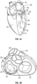
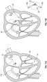
- Figs. 1A-1D the four chambers of the heart are shown, the left atrium 10, right atrium 12, left ventricle 14, and right ventricle 16.
- the mitral valve 20 is disposed between the left atrium 10 and left ventricle 14. Also shown are the tricuspid valve 22 which separates the right atrium 12 and right ventricle 16, the aortic valve 24, and the pulmonary valve 26.
- the mitral valve 20 is composed of two leaflets, the anterior leaflet 30 and posterior leaflet 32. In a healthy heart, the edges of the two leaflets oppose during systole at the coaptation zone 34.
- the fibrous annulus 36 provides attachment for the two leaflets 30, 32 of the mitral valve 20, referred to as the anterior leaflet 30 and the posterior leaflet 32.
- the leaflets 30, 32 are axially supported by attachment to the chordae tendinae 40.
- the chordae 40 attach to one or both of the papillary muscles 42, 44 of the left ventricle 14.
- the chordae 40 support structures tether the mitral valve leaflets 30, 32, allowing the leaflets 30, 32 to open easily during diastole but to resist the high pressure developed during ventricular systole.
- the shape and tissue consistency of the leaflets 30, 32 helps promote an effective seal or coaptation.
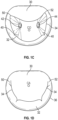
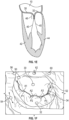
- the leading edges of the anterior and posterior leaflet come together along a funnel-shaped zone of coaptation 34, with a lateral cross-section 46 of the three-dimensional coaptation zone (CZ) being shown schematically in Fig. 1E .
- the anterior and posterior mitral leaflets 30, 32 are dissimilarly shaped.
- the anterior leaflet 30 is more firmly attached to the annulus overlying the central fibrous body (cardiac skeleton), and is somewhat stiffer than the posterior leaflet 32, which is attached to the more mobile posterior mitral annulus.
- Approximately 80 percent of the closing area is the anterior leaflet 30.
- the fibrous trigones 56, 60 form the septal and lateral extents of the central fibrous body 62.
- the fibrous trigones 56, 60 may have an advantage, in some embodiments, as providing a firm zone for stable engagement with one or more annular or atrial anchors.
- the coaptation zone 34 between the leaflets 30, 32 is not a simple line, but rather a curved funnel-shaped surface interface.
- the first 50 (lateral or left) and second 52 (septal or right) commissures are where the anterior leaflet 30 meets the posterior leaflet 32 at the annulus 36. As seen most clearly in the axial views from the atrium of Fig.
- an axial cross-section of the coaptation zone 34 generally shows the curved line CL that is separated from a centroid of the annulus CA as well as from the opening through the valve during diastole CO.
- the leaflet edges are scalloped, more so for the posterior leaflet 32 versus the anterior leaflet 30.
- Mal-coaptation can occur between one or more of these A-P (anterior-posterior) segment pairs A1/P1, A2/P2, and A3/P3, so that mal-coaptation characteristics may vary along the curve of the coaptation zone 34.
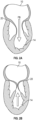
- a properly functioning mitral valve 20 of a heart is open during diastole to allow blood to flow along a flow path FP from the left atrium 10 toward the left ventricle 14 and thereby fill the left ventricle 14.
- the functioning mitral valve 20 closes and effectively seals the left ventricle 14 from the left atrium 10 during systole, first passively then actively by increase in ventricular pressure, thereby allowing contraction of the heart tissue surrounding the left ventricle 14 to advance blood throughout the vasculature.
- Fig. 3A-3B and 4A-4B there are several conditions or disease states in which the leaflet edges of the mitral valve 20 fail to oppose sufficiently and thereby allow blood to regurgitate in systole from the left ventricle 14 into the left atrium 10. Regardless of the specific etiology of a particular patient, failure of the leaflets to seal during ventricular systole is known as mal-coaptation and gives rise to mitral regurgitation.
- mal-coaptation can result from either excessive tethering by the support structures of one or both leaflets 30, 32, or from excessive stretching or tearing of the support structures.
- Other, less common causes include infection of the heart valve, congenital abnormalities, and trauma.
- Valve malfunction can result from the chordae tendinae 40 becoming stretched, known as mitral valve prolapse, and in some cases tearing of the chordae 40 or papillary muscle 44, known as a flail leaflet 64, as shown in Fig. 3A .
- the leaflet tissue itself the valves may prolapse so that the level of coaptation occurs higher into the left atrium 10, opening the valve 20 higher in the left atrium 10 during ventricular systole 66.
- Either one of the leaflets 30, 32 can undergo prolapse or become flail. This condition is sometimes known as degenerative mitral valve regurgitation.
- the leaflets 30, 32 of a normally structured valve may not function properly because of enlargement of or shape change in the valve annulus 36: so-called annular dilation 70.
- Such functional mitral regurgitation generally results from heart muscle failure and concomitant ventricular dilation.
- the excessive volume load resulting from functional mitral regurgitation can itself exacerbate heart failure, ventricular and annular dilation, thus worsening mitral regurgitation.
- Fig. 4A-4B illustrate the backflow BF of blood during systole in functional mitral valve regurgitation ( Fig. 4A ) and degenerative mitral valve regurgitation ( Fig. 4B ).
- the increased size of the annulus 36 in Fig. 4A coupled with increased tethering due to hypertrophy of the left ventricle 14 and papillary muscles 42, 44, prevents the anterior leaflet 30 and posterior leaflet 32 from opposing, thereby preventing coaptation.
- the tearing of the chordae 40 causes prolapse of the posterior leaflet 32 upward into the left atrium 10, which prevents opposition against the anterior leaflet 30. In either situation, the result is backflow of blood into the left atrium 10, which decreases the effectiveness of left ventricle compression.
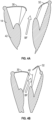
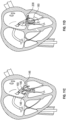
- Figs. 5A-5D show four views of an embodiment of a coaptation assistance device 80 which comprises a body 82.
- the body 82 comprises a first surface 84 disposed toward a mal-coapting native leaflet, in the instance of a mitral valve 20, the posterior leaflet 32 and a second surface 86 which may be disposed toward the anterior leaflet 30.
- the first and second surfaces 84, 86 can be considered a coaptation surface.
- the superior edge 90 of the body 82 may be curved to match the general shape of the annulus 36 or adjoining atrial wall.
- the coaptation assistance device 80 can comprise a frame 88 configured to provide structural support to the coaptation assistance device 80.
- the frame 88 is collapsible to fit within a delivery catheter, as described herein.
- the coaptation assistance device 80 may include one or a plurality of anchors to stabilize the device, such as atrial anchors and/or ventricular anchors, with the anchors optionally providing redundant fixation.
- the implant has lateral commissural anchors 92 which may help maintain the shape and position of the coaptation assistance device 80 once deployed in the heart.
- the lateral commissural anchors 92 are placed under the leaflets 30, 32 at the site of commissures 50, 52.
- the coaptation assistance device 80 can also have a posterior anchor 94.
- the posterior anchor 94 engages the area under the posterior leaflet 32. As shown in Fig.
- the commissural anchors 92 and the posterior anchors 94 can each comprise ribbons 98 that have a bias such that they can exert a force, and rest against the tissue of the heart, such as the ventricle.
- the ribbons 98 function as anchors and resist movement of the coaptation assistance device 80, and can do so without penetrating the myocardium in some embodiments.
- the positioning of the ribbons 98 against features of the anatomy may provide stability of the coaptation assistance device 80.
- the ribbons 98 may comprise bio-inert materials such as, for example, Platinum/Ir, a Nitinol alloy, and/or stainless steel.
- the ribbons 98 comprise NiTi.
- the ribbons 98 have a pre-determined curve.
- the material selection combined with the selected shape provides anchors 92, 94 that are spring loaded.
- the ribbons 98 extend in a direction, such as downward, from the frame 88.
- the ribbons 98 curve and then extend upward, forming a generally U-shaped configuration.
- the ribbons 98 comprise a rounded top surface configured to abut tissue.
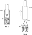
- the coaptation assistance device 80 is collapsed inside the delivery catheter 100 as shown in Figure 6A .
- the spring loaded ribbons 98 are capable of being collapsed within the delivery catheter. Upon exiting the catheter, the spring loaded ribbons 98 rapidly expand into the preformed shape.
- the ribbons 98 are provided for ventricular attachment.
- the ribbons 98 allow for very rapid attachment of the coaptation assistance device 80 to the tissue, since the ribbons 98 do not rely on annular sutures and do not require tying knots in some embodiments.
- the deployment of the ribbons 98 can be faster than engaging a helical anchor, for instance.
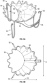
- the coaptation assistance device 80 includes an annular anchor 96.
- the annular anchor 96 can be, in some embodiments, a radially expandable stent-like structure, as shown in Figure 5A . Like the commissural anchors 92, the annular anchor 96 can be collapsed to fit inside a catheter, described herein. In some embodiments, the annular anchor 96 can be delivered to the site of the mitral valve 20. In some embodiments, the annular anchor 92 is intended for placement in the mitral annulus 36.
- the annular anchor 96 may include a plurality of barbs for acute fixation to the surrounding tissue. In some embodiments, the annular anchor 96 may be simply held in place via radial forces.
- the annular anchor 96 if it is included, may be covered with biocompatible materials such as ePTFE or Dacron to promote endothelialization and, optionally, chronic tissue in-growth or encapsulation of the annular anchor for additional stability.
- the atrial anchors may comprise a plurality of helixes, clips, harpoon or barb-shaped anchors, or the like, appropriate for screwing or engaging into the annulus 36 of the mitral valve 20, tissues of the ventricle 14, other tissues of the atrium 10, or other tissue.
- the body 82 can include one or more features such as eyelets or tethers to couple with the atrial anchors.
- the coaptation assistance device 80 has a geometry which permits it to traverse the mitral valve 20 between attachment sites in the left atrium 10 and left ventricle 14, to provide a coaptation surface 86 for the anterior leaflet 30 to coapt against, and attach to the left atrium 10 or annulus 36 such that it effectively seals off the posterior leaflet 32. In the instance that the posterior leaflet 32 is or has been removed, the coaptation assistance device 80 replaces the posterior leaflet 32.
- Different sized coaptation assistance device 80 can be placed such that the native anterior leaflet 30 opposes the coaptation surface 86 at the appropriately established coaptation point, blocking flow of blood during contraction of the left ventricle 14.
- a variety of sizes of coaptation assistance device 80 are provided, with differing dimensions configured to fit varying anatomies.
- a dimension A which is an inter-commissural distance. This distance may be, for example, within a range of about 20 mm to about 80 mm, and in one embodiment about 40 mm.
- dimension B which is an anterior-posterior diameter.
- This diameter may be, for example, within a range of about 20 mm to about 60 mm, and in one embodiment about 35 mm.
- a dimension C which is the anterior-posterior projection. This dimension may be within a range of, e.g., about 10 mm to about 30 mm depending on the mitral valve regurgitation (MR). For degenerative MR, this dimension may be, e.g., within a range of about 10 mm to about 20 mm. For functional MR, this dimension may be, e.g., within a range of about 20 mm to about 30 mm. As shown in Fig. 5D , there is a dimension D which is the coaptation assistance device 80 height. This dimension may be, e.g., within a range of about 20 mm to about 50 mm, and in one embodiment about 25 mm.
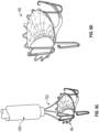
- Figs. 6A-6D an embodiment of the coaptation assistance device 80 is shown. It can be seen that in some embodiments, the coaptation assistance device 80 is collapsed inside the delivery catheter 100.
- the stent-like structure of the frame 88 of the coaptation assistance device 80 including the structure of the annular anchor 96 and commissural anchors 92 allows the coaptation assistance device 80 to be collapsed.
- a number of struts 102 may couple to the coaptation assistance device 80.
- the struts 102 may connect to the coaptation assistance device 80 at any number of locations, e.g., superior edge 90, annular anchor 94, commissural anchors 92, to a ventricular hub described herein.
- the struts 102 couple the coaptation assistance device 80 to the catheter 100 and/or implant introducer 104.
- Each strut 102 may comprise a single longitudinal element or be doubled over to comprise two or more strands.
- a single strut 102 may be comprised of a strand of Nitinol wire, suture, or other material which loops toward the superior aspect of the implant.
- the struts 102 could include clips, jaws, adhesive, or another mechanism to form a releasable attachment between the struts 102 and the coaptation assistance device 80.
- the struts 102 may be, as shown, placed such that they are relatively evenly spaced, or may be concentrated toward the center or lateral edges of the coaptation assistance device 80.
- the struts 102 may be coupleable with the anchors 92, 94, 96 which may be deployed into various locations including the mitral annulus 36, left atrium 10, left auricle, one of the fibrous trigones 56, or the left ventricle 14.
- the body 82 of the coaptation assistance device 80 can be delivered by a delivery catheter 100 and may be capable of expanding from a smaller profile to a larger profile to dimensions appropriate for placement in between the valve's native leaflets 30, 32.
- the coaptation assistance device 80 is expanded as it is exposed from the tip of the delivery catheter 100.
- the delivery catheter 100 is pulled back to expose the coaptation assistance device 80 as shown by the arrow in Fig. 6B .
- the exposed coaptation assistance device 80 is detached from the delivery catheter 100 as shown in Fig. 6D , for instance by releasing the struts 102.
- a coaptation assistance device 180 may be implanted through a minimally invasive or transcatheter technique utilizing a delivery system 106.
- the coaptation assistance device 180 can be substantially similar to the coaptation assistance device 80 described herein.
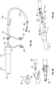
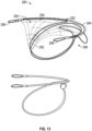
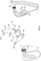
- the delivery system 106 can include one or more of the following devices: a transseptal sheath 110 shown in Figure 7 , an anchor delivery catheter 112 shown in Figure 8 , an implant delivery catheter 114 shown in Figures 9A-9B , and a clip delivery catheter 116 shown in Figure 10 .
- the delivery system 106 may include a transseptal sheath 110 having a shaft 120 that may be made of a polymeric or other material.
- the shaft 120 is a braid or coil reinforced polymer shaft. In some embodiments, the shaft 120 has multiple durometers, such as a first smaller durometer at a first location and a second larger durometer at a second location distal or proximal to the first location. In some embodiments, the transseptal sheath 110 is pre-shaped. The shaft 120 can include at least one through lumen (e.g., two, or more through lumens). In some embodiments, the transseptal sheath 110 comprises an actively deflectable tip 122 to facilitate navigation into the left ventricle 14. The deflectable tip 122 can be controlled by various mechanisms, for instance via pullwires operably attached to the deflectable tip 122 and connected to a proximal control.
- the transseptal sheath 110 may include a seal 124 to accommodate various instruments and guidewires inserted therein.
- the transseptal sheath 110 may include lined inner diameter 126. The lined inner diameter 126 may be within a range of about 10 to about 22 Fr, and in one embodiment preferably 16 Fr.
- the transseptal sheath 110 has sufficient length over a section 130 to span from the access point (e.g., outside the body) to the tip of the left ventricle 14.
- the access point may be via groin/femoral access. This length may be, e.g., within a range of about 80 cm to about 120 cm, and in one embodiment about 100 cm.
- the transseptal sheath 110 may include atraumatic tip 132.
- the tip 132 may include a marker band 134 for visualization.
- the transseptal sheath 110 may include flush port 136 operably connected to the central lumen of shaft 120 at a proximal hub 140 as illustrated.
- the system may further include additional ports, including flush, irrigation and/or aspiration ports to remove fluid or air from the system and allow injection of fluids such as saline or contrast media to the site of implantation.
- the anchor delivery catheter 112 may include a shaft 142 made of a material such as a polymer.
- the shaft 142 is a braid or coil reinforced polymer shaft.
- the shaft 142 has multiple durometers, such as a first smaller durometer at a first location and a second larger durometer at a second location distal or proximal to the first location.
- the anchor delivery catheter 112 has sufficient length over a section 162 to span from the access point (e.g., outside the body) and through the transseptal sheath 110.
- the anchor delivery catheter 112 comprises an actively deflectable tip 144 to facilitate navigation of the anchors to the anchoring sites.
- the anchor delivery catheter 112 is configured to deploy an anchor 146.
- the anchor delivery catheter 112 may include a drive shaft 150.
- the drive shaft 150 is configured to couple with a drive continuation 152 to allow transmission of torque to the anchor 146.
- the drive shaft 150 is flexible.
- the drive shaft 150 is capable of being advanced or retracted.
- the anchor delivery catheter 112 may include a handle 154.
- the handle 154 may include a knob 156 to enable simple manipulation of the torque or position of the anchor 146.
- the knob is internally connected to the drive shaft 150 thereby allowing transmission of torque to the anchor 146 when the knob 156 is rotated.
- the anchor 146 has an outer diameter which may be within a range of about 1 to about 6 mm, and in one embodiment preferably 4 mm.
- the anchor 146 may be helical with a pitch within a range of about 0.4 to about 1.5 mm, and in one embodiment preferably 0.8 mm.
- the anchor 146 in some embodiments has a wire diameter which may be within a range of about 0.25 to about 0.75 mm, and in one embodiment preferably 0.5 mm.
- the anchor 146 may be coupled to the drive continuation 152.
- the drive continuation 152 can be a square continuation of the anchor helix.
- the drive continuation 152 may be of any shape, such as triangular or hexagonal, capable of transmitting the torque imparted by the drive shaft 150.
- the anchor 146 can include anchor suture 158.
- the anchor delivery catheter 112 may include one or more rails 160 (e.g., sutures, guidewires) attached to the proximal end of anchor 146 and/or the anchor suture 158.
- the rails 160 e.g., sutures, guidewires
- the rails 160 facilitate subsequent proper placement of the coaptation assistance device 180.
- the rails 160 are cut after anchor placement.
- the implant delivery catheter 114 can be inserted into the transseptal sheath 110 shown.
- the seal 124 is sized to accommodate the implant delivery catheter 114.
- the transseptal sheath 110 allows the introduction of the implant delivery catheter 114 through a lumen of the shaft 120 and into the left atrium 10.
- the transseptal sheath 110 may include a variable stiffness outer shaft 120 with at least one lumen, the lumen sized to allow insertion of the implant delivery catheter 114 and/or coaptation assistance device 180 through the lumen.
- the deflectable tip 122 and/or a deflectable portion of the shaft 120 may facilitate alignment of the coaptation assistance device 180 with the valve leaflets 30, 32.
- the implant delivery catheter 114 comprises a shaft 164.
- the shaft 164 can be a variable stiffness shaft, with the stiffness varying along a dimension, for instance along the length.
- the shaft 164 can include at least one through lumen (e.g., two, or more through lumens).
- the shaft 164 can be include a deflectable tip 166 configured for deflecting along at least a distal section.
- the deflectable tip 166 can be controlled by various mechanisms, for instance via pullwires operably attached to the deflectable tip 166 and connected to a proximal control.
- the delivery catheter may further include an implant introducer 170.
- the implant introducer 170 can be sized to pass through the shaft 164 of the implant delivery catheter 114.
- the implant introducer 170 can include a slot 172.
- the implant delivery catheter 114 may further include a handle 174 to manipulate the implant delivery catheter 114 within the transseptal sheath 110 and/or body of the patient.
- the handle 174 may include a knob 176 to enable simple manipulation of the position of the coaptation assistance device 180.
- the knob 176 is internally connected to the implant introducer 170 thereby allowing transmission of movement to the implant introducer 170 when the knob 176 is manipulated.
- the knob 176 can manipulate the docking and undocking of the coaptation assistance device 180 with the implant delivery catheter 114.
- the handle 174 may further include one or more ports 182, such as a flush, irrigation and/or aspiration port to remove the air from the system and allow injection of fluids such as saline or contrast media to the site of implantation
- the rails 184 can extend through (e.g., be pulled through) the implant delivery catheter 114.
- the rails 184 can help guide the coaptation assistance device 180 toward the implantation site and/or toward the anchor 146.
- the rails 184 in some embodiments are flexible guidewires and/or sutures.
- the rails 184 are pulled in the direction of the arrows to advance the coaptation assistance device 180 and/or implant delivery catheter 114 through the transseptal sheath 110
- systems that include a plurality of rails 160, such as two rails 160 for example advantageously allows for more controlled and symmetric deployment of the coaptation assistance device.
- the clip delivery catheter 116 comprises a shaft 186.
- the shaft 186 can be a variable stiffness shaft, with the stiffness varying along a dimension, for instance along the length.
- the shaft 186 may include a polymer shaft.
- the shaft 186 is a braid or coil reinforced polymer shaft.
- the shaft 186 has multiple durometers.
- the shaft 186 can include at least one through lumen (e.g., two, or more through lumens).
- the shaft 186 comprises an actively deflectable tip 190 to facilitate navigation of various clips 192 and/or pledgets 194 to the anchoring sites.
- the clips 192 and pledgets 194 may be comprised of any suitable material, such as suture, flexible material, Nitinol, metal, or plastic. In one embodiment, the preferred material is Nitinol.
- the deflectable tip 190 can be configured for deflecting along at least a distal section. The deflectable tip 190 can be controlled by various mechanisms, for instance via pullwires operably attached to the deflectable tip 190 and connected to a proximal control.
- the clip delivery catheter 116 has sufficient length to fully pass through the transseptal sheath 110 with additional length provided for tip deflection. This distance may be within a range of, e.g., about 90 cm to about 130 cm, and in one embodiment about 110 cm.
- the delivery catheter may further include a hypotube 196.
- the implant hypotube 196 can be sized to pass through the shaft 186 of the clip delivery catheter 116.
- the clip delivery catheter 116 may further include a handle 200 to manipulate the clip delivery catheter 116 within the transseptal sheath 110 and/or body of the patient to steer the hypotube 196 of the clip delivery catheter.
- the handle 200 may also deploy the clip 192 and/or pledget 194 to the intended site.
- the handle 200 may further include one or more ports 202, such as a flush, irrigation and/or aspiration port to remove the air from the system and allow injection of fluids such as saline or contrast media to the site of implantation.
- the hypotube 196 or other elongate member extends through the clip 192 and/or the pledget 194.
- the clip 192 and/or the pledget 194 are initially loaded on the hypotube 196, as shown.
- a second hypotube 204 coaxial with and having a larger diameter than the hypotube 196 is used to push the clip 192 and/or the pledget 194 from the hypotube 196.
- the deflectable tip 190 having a larger diameter than the hypotube 196 is used to push the clip 192 and/or the pledget 194 from the hypotube 196.
- Other mechanism can be used to push the clip 192 and/or the pledget 194 (e.g., pusher wire, jaws).
- the clip delivery catheter 116 may include pledget 194.
- the pledget 194 may be of generally circular shape as shown, or may be square or rectangular, elliptical, or any other desired form.
- the pledget 194 may be comprised of any one of a number of suitable materials known to those of skill in the art. In some instances it may be advantageous to use a material which promotes tissue ingrowth, enhancing the connection of the coaptation assist device 180 to the patient's tissue. In other embodiments, a material which inhibits or is inert with respect to tissue ingrowth may be preferred, such as ePTFE, VTFE, PTFE (poly tetrafluoroethylene), Teflon, polypropylene, polyester, polyethylene terephthalate, or any suitable material.
- a coating may be placed on the pledget 194 to inhibit or encourage tissue ingrowth.
- One or more anchors 146 may penetrate the material of the pledget 194 at a suitable position, securing the pledget 194 to underlying cardiac tissue.
- the pledget 194 may comprise an easily punctured material, such as structural mesh, felt, or webbing.
- the clip delivery catheter 116 may include clip 192.
- the clip 192 is made from twisted strands of a metal or alloy, e.g., NiTi 2-30 to form a cable. In some embodiments, eight strands are twisted to form clip 192. In one embodiment, the strand diameters are within a range of about 0,254 to about 0,2540 mm (0.01 to about 0.010 inches, inches) and in one embodiment about 0.1524 mm (0.006 inches).
- a transseptal method for treatment of MR will often include gaining access to the left atrium 10 via a transseptal sheath 110.
- Access to the femoral vein may be obtained, for example, using the Seldinger technique.
- access can then be obtained via the right atrium 12 to the left atrium 10 by a transseptal procedure.
- a variety of conventional transseptal access techniques and structures may be employed, so that the various imaging, guidewire advancement, septal penetration, and contrast injection or other positioning verification steps need not be detailed herein.
- Transseptal sheaths such as the transseptal sheath 110 and/or other transseptal sheaths, can have an elongate outer sheath body of the shaft 120 extending between a proximal handle 140 to a distal end, with the handle 140 having an actuator (not shown) for steering a distal segment and/or deflectable tip 122 of the shaft 120 similar to that described above.
- a distal electrode and/or marker 134 near the distal end of sheath body can help position the sheath within the left atrium.
- an appropriately sized deflectable transseptal sheath 110 without steering capability may be guided into position in the left atrium 10 by a steerable transseptal sheath 110 or may be advanced into the left atrium 10 without use of a steerable transseptal sheath 110. Alternatively, deployment may proceed through a lumen of the steerable sheath. Regardless, in some embodiments an outer access sheath will preferably be positioned so as to provide access to the left atrium LA via a sheath lumen.
- the anchor delivery catheter 112 may be advanced through the outer transseptal sheath 110 and into the left atrium 10.
- the distal end and/or the deflectable tip 144 of the anchor delivery catheter 112 moves within the left atrium 10 by manipulating the proximal handle 154 and by articulating the actuator of the handle (not shown) so as to selectively bend the distal end and/or the deflectable tip 144 of the anchor delivery catheter 112, bringing the distal end of the anchor delivery catheter 112 into alignment and/or engagement with candidate locations for deployment of an anchor 146.
- the anchor delivery catheter 112 can be aligned optionally under guidance of 2D or 3D intracardiac, transthoracic, and/or transesophageal ultrasound imaging, Doppler flow characteristics, fluoroscopic or X-ray imaging, or another imaging modality.
- an electrode at the distal end of the anchor delivery catheter 112 optionally senses electrogram signals and transmits them to an electrogram system EG so as to help determine if the candidate site is suitable, such as by determining that the electrogram signals include a mix of atrial and ventricular components within a desired range (such as within an acceptable threshold of 1:2). Contrast agent or saline may be introduced through the anchor delivery catheter 112.
- a manufacturer can provides one, some or all of the following: coaptation assistance devices, for instance coaptation assistance device 180, transseptal sheath 110, anchor delivery catheter 112, implant delivery catheter 114, and clip delivery catheter 116.
- coaptation assistance devices for instance coaptation assistance device 180, transseptal sheath 110, anchor delivery catheter 112, implant delivery catheter 114, and clip delivery catheter 116.
- the manufacturer provides a kit containing some or all of the devices previously described.
- the manufacturer provides instructions for use of the system including one or more of the following steps, or any step previously described in the drawings.
- the steps may include: gaining access to the left atrium 10 via the transseptal sheath 110; gaining access to the femoral vein via the Seldinger technique; gaining access via the right atrium 12 to the left atrium 10 by a transseptal procedure, utilizing a variety of conventional transseptal access techniques and structures.
- the steps may include: positioning the transseptal sheath 110 within the left atrium 10; deploying the anchor delivery catheter 112 through the transseptal sheath 110 and into the left atrium 10; bringing the distal end of the anchor delivery catheter 112 into alignment and/or engagement with candidate locations for deployment of the anchor 146; and determining if the candidate site is suitable.
- the steps may include: delivering and/or engaging the anchor 146, which may be the first trigonal anchor; deploying the rail 160 attached to the anchor 146; advancing the coaptation assistance device 180 over the rail 160; delivering and/or engaging the second anchor 146, which may be a second trigonal anchor; deploying the rail 160 attached to the second anchor; advancing the coaptation assistance device 180 over the rail 160 of the first anchor 146 and the rail 160 of the second anchor 146; facilitating placement of the coaptation assistance device 180 with the rails 160; and positioning the coaptation assistance device 180 over the posterior leaflet 32.
- the steps may include: extending the coaptation assistance device 180 through the mitral valve 20 into the left ventricle 14; expanding a ventricular anchor 208 of the coaptation assistance device 180; locking the coaptation assistance device 180 on the one or more anchors 146 by the clip 192 and/or the pledget 194; and removing the delivery system 106.
- These instructions can be written, oral, or implied.
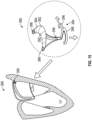
- Figs. 12A-12D the method of clip 192 and pledget 194 placement is shown.
- the clip 192 and pledget 194 are initially loaded on the hypotube 196.
- a guide suture 210 extends in a loop from the hypotube 196.
- the guide suture 210 can engage the anchor suture 158.
- the anchor suture 158 is connected to the anchor 146 as shown in Fig. 12A .
- the hypotube 196 is retracted into the clip delivery catheter 116, as shown by the upward arrow in Fig. 12B .
- the distal tip of the clip delivery catheter 116 pushes downward on the clip 192, as shown by the downward arrow in Fig. 12B .
- the clip 192 presses against the pledget 194 and both the clip 192 and the pledget 194 are pressed downward by the clip delivery catheter 116.
- the clip 192 and the pledget 194 are advanced along the anchor suture 158.
- the compression force of the clip 192 on the anchor suture 158 locks the clip 192 on the anchor suture 158.
- the pledget 194 is prevented from translation along the anchor suture 158 by the locking of the clip 192.
- the second hypotube 204 is pressed downward on the clip 192 and the pledget 194 instead of, or in addition to, the tip of the clip delivery catheter 116.
- the guide suture 210 can extend from the hypotube 196.
- the hypotube 196 is crimped over the guide suture 210. This crimping allows easy introduction of the clip 192 and/or the pledget 194 over the guide suture 210. This crimping also ensures a proper connection between the hypotube 196 and the anchor 146. After the clip 192 and/or the pledget 194 is locked, the guide suture 210 can be cut and retracted through the clip delivery catheter 116, as shown in Fig. 12D .
- the aforementioned method can be performed by a physician.
- a manufacturer can provide one, some or all of the following: the clip 192, the pledget 194, the hypotube 196, the second hypotube 204, the anchor 146, the anchor suture 158, the guide suture 210, and clip delivery catheter 116.
- the manufacture provides a kit containing some or all of the devices previously described.
- the manufacturer provides instructions for use of the system including one or more of the following steps, or any step previously described or inherent in the drawings.
- the steps may include: initially loading the clip 192 and/or the pledget 194 on the hypotube 196; extending the guide suture 210 from the hypotube 196; engaging the guide suture 210 to the anchor suture 158; connecting the anchor suture 158 to the anchor 146; retracting the hypotube 196 into the clip delivery catheter 116; pressing the distal tip of the clip delivery catheter 116 downward on the clip 192; pressing the clip 192 against the pledget 194; pressing both the clip 192 and the pledget 194 downward; and advancing the clip 192 and the pledget 194 along the anchor suture 158.
- the steps may include: crimping the hypotube 196 over the guide suture 210; cutting the guide suture 210 after the clip 192 is locked; and retracting the guide suture 210 through the clip delivery catheter 116.
- These instructions can be written, oral, or implied.
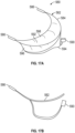
- the coaptation assistance device 280 can be substantially similar to the coaptation assistance device 80, 180 described herein.
- the coaptation assistance device 280 can include frame 282 configured to provide structural support to the coaptation assistance device 280.
- the frame 282 is collapsible to fit within a delivery catheter, as described herein.
- the frame 282 defines a superior edge 284.
- the frame 282 can include anchor eyelets 286 configured to accept an anchor, such as anchor 146 or other trigonal anchors.
- the eyelets 286 can be integrated into the surface of the coaptation assistance device 280 or coupled to the coaptation assistance device 280 by any mechanism known in the art.
- the eyelets 286 correspond to the region of the coaptation assistance device 280 that may be secured to the anterior and posterior fibrous trigones 56, 60.
- the trigones 56, 60 are located approximately 1-10 mm lateral or medial to their respective commissures 50, 52, and about 1-10 mm more anterior than the commissures 50, 52.
- different anchor arrangements may connect the superior edge 284 of the coaptation assistance device 280 can to an anchor, such as anchor 146.
- the superior edge 284 can include a hub (not shown) for an anchor to extent or a tether (not shown) connecting the anchor or a hub to the superior edge 284.
- the medial end of a tether or the hub is connected to the eyelet 286.
- Alternate engagement means are contemplated for connecting the coaptation assistance device 280 to each anchor, including the eyelets 286 and hubs (not shown), but also including other connection means such as, for example, sutures, staples, adhesive or clips.
- the anchors may form an integrated part of the device.
- both anchors inserted within the eyelet 286 are helical anchors.
- the coaptation assistance device 280 comprises a body 290.
- the body 290 comprises a first surface 292 disposed toward a mal-coapting native leaflet, in the instance of a mitral valve 20, the posterior leaflet 32 and a second surface 294 which may be disposed toward the anterior leaflet 30.
- the first and second surfaces 292, 294 can be considered cooptation surface.
- the coaptation assistance device 280 can have a geometry which permits it to traverse the mitral valve 20 between attachment sites in the left atrium 10 and/or the left ventricle 14, to provide a coaptation surface 294 for the anterior leaflet 30 to coapt against, and attach to the left atrium 10 or annulus 36 such that it effectively seals off the posterior leaflet 32.
- the coaptation assistance device 280 replaces the posterior leaflet 32.
- the coaptation surface 292, 294 of the coaptation assistance device 280 passes superiorly and radially inwardly from the superior edge 284, before passing distally, in a longitudinal direction perpendicular to the valve plane, or radially inwardly or outwardly with respect to the valve plane.
- the first surface 292 and the second surface 294 of the coaptation assistance device 280 further comprise a covering comprised of ePTFE, polyurethane foam, polycarbonate foam, biologic tissue such as porcine pericardium, or silicone.
- the coaptation assistance device 280 may include one or a plurality of anchors, such as anchor 146, to stabilize the coaptation assistance device 280.
- the coaptation assistance device 280 can also have a ventricular anchor 296 (e.g., ribbons described herein).
- the ventricular anchor 296 engages the area under the posterior leaflet 32.
- the atrial and/or ventricular anchors optionally providing redundant fixation.
- the anchors may include a plurality of barbs for acute fixation to the surrounding tissue.
- the anchors may comprise a plurality of helixes, clips, harpoon or barb-shaped anchors, or the like, appropriate for screwing or engaging the annulus 36 of the mitral valve 20, tissues of the ventricle, and/or other tissues of the atrium, or the atrial or ventricular anchors may attach to the tissue by welding using RF or other energy delivered via the elongate anchor coupling body.
- a ventricular anchor 296 may be included in the form of a tether or other attachment means extending from the valve 20 thru the ventricle septum to the right ventricle 16, or through the apex into the epicardium or pericardium, which may be secured from outside the heart in and combined endo/epi procedure.
- helical anchors may comprise bio-inert materials such as Platinum/Ir, a Nitinol alloy, and/or stainless steel.
- a transseptal method for treatment of MR can include gaining access to the left atrium 10 via the transseptal sheath 110. Access to the femoral vein may be obtained using the Seldinger technique. From the femoral vein, access can then be obtained via the right atrium 12 to the left atrium 10 by a transseptal procedure.
- a variety of conventional transseptal access techniques and structures may be employed, so that the various imaging, guidewire advancement, septal penetration, and contrast injection or other positioning verification steps need not be detailed herein.
- a guidewire is used to advance the anchors 146 to the desired location.
- a posteromedial trigonal anchor 146 is placed and an anterolateral trigonal anchor 146 is placed using the guidewire.
- each trigonal anchor 146 comprises at least one guidewire or rail 160 such that the coaptation assistance device 280 can be advanced over the rails 160.
- the rails 160 advance through a portion of the coaptation assistance device 280 and through the transseptal catheter 110.
- the rails 160 extend through eyelets 286.
- the coaptation assistance device 280 is collapsed inside the anchor delivery catheter 112.
- the coaptation assistance device 280 is collapsed and delivered through the transseptal catheter 110 over the rails 160.
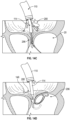
- the coaptation assistance device 280 is advanced over two rails 160 as shown by the arrows in Fig. 14C .
- the rails 160 facilitate placement of the coaptation assistance device 280.
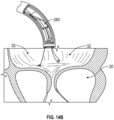
- the coaptation assistance device 280 exits the implant delivery catheter 114, allowing the coaptation assistance device 280 to be exposed and expanded.
- the coaptation assistance device 280 can be delivered by the implant delivery catheter 114 and may be capable of expanding from a smaller profile to a larger profile to dimensions appropriate for placement in between the valve's native leaflets 30, 32.
- the coaptation assistance device 280 is expanded as it is exposed from the tip of the implant delivery catheter 114 as shown. In some embodiments, the implant delivery catheter 114 is pulled back to expose the coaptation assistance device 280.
- the coaptation assistance device 280 is advanced over the posterior leaflet 32.
- the coaptation assistance device 280 can extend through the mitral valve 20 into the left ventricle 14.
- the coaptation assistance device 280 may have a ventricular anchor 296 that is expanded to attach the coaptation assistance device 280 to ventricular tissue.
- the ventricular anchor 296 of the coaptation assistance device 280 can be delivered by the implant delivery catheter 114.
- the implant delivery catheter 114 is retracted into the transseptal catheter 110.
- the ventricular anchor 296 of the coaptation assistance device 280 is released and can assume a curved shape as shown.
- the coaptation assistance device 280 is locked on the anchors 146 by one or more clips 192 and/or pledget 194, as shown in Fig. 14D .
- the catheter delivery system 106 is removed.
- the rails 160 are also removed.
- a manufacturer can provide one, some or all of the following: coaptation assistance device 280, transseptal sheath 110, anchor delivery catheter 112, implant delivery catheter 114, and clip delivery catheter 116.
- the manufacturer provides a kit containing some or all of the devices previously described.
- the manufacturer provides instructions for use of the system including one or more of the following steps, or any step previously described or inherent in the drawings.
- the steps may include: gaining access to the left atrium 10 via a transseptal sheath 110; gaining access to the femoral vein via the Seldinger technique; gaining access via the right atrium 12 to the left atrium 10 by a transseptal procedure, utilizing a variety of conventional transseptal access techniques and structures.
- the steps may include: positioning the transseptal sheath 110 within the left atrium 10; deploying an anchor delivery catheter 112 through the transseptal sheath 110 and into the left atrium 10; bringing the distal end of the anchor delivery catheter 112 into alignment and/or engagement with candidate locations for deployment of an anchor 146; and determining if the candidate site is suitable.
- the steps may include: collapsing the coaptation assistance device 280 inside the implant delivery catheter 114; delivering the coaptation assistance device 280 through the transseptal sheath 110 over the rails 160; expanding the coaptation assistance device 280 as it exits the implant delivery catheter 114; and retracting the implant delivery catheter 114.
- the steps may include: delivering and/or engaging the anchor 146, which may be the first trigonal anchor; deploying a raid 160 attached to each anchor 146; advancing the coaptation assistance device 280 over the rail 160; delivering and/or engaging the second anchor 146, which may be the second trigonal anchor; deploying the rail 160 attached to the second anchor; advancing the coaptation assistance device 180 over the rails 160 delivering and/or engaging the second anchor 146; facilitating placement of the coaptation assistance device 180; and positioning the coaptation assistance device 180 over the posterior leaflet 32.
- the steps may include: extending the coaptation assistance device 180 through the mitral valve 20 into the left ventricle 14; expanding a ventricular anchor 296 of the coaptation assistance device 180; locking the coaptation assistance device 180 on the anchors 146 by one or more clips 192 and/or pledgets 194; and removing the catheter delivery system 106.
- These instructions can be written, oral, or implied.
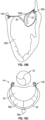
- the coaptation assistance device 380 can be substantially similar to the coaptation assistance device 80, 180, 280 described herein.
- the coaptation assistance device 380 can include frame 382 configured to provide structural support to the coaptation assistance device 380.
- the frame 382 is collapsible to fit within a delivery catheter, such as implant delivery catheter 114.
- the frame 382 defines a superior edge 384.
- the frame 382 can include anchor eyelets 386 configured to accept an anchor, such as anchor 146.
- the eyelets 386 are configured to accept a commissure anchor 390.
- Commissure anchor locations are provided, such as at lateral ends of an arcuate body portion of the coaptation assistance device 380 as shown.
- the commissure anchor 390 is substantially similar or identical to the anchor 146 described herein.
- the eyelets 386 can be integrated into the surface of the coaptation assistance device 380 or coupled to the coaptation assistance device 380 by any mechanism known in the art.
- the eyelets 386 correspond to the region of the coaptation assistance device 280 that may be secured to the lateral commissures 50, 52.
- different anchor arrangements may connect the frame 382 of the coaptation assistance device 280 to anchors.
- different anchor arrangements may connect the frame 282 and/or edge of the coaptation assistance device 380 to the corresponding anatomic structure.
- one or more of the commissure anchors 390 are helical anchors, as shown. There are many possible configurations for anchoring, compositions of anchors, and designs as, for example, previously described.
- the coaptation assistance device 380 comprises a body 392, which may be configured to permit relatively normal circulation of blood in the ventricular chamber.
- the body 392 may be elongate and narrow between the anterior and posterior surfaces, taking up minimal space and allowing movement of blood from one side to another and past both lateral aspects of the coaptation assistance device 380.
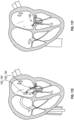
- the coaptation assistance device 380 may include one or a plurality of ventricular anchors 394.
- the atrial anchors and ventricular anchors can optionally provide redundant fixation.
- the atrial anchors may include a plurality of barbs for acute fixation to the surrounding tissue.
- the atrial anchors may comprise a plurality of helixes, clips, harpoon or barb-shaped anchors, or the like, appropriate for engaging tissues of the ventricle.
- the ventricular anchor can comprise two ribbons 396 that rest against the wall of the left ventricle 14. While two ribbons 396 are shown, in some embodiments one or more ribbons 396 are used (e.g.,. one, two, three, four etc.).
- ventricular anchors 394 may comprise bio-inert materials such as, for example, Platinum/Ir, a Nitinol alloy, and/or stainless steel.
- the ribbons 396 comprise NiTi.
- the ribbons 396 have a pre-determined curve. The material selection combined with the selected shape provides a ventricular anchor 394 that is spring loaded. In some embodiments, the spring loaded ribbons 396 engage tissues of the left ventricle 14 as shown. Each ribbon 396 can form, for example, a generally U-shaped configuration.
- the ribbons 396 function as anchors and resist movement of the coaptation assistance device 380.
- the ribbons 396 together can form a generally W-shaped configuration.
- the ribbons 396 comprise a rounded surface configured to abut tissue.
- the anchors abut tissue and can exert a force on the tissue to stabilize the coaptation assistance device 380, but do not penetrate through one or more tissue layers, e.g., the endocardium or myocardium.
- the anchors include a pair of arms with a bias that when in an unstressed configuration can clip onto a portion of the ventricular wall to stabilize the coaptation assistance device, such as in a non-traumatic manner with respect to the ventricular wall.
- the size and shape of the ribbons can be determined based upon the dimensions of the left ventricle 14, and the left ventricle wall which the ribbons 396 may abut.
- the ribbons 396 can be generally parallel to the base of the posterior leaflet 32. Other shapes for the ribbons 396 are contemplated.
- the coaptation assistance device 380 is collapsed inside the delivery catheter, such as implant delivery catheter 114.
- the spring loaded ribbons 396 are capable of being collapsed within the delivery catheter. Upon exiting the catheter, the spring loaded ribbons 396 rapidly expand into the preformed shape.
- the ribbons 396 are provided for ventricular attachment.
- the ribbons 396 allow for very rapid attachment of the coaptation assistance device 380 to the tissue, since the ribbons 396 do not rely on annular sutures and do not require tying knots.
- the deployment of the ribbons 396 can be faster than engaging a helical anchor, for instance.
- the coaptation assistance device 480 can be substantially similar to the coaptation assistance device 80, 180, 280, 380 described herein.
- the coaptation assistance device 480 can include frame 482 configured to provide structural support to the coaptation assistance device 480.
- the frame 482 is collapsible to fit within a delivery catheter, such as implant delivery catheter 114.
- the frame 482 defines a superior edge 484.
- the frame 482 can include anchor eyelets 486 configured to accept an anchor, such as anchor 146.
- the eyelets 486 are configured to accept an anchor 490.
- a plurality of locations for eyelets 486 are provided as shown in Fig. 16 .
- different anchor arrangements may connect the edge of the coaptation assistance device 480 to the corresponding anatomic structure.
- the anchors 490 are helical anchors, as shown. There are many possible configurations for anchoring means, compositions of anchors, and designs for anchoring means.
- the anchor 490 can be substantially similar or identical to anchor 146.
- the coaptation assistance device 480 may include one or a plurality of atrial anchors 490 and ventricular anchors 494, with the anchors optionally providing redundant fixation.
- the atrial anchors 490 may comprise a plurality of helixes, clips, harpoon or barb-shaped anchors, or the like, appropriate for engaging tissues of the ventricle.
- the atrial anchors 490 may extend through the posterior leaflet as shown.
- the ventricular anchor 494 comprises a plurality of, e.g., three spring-loaded clips or ribbons 496 configured to engage at least a portion of a mitral valve 20, e.g., a portion of posterior leaflet 32 resides in between the ribbons 496 and the body 482.
- a clip or ribbon can has a bias (e.g., by virtue of its shape memory properties) such that one, two, or more surfaces exert a force, such as a compressive force, on a body structure such as a valve leaflet as shown sufficient to anchor the implant in place.
- a bias e.g., by virtue of its shape memory properties
- a first portion of a clip can apply a force against a first surface of a valve leaflet as illustrated
- a second portion of the clip can apply a force or rest against a second side of the leaflet, the second side of the leaflet opposite the first side of the leaflet.
- three ribbons 496 are shown, in some embodiments any number of ribbons 496 can be used (e.g., one, two, three, four, etc.).
- This position may provide stability of the coaptation assistance device 480 and/or the implant base 498. This position may not require additional anchoring of the coaptation assistance device to the ventricle 14 or elsewhere.
- ribbons 496 may comprise, e.g., bio-inert materials such as Platinum/Ir, a Nitinol alloy, and/or stainless steel.
- the ribbons 496 comprise NiTi.
- the ribbons 496 have a pre-determined curve. The material selection combined with the selected shape provides a ventricular anchor 496 that is spring loaded. The ribbons 496 rest against the posterior leaflet, as shown. In some embodiments, the spring loaded ribbons 496 engage other tissues of the mitral valve.
- Each ribbon 496 can form a generally S-shaped configuration.
- the ribbons 496 function as anchors and resist movement of the coaptation assistance device 480.
- the ribbons 496 comprise a rounded surface configured to abut tissue.
- the size and shape of the ribbons 496 can be determined based upon the dimensions of the posterior leaflet 32 which the ribbons 496 may abut.
- the ribbons 496 can be generally parallel to the tip of the posterior leaflets 32. Other shapes for the ribbons 496 are contemplated.
- the coaptation assistance device 480 is collapsed inside the delivery catheter.
- the spring loaded ribbons 496 are capable of being collapsed within the delivery catheter, such as implant delivery catheter 114. Upon exiting the catheter, the spring loaded ribbons 496 rapidly expand into the preformed shape.
- the ribbons 496 are provided for ventricular attachment.
- the ribbons 496 allow for very rapid attachment of the coaptation assistance device 480 to the tissue, since the ribbons 496 do not rely on annular sutures and do not require tying knots.
- the deployment of the ribbons 496 can be faster than engaging a helical anchor, for instance.
- the ribbons 500 are provided.
- the ribbons 500 extend to the base of the posterior leaflet 32 and align with the anchor 490.
- the anchor 490 positioned on the posterior leaflet 32 may penetrate the leaflet 32 and connect with the ribbon 500.
- anchors 490 positioned on the ribbons 500 may penetrate the posterior leaflet from the opposite direction.
- the anchor 490 can engage the upper, left atrium side of the coaptation assistance device 480 and the ribbons 500 located in the left ventricle. This configuration may improve the stability of the coaptation assistance device 480.
- Each ribbon 500 can form a generally L-shaped configuration.
- the ribbons 500 comprise a rounded surface configured to abut the ventricular side of the posterior leaflet 32.
- the clips or ribbons as disclosed in connection with various embodiments herein can be advantageously utilized with a wide variety of cardiac implants not limited to the coaptation assistance devices disclosed herein.
- the clips or ribbons can be operably connected to replacement heart valves such as mitral or aortic valves, for example, for anchoring and stabilization.
- the clips or ribbons can exert a force to clip or otherwise attach onto one or more native valve leaflets, in order to anchor a replacement heart valve in the valve annulus.
- the eyelets 586 are configured to accept a trigonal anchor such as anchor 146.
- the eyelets 586 correspond to the region of the coaptation assistance device 580 that may be secured to the anterior and posterior fibrous trigones 56, 60.
- the coaptation assistance device 580 comprises a ventricular anchor hub 590.
- the hub 590 provides an attachment structure for a ventricular anchor 594.
- the coaptation assistance device 580 comprises a body 592.
- the body 592 comprises a first surface 596 disposed toward a mal-coapting native leaflet, in the instance of a mitral valve 20, the posterior leaflet 32 and a second surface 598 which may be disposed toward the anterior leaflet 30.
- the first and second surfaces 596, 598 can be considered cooptation surface.
- the coaptation assistance device 580 can have a geometry which permits it to traverse the mitral valve 20 between attachment sites in the left atrium 10 and left ventricle 14, to provide a coaptation surfaces 598 for the anterior leaflet 30 to coapt against, and attach to the atrium 10 or annulus 36 such that it effectively seals off the posterior leaflet 32. In the instance that the posterior leaflet 32 is or has been removed, the coaptation assistance device 580 replaces the posterior leaflet 32.
- the coaptation surface 598 of the coaptation enhancement element passes superiorly and radially inwardly from the superior edge, before passing distally, in a longitudinal direction perpendicular to the valve plane, or radially inwardly or outwardly with respect to the valve plane.
- anterior surface 598 and posterior surface 596 of the coaptation assist device 580 further comprise a covering comprised of ePTFE, polyurethane foam, polycarbonate foam, biologic tissue such as porcine pericardium, or silicone.
- the frame 582 is shown, with frame connecting the eyelets 586. Other frame elements may be incorporated into the coaptation assistance device 580.
- the frame 582 may be shaped in any number of ways to assist in maintaining the desired shape and curvature of the coaptation assistance device 580.
- the frame can be made of Nitinol, stainless steel, polymer or other appropriate materials, can substantially assist in maintain the geometry of the coaptation assistance device 580, permitting choice of any of a wide variety of covering materials best suited for long term implantation in the heart and for coaptation against the anterior leaflet 30.
- the coaptation assistance device 580 may include one or a plurality of anchors to stabilize the coaptation assistance device 580, with the anchors optionally providing redundant fixation.
- the anchors may include a plurality of barbs for acute fixation to the surrounding tissue.
- the anchors may comprise a plurality of helixes, clips, harpoon or barb-shaped anchors, or the like, appropriate for screwing or engaging into the annulus of the mitral valve 20, tissues of the left ventricle 14, and/or other tissues of the left atrium 10.
- the anchors may attach to the tissue by welding using RF or other energy delivered via the elongate anchor coupling body.
- a delivery catheter 600 is advanced into the left atrium 10.
- the delivery catheter 600 can be substantially similar to implant delivery catheter 114.
- the delivery catheter 600 may be advanced through the outer transseptal sheath 110 and into the left atrium 10.
- Fig. 18A shows an embodiment of the delivery catheter 600.
- the delivery catheter 600 may include a shaft 602 made of a polymer for example.
- the shaft 602 is a braid or coil reinforced polymer shaft.
- the shaft 602 has multiple durometers.
- the delivery catheter 600 comprises an actively deflectable tip 604 to facilitate navigation of one or more anchors 594 to the anchoring sites.
- the deflectable tip 604 can access the site under the posterior leaflet.
- the delivery catheter 600 may include a deflection knob 606 to control the deflectable tip 604.
- the delivery catheter may include a drive shaft 610.
- the drive shaft 610 has a feature at the tip to engage with and allow transmission of torque to the anchor 594.
- the drive shaft 610 is flexible.
- the drive shaft 610 is capable of being advanced or retracted.
- the delivery catheter 600 may include a knob 612 that is connected to the drive shaft 610.
- the knob 612 is internally connected to the drive shaft 610 thereby allowing transmission of torque to the anchor 594 when the knob 612 is rotated. This enables simple manipulation of the anchor position and torque.
- the coaptation assistance device 580 can be delivered by the delivery catheter 600 and may be capable of expanding from a smaller profile to a larger profile to dimensions appropriate for placement in between the valve's native leaflets 30, 32.
- the coaptation assistance device 580 is expanded as it is exposed from the tip of the delivery catheter 600. In some embodiments, the delivery catheter 600 is pulled back to expose the coaptation assistance device 580.
- the delivery catheter 600 may further include a control handle 614 to manipulate the coaptation assistance device 580 and/or, to manipulate the docking and undocking of the coaptation assistance device 580 with the delivery catheter 600 and/or to facilitate placement of the coaptation assistance device 580.
- the distal end of the delivery catheter 600 moves within the left atrium 10 by manipulating the control handle 614 and by articulating the actuator of deflection knob 612 so as to selectively bend the deflectable tip 604 and/or the distal end of the delivery catheter 600.
- the deflectable tip 604 and/or the distal end of the delivery catheter 600 can be brought into alignment and/or engagement with candidate locations for deployment of the anchor 594.
- the deflectable tip 604 and/or distal end of the delivery catheter 600 can be deflected to access the site under the posterior leaflet 32.
- the distal end of the delivery catheter 600 is brought into alignment with the wall of the left ventricle 14 to facilitate placement of the ventricle hub 590 and/or ventricle anchor 594.
- the coaptation assistance device 580 is anchored and the delivery catheter 600 is removed.
- the coaptation surface 598 is placed between the anterior leaflet 30 and the posterior leaflet 32.
- the ventricular anchor 594 and the trigonal anchors 146 are secured.
- the aforementioned method can be performed by a physician.
- the manufacturer can provide one, some or all of the following: coaptation assistance device 580, delivery catheter 600, trigonal anchor 146, and ventricular anchor 594.
- the manufacturer provides a kit containing some or all of the devices previously described.
- the manufacturer provides instructions for use of the system including one or more of the following steps, or any step previously described or inherent in the drawings.
- the steps may include: positioning the delivery catheter 600 within the left atrium 10; bringing the deflectable tip 604 and/or the distal end of the delivery catheter 600 into alignment and/or engagement with candidate locations for deployment of an anchor; and determining if the candidate site is suitable.
- the steps may include: delivering and/or engaging the first trigonal anchor 146; delivering and/or engaging the second trigonal anchor 146; facilitating placement of the coaptation assistance device 580; and positioning the coaptation assistance device 580 over the posterior leaflet.
- the steps may include: extending the coaptation assistance device 580 through the mitral valve 20 into the left ventricle 14; locking the coaptation assistance device 580 on the trigonal anchors 146 by one or more clips 192 and/or pledgets 194; and removing the catheter delivery system.
- These instructions can be written, oral, or implied. It should be understood, however, that the invention is not to be limited to the particular forms disclosed, but to the contrary, the invention is to cover all modifications, equivalents, and alternatives falling within the scope of the appended claims. Language such as “up to,” “at least,” “greater than,” “less than,” “between,” and the like includes the number recited.
- Numbers preceded by a term such as “approximately”, “about”, and “substantially” as used herein include the recited numbers, and also represent an amount close to the stated amount that still performs a desired function or achieves a desired result.
- the terms “approximately”, “about”, and “substantially” may refer to an amount that is within less than 10% of, within less than 5% of, within less than 1% of, within less than 0.1% of, and within less than 0.01% of the stated amount.
Landscapes
- Health & Medical Sciences (AREA)
- Cardiology (AREA)
- Life Sciences & Earth Sciences (AREA)
- Engineering & Computer Science (AREA)
- General Health & Medical Sciences (AREA)
- Biomedical Technology (AREA)
- Heart & Thoracic Surgery (AREA)
- Veterinary Medicine (AREA)
- Public Health (AREA)
- Animal Behavior & Ethology (AREA)
- Vascular Medicine (AREA)
- Oral & Maxillofacial Surgery (AREA)
- Transplantation (AREA)
- Surgery (AREA)
- Rheumatology (AREA)
- Nuclear Medicine, Radiotherapy & Molecular Imaging (AREA)
- Medical Informatics (AREA)
- Molecular Biology (AREA)
- Prostheses (AREA)
Applications Claiming Priority (3)
| Application Number | Priority Date | Filing Date | Title |
|---|---|---|---|
| US201361895647P | 2013-10-25 | 2013-10-25 | |
| US14/313,975 US10166098B2 (en) | 2013-10-25 | 2014-06-24 | Systems and methods for transcatheter treatment of valve regurgitation |
| PCT/US2014/061901 WO2015061533A1 (en) | 2013-10-25 | 2014-10-23 | Systems and methods for transcatheter treatment of valve regurgitation |
Publications (3)
| Publication Number | Publication Date |
|---|---|
| EP3060175A1 EP3060175A1 (en) | 2016-08-31 |
| EP3060175A4 EP3060175A4 (en) | 2017-07-05 |
| EP3060175B1 true EP3060175B1 (en) | 2025-04-23 |
Family
ID=52993541
Family Applications (1)
| Application Number | Title | Priority Date | Filing Date |
|---|---|---|---|
| EP14856738.1A Active EP3060175B1 (en) | 2013-10-25 | 2014-10-23 | Implant for transcatheter treatment of valve regurgitation |
Country Status (7)
| Country | Link |
|---|---|
| US (5) | US10166098B2 (enExample) |
| EP (1) | EP3060175B1 (enExample) |
| JP (3) | JP6706200B2 (enExample) |
| CN (2) | CN106061437B (enExample) |
| CA (1) | CA2934182C (enExample) |
| ES (1) | ES3035969T3 (enExample) |
| WO (1) | WO2015061533A1 (enExample) |
Families Citing this family (136)
| Publication number | Priority date | Publication date | Assignee | Title |
|---|---|---|---|---|
| US12370044B2 (en) | 2009-10-06 | 2025-07-29 | Reniva, Inc. | Systems and methods for treating luminal valves |
| EP2654624B1 (en) | 2010-12-23 | 2023-10-04 | Twelve, Inc. | System for mitral valve repair and replacement |
| US8845717B2 (en) | 2011-01-28 | 2014-09-30 | Middle Park Medical, Inc. | Coaptation enhancement implant, system, and method |
| US8888843B2 (en) | 2011-01-28 | 2014-11-18 | Middle Peak Medical, Inc. | Device, system, and method for transcatheter treatment of valve regurgitation |
| EP2723273B1 (en) | 2011-06-21 | 2021-10-27 | Twelve, Inc. | Prosthetic heart valve devices |
| US9763780B2 (en) | 2011-10-19 | 2017-09-19 | Twelve, Inc. | Devices, systems and methods for heart valve replacement |
| JP6151705B2 (ja) | 2011-10-19 | 2017-06-21 | トゥエルヴ, インコーポレイテッド | 心臓弁置換のためのデバイス、システムおよび方法 |
| US9039757B2 (en) | 2011-10-19 | 2015-05-26 | Twelve, Inc. | Prosthetic heart valve devices, prosthetic mitral valves and associated systems and methods |
| EP3984500B1 (en) | 2011-10-19 | 2024-07-17 | Twelve, Inc. | Prosthetic heart valve devices |
| US11202704B2 (en) | 2011-10-19 | 2021-12-21 | Twelve, Inc. | Prosthetic heart valve devices, prosthetic mitral valves and associated systems and methods |
| US9655722B2 (en) | 2011-10-19 | 2017-05-23 | Twelve, Inc. | Prosthetic heart valve devices, prosthetic mitral valves and associated systems and methods |
| US10076414B2 (en) * | 2012-02-13 | 2018-09-18 | Mitraspan, Inc. | Method and apparatus for repairing a mitral valve |
| US9579198B2 (en) | 2012-03-01 | 2017-02-28 | Twelve, Inc. | Hydraulic delivery systems for prosthetic heart valve devices and associated methods |
| US20240285405A1 (en) * | 2012-11-07 | 2024-08-29 | Transmural Systems Llc | Devices, systems and methods for repairing lumenal systems |
| CA2910948C (en) | 2013-05-20 | 2020-12-29 | Twelve, Inc. | Implantable heart valve devices, mitral valve repair devices and associated systems and methods |
| EP3007652A2 (en) * | 2013-06-14 | 2016-04-20 | Hazu GmbH | Method and device for treatment of valve regurgitation |
| US10166098B2 (en) | 2013-10-25 | 2019-01-01 | Middle Peak Medical, Inc. | Systems and methods for transcatheter treatment of valve regurgitation |
| JP2016538076A (ja) * | 2013-11-28 | 2016-12-08 | ムバルブ・テクノロジーズ・リミテッド | 改善された耐疲労性を有する安定化要素を備える心臓内装置 |
| US10390943B2 (en) | 2014-03-17 | 2019-08-27 | Evalve, Inc. | Double orifice device for transcatheter mitral valve replacement |
| US12350147B2 (en) | 2014-03-29 | 2025-07-08 | Corvivo Cardiovascular, Inc. | Adaptable prosthetic tissue valves |
| ES2908178T5 (en) | 2014-06-18 | 2025-03-03 | Polares Medical Inc | Mitral valve implants for the treatment of valvular regurgitation |
| WO2015200497A1 (en) | 2014-06-24 | 2015-12-30 | Middle Peak Medical, Inc. | Systems and methods for anchoring an implant |
| FR3027212A1 (fr) | 2014-10-16 | 2016-04-22 | Seguin Jacques | Implant intervalvulaire pour valve mitrale |
| US10231827B2 (en) | 2015-03-18 | 2019-03-19 | Medtronic Vascular, Inc. | Valve prostheses having an integral centering mechanism and methods of use thereof |
| US9629720B2 (en) | 2015-05-04 | 2017-04-25 | Jacques Seguin | Apparatus and methods for treating cardiac valve regurgitation |
| US10238490B2 (en) | 2015-08-21 | 2019-03-26 | Twelve, Inc. | Implant heart valve devices, mitral valve repair devices and associated systems and methods |
| US10531956B2 (en) * | 2015-09-03 | 2020-01-14 | Vesalous Cardiovascular Inc. | Apparatus for repairing heart valves and method of use thereof |
| US9592121B1 (en) | 2015-11-06 | 2017-03-14 | Middle Peak Medical, Inc. | Device, system, and method for transcatheter treatment of valvular regurgitation |
| US10357365B2 (en) * | 2016-03-07 | 2019-07-23 | Serca Biomedical, LLC | Annuloplasty repair devices, systems and methods |
| JP7015609B2 (ja) * | 2016-03-08 | 2022-02-03 | スートラ メディカル,インク. | 心臓弁膜置換システムおよびその方法 |
| WO2019241777A1 (en) * | 2018-06-15 | 2019-12-19 | Dura Llc | Heart valve leaflet replacement device and multi-stage, multi-lumen heart valve delivery system and method for the same |
| US20210212824A1 (en) * | 2016-03-08 | 2021-07-15 | Dura Llc | Heart valve leaflet replacement devices and multi-stage, multi-lumen heart valve delivery systems and method for use |
| CN105997304B (zh) * | 2016-04-29 | 2017-11-28 | 肖书娜 | 心脏瓣膜环缩装置 |
| US10265172B2 (en) | 2016-04-29 | 2019-04-23 | Medtronic Vascular, Inc. | Prosthetic heart valve devices with tethered anchors and associated systems and methods |
| US20200146854A1 (en) | 2016-05-16 | 2020-05-14 | Elixir Medical Corporation | Methods and devices for heart valve repair |
| US20170354500A1 (en) * | 2016-06-08 | 2017-12-14 | Cook Medical Technologies Llc | Mitral prolapse valve restrictor |
| US10945842B2 (en) * | 2016-08-04 | 2021-03-16 | Evalve, Inc. | Annular augmentation device for cardiac valve repair |
| US12011352B2 (en) | 2016-08-15 | 2024-06-18 | The Cleveland Clinic Foundation | Apparatuses and methods for at least partially supporting a valve leaflet of a regurgitant heart valve |
| EP3496665B1 (en) * | 2016-08-15 | 2023-11-15 | The Cleveland Clinic Foundation | Apparatuses for at least partially supporting a valve leaflet of a regurgitant heart valve |
| US10493248B2 (en) | 2016-11-09 | 2019-12-03 | Medtronic Vascular, Inc. | Chordae tendineae management devices for use with a valve prosthesis delivery system and methods of use thereof |
| US10368988B2 (en) | 2016-11-09 | 2019-08-06 | Medtronic Vascular, Inc. | Valve delivery system having an integral displacement component for managing chordae tendineae in situ and methods of use thereof |
| US10363138B2 (en) | 2016-11-09 | 2019-07-30 | Evalve, Inc. | Devices for adjusting the curvature of cardiac valve structures |
| US10426616B2 (en) | 2016-11-17 | 2019-10-01 | Evalve, Inc. | Cardiac implant delivery system |
| WO2018119192A1 (en) | 2016-12-21 | 2018-06-28 | TriFlo Cardiovascular Inc. | Heart valve support device and methods for making and using the same |
| US11419719B2 (en) | 2017-02-06 | 2022-08-23 | Mtex Cardio Ag | Methods and systems for assisting or repairing prosthetic cardiac valves |
| US10675017B2 (en) | 2017-02-07 | 2020-06-09 | Edwards Lifesciences Corporation | Transcatheter heart valve leaflet plication |
| US20190358034A1 (en) * | 2017-02-17 | 2019-11-28 | Mitrapex, Inc. | Artificial heart valve |
| EP3372198B1 (en) * | 2017-03-06 | 2019-06-19 | AVVie GmbH | Implant for improving coaptation of an atrioventricular valve |
| US10653524B2 (en) | 2017-03-13 | 2020-05-19 | Polares Medical Inc. | Device, system, and method for transcatheter treatment of valvular regurgitation |
| US10478303B2 (en) | 2017-03-13 | 2019-11-19 | Polares Medical Inc. | Device, system, and method for transcatheter treatment of valvular regurgitation |
| CN114587711A (zh) * | 2017-03-13 | 2022-06-07 | 宝来瑞斯医疗有限公司 | 用于经导管治疗瓣膜返流的装置、系统和方法 |
| CN110603007A (zh) | 2017-03-27 | 2019-12-20 | 维维泰生物医药有限公司 | 用于经导管二尖瓣和三尖瓣修复的装置和方法 |
| US10716668B2 (en) | 2017-04-05 | 2020-07-21 | Medtronic, Inc. | Delivery system with anchoring nosecone and method of delivery |
| US10575950B2 (en) | 2017-04-18 | 2020-03-03 | Twelve, Inc. | Hydraulic systems for delivering prosthetic heart valve devices and associated methods |
| US10702378B2 (en) | 2017-04-18 | 2020-07-07 | Twelve, Inc. | Prosthetic heart valve device and associated systems and methods |
| US10433961B2 (en) | 2017-04-18 | 2019-10-08 | Twelve, Inc. | Delivery systems with tethers for prosthetic heart valve devices and associated methods |
| EP4005500A1 (en) | 2017-04-20 | 2022-06-01 | Medtronic, Inc. | Stabilization of a transseptal delivery device |
| US10792151B2 (en) | 2017-05-11 | 2020-10-06 | Twelve, Inc. | Delivery systems for delivering prosthetic heart valve devices and associated methods |
| US10722362B2 (en) * | 2017-05-22 | 2020-07-28 | Edwards Lifesciences Corporation | Adjustable and reversible locking mechanism for catheter-delivered implant |
| US10583685B2 (en) * | 2017-06-01 | 2020-03-10 | Brenda A. Heim | Sculpture making system |
| US10646338B2 (en) | 2017-06-02 | 2020-05-12 | Twelve, Inc. | Delivery systems with telescoping capsules for deploying prosthetic heart valve devices and associated methods |
| US10709591B2 (en) | 2017-06-06 | 2020-07-14 | Twelve, Inc. | Crimping device and method for loading stents and prosthetic heart valves |
| US10517598B2 (en) * | 2017-06-07 | 2019-12-31 | Evalve, Inc. | Tissue tensioning device for cardiac valve repair |
| US10729541B2 (en) | 2017-07-06 | 2020-08-04 | Twelve, Inc. | Prosthetic heart valve devices and associated systems and methods |
| US10786352B2 (en) | 2017-07-06 | 2020-09-29 | Twelve, Inc. | Prosthetic heart valve devices and associated systems and methods |
| CN107212950B (zh) * | 2017-07-12 | 2019-10-18 | 宁波健世生物科技有限公司 | 一种带夹持装置的心脏瓣膜假体 |
| EP3658075B1 (en) | 2017-07-24 | 2024-07-03 | Emory University | Cardiac valve leaflet enhancer devices |
| CN111031966A (zh) | 2017-08-24 | 2020-04-17 | 美敦力瓦斯科尔勒公司 | 具有偏转部段的经中隔递送系统及使用方法 |
| US11173032B2 (en) * | 2017-08-28 | 2021-11-16 | Edwards Lifesciences Corporation | Transcatheter device for treating mitral regurgitation |
| CN116473726A (zh) | 2017-08-31 | 2023-07-25 | 半月医疗有限公司 | 人工瓣叶装置 |
| US20190069996A1 (en) * | 2017-09-07 | 2019-03-07 | Edwards Lifesciences Corporation | Integral flushing solution for blood stasis prevention in artificial heart valves |
| US11065117B2 (en) * | 2017-09-08 | 2021-07-20 | Edwards Lifesciences Corporation | Axisymmetric adjustable device for treating mitral regurgitation |
| US11071846B2 (en) | 2017-09-14 | 2021-07-27 | Medtronic Vascular, Inc. | Deflection catheter for aiding in bending of a catheter |
| US10806574B2 (en) | 2017-11-20 | 2020-10-20 | Medtronic Vascular, Inc. | Delivery systems having a temporary valve and methods of use |
| EP3749255B1 (en) * | 2018-02-08 | 2024-12-04 | Invalve Therapeutics, Inc. | Apparatus for treating blood flow regurgitation through a native heart valve |
| CN111787885B (zh) | 2018-02-22 | 2024-08-02 | 美敦力瓦斯科尔勒公司 | 假体心脏瓣膜递送系统和方法 |
| US11285003B2 (en) | 2018-03-20 | 2022-03-29 | Medtronic Vascular, Inc. | Prolapse prevention device and methods of use thereof |
| US11026791B2 (en) | 2018-03-20 | 2021-06-08 | Medtronic Vascular, Inc. | Flexible canopy valve repair systems and methods of use |
| CN110313947B (zh) * | 2018-03-28 | 2024-07-02 | 杭州德晋医疗科技有限公司 | 心脏瓣膜修复系统 |
| WO2019195860A2 (en) | 2018-04-04 | 2019-10-10 | Vdyne, Llc | Devices and methods for anchoring transcatheter heart valve |
| JP2021526398A (ja) * | 2018-05-18 | 2021-10-07 | エリクシアー メディカル コーポレイション | 心臓弁修復のための方法およびデバイス |
| WO2020018385A1 (en) * | 2018-07-16 | 2020-01-23 | Adam Groothuis | Systems and methods for treating lumenal valves |
| CN108904102B (zh) * | 2018-07-19 | 2023-12-12 | 上海诺强医疗科技有限公司 | 经导管二尖瓣环缩系统及其使用方法 |
| US12186187B2 (en) | 2018-09-20 | 2025-01-07 | Vdyne, Inc. | Transcatheter deliverable prosthetic heart valves and methods of delivery |
| US11344413B2 (en) | 2018-09-20 | 2022-05-31 | Vdyne, Inc. | Transcatheter deliverable prosthetic heart valves and methods of delivery |
| US10321995B1 (en) | 2018-09-20 | 2019-06-18 | Vdyne, Llc | Orthogonally delivered transcatheter heart valve replacement |
| US11071627B2 (en) | 2018-10-18 | 2021-07-27 | Vdyne, Inc. | Orthogonally delivered transcatheter heart valve frame for valve in valve prosthesis |
| US10595994B1 (en) | 2018-09-20 | 2020-03-24 | Vdyne, Llc | Side-delivered transcatheter heart valve replacement |
| US11278437B2 (en) | 2018-12-08 | 2022-03-22 | Vdyne, Inc. | Compression capable annular frames for side delivery of transcatheter heart valve replacement |
| US11109969B2 (en) | 2018-10-22 | 2021-09-07 | Vdyne, Inc. | Guidewire delivery of transcatheter heart valve |
| US11678983B2 (en) | 2018-12-12 | 2023-06-20 | W. L. Gore & Associates, Inc. | Implantable component with socket |
| CN113286566B (zh) * | 2018-12-12 | 2025-12-05 | 管道医疗技术公司 | 用于二尖瓣腱索修复的方法和装置 |
| US11253359B2 (en) | 2018-12-20 | 2022-02-22 | Vdyne, Inc. | Proximal tab for side-delivered transcatheter heart valves and methods of delivery |
| WO2020146842A1 (en) | 2019-01-10 | 2020-07-16 | Vdyne, Llc | Anchor hook for side-delivery transcatheter heart valve prosthesis |
| WO2020148755A1 (en) * | 2019-01-14 | 2020-07-23 | Mtex Cardio Ag | Cardiac leaflet coapters |
| EP3911273B1 (en) | 2019-01-16 | 2025-01-15 | Half Moon Medical, Inc. | Implantable coaptation assist devices with sensors and associated systems |
| US11273032B2 (en) | 2019-01-26 | 2022-03-15 | Vdyne, Inc. | Collapsible inner flow control component for side-deliverable transcatheter heart valve prosthesis |
| US11185409B2 (en) | 2019-01-26 | 2021-11-30 | Vdyne, Inc. | Collapsible inner flow control component for side-delivered transcatheter heart valve prosthesis |
| CA3132162A1 (en) | 2019-03-05 | 2020-09-10 | Vdyne, Inc. | Tricuspid regurgitation control devices for orthogonal transcatheter heart valve prosthesis |
| US11612482B2 (en) | 2019-03-06 | 2023-03-28 | Medtronic, Inc. | Trans-septal delivery system and methods of use |
| CN113825473B (zh) | 2019-03-12 | 2025-10-03 | 美敦力公司 | 具有瓣环成形术特征的心脏瓣膜修复装置及相关系统和方法 |
| US11076956B2 (en) | 2019-03-14 | 2021-08-03 | Vdyne, Inc. | Proximal, distal, and anterior anchoring tabs for side-delivered transcatheter mitral valve prosthesis |
| US11173027B2 (en) | 2019-03-14 | 2021-11-16 | Vdyne, Inc. | Side-deliverable transcatheter prosthetic valves and methods for delivering and anchoring the same |
| CN120827457A (zh) | 2019-05-04 | 2025-10-24 | 维迪内股份有限公司 | 用于在自体瓣环中部署侧面递送的假体心脏瓣膜的束紧装置和方法 |
| US10842628B1 (en) | 2019-05-22 | 2020-11-24 | TriFlo Cardiovascular Inc. | Heart valve support device |
| EP4009910A1 (en) * | 2019-08-08 | 2022-06-15 | MTEx Cardio AG | Leaflet coaptation-assistance devices |
| CN114599316B (zh) | 2019-08-20 | 2025-09-30 | 维迪内股份有限公司 | 用于可侧面递送经导管人工瓣膜的递送和取回装置和方法 |
| WO2021040996A1 (en) | 2019-08-26 | 2021-03-04 | Vdyne, Inc. | Side-deliverable transcatheter prosthetic valves and methods for delivering and anchoring the same |
| US11883291B2 (en) | 2019-09-19 | 2024-01-30 | Half Moon Medical, Inc. | Valve repair devices with coaptation structures and multiple leaflet capture clips |
| JP2023502077A (ja) * | 2019-11-14 | 2023-01-20 | エドワーズ ライフサイエンシーズ コーポレイション | 経カテーテル医療用インプラント送達 |
| US20210196462A1 (en) * | 2019-12-31 | 2021-07-01 | Polares Medical Inc. | Device, system, and method for transcatheter treatment of valvular regurgitation |
| US11234813B2 (en) | 2020-01-17 | 2022-02-01 | Vdyne, Inc. | Ventricular stability elements for side-deliverable prosthetic heart valves and methods of delivery |
| US11109965B2 (en) | 2020-02-06 | 2021-09-07 | Laplace Interventional Inc. | Transcatheter heart valve prosthesis assembled inside heart chambers or blood vessels |
| CN111329623B (zh) * | 2020-03-05 | 2021-09-03 | 杭州金杭齐医疗科技有限公司 | 一种介入式人工心脏瓣膜 |
| CN111329622B (zh) * | 2020-03-05 | 2021-06-15 | 杭州金杭齐医疗科技有限公司 | 一种介入式人工心脏瓣膜 |
| IT202000012562A1 (it) | 2020-05-27 | 2021-11-27 | Milano Politecnico | Dispositivo e assieme per riparare una valvola cardiaca |
| WO2022006087A2 (en) * | 2020-06-30 | 2022-01-06 | Edwards Lifesciences Corporation | Systems and methods for heart valve leaflet repair |
| US20230270549A1 (en) * | 2020-07-22 | 2023-08-31 | Mtex Cardio Ag | Cardiac leaflet coapters |
| CN116710029A (zh) * | 2020-11-20 | 2023-09-05 | 半月医疗有限公司 | 三尖瓣修复装置及相关系统和方法 |
| US11464634B2 (en) | 2020-12-16 | 2022-10-11 | Polares Medical Inc. | Device, system, and method for transcatheter treatment of valvular regurgitation with secondary anchors |
| WO2022177576A1 (en) * | 2021-02-22 | 2022-08-25 | Cormatrix Cardiovascular, Inc. | Adaptable prosthetic tissue valves |
| CN112932742A (zh) * | 2021-03-31 | 2021-06-11 | 宁波健世生物科技有限公司 | 一种可缩小装载管径的植入器械系统 |
| US11759321B2 (en) | 2021-06-25 | 2023-09-19 | Polares Medical Inc. | Device, system, and method for transcatheter treatment of valvular regurgitation |
| CN113813084B (zh) * | 2021-09-14 | 2023-08-18 | 科通(上海)医疗器械有限公司 | 心脏瓣膜修复器械 |
| EP4193962A1 (en) * | 2021-12-07 | 2023-06-14 | AVVie GmbH | Implant for improving coaptation of an atrioventricular valve |
| US11510777B1 (en) | 2022-02-10 | 2022-11-29 | Laplace Interventional Inc. | Prosthetic heart valves |
| CN116942367A (zh) * | 2022-04-14 | 2023-10-27 | 上海臻亿医疗科技有限公司 | 一种人工心脏瓣膜 |
| CN117379227A (zh) * | 2022-07-04 | 2024-01-12 | 北京新尖科技有限公司 | 自适应避让原生组织的心脏瓣膜假体 |
| US11638643B1 (en) | 2022-07-20 | 2023-05-02 | Laplace Interventional Inc. | Prosthetic heart valves |
| US12478474B2 (en) | 2023-05-04 | 2025-11-25 | Polares Medical Inc. | Device, system, and method with an adaptive leaflet |
| WO2024238388A2 (en) * | 2023-05-12 | 2024-11-21 | Reniva, Inc. | An implantable prosthetic posterior mitral valve |
| US12433749B2 (en) | 2023-08-25 | 2025-10-07 | Emory University | Systems, devices, and methods for reducing heart valve regurgitation |
| US12171662B1 (en) | 2023-10-26 | 2024-12-24 | Approxima Srl | Heart chamber reshaping and valve repair system |
| CN117297623B (zh) * | 2023-11-24 | 2024-02-06 | 四川大学华西医院 | 心脏贴片传感装置 |
| US12396855B1 (en) | 2024-07-25 | 2025-08-26 | Nyra Medical, Inc. | Systems, devices, and methods for reducing heart valve regurgitation |
| US12440336B1 (en) | 2025-02-11 | 2025-10-14 | Laplace Interventional Inc. | Prosthetic heart valves |
Family Cites Families (428)
| Publication number | Priority date | Publication date | Assignee | Title |
|---|---|---|---|---|
| US3491376A (en) | 1965-10-06 | 1970-01-27 | Donald P Shiley | Heart valve with separate suturing ring sub-assembly |
| US3503079A (en) | 1967-09-05 | 1970-03-31 | Charles A Smith | Heart valve having a guided valve float |
| NL143127B (nl) | 1969-02-04 | 1974-09-16 | Rhone Poulenc Sa | Versterkingsorgaan voor een defecte hartklep. |
| US3671979A (en) | 1969-09-23 | 1972-06-27 | Univ Utah | Catheter mounted artificial heart valve for implanting in close proximity to a defective natural heart valve |
| US3874388A (en) | 1973-02-12 | 1975-04-01 | Ochsner Med Found Alton | Shunt defect closure system |
| US3898701A (en) | 1974-01-17 | 1975-08-12 | Russa Joseph | Implantable heart valve |
| US3938197A (en) | 1974-09-03 | 1976-02-17 | Simcha Milo | Central flow prosthetic cardiac valve |
| USRE31040E (en) | 1975-04-24 | 1982-09-28 | St. Jude Medical, Inc. | Heart valve prosthesis |
| US4078268A (en) | 1975-04-24 | 1978-03-14 | St. Jude Medical, Inc. | Heart valve prosthesis |
| US4011601A (en) | 1975-10-14 | 1977-03-15 | Research Corporation | Prosthetic heart valve |
| US4007743A (en) | 1975-10-20 | 1977-02-15 | American Hospital Supply Corporation | Opening mechanism for umbrella-like intravascular shunt defect closure device |
| US4491986A (en) | 1976-05-12 | 1985-01-08 | Shlomo Gabbay | Heart valve |
| US4042979A (en) | 1976-07-12 | 1977-08-23 | Angell William W | Valvuloplasty ring and prosthetic method |
| GB1603634A (en) | 1977-05-05 | 1981-11-25 | Nat Res Dev | Prosthetic valves |
| DE2742681C3 (de) | 1977-09-22 | 1980-07-31 | Dr. Eduard Fresenius, Chemisch- Pharmazeutische Industrie Kg, 6380 Bad Homburg | Prothetisches Verschlußelement zum Ersatz der Mitral- und Tricuspldalklappe im menschlichen Herzen |
| DE2815756C3 (de) | 1978-04-12 | 1982-01-28 | Ernst-Wilhelm 5303 Bornheim Müller | Prothetisches Verschlußelement zum Ersatz der Klappen im menschlichen Herzen |
| ES474582A1 (es) | 1978-10-26 | 1979-11-01 | Aranguren Duo Iker | Procedimiento para la instalacion de valvulas mitrales en sulugar anatomico, mediante anclaje de cordajes en pilar arti-ficial |
| US4275469A (en) | 1979-12-13 | 1981-06-30 | Shelhigh Inc. | Prosthetic heart valve |
| IT1129530B (it) | 1980-01-16 | 1986-06-04 | Roberto Parravicini | Protesi valvolare cardiaca |
| DE3365190D1 (en) | 1982-01-20 | 1986-09-18 | Martin Morris Black | Artificial heart valves |
| US4488318A (en) | 1982-04-07 | 1984-12-18 | Kaster Robert L | Prosthetic heart valve |
| IT1156682B (it) | 1982-10-14 | 1987-02-04 | Pro Bio Spe Produz Biolog Spec | Valvola biologica bicuspide a basso profilo |
| AR229309A1 (es) | 1983-04-20 | 1983-07-15 | Barone Hector Daniel | Montura para valvulas cardiacas |
| GB8424582D0 (en) | 1984-09-28 | 1984-11-07 | Univ Glasgow | Heart valve prosthesis |
| US4759758A (en) | 1984-12-07 | 1988-07-26 | Shlomo Gabbay | Prosthetic heart valve |
| US4790843A (en) | 1986-06-16 | 1988-12-13 | Baxter Travenol Laboratories, Inc. | Prosthetic heart valve assembly |
| IT1218947B (it) | 1988-01-12 | 1990-04-24 | Sorin Biomedica Spa | Protesi valvolare cardiaca |
| US4960424A (en) | 1988-06-30 | 1990-10-02 | Grooters Ronald K | Method of replacing a defective atrio-ventricular valve with a total atrio-ventricular valve bioprosthesis |
| JP2710355B2 (ja) | 1988-09-20 | 1998-02-10 | 日本ゼオン株式会社 | 医用弁装置 |
| IT1224479B (it) | 1988-10-11 | 1990-10-04 | Sorin Biomedica Spa | Otturatore per protesi valvolari cardiache protesi valvolare cardiaca provvista di un tale otturatore e relativo procedimento di fabbricazione |
| US4994077A (en) | 1989-04-21 | 1991-02-19 | Dobben Richard L | Artificial heart valve for implantation in a blood vessel |
| FR2663533B1 (fr) | 1990-06-22 | 1997-10-24 | Implants Instr Ch Fab | Valve cardiaque artificielle. |
| US5131905A (en) | 1990-07-16 | 1992-07-21 | Grooters Ronald K | External cardiac assist device |
| RU1767723C (ru) | 1990-08-14 | 1995-01-27 | Кирово-Чепецкий химический комбинат | Протез клапана сердца |
| CA2119786C (en) | 1991-05-16 | 2003-12-16 | Radu Deac | Cardiac valve |
| US5217484A (en) | 1991-06-07 | 1993-06-08 | Marks Michael P | Retractable-wire catheter device and method |
| US5370685A (en) | 1991-07-16 | 1994-12-06 | Stanford Surgical Technologies, Inc. | Endovascular aortic valve replacement |
| US5258023A (en) | 1992-02-12 | 1993-11-02 | Reger Medical Development, Inc. | Prosthetic heart valve |
| US5332402A (en) | 1992-05-12 | 1994-07-26 | Teitelbaum George P | Percutaneously-inserted cardiac valve |
| US5733331A (en) | 1992-07-28 | 1998-03-31 | Newcor Industrial S.A. | Total mitral heterologous bioprosthesis to be used in mitral or tricuspid heat replacement |
| US5370662A (en) | 1993-06-23 | 1994-12-06 | Kevin R. Stone | Suture anchor assembly |
| US5397348A (en) | 1993-12-13 | 1995-03-14 | Carbomedics, Inc. | Mechanical heart valve with compressible stiffening ring |
| US5487760A (en) | 1994-03-08 | 1996-01-30 | Ats Medical, Inc. | Heart valve prosthesis incorporating electronic sensing, monitoring and/or pacing circuitry |
| US5522886A (en) | 1994-07-29 | 1996-06-04 | Milo; Simcha | Heart valve prostheses |
| US5593435A (en) | 1994-07-29 | 1997-01-14 | Baxter International Inc. | Distensible annuloplasty ring for surgical remodelling of an atrioventricular valve and nonsurgical method for post-implantation distension thereof to accommodate patient growth |
| US6217610B1 (en) | 1994-07-29 | 2001-04-17 | Edwards Lifesciences Corporation | Expandable annuloplasty ring |
| US5582616A (en) | 1994-08-05 | 1996-12-10 | Origin Medsystems, Inc. | Surgical helical fastener with applicator |
| US5554186A (en) | 1994-12-22 | 1996-09-10 | Baxter International Inc. | Bileaflet mechanical heart valve having cropped slot pivot configuration and method for preventing blood stagnation therein |
| US5626613A (en) | 1995-05-04 | 1997-05-06 | Arthrex, Inc. | Corkscrew suture anchor and driver |
| US5569306A (en) | 1995-06-06 | 1996-10-29 | Thal; Raymond | Knotless suture anchor assembly |
| US6007577A (en) | 1995-06-07 | 1999-12-28 | St. Jude Medical, Inc. | Prosthetic heart valve with increased valve lumen |
| JP3859712B2 (ja) | 1995-06-07 | 2006-12-20 | セント ジュード メディカル,インコーポレイテッド | 管腔を大きくした人工心臓弁 |
| US6451024B1 (en) | 1995-06-14 | 2002-09-17 | Dexterity Surgical, Inc. | Surgical method for treating urinary incontinence, and apparatus for use in same |
| US5662683A (en) | 1995-08-22 | 1997-09-02 | Ortho Helix Limited | Open helical organic tissue anchor and method of facilitating healing |
| DE69630235T2 (de) | 1995-12-01 | 2004-08-05 | Medtronic, Inc., Minneapolis | Anuloplastik-Prothese |
| US5662704A (en) | 1995-12-01 | 1997-09-02 | Medtronic, Inc. | Physiologic mitral valve bioprosthesis |
| US5716370A (en) | 1996-02-23 | 1998-02-10 | Williamson, Iv; Warren | Means for replacing a heart valve in a minimally invasive manner |
| US6162233A (en) | 1996-02-23 | 2000-12-19 | Cardiovascular Technologies, Llc | Wire fasteners for use in minimally invasive surgery and means and methods for handling those fasteners |
| US6402780B2 (en) | 1996-02-23 | 2002-06-11 | Cardiovascular Technologies, L.L.C. | Means and method of replacing a heart valve in a minimally invasive manner |
| US5855601A (en) | 1996-06-21 | 1999-01-05 | The Trustees Of Columbia University In The City Of New York | Artificial heart valve and method and device for implanting the same |
| DE19624948A1 (de) | 1996-06-24 | 1998-01-02 | Adiam Medizintechnik Gmbh & Co | Prothetische Herzklappe |
| DE19625202A1 (de) | 1996-06-24 | 1998-01-02 | Adiam Medizintechnik Gmbh & Co | Prothetische Mitral-Herzklappe |
| US7611521B2 (en) | 1996-09-13 | 2009-11-03 | Tendon Technology, Ltd. | Apparatus and methods for tendon or ligament repair |
| EP0850607A1 (en) | 1996-12-31 | 1998-07-01 | Cordis Corporation | Valve prosthesis for implantation in body channels |
| US6045497A (en) | 1997-01-02 | 2000-04-04 | Myocor, Inc. | Heart wall tension reduction apparatus and method |
| US6183411B1 (en) | 1998-09-21 | 2001-02-06 | Myocor, Inc. | External stress reduction device and method |
| US6077214A (en) | 1998-07-29 | 2000-06-20 | Myocor, Inc. | Stress reduction apparatus and method |
| US5957949A (en) | 1997-05-01 | 1999-09-28 | World Medical Manufacturing Corp. | Percutaneous placement valve stent |
| US6063114A (en) | 1997-09-04 | 2000-05-16 | Kensey Nash Corporation | Connector system for vessels, ducts, lumens or hollow organs and methods of use |
| JPH11221229A (ja) | 1997-09-24 | 1999-08-17 | Eclipse Surgical Technol Inc | カテーテル |
| US6332893B1 (en) | 1997-12-17 | 2001-12-25 | Myocor, Inc. | Valve to myocardium tension members device and method |
| US6592593B1 (en) | 1998-09-18 | 2003-07-15 | United States Surgical Corporation | Endovascular fastener applicator |
| US6960217B2 (en) | 2001-11-28 | 2005-11-01 | Aptus Endosystems, Inc. | Endovascular aneurysm repair system |
| US6176877B1 (en) | 1998-04-20 | 2001-01-23 | St. Jude Medical, Inc. | Two piece prosthetic heart valve |
| US6221104B1 (en) | 1998-05-01 | 2001-04-24 | Cor Restore, Inc. | Anterior and interior segment cardiac restoration apparatus and method |
| US6544167B2 (en) | 1998-05-01 | 2003-04-08 | Correstore, Inc. | Ventricular restoration patch |
| US6024096A (en) | 1998-05-01 | 2000-02-15 | Correstore Inc | Anterior segment ventricular restoration apparatus and method |
| US6250308B1 (en) | 1998-06-16 | 2001-06-26 | Cardiac Concepts, Inc. | Mitral valve annuloplasty ring and method of implanting |
| US7128073B1 (en) | 1998-11-06 | 2006-10-31 | Ev3 Endovascular, Inc. | Method and device for left atrial appendage occlusion |
| US6066160A (en) | 1998-11-23 | 2000-05-23 | Quickie Llc | Passive knotless suture terminator for use in minimally invasive surgery and to facilitate standard tissue securing |
| US6045573A (en) | 1999-01-21 | 2000-04-04 | Ethicon, Inc. | Suture anchor having multiple sutures |
| DE60040839D1 (de) | 1999-01-26 | 2009-01-02 | Edwards Lifesciences Corp | Messschablonen für anatomische öffnungen |
| US8216256B2 (en) | 1999-04-09 | 2012-07-10 | Evalve, Inc. | Detachment mechanism for implantable fixation devices |
| US6752813B2 (en) | 1999-04-09 | 2004-06-22 | Evalve, Inc. | Methods and devices for capturing and fixing leaflets in valve repair |
| US7666204B2 (en) | 1999-04-09 | 2010-02-23 | Evalve, Inc. | Multi-catheter steerable guiding system and methods of use |
| JP4657456B2 (ja) | 1999-04-09 | 2011-03-23 | イバルブ・インコーポレーテッド | 心臓弁修復のための方法および装置 |
| US6312464B1 (en) | 1999-04-28 | 2001-11-06 | NAVIA JOSé L. | Method of implanting a stentless cardiac valve prosthesis |
| US6296662B1 (en) | 1999-05-26 | 2001-10-02 | Sulzer Carbiomedics Inc. | Bioprosthetic heart valve with balanced stent post deflection |
| US6287339B1 (en) | 1999-05-27 | 2001-09-11 | Sulzer Carbomedics Inc. | Sutureless heart valve prosthesis |
| US6602289B1 (en) | 1999-06-08 | 2003-08-05 | S&A Rings, Llc | Annuloplasty rings of particular use in surgery for the mitral valve |
| US6626899B2 (en) | 1999-06-25 | 2003-09-30 | Nidus Medical, Llc | Apparatus and methods for treating tissue |
| US8257428B2 (en) | 1999-08-09 | 2012-09-04 | Cardiokinetix, Inc. | System for improving cardiac function |
| US6299637B1 (en) | 1999-08-20 | 2001-10-09 | Samuel M. Shaolian | Transluminally implantable venous valve |
| US6312447B1 (en) | 1999-10-13 | 2001-11-06 | The General Hospital Corporation | Devices and methods for percutaneous mitral valve repair |
| US6626930B1 (en) | 1999-10-21 | 2003-09-30 | Edwards Lifesciences Corporation | Minimally invasive mitral valve repair method and apparatus |
| US6926730B1 (en) | 2000-10-10 | 2005-08-09 | Medtronic, Inc. | Minimally invasive valve repair procedure and apparatus |
| US7195641B2 (en) | 1999-11-19 | 2007-03-27 | Advanced Bio Prosthetic Surfaces, Ltd. | Valvular prostheses having metal or pseudometallic construction and methods of manufacture |
| US6458153B1 (en) | 1999-12-31 | 2002-10-01 | Abps Venture One, Ltd. | Endoluminal cardiac and venous valve prostheses and methods of manufacture and delivery thereof |
| DK1251804T3 (da) | 2000-01-27 | 2008-11-03 | 3F Therapeutics Inc | Hjerteklapventil |
| US7507252B2 (en) | 2000-01-31 | 2009-03-24 | Edwards Lifesciences Ag | Adjustable transluminal annuloplasty system |
| US6797002B2 (en) | 2000-02-02 | 2004-09-28 | Paul A. Spence | Heart valve repair apparatus and methods |
| US20050070999A1 (en) | 2000-02-02 | 2005-03-31 | Spence Paul A. | Heart valve repair apparatus and methods |
| US6821297B2 (en) | 2000-02-02 | 2004-11-23 | Robert V. Snyders | Artificial heart valve, implantation instrument and method therefor |
| CA2398948C (en) | 2000-02-02 | 2009-08-11 | Robert V. Snyders | Artificial heart valve |
| US6569198B1 (en) | 2000-03-31 | 2003-05-27 | Richard A. Wilson | Mitral or tricuspid valve annuloplasty prosthetic device |
| US6454799B1 (en) | 2000-04-06 | 2002-09-24 | Edwards Lifesciences Corporation | Minimally-invasive heart valves and methods of use |
| US7083628B2 (en) | 2002-09-03 | 2006-08-01 | Edwards Lifesciences Corporation | Single catheter mitral valve repair device and method for use |
| US6869444B2 (en) * | 2000-05-22 | 2005-03-22 | Shlomo Gabbay | Low invasive implantable cardiac prosthesis and method for helping improve operation of a heart valve |
| US6419695B1 (en) | 2000-05-22 | 2002-07-16 | Shlomo Gabbay | Cardiac prosthesis for helping improve operation of a heart valve |
| US6840246B2 (en) | 2000-06-20 | 2005-01-11 | University Of Maryland, Baltimore | Apparatuses and methods for performing minimally invasive diagnostic and surgical procedures inside of a beating heart |
| US6358277B1 (en) | 2000-06-21 | 2002-03-19 | The International Heart Institute Of Montana Foundation | Atrio-ventricular valvular device |
| US6676698B2 (en) | 2000-06-26 | 2004-01-13 | Rex Medicol, L.P. | Vascular device with valve for approximating vessel wall |
| US7077861B2 (en) | 2000-07-06 | 2006-07-18 | Medtentia Ab | Annuloplasty instrument |
| US6409758B2 (en) | 2000-07-27 | 2002-06-25 | Edwards Lifesciences Corporation | Heart valve holder for constricting the valve commissures and methods of use |
| US6743233B1 (en) | 2000-08-02 | 2004-06-01 | Orthopaedic Biosystems, Ltd., Inc. | Medical screw and method of installation |
| DE10046550A1 (de) | 2000-09-19 | 2002-03-28 | Adiam Life Science Ag | Prothetische Mitral-Herzklappe |
| US20090287179A1 (en) | 2003-10-01 | 2009-11-19 | Ample Medical, Inc. | Devices, systems, and methods for reshaping a heart valve annulus, including the use of magnetic tools |
| WO2004030570A2 (en) | 2002-10-01 | 2004-04-15 | Ample Medical, Inc. | Devices for retaining native heart valve leaflet |
| US7691144B2 (en) | 2003-10-01 | 2010-04-06 | Mvrx, Inc. | Devices, systems, and methods for reshaping a heart valve annulus |
| US20060106278A1 (en) | 2004-05-14 | 2006-05-18 | Ample Medical, Inc. | Devices, systems, and methods for reshaping a heart valve annulus, including the use of an adjustable bridge implant system |
| US20080091264A1 (en) | 2002-11-26 | 2008-04-17 | Ample Medical, Inc. | Devices, systems, and methods for reshaping a heart valve annulus, including the use of magnetic tools |
| US8784482B2 (en) | 2000-09-20 | 2014-07-22 | Mvrx, Inc. | Method of reshaping a heart valve annulus using an intravascular device |
| US6602288B1 (en) | 2000-10-05 | 2003-08-05 | Edwards Lifesciences Corporation | Minimally-invasive annuloplasty repair segment delivery template, system and method of use |
| US6547818B1 (en) | 2000-10-20 | 2003-04-15 | Endotex Interventional Systems, Inc. | Selectively thinned coiled-sheet stents and methods for making them |
| US7070618B2 (en) | 2000-10-25 | 2006-07-04 | Viacor, Inc. | Mitral shield |
| US6482228B1 (en) | 2000-11-14 | 2002-11-19 | Troy R. Norred | Percutaneous aortic valve replacement |
| US6966925B2 (en) | 2000-12-21 | 2005-11-22 | Edwards Lifesciences Corporation | Heart valve holder and method for resisting suture looping |
| US7510576B2 (en) | 2001-01-30 | 2009-03-31 | Edwards Lifesciences Ag | Transluminal mitral annuloplasty |
| US6506205B2 (en) | 2001-02-20 | 2003-01-14 | Mark Goldberg | Blood clot filtering system |
| US6503272B2 (en) | 2001-03-21 | 2003-01-07 | Cordis Corporation | Stent-based venous valves |
| US6800090B2 (en) | 2001-05-14 | 2004-10-05 | Cardiac Dimensions, Inc. | Mitral valve therapy device, system and method |
| US7935145B2 (en) | 2001-05-17 | 2011-05-03 | Edwards Lifesciences Corporation | Annuloplasty ring for ischemic mitral valve insuffuciency |
| ITMI20011012A1 (it) | 2001-05-17 | 2002-11-17 | Ottavio Alfieri | Protesi anulare per valvola mitrale |
| US20020188301A1 (en) | 2001-06-11 | 2002-12-12 | Dallara Mark Douglas | Tissue anchor insertion system |
| CA2455444A1 (en) | 2001-10-01 | 2003-04-10 | Ample Medical, Inc. | Methods and devices for heart valve treatments |
| US6790237B2 (en) | 2001-10-09 | 2004-09-14 | Scimed Life Systems, Inc. | Medical stent with a valve and related methods of manufacturing |
| GB0125925D0 (en) | 2001-10-29 | 2001-12-19 | Univ Glasgow | Mitral valve prosthesis |
| US6805710B2 (en) | 2001-11-13 | 2004-10-19 | Edwards Lifesciences Corporation | Mitral valve annuloplasty ring for molding left ventricle geometry |
| US6575971B2 (en) | 2001-11-15 | 2003-06-10 | Quantum Cor, Inc. | Cardiac valve leaflet stapler device and methods thereof |
| US20050177180A1 (en) | 2001-11-28 | 2005-08-11 | Aptus Endosystems, Inc. | Devices, systems, and methods for supporting tissue and/or structures within a hollow body organ |
| US6719765B2 (en) | 2001-12-03 | 2004-04-13 | Bonutti 2003 Trust-A | Magnetic suturing system and method |
| US6908478B2 (en) | 2001-12-05 | 2005-06-21 | Cardiac Dimensions, Inc. | Anchor and pull mitral valve device and method |
| US8123801B2 (en) | 2001-12-21 | 2012-02-28 | QuickRing Medical Technologies, Ltd. | Implantation system for annuloplasty rings |
| US6764510B2 (en) | 2002-01-09 | 2004-07-20 | Myocor, Inc. | Devices and methods for heart valve treatment |
| US7048754B2 (en) | 2002-03-01 | 2006-05-23 | Evalve, Inc. | Suture fasteners and methods of use |
| US6699263B2 (en) | 2002-04-05 | 2004-03-02 | Cook Incorporated | Sliding suture anchor |
| US7883538B2 (en) | 2002-06-13 | 2011-02-08 | Guided Delivery Systems Inc. | Methods and devices for termination |
| US7608103B2 (en) | 2002-07-08 | 2009-10-27 | Edwards Lifesciences Corporation | Mitral valve annuloplasty ring having a posterior bow |
| CA2494758C (en) | 2002-08-01 | 2013-03-19 | The General Hospital Corporation | Cardiac devices and methods for minimally invasive repair of ischemic mitral regurgitation |
| DE60318861T2 (de) | 2002-08-13 | 2009-01-08 | The General Hospital Corp., Boston | Herzvorrichtungen für die perkutane reparatur von atrioventrikulären klappen |
| AU2003277115A1 (en) | 2002-10-01 | 2004-04-23 | Ample Medical, Inc. | Device and method for repairing a native heart valve leaflet |
| WO2004032796A2 (en) | 2002-10-10 | 2004-04-22 | The Cleveland Clinic Foundation | Method and apparatus for replacing a mitral valve with a stentless bioprosthetic valve |
| US7087064B1 (en) | 2002-10-15 | 2006-08-08 | Advanced Cardiovascular Systems, Inc. | Apparatuses and methods for heart valve repair |
| EP1555949A4 (en) | 2002-10-21 | 2009-07-01 | Mitralign Inc | METHOD AND DEVICE FOR IMPLEMENTING A CATHETER BASE ANNULOPLASTY WITH LOCAL FOLDINGS |
| US7112219B2 (en) | 2002-11-12 | 2006-09-26 | Myocor, Inc. | Devices and methods for heart valve treatment |
| US7404824B1 (en) | 2002-11-15 | 2008-07-29 | Advanced Cardiovascular Systems, Inc. | Valve aptation assist device |
| US7485143B2 (en) | 2002-11-15 | 2009-02-03 | Abbott Cardiovascular Systems Inc. | Apparatuses and methods for heart valve repair |
| US7335213B1 (en) | 2002-11-15 | 2008-02-26 | Abbott Cardiovascular Systems Inc. | Apparatus and methods for heart valve repair |
| US6997950B2 (en) | 2003-01-16 | 2006-02-14 | Chawla Surendra K | Valve repair device |
| US20040193259A1 (en) | 2003-03-25 | 2004-09-30 | Shlomo Gabbay | Sizing apparatus for cardiac prostheses and method of using same |
| US7510573B2 (en) | 2003-03-25 | 2009-03-31 | Shlomo Gabbay | Sizing apparatus |
| US20050107871A1 (en) | 2003-03-30 | 2005-05-19 | Fidel Realyvasquez | Apparatus and methods for valve repair |
| US20040267306A1 (en) | 2003-04-11 | 2004-12-30 | Velocimed, L.L.C. | Closure devices, related delivery methods, and related methods of use |
| US7175656B2 (en) | 2003-04-18 | 2007-02-13 | Alexander Khairkhahan | Percutaneous transcatheter heart valve replacement |
| WO2004103209A2 (en) | 2003-05-19 | 2004-12-02 | Secant Medical Llc | Tissue distention device and related methods for therapeutic intervention |
| DE602004026858D1 (de) | 2003-05-20 | 2010-06-10 | Cleveland Clinic Foundation | Vorrichtung zur reparatur von herzklappen |
| US7341584B1 (en) | 2003-05-30 | 2008-03-11 | Thomas David Starkey | Device and method to limit filling of the heart |
| US7316706B2 (en) | 2003-06-20 | 2008-01-08 | Medtronic Vascular, Inc. | Tensioning device, system, and method for treating mitral valve regurgitation |
| US8052751B2 (en) | 2003-07-02 | 2011-11-08 | Flexcor, Inc. | Annuloplasty rings for repairing cardiac valves |
| US20050004665A1 (en) | 2003-07-02 | 2005-01-06 | Lishan Aklog | Annuloplasty rings and methods for repairing cardiac valves |
| CA2533353A1 (en) | 2003-07-21 | 2005-02-03 | The Trustees Of The University Of Pennsylvania | Percutaneous heart valve |
| US7160322B2 (en) | 2003-08-13 | 2007-01-09 | Shlomo Gabbay | Implantable cardiac prosthesis for mitigating prolapse of a heart valve |
| DE10340265A1 (de) | 2003-08-29 | 2005-04-07 | Sievers, Hans-Hinrich, Prof. Dr.med. | Prothese zum Ersatz der Aorten- und/oder Mitralklappe des Herzens |
| WO2005062980A2 (en) | 2003-12-23 | 2005-07-14 | Sadra Medical, Inc. | Repositionable heart valve |
| US20050228495A1 (en) | 2004-01-15 | 2005-10-13 | Macoviak John A | Suspended heart valve devices, systems, and methods for supplementing, repairing, or replacing a native heart valve |
| US20050159810A1 (en) | 2004-01-15 | 2005-07-21 | Farzan Filsoufi | Devices and methods for repairing cardiac valves |
| US8206439B2 (en) | 2004-02-23 | 2012-06-26 | International Heart Institute Of Montana Foundation | Internal prosthesis for reconstruction of cardiac geometry |
| EP1720459B1 (en) | 2004-03-03 | 2014-07-16 | Schwartz Biomedical, Llc | Articular cartilage fixation device |
| US7758491B2 (en) | 2004-04-05 | 2010-07-20 | Genesee Biomedical, Inc. | Method and apparatus for the surgical treatment of congestive heart failure |
| US7951196B2 (en) | 2004-04-29 | 2011-05-31 | Edwards Lifesciences Corporation | Annuloplasty ring for mitral valve prolapse |
| US7294148B2 (en) | 2004-04-29 | 2007-11-13 | Edwards Lifesciences Corporation | Annuloplasty ring for mitral valve prolapse |
| EP1740265B1 (en) | 2004-04-30 | 2019-10-16 | St. Jude Medical, Cardiology Division, Inc. | Devices for modulation of heart valve function |
| EP1750622B1 (en) | 2004-05-05 | 2013-02-27 | Direct Flow Medical, Inc. | Unstented heart valve with formed in place support structure |
| JP4746348B2 (ja) | 2004-05-20 | 2011-08-10 | パンカジュ・ジャイ・パスリチャ | 治療用処置装置 |
| US7361190B2 (en) | 2004-06-29 | 2008-04-22 | Micardia Corporation | Adjustable cardiac valve implant with coupling mechanism |
| US7276078B2 (en) | 2004-06-30 | 2007-10-02 | Edwards Lifesciences Pvt | Paravalvular leak detection, sealing, and prevention |
| US8012202B2 (en) | 2004-07-27 | 2011-09-06 | Alameddine Abdallah K | Mitral valve ring for treatment of mitral valve regurgitation |
| AU2005284739B2 (en) | 2004-09-14 | 2011-02-24 | Edwards Lifesciences Ag | Device and method for treatment of heart valve regurgitation |
| US20090043381A1 (en) | 2004-10-05 | 2009-02-12 | Macoviak John A | Atrioventricular valve annulus repair systems and methods including retro-chordal anchors |
| JP2008517672A (ja) | 2004-10-22 | 2008-05-29 | トランス1 インコーポレイテッド | 脊椎運動保持アセンブリ |
| US7572275B2 (en) | 2004-12-08 | 2009-08-11 | Stryker Endoscopy | System and method for anchoring suture to bone |
| SE0403046D0 (sv) | 2004-12-15 | 2004-12-15 | Medtentia Ab | A device and method for improving the function of a heart valve |
| US20060229708A1 (en) | 2005-02-07 | 2006-10-12 | Powell Ferolyn T | Methods, systems and devices for cardiac valve repair |
| US8470028B2 (en) | 2005-02-07 | 2013-06-25 | Evalve, Inc. | Methods, systems and devices for cardiac valve repair |
| US20100298929A1 (en) | 2005-02-07 | 2010-11-25 | Thornton Troy L | Methods, systems and devices for cardiac valve repair |
| US7955385B2 (en) | 2005-02-28 | 2011-06-07 | Medtronic Vascular, Inc. | Device, system, and method for aiding valve annuloplasty |
| WO2006097931A2 (en) | 2005-03-17 | 2006-09-21 | Valtech Cardio, Ltd. | Mitral valve treatment techniques |
| CA2602942A1 (en) | 2005-03-25 | 2006-10-05 | Ample Medical, Inc. | Devices, systems, and methods for reshaping a heart valve annulus |
| US8333777B2 (en) | 2005-04-22 | 2012-12-18 | Benvenue Medical, Inc. | Catheter-based tissue remodeling devices and methods |
| US8197509B2 (en) | 2005-06-29 | 2012-06-12 | Depuy Mitek, Inc. | Suture anchor with improved torsional drive head |
| US7776084B2 (en) | 2005-07-13 | 2010-08-17 | Edwards Lifesciences Corporation | Prosthetic mitral heart valve having a contoured sewing ring |
| US7927371B2 (en) | 2005-07-15 | 2011-04-19 | The Cleveland Clinic Foundation | Apparatus and method for reducing cardiac valve regurgitation |
| WO2007025028A1 (en) | 2005-08-25 | 2007-03-01 | The Cleveland Clinic Foundation | Percutaneous atrioventricular valve and method of use |
| US7455689B2 (en) | 2005-08-25 | 2008-11-25 | Edwards Lifesciences Corporation | Four-leaflet stented mitral heart valve |
| US9492277B2 (en) | 2005-08-30 | 2016-11-15 | Mayo Foundation For Medical Education And Research | Soft body tissue remodeling methods and apparatus |
| US7846179B2 (en) | 2005-09-01 | 2010-12-07 | Ovalis, Inc. | Suture-based systems and methods for treating septal defects |
| CN101257862B (zh) | 2005-09-07 | 2012-05-23 | 梅德坦提亚国际有限公司 | 用于改善心脏瓣膜功能的装置 |
| US20070061010A1 (en) | 2005-09-09 | 2007-03-15 | Hauser David L | Device and method for reshaping mitral valve annulus |
| US8778017B2 (en) | 2005-10-26 | 2014-07-15 | Cardiosolutions, Inc. | Safety for mitral valve implant |
| US8852270B2 (en) | 2007-11-15 | 2014-10-07 | Cardiosolutions, Inc. | Implant delivery system and method |
| US8216302B2 (en) | 2005-10-26 | 2012-07-10 | Cardiosolutions, Inc. | Implant delivery and deployment system and method |
| US8449606B2 (en) | 2005-10-26 | 2013-05-28 | Cardiosolutions, Inc. | Balloon mitral spacer |
| US7785366B2 (en) | 2005-10-26 | 2010-08-31 | Maurer Christopher W | Mitral spacer |
| US8092525B2 (en) | 2005-10-26 | 2012-01-10 | Cardiosolutions, Inc. | Heart valve implant |
| DE102005052628B4 (de) | 2005-11-04 | 2014-06-05 | Jenavalve Technology Inc. | Selbstexpandierendes, flexibles Drahtgeflecht mit integrierter Klappenprothese für den transvaskulären Herzklappenersatz und ein System mit einer solchen Vorrichtung und einem Einführkatheter |
| US8029536B2 (en) | 2005-11-14 | 2011-10-04 | Tornier, Inc. | Multiple offset eyelet suture anchor |
| WO2007062054A2 (en) | 2005-11-21 | 2007-05-31 | The Brigham And Women's Hospital, Inc. | Percutaneous cardiac valve repair with adjustable artificial chordae |
| US7901454B2 (en) | 2005-12-15 | 2011-03-08 | The Cleveland Clinic Foundation | Apparatus and method for treating a regurgitant valve |
| US7799038B2 (en) | 2006-01-20 | 2010-09-21 | Boston Scientific Scimed, Inc. | Translumenal apparatus, system, and method |
| US20070265702A1 (en) | 2006-01-27 | 2007-11-15 | Lattouf Omar M | Percutaneous treatment for heart valves |
| US20070185571A1 (en) | 2006-02-06 | 2007-08-09 | The Cleveland Clinic Foundation | Apparatus and method for treating a regurgitant valve |
| US7699892B2 (en) | 2006-04-12 | 2010-04-20 | Medtronic Vascular, Inc. | Minimally invasive procedure for implanting an annuloplasty device |
| US20070244555A1 (en) | 2006-04-12 | 2007-10-18 | Medtronic Vascular, Inc. | Annuloplasty Device Having a Helical Anchor and Methods for its Use |
| JP5198431B2 (ja) | 2006-04-12 | 2013-05-15 | メドトロニック ヴァスキュラー インコーポレイテッド | 螺旋アンカを有する弁形成装置 |
| US7442207B2 (en) | 2006-04-21 | 2008-10-28 | Medtronic Vascular, Inc. | Device, system, and method for treating cardiac valve regurgitation |
| US9101338B2 (en) | 2006-05-03 | 2015-08-11 | Mayo Foundation For Medical Education And Research | Soft body tissue remodeling methods and apparatus |
| GB2437921B (en) | 2006-05-10 | 2011-08-03 | Francis Wells | Heart valve repair |
| US20070265658A1 (en) | 2006-05-12 | 2007-11-15 | Aga Medical Corporation | Anchoring and tethering system |
| JP5258754B2 (ja) | 2006-05-15 | 2013-08-07 | エドワーズ・ライフサイエンシス・アーゲー | 心臓の幾何学的形状を変更するシステムおよび方法 |
| US8932348B2 (en) | 2006-05-18 | 2015-01-13 | Edwards Lifesciences Corporation | Device and method for improving heart valve function |
| EP3241525B2 (en) | 2006-06-01 | 2022-06-08 | Edwards Lifesciences Corporation | Prosthetic insert for use with a mitral valve |
| IE20070428A1 (en) | 2006-06-15 | 2007-12-21 | Mednua Ltd | A medical device suitable for use in treatment of a valve |
| US11304800B2 (en) | 2006-09-19 | 2022-04-19 | Medtronic Ventor Technologies Ltd. | Sinus-engaging valve fixation member |
| US7879087B2 (en) | 2006-10-06 | 2011-02-01 | Edwards Lifesciences Corporation | Mitral and tricuspid annuloplasty rings |
| US7935144B2 (en) | 2006-10-19 | 2011-05-03 | Direct Flow Medical, Inc. | Profile reduction of valve implant |
| SE530568C2 (sv) | 2006-11-13 | 2008-07-08 | Medtentia Ab | Anordning och metod för förbättring av funktionen hos en hjärtklaff |
| EP2088965B1 (en) | 2006-12-05 | 2012-11-28 | Valtech Cardio, Ltd. | Segmented ring placement |
| US11259924B2 (en) | 2006-12-05 | 2022-03-01 | Valtech Cardio Ltd. | Implantation of repair devices in the heart |
| US9883943B2 (en) | 2006-12-05 | 2018-02-06 | Valtech Cardio, Ltd. | Implantation of repair devices in the heart |
| WO2008098226A1 (en) | 2007-02-09 | 2008-08-14 | Edwards Lifesciences Corporation | Progressively sized annuloplasty rings |
| NO342498B1 (no) | 2007-05-18 | 2018-06-04 | Petrolvalves Llc | Helisk kileaktuator |
| WO2009009371A2 (en) | 2007-07-06 | 2009-01-15 | The General Hospital Corporation | System and method for intraventricular treatment |
| AU2008288796B2 (en) | 2007-08-23 | 2014-03-20 | Dfm, Llc | Cardiovascular prosthetic valve |
| US8216303B2 (en) | 2007-11-19 | 2012-07-10 | The Cleveland Clinic Foundation | Apparatus and method for treating a regurgitant heart valve |
| US20100249947A1 (en) | 2009-03-27 | 2010-09-30 | Evera Medical, Inc. | Porous implant with effective extensibility and methods of forming an implant |
| WO2009099550A1 (en) | 2008-02-07 | 2009-08-13 | Cardiac Pacemakers, Inc. | Wireless tissue electrostimulation |
| US8382829B1 (en) | 2008-03-10 | 2013-02-26 | Mitralign, Inc. | Method to reduce mitral regurgitation by cinching the commissure of the mitral valve |
| US8313525B2 (en) | 2008-03-18 | 2012-11-20 | Medtronic Ventor Technologies, Ltd. | Valve suturing and implantation procedures |
| US8795352B2 (en) | 2008-04-15 | 2014-08-05 | Medtronic Vascular, Inc. | Devices and methods for treating valvular regurgitation |
| US8262725B2 (en) | 2008-04-16 | 2012-09-11 | Cardiovascular Technologies, Llc | Transvalvular intraannular band for valve repair |
| US20100131057A1 (en) | 2008-04-16 | 2010-05-27 | Cardiovascular Technologies, Llc | Transvalvular intraannular band for aortic valve repair |
| US20100121437A1 (en) | 2008-04-16 | 2010-05-13 | Cardiovascular Technologies, Llc | Transvalvular intraannular band and chordae cutting for ischemic and dilated cardiomyopathy |
| US20100121435A1 (en) | 2008-04-16 | 2010-05-13 | Cardiovascular Technologies, Llc | Percutaneous transvalvular intrannular band for mitral valve repair |
| US11083579B2 (en) | 2008-04-16 | 2021-08-10 | Heart Repair Technologies, Inc. | Transvalvular intraanular band and chordae cutting for ischemic and dilated cardiomyopathy |
| US10456259B2 (en) | 2008-04-16 | 2019-10-29 | Heart Repair Technologies, Inc. | Transvalvular intraannular band for mitral valve repair |
| DK3967274T4 (da) | 2008-04-23 | 2025-08-25 | Medtronic Inc | Hjerteklapanordninger med stent |
| US8152844B2 (en) | 2008-05-09 | 2012-04-10 | Edwards Lifesciences Corporation | Quick-release annuloplasty ring holder |
| US20090287304A1 (en) | 2008-05-13 | 2009-11-19 | Kardium Inc. | Medical Device for Constricting Tissue or a Bodily Orifice, for example a mitral valve |
| US9192472B2 (en) | 2008-06-16 | 2015-11-24 | Valtec Cardio, Ltd. | Annuloplasty devices and methods of delivery therefor |
| US20100010538A1 (en) | 2008-07-11 | 2010-01-14 | Maquet Cardiovascular Llc | Reshaping the mitral valve of a heart |
| US8337390B2 (en) | 2008-07-30 | 2012-12-25 | Cube S.R.L. | Intracardiac device for restoring the functional elasticity of the cardiac structures, holding tool for the intracardiac device, and method for implantation of the intracardiac device in the heart |
| US8287591B2 (en) | 2008-09-19 | 2012-10-16 | Edwards Lifesciences Corporation | Transformable annuloplasty ring configured to receive a percutaneous prosthetic heart valve implantation |
| EP2373230B1 (en) | 2008-12-09 | 2012-11-28 | Cook Medical Technologies LLC | Retractable tacking device |
| US8308798B2 (en) | 2008-12-19 | 2012-11-13 | Edwards Lifesciences Corporation | Quick-connect prosthetic heart valve and methods |
| US9011530B2 (en) | 2008-12-22 | 2015-04-21 | Valtech Cardio, Ltd. | Partially-adjustable annuloplasty structure |
| US8715342B2 (en) | 2009-05-07 | 2014-05-06 | Valtech Cardio, Ltd. | Annuloplasty ring with intra-ring anchoring |
| US8808368B2 (en) | 2008-12-22 | 2014-08-19 | Valtech Cardio, Ltd. | Implantation of repair chords in the heart |
| US8241351B2 (en) | 2008-12-22 | 2012-08-14 | Valtech Cardio, Ltd. | Adjustable partial annuloplasty ring and mechanism therefor |
| US8940044B2 (en) | 2011-06-23 | 2015-01-27 | Valtech Cardio, Ltd. | Closure element for use with an annuloplasty structure |
| US10517719B2 (en) | 2008-12-22 | 2019-12-31 | Valtech Cardio, Ltd. | Implantation of repair devices in the heart |
| US8911494B2 (en) | 2009-05-04 | 2014-12-16 | Valtech Cardio, Ltd. | Deployment techniques for annuloplasty ring |
| EP2379008B1 (en) | 2008-12-22 | 2021-02-17 | Valtech Cardio, Ltd. | Adjustable annuloplasty devices |
| US8926697B2 (en) | 2011-06-23 | 2015-01-06 | Valtech Cardio, Ltd. | Closed band for percutaneous annuloplasty |
| US8147542B2 (en) | 2008-12-22 | 2012-04-03 | Valtech Cardio, Ltd. | Adjustable repair chords and spool mechanism therefor |
| US8353956B2 (en) | 2009-02-17 | 2013-01-15 | Valtech Cardio, Ltd. | Actively-engageable movement-restriction mechanism for use with an annuloplasty structure |
| US20100217382A1 (en) | 2009-02-25 | 2010-08-26 | Edwards Lifesciences | Mitral valve replacement with atrial anchoring |
| US9078751B2 (en) * | 2009-03-17 | 2015-07-14 | Mitrassist Medical Ltd. | Heart valve prosthesis with collapsible valve and method of delivery thereof |
| US9011522B2 (en) | 2009-04-10 | 2015-04-21 | Lon Sutherland ANNEST | Device and method for temporary or permanent suspension of an implantable scaffolding containing an orifice for placement of a prosthetic or bio-prosthetic valve |
| US20100262233A1 (en) | 2009-04-12 | 2010-10-14 | Texas Tech University System | Mitral Valve Coaptation Plate For Mitral Valve Regurgitation |
| JP2012523894A (ja) | 2009-04-15 | 2012-10-11 | カルディアック バルブ テクノロジーズ,インコーポレーテッド | 血管インプラント及びその配設システム |
| NZ624106A (en) | 2009-04-29 | 2015-12-24 | Cleveland Clinic Foundation | Apparatus and method for replacing a diseased cardiac valve |
| US9968452B2 (en) | 2009-05-04 | 2018-05-15 | Valtech Cardio, Ltd. | Annuloplasty ring delivery cathethers |
| US8523881B2 (en) | 2010-07-26 | 2013-09-03 | Valtech Cardio, Ltd. | Multiple anchor delivery tool |
| US8348998B2 (en) | 2009-06-26 | 2013-01-08 | Edwards Lifesciences Corporation | Unitary quick connect prosthetic heart valve and deployment system and methods |
| AU2010266210B2 (en) | 2009-07-02 | 2015-01-22 | The Cleveland Clinic Foundation | Apparatus and method for replacing a diseased cardiac valve |
| CN202821715U (zh) | 2009-09-17 | 2013-03-27 | 雅培心血管系统公司 | 腱索置换装置 |
| US20110077733A1 (en) | 2009-09-25 | 2011-03-31 | Edwards Lifesciences Corporation | Leaflet contacting apparatus and method |
| US20110082538A1 (en) | 2009-10-01 | 2011-04-07 | Jonathan Dahlgren | Medical device, kit and method for constricting tissue or a bodily orifice, for example, a mitral valve |
| CA2777067A1 (en) | 2009-10-14 | 2011-04-21 | Cardiovascular Technologies, Llc | Percutaneous transvalvular intraannular band for mitral valve repair |
| US9011520B2 (en) | 2009-10-29 | 2015-04-21 | Valtech Cardio, Ltd. | Tissue anchor for annuloplasty device |
| US8277502B2 (en) | 2009-10-29 | 2012-10-02 | Valtech Cardio, Ltd. | Tissue anchor for annuloplasty device |
| US10098737B2 (en) | 2009-10-29 | 2018-10-16 | Valtech Cardio, Ltd. | Tissue anchor for annuloplasty device |
| US9180007B2 (en) | 2009-10-29 | 2015-11-10 | Valtech Cardio, Ltd. | Apparatus and method for guide-wire based advancement of an adjustable implant |
| US8940042B2 (en) | 2009-10-29 | 2015-01-27 | Valtech Cardio, Ltd. | Apparatus for guide-wire based advancement of a rotation assembly |
| CA2779393C (en) | 2009-11-05 | 2020-06-09 | The Trustees Of The University Of Pennsylvania | Valve prosthesis |
| EP2506777B1 (en) | 2009-12-02 | 2020-11-25 | Valtech Cardio, Ltd. | Combination of spool assembly coupled to a helical anchor and delivery tool for implantation thereof |
| US8449599B2 (en) * | 2009-12-04 | 2013-05-28 | Edwards Lifesciences Corporation | Prosthetic valve for replacing mitral valve |
| US20130190861A1 (en) | 2012-01-23 | 2013-07-25 | Tendyne Holdings, Inc. | Prosthetic Valve for Replacing Mitral Valve |
| US8869982B2 (en) * | 2009-12-18 | 2014-10-28 | Edwards Lifesciences Corporation | Prosthetic heart valve packaging and deployment system |
| US8475525B2 (en) | 2010-01-22 | 2013-07-02 | 4Tech Inc. | Tricuspid valve repair using tension |
| CN102869321B (zh) | 2010-03-05 | 2015-05-06 | 爱德华兹生命科学公司 | 人工瓣膜锁紧机构 |
| US20110224785A1 (en) | 2010-03-10 | 2011-09-15 | Hacohen Gil | Prosthetic mitral valve with tissue anchors |
| SE535690C2 (sv) | 2010-03-25 | 2012-11-13 | Jan Otto Solem | En implanterbar anordning och kit för hjärtunderstöd, innefattande medel för generering av longitudinell rörelse av mitralisklaffen |
| US8579964B2 (en) | 2010-05-05 | 2013-11-12 | Neovasc Inc. | Transcatheter mitral valve prosthesis |
| US9554901B2 (en) | 2010-05-12 | 2017-01-31 | Edwards Lifesciences Corporation | Low gradient prosthetic heart valve |
| US9603708B2 (en) | 2010-05-19 | 2017-03-28 | Dfm, Llc | Low crossing profile delivery catheter for cardiovascular prosthetic implant |
| US8790394B2 (en) | 2010-05-24 | 2014-07-29 | Valtech Cardio, Ltd. | Adjustable artificial chordeae tendineae with suture loops |
| CN103002833B (zh) | 2010-05-25 | 2016-05-11 | 耶拿阀门科技公司 | 人工心脏瓣及包括人工心脏瓣和支架的经导管输送的内假体 |
| US9044267B2 (en) * | 2010-06-11 | 2015-06-02 | Entourage Medical Technologies, Inc. | System and method for transapical access and closure |
| US8408214B2 (en) | 2010-07-08 | 2013-04-02 | Benjamin Spenser | Method for implanting prosthetic valve |
| US8657872B2 (en) | 2010-07-19 | 2014-02-25 | Jacques Seguin | Cardiac valve repair system and methods of use |
| US9579193B2 (en) | 2010-09-23 | 2017-02-28 | Transmural Systems Llc | Methods and systems for delivering prostheses using rail techniques |
| WO2012061809A2 (en) | 2010-11-06 | 2012-05-10 | Mehr Medical Llc | Methods and systems for delivering prostheses using rail techniques |
| US20120078360A1 (en) | 2010-09-23 | 2012-03-29 | Nasser Rafiee | Prosthetic devices, systems and methods for replacing heart valves |
| US9005279B2 (en) | 2010-11-12 | 2015-04-14 | Shlomo Gabbay | Beating heart buttress and implantation method to prevent prolapse of a heart valve |
| US9198756B2 (en) | 2010-11-18 | 2015-12-01 | Pavilion Medical Innovations, Llc | Tissue restraining devices and methods of use |
| EP2654624B1 (en) * | 2010-12-23 | 2023-10-04 | Twelve, Inc. | System for mitral valve repair and replacement |
| US20130274874A1 (en) | 2010-12-29 | 2013-10-17 | Children's Medical Center Corporation | Curved fiber arrangement for prosthetic heart valves |
| WO2012094406A1 (en) | 2011-01-04 | 2012-07-12 | The Cleveland Clinic Foundation | Apparatus and method for treating a regurgitant heart valve |
| EP2667824A4 (en) | 2011-01-25 | 2017-11-01 | Emory University | Devices and methods for surgical and percutaneous repair of heart valve lesions |
| EP2667822A4 (en) | 2011-01-25 | 2018-03-28 | Emory University | Systems, devices and methods for surgical and percutaneous replacement of a valve |
| US8845717B2 (en) | 2011-01-28 | 2014-09-30 | Middle Park Medical, Inc. | Coaptation enhancement implant, system, and method |
| US8888843B2 (en) | 2011-01-28 | 2014-11-18 | Middle Peak Medical, Inc. | Device, system, and method for transcatheter treatment of valve regurgitation |
| US9072511B2 (en) | 2011-03-25 | 2015-07-07 | Kardium Inc. | Medical kit for constricting tissue or a bodily orifice, for example, a mitral valve |
| US9918840B2 (en) | 2011-06-23 | 2018-03-20 | Valtech Cardio, Ltd. | Closed band for percutaneous annuloplasty |
| US10792152B2 (en) | 2011-06-23 | 2020-10-06 | Valtech Cardio, Ltd. | Closed band for percutaneous annuloplasty |
| US8852272B2 (en) | 2011-08-05 | 2014-10-07 | Mitraltech Ltd. | Techniques for percutaneous mitral valve replacement and sealing |
| WO2013131069A1 (en) | 2012-03-02 | 2013-09-06 | Mehr Medical Llc | Prostheses |
| WO2015020971A1 (en) | 2013-08-04 | 2015-02-12 | Mehr Medical Llc | Devices, systems and methods for repairing lumenal systems |
| US9549817B2 (en) | 2011-09-22 | 2017-01-24 | Transmural Systems Llc | Devices, systems and methods for repairing lumenal systems |
| EP3984500B1 (en) | 2011-10-19 | 2024-07-17 | Twelve, Inc. | Prosthetic heart valve devices |
| US20130116776A1 (en) | 2011-11-04 | 2013-05-09 | Valtech Cardio, Ltd. | External aortic ring and spool mechanism therefor |
| US8858623B2 (en) | 2011-11-04 | 2014-10-14 | Valtech Cardio, Ltd. | Implant having multiple rotational assemblies |
| EP3656434B1 (en) | 2011-11-08 | 2021-10-20 | Valtech Cardio, Ltd. | Controlled steering functionality for implant-delivery tool |
| US9078652B2 (en) | 2011-12-19 | 2015-07-14 | Edwards Lifesciences Corporation | Side-entry knotless suture anchoring clamps and deployment tools |
| WO2013116093A1 (en) | 2012-02-01 | 2013-08-08 | St. Jude Medical, Inc. | Clip delivery system for heart valve repair and method of use |
| US8945181B2 (en) | 2012-03-10 | 2015-02-03 | Cook Medical Technologies Llc | Suture retention devices and associated products and methods |
| ITTO20120372A1 (it) | 2012-04-27 | 2013-10-28 | Marcio Scorsin | Protesi valvolare cardiaca monocuspide |
| EP2849681B1 (en) | 2012-05-16 | 2017-08-02 | Edwards Lifesciences Corporation | Devices for reducing cardiac valve regurgitation |
| US9474605B2 (en) | 2012-05-16 | 2016-10-25 | Edwards Lifesciences Corporation | Devices and methods for reducing cardiac valve regurgitation |
| EP2849680B1 (en) | 2012-05-16 | 2019-01-09 | Edwards Lifesciences Corporation | Coaptation element for reducing cardiac valve regurgitation |
| DE102012010798A1 (de) | 2012-06-01 | 2013-12-05 | Universität Duisburg-Essen | Implantierbare Vorrichtung zur Verbesserung oder Behebung einer Herzklappeninsuffizienz |
| EP2863844B1 (en) | 2012-06-22 | 2025-08-27 | Polares Medical Inc. | Device and system for transcatheter treatment of valve regurgitation |
| ES2690824T3 (es) | 2012-07-02 | 2018-11-22 | Boston Scientific Scimed, Inc. | Formación de prótesis valvular cardiaca |
| US20140067048A1 (en) | 2012-09-06 | 2014-03-06 | Edwards Lifesciences Corporation | Heart Valve Sealing Devices |
| US10543088B2 (en) | 2012-09-14 | 2020-01-28 | Boston Scientific Scimed, Inc. | Mitral valve inversion prostheses |
| US10849755B2 (en) | 2012-09-14 | 2020-12-01 | Boston Scientific Scimed, Inc. | Mitral valve inversion prostheses |
| WO2014064695A2 (en) | 2012-10-23 | 2014-05-01 | Valtech Cardio, Ltd. | Percutaneous tissue anchor techniques |
| US9949828B2 (en) | 2012-10-23 | 2018-04-24 | Valtech Cardio, Ltd. | Controlled steering functionality for implant-delivery tool |
| WO2014087402A1 (en) | 2012-12-06 | 2014-06-12 | Valtech Cardio, Ltd. | Techniques for guide-wire based advancement of a tool |
| US10449333B2 (en) | 2013-03-14 | 2019-10-22 | Valtech Cardio, Ltd. | Guidewire feeder |
| US10143545B2 (en) | 2013-03-15 | 2018-12-04 | W. L. Gore & Associates, Inc. | Vascular filtration device |
| KR101429005B1 (ko) | 2013-05-06 | 2014-08-12 | 부산대학교 산학협력단 | 심장판막 고정장치 |
| EP2994072B1 (en) | 2013-05-09 | 2022-01-19 | Mitrassist Medical Ltd. | Heart valve assistive prosthesis |
| EP3007652A2 (en) | 2013-06-14 | 2016-04-20 | Hazu GmbH | Method and device for treatment of valve regurgitation |
| WO2015006575A1 (en) | 2013-07-10 | 2015-01-15 | Medtronic Inc. | Helical coil mitral valve annuloplasty systems and methods |
| US20150100116A1 (en) | 2013-10-07 | 2015-04-09 | Medizinische Universitat Wien | Implant and method for improving coaptation of an atrioventricular valve |
| US20160030176A1 (en) | 2014-08-04 | 2016-02-04 | Medizinische Universität Wien | Implant and method for improving coaptation of an atrioventricular valve |
| WO2015052570A1 (en) | 2013-10-07 | 2015-04-16 | Medizinische Universität Wien | Implant and method for improving coaptation of an atrioventricular valve |
| WO2015059699A2 (en) | 2013-10-23 | 2015-04-30 | Valtech Cardio, Ltd. | Anchor magazine |
| US10166098B2 (en) | 2013-10-25 | 2019-01-01 | Middle Peak Medical, Inc. | Systems and methods for transcatheter treatment of valve regurgitation |
| US9610162B2 (en) | 2013-12-26 | 2017-04-04 | Valtech Cardio, Ltd. | Implantation of flexible implant |
| US10390943B2 (en) | 2014-03-17 | 2019-08-27 | Evalve, Inc. | Double orifice device for transcatheter mitral valve replacement |
| ES2908178T5 (en) | 2014-06-18 | 2025-03-03 | Polares Medical Inc | Mitral valve implants for the treatment of valvular regurgitation |
| JP6559161B2 (ja) | 2014-06-19 | 2019-08-14 | 4テック インコーポレイテッド | 心臓組織の緊締 |
| WO2015200497A1 (en) | 2014-06-24 | 2015-12-30 | Middle Peak Medical, Inc. | Systems and methods for anchoring an implant |
| CN104055605B (zh) | 2014-07-07 | 2016-06-01 | 宁波健世生物科技有限公司 | 一种用于阻止瓣膜反流的假体 |
| US10195030B2 (en) | 2014-10-14 | 2019-02-05 | Valtech Cardio, Ltd. | Leaflet-restraining techniques |
| JP6700278B2 (ja) | 2014-12-04 | 2020-05-27 | エドワーズ ライフサイエンシーズ コーポレイションEdwards Lifesciences Corporation | 心臓弁を修復するための経皮的クリップ |
| US10842626B2 (en) | 2014-12-09 | 2020-11-24 | Didier De Canniere | Intracardiac device to correct mitral regurgitation |
| US10383726B2 (en) | 2015-01-13 | 2019-08-20 | George Kramer | Implantable transcatheter intracardiac devices and methods for treating incompetent atrioventricular valves |
| WO2016174669A1 (en) | 2015-04-30 | 2016-11-03 | Valtech Cardio Ltd. | Annuloplasty technologies |
| US9629720B2 (en) | 2015-05-04 | 2017-04-25 | Jacques Seguin | Apparatus and methods for treating cardiac valve regurgitation |
| WO2016183485A1 (en) | 2015-05-14 | 2016-11-17 | Edwards Lifesciences Corporation | Heart valve sealing devices and delivery devices therefor |
| US9592121B1 (en) | 2015-11-06 | 2017-03-14 | Middle Peak Medical, Inc. | Device, system, and method for transcatheter treatment of valvular regurgitation |
| CN111329541B (zh) | 2015-11-17 | 2023-09-19 | 波士顿科学国际有限公司 | 用于使心脏瓣环重新定形的可植入装置和输送系统 |
| US10426619B2 (en) | 2015-12-30 | 2019-10-01 | Avvie Gmbh | Implant and method for improving coaptation of an atrioventricular valve |
| CN108601655B (zh) | 2016-02-04 | 2020-06-09 | 波士顿科学国际有限公司 | 二尖瓣转变型假体 |
| WO2019241777A1 (en) | 2018-06-15 | 2019-12-19 | Dura Llc | Heart valve leaflet replacement device and multi-stage, multi-lumen heart valve delivery system and method for the same |
| CN109475409B (zh) | 2016-05-19 | 2021-02-19 | 波士顿科学国际有限公司 | 人工瓣膜、瓣膜小叶和相关方法 |
| US20170354500A1 (en) | 2016-06-08 | 2017-12-14 | Cook Medical Technologies Llc | Mitral prolapse valve restrictor |
| GB201611910D0 (en) | 2016-07-08 | 2016-08-24 | Valtech Cardio Ltd | Adjustable annuloplasty device with alternating peaks and troughs |
| US11419719B2 (en) | 2017-02-06 | 2022-08-23 | Mtex Cardio Ag | Methods and systems for assisting or repairing prosthetic cardiac valves |
| EP3579789A4 (en) | 2017-02-10 | 2020-09-30 | Millipede, Inc. | IMPLANTABLE DEVICE AND POSITIONING SYSTEM ALLOWING TO REMODEL A HEART VALVE RING |
| US11135410B2 (en) | 2017-02-26 | 2021-10-05 | Corvia Medical, Inc. | Devices and methods for treating heart failure |
| EP3372198B1 (en) | 2017-03-06 | 2019-06-19 | AVVie GmbH | Implant for improving coaptation of an atrioventricular valve |
| CN114587711A (zh) | 2017-03-13 | 2022-06-07 | 宝来瑞斯医疗有限公司 | 用于经导管治疗瓣膜返流的装置、系统和方法 |
| US10653524B2 (en) | 2017-03-13 | 2020-05-19 | Polares Medical Inc. | Device, system, and method for transcatheter treatment of valvular regurgitation |
| US10478303B2 (en) | 2017-03-13 | 2019-11-19 | Polares Medical Inc. | Device, system, and method for transcatheter treatment of valvular regurgitation |
| EP3658075B1 (en) | 2017-07-24 | 2024-07-03 | Emory University | Cardiac valve leaflet enhancer devices |
| CN116473726A (zh) | 2017-08-31 | 2023-07-25 | 半月医疗有限公司 | 人工瓣叶装置 |
| US11065117B2 (en) | 2017-09-08 | 2021-07-20 | Edwards Lifesciences Corporation | Axisymmetric adjustable device for treating mitral regurgitation |
| US20200275974A1 (en) | 2017-09-14 | 2020-09-03 | Half Moon Medical, Inc. | Devices and methods for remodeling tissue |
| US10835221B2 (en) | 2017-11-02 | 2020-11-17 | Valtech Cardio, Ltd. | Implant-cinching devices and systems |
| WO2019097510A1 (en) | 2017-11-15 | 2019-05-23 | Tel Hashomer Medical Research, Infrastructure And Services Ltd. | Mitral brace |
| US11135062B2 (en) | 2017-11-20 | 2021-10-05 | Valtech Cardio Ltd. | Cinching of dilated heart muscle |
| CA3084628A1 (en) | 2017-12-14 | 2019-06-20 | Meacor Sal | Helical anchor driving system |
| US11026791B2 (en) | 2018-03-20 | 2021-06-08 | Medtronic Vascular, Inc. | Flexible canopy valve repair systems and methods of use |
| JP2021526398A (ja) | 2018-05-18 | 2021-10-07 | エリクシアー メディカル コーポレイション | 心臓弁修復のための方法およびデバイス |
| WO2020012481A2 (en) | 2018-07-12 | 2020-01-16 | Valtech Cardio, Ltd. | Annuloplasty systems and locking tools therefor |
| EP3620133A1 (en) | 2018-09-07 | 2020-03-11 | AVVie GmbH | Implant for improving coaptation of an artrioventricular valve |
| CA3110705A1 (en) | 2018-09-12 | 2020-03-19 | Polares Medical Inc. | Device, system, and method for transcatheter treatment of valvular regurgitation |
| EP3626207A1 (en) | 2018-09-20 | 2020-03-25 | Medtentia International Ltd Oy | A medical device for improving function of a heart valve |
| CA3120058A1 (en) | 2018-11-14 | 2020-05-22 | Half Moon Medical, Inc. | Leaflet extension for cardiac valve leaflet |
| WO2020148755A1 (en) | 2019-01-14 | 2020-07-23 | Mtex Cardio Ag | Cardiac leaflet coapters |
| EP3911273B1 (en) | 2019-01-16 | 2025-01-15 | Half Moon Medical, Inc. | Implantable coaptation assist devices with sensors and associated systems |
| WO2020163527A1 (en) | 2019-02-06 | 2020-08-13 | Orsus, Llc | Anchored leaflet device and methods for transcatheter valve repair |
| CN113825473B (zh) | 2019-03-12 | 2025-10-03 | 美敦力公司 | 具有瓣环成形术特征的心脏瓣膜修复装置及相关系统和方法 |
| US12251308B2 (en) | 2019-05-20 | 2025-03-18 | Half Moon Medical, Inc. | Delivery systems for cardiac valve devices |
| EP4009910A1 (en) | 2019-08-08 | 2022-06-15 | MTEx Cardio AG | Leaflet coaptation-assistance devices |
| US11883291B2 (en) | 2019-09-19 | 2024-01-30 | Half Moon Medical, Inc. | Valve repair devices with coaptation structures and multiple leaflet capture clips |
| US20210196462A1 (en) | 2019-12-31 | 2021-07-01 | Polares Medical Inc. | Device, system, and method for transcatheter treatment of valvular regurgitation |
| EP3875059B1 (en) | 2020-03-03 | 2024-07-03 | AVVie GmbH | Annuloplasty device |
| EP3875058B1 (en) | 2020-03-03 | 2024-07-31 | AVVie GmbH | Annuloplasty device |
| EP3912595B1 (en) | 2020-05-19 | 2023-01-04 | AVVie GmbH | Implant for improving coaptation of an atrioventricular valve |
| WO2022006087A2 (en) | 2020-06-30 | 2022-01-06 | Edwards Lifesciences Corporation | Systems and methods for heart valve leaflet repair |
| US20230270549A1 (en) | 2020-07-22 | 2023-08-31 | Mtex Cardio Ag | Cardiac leaflet coapters |
| US12364601B2 (en) | 2020-09-17 | 2025-07-22 | Half Moon Medical, Inc. | Delivery systems for cardiac valve devices, and associated methods of operation |
| US20220079753A1 (en) | 2020-09-17 | 2022-03-17 | Half Moon Medical, Inc. | Delivery systems for cardiac valve devices, and associated methods of operation |
| CN116710029A (zh) | 2020-11-20 | 2023-09-05 | 半月医疗有限公司 | 三尖瓣修复装置及相关系统和方法 |
| EP4247301A1 (en) | 2020-11-20 | 2023-09-27 | Half Moon Medical, Inc. | Cardiac valve repair devices and associated systems and methods |
| DE202020005003U1 (de) | 2020-12-01 | 2021-04-29 | ROB'E UG (haftungsbeschränkt) | Apparatur zur roboterassistierten Fernsteuerung eines Ultraschallgerätes |
| US11464634B2 (en) | 2020-12-16 | 2022-10-11 | Polares Medical Inc. | Device, system, and method for transcatheter treatment of valvular regurgitation with secondary anchors |
| US11759321B2 (en) | 2021-06-25 | 2023-09-19 | Polares Medical Inc. | Device, system, and method for transcatheter treatment of valvular regurgitation |
| CN118488813A (zh) | 2021-11-04 | 2024-08-13 | 半月医疗有限公司 | 心脏瓣膜修复装置 |
| EP4193962A1 (en) | 2021-12-07 | 2023-06-14 | AVVie GmbH | Implant for improving coaptation of an atrioventricular valve |
| KR20240117564A (ko) | 2021-12-17 | 2024-08-01 | 에드워즈 라이프사이언시스 코포레이션 | 심장 판막 판막엽 복구를 위한 시스템 및 기술 |
| FI20225400A1 (en) | 2022-05-09 | 2023-11-10 | Hvr Cardio Oy | A medical device for improving function of a heart valve |
-
2014
- 2014-06-24 US US14/313,975 patent/US10166098B2/en active Active
- 2014-10-23 ES ES14856738T patent/ES3035969T3/es active Active
- 2014-10-23 JP JP2016525999A patent/JP6706200B2/ja active Active
- 2014-10-23 CA CA2934182A patent/CA2934182C/en active Active
- 2014-10-23 CN CN201480070933.6A patent/CN106061437B/zh active Active
- 2014-10-23 CN CN202010539957.9A patent/CN111643226B/zh active Active
- 2014-10-23 WO PCT/US2014/061901 patent/WO2015061533A1/en not_active Ceased
- 2014-10-23 EP EP14856738.1A patent/EP3060175B1/en active Active
-
2018
- 2018-12-14 US US16/220,322 patent/US11000372B2/en active Active
-
2020
- 2020-05-14 JP JP2020085273A patent/JP6950038B2/ja active Active
-
2021
- 2021-04-12 US US17/227,749 patent/US12350153B2/en active Active
- 2021-09-21 JP JP2021153169A patent/JP7341199B2/ja active Active
- 2021-09-21 US US17/480,750 patent/US11497606B2/en active Active
-
2025
- 2025-06-03 US US19/226,785 patent/US20250381034A1/en active Pending
Also Published As
| Publication number | Publication date |
|---|---|
| US11000372B2 (en) | 2021-05-11 |
| US20250381034A1 (en) | 2025-12-18 |
| JP6706200B2 (ja) | 2020-06-03 |
| JP2016533798A (ja) | 2016-11-04 |
| EP3060175A4 (en) | 2017-07-05 |
| US10166098B2 (en) | 2019-01-01 |
| CA2934182C (en) | 2023-10-03 |
| CN106061437B (zh) | 2020-07-10 |
| US20150119981A1 (en) | 2015-04-30 |
| JP6950038B2 (ja) | 2021-10-13 |
| JP2020121199A (ja) | 2020-08-13 |
| ES3035969T3 (en) | 2025-09-11 |
| JP7341199B2 (ja) | 2023-09-08 |
| CN111643226A (zh) | 2020-09-11 |
| CN106061437A (zh) | 2016-10-26 |
| WO2015061533A1 (en) | 2015-04-30 |
| US20190282364A1 (en) | 2019-09-19 |
| EP3060175A1 (en) | 2016-08-31 |
| US11497606B2 (en) | 2022-11-15 |
| CA2934182A1 (en) | 2015-04-30 |
| CN111643226B (zh) | 2023-11-03 |
| US20210298901A1 (en) | 2021-09-30 |
| US12350153B2 (en) | 2025-07-08 |
| US20220039951A1 (en) | 2022-02-10 |
| JP2021192843A (ja) | 2021-12-23 |
Similar Documents
| Publication | Publication Date | Title |
|---|---|---|
| US11497606B2 (en) | Systems and methods for transcatheter treatment of valve regurgitation | |
| US12150856B2 (en) | Device, system, and method for transcatheter treatment of valve regurgitation | |
| US20230404757A1 (en) | Device, system, and method for transcatheter treatment of valvular regurgitation | |
| EP3370650B1 (en) | Device and system for transcatheter treatment of valvular regurgitation | |
| EP2863844B1 (en) | Device and system for transcatheter treatment of valve regurgitation | |
| HK1209616B (en) | Device, system, and method for transcatheter treatment of valve regurgitation |
Legal Events
| Date | Code | Title | Description |
|---|---|---|---|
| PUAI | Public reference made under article 153(3) epc to a published international application that has entered the european phase |
Free format text: ORIGINAL CODE: 0009012 |
|
| 17P | Request for examination filed |
Effective date: 20160524 |
|
| AK | Designated contracting states |
Kind code of ref document: A1 Designated state(s): AL AT BE BG CH CY CZ DE DK EE ES FI FR GB GR HR HU IE IS IT LI LT LU LV MC MK MT NL NO PL PT RO RS SE SI SK SM TR |
|
| AX | Request for extension of the european patent |
Extension state: BA ME |
|
| DAX | Request for extension of the european patent (deleted) | ||
| A4 | Supplementary search report drawn up and despatched |
Effective date: 20170607 |
|
| RIC1 | Information provided on ipc code assigned before grant |
Ipc: A61F 2/24 20060101AFI20170531BHEP Ipc: A61M 25/01 20060101ALI20170531BHEP |
|
| RAP1 | Party data changed (applicant data changed or rights of an application transferred) |
Owner name: POLARES MEDICAL INC. |
|
| STAA | Information on the status of an ep patent application or granted ep patent |
Free format text: STATUS: EXAMINATION IS IN PROGRESS |
|
| 17Q | First examination report despatched |
Effective date: 20210423 |
|
| GRAP | Despatch of communication of intention to grant a patent |
Free format text: ORIGINAL CODE: EPIDOSNIGR1 |
|
| STAA | Information on the status of an ep patent application or granted ep patent |
Free format text: STATUS: GRANT OF PATENT IS INTENDED |
|
| INTG | Intention to grant announced |
Effective date: 20241122 |
|
| GRAS | Grant fee paid |
Free format text: ORIGINAL CODE: EPIDOSNIGR3 |
|
| GRAA | (expected) grant |
Free format text: ORIGINAL CODE: 0009210 |
|
| STAA | Information on the status of an ep patent application or granted ep patent |
Free format text: STATUS: THE PATENT HAS BEEN GRANTED |
|
| AK | Designated contracting states |
Kind code of ref document: B1 Designated state(s): AL AT BE BG CH CY CZ DE DK EE ES FI FR GB GR HR HU IE IS IT LI LT LU LV MC MK MT NL NO PL PT RO RS SE SI SK SM TR |
|
| REG | Reference to a national code |
Ref country code: GB Ref legal event code: FG4D |
|
| REG | Reference to a national code |
Ref country code: CH Ref legal event code: EP |
|
| REG | Reference to a national code |
Ref country code: DE Ref legal event code: R096 Ref document number: 602014091837 Country of ref document: DE |
|
| REG | Reference to a national code |
Ref country code: IE Ref legal event code: FG4D |
|
| REG | Reference to a national code |
Ref country code: NL Ref legal event code: MP Effective date: 20250423 |
|
| REG | Reference to a national code |
Ref country code: ES Ref legal event code: FG2A Ref document number: 3035969 Country of ref document: ES Kind code of ref document: T3 Effective date: 20250911 |
|
| PG25 | Lapsed in a contracting state [announced via postgrant information from national office to epo] |
Ref country code: NL Free format text: LAPSE BECAUSE OF FAILURE TO SUBMIT A TRANSLATION OF THE DESCRIPTION OR TO PAY THE FEE WITHIN THE PRESCRIBED TIME-LIMIT Effective date: 20250423 |
|
| REG | Reference to a national code |
Ref country code: AT Ref legal event code: MK05 Ref document number: 1787077 Country of ref document: AT Kind code of ref document: T Effective date: 20250423 |
|
| P01 | Opt-out of the competence of the unified patent court (upc) registered |
Free format text: CASE NUMBER: UPC_APP_3972_3060175/2025 Effective date: 20250821 |
|
| PG25 | Lapsed in a contracting state [announced via postgrant information from national office to epo] |
Ref country code: PT Free format text: LAPSE BECAUSE OF FAILURE TO SUBMIT A TRANSLATION OF THE DESCRIPTION OR TO PAY THE FEE WITHIN THE PRESCRIBED TIME-LIMIT Effective date: 20250825 Ref country code: FI Free format text: LAPSE BECAUSE OF FAILURE TO SUBMIT A TRANSLATION OF THE DESCRIPTION OR TO PAY THE FEE WITHIN THE PRESCRIBED TIME-LIMIT Effective date: 20250423 |
|
| REG | Reference to a national code |
Ref country code: LT Ref legal event code: MG9D |
|
| PG25 | Lapsed in a contracting state [announced via postgrant information from national office to epo] |
Ref country code: GR Free format text: LAPSE BECAUSE OF FAILURE TO SUBMIT A TRANSLATION OF THE DESCRIPTION OR TO PAY THE FEE WITHIN THE PRESCRIBED TIME-LIMIT Effective date: 20250724 Ref country code: NO Free format text: LAPSE BECAUSE OF FAILURE TO SUBMIT A TRANSLATION OF THE DESCRIPTION OR TO PAY THE FEE WITHIN THE PRESCRIBED TIME-LIMIT Effective date: 20250723 |
|
| PG25 | Lapsed in a contracting state [announced via postgrant information from national office to epo] |
Ref country code: PL Free format text: LAPSE BECAUSE OF FAILURE TO SUBMIT A TRANSLATION OF THE DESCRIPTION OR TO PAY THE FEE WITHIN THE PRESCRIBED TIME-LIMIT Effective date: 20250423 |
|
| PGFP | Annual fee paid to national office [announced via postgrant information from national office to epo] |
Ref country code: IT Payment date: 20250922 Year of fee payment: 12 |
|
| PG25 | Lapsed in a contracting state [announced via postgrant information from national office to epo] |
Ref country code: BG Free format text: LAPSE BECAUSE OF FAILURE TO SUBMIT A TRANSLATION OF THE DESCRIPTION OR TO PAY THE FEE WITHIN THE PRESCRIBED TIME-LIMIT Effective date: 20250423 |
|
| PGFP | Annual fee paid to national office [announced via postgrant information from national office to epo] |
Ref country code: GB Payment date: 20250904 Year of fee payment: 12 |
|
| PG25 | Lapsed in a contracting state [announced via postgrant information from national office to epo] |
Ref country code: HR Free format text: LAPSE BECAUSE OF FAILURE TO SUBMIT A TRANSLATION OF THE DESCRIPTION OR TO PAY THE FEE WITHIN THE PRESCRIBED TIME-LIMIT Effective date: 20250423 |
|
| PG25 | Lapsed in a contracting state [announced via postgrant information from national office to epo] |
Ref country code: AT Free format text: LAPSE BECAUSE OF FAILURE TO SUBMIT A TRANSLATION OF THE DESCRIPTION OR TO PAY THE FEE WITHIN THE PRESCRIBED TIME-LIMIT Effective date: 20250423 |
|
| PGFP | Annual fee paid to national office [announced via postgrant information from national office to epo] |
Ref country code: FR Payment date: 20250908 Year of fee payment: 12 |
|
| PG25 | Lapsed in a contracting state [announced via postgrant information from national office to epo] |
Ref country code: RS Free format text: LAPSE BECAUSE OF FAILURE TO SUBMIT A TRANSLATION OF THE DESCRIPTION OR TO PAY THE FEE WITHIN THE PRESCRIBED TIME-LIMIT Effective date: 20250723 |
|
| PGFP | Annual fee paid to national office [announced via postgrant information from national office to epo] |
Ref country code: IE Payment date: 20250909 Year of fee payment: 12 |
|
| PG25 | Lapsed in a contracting state [announced via postgrant information from national office to epo] |
Ref country code: IS Free format text: LAPSE BECAUSE OF FAILURE TO SUBMIT A TRANSLATION OF THE DESCRIPTION OR TO PAY THE FEE WITHIN THE PRESCRIBED TIME-LIMIT Effective date: 20250823 |
|
| PG25 | Lapsed in a contracting state [announced via postgrant information from national office to epo] |
Ref country code: LV Free format text: LAPSE BECAUSE OF FAILURE TO SUBMIT A TRANSLATION OF THE DESCRIPTION OR TO PAY THE FEE WITHIN THE PRESCRIBED TIME-LIMIT Effective date: 20250423 |
|
| REG | Reference to a national code |
Ref country code: CH Ref legal event code: U11 Free format text: ST27 STATUS EVENT CODE: U-0-0-U10-U11 (AS PROVIDED BY THE NATIONAL OFFICE) Effective date: 20251101 |