EP3057184A1 - Verfahren und Vorrichtung zum Herstellen eines Kabels sowie ein nach dem Verfahren hergestelltes Kabel - Google Patents
Verfahren und Vorrichtung zum Herstellen eines Kabels sowie ein nach dem Verfahren hergestelltes Kabel Download PDFInfo
- Publication number
- EP3057184A1 EP3057184A1 EP15154587.8A EP15154587A EP3057184A1 EP 3057184 A1 EP3057184 A1 EP 3057184A1 EP 15154587 A EP15154587 A EP 15154587A EP 3057184 A1 EP3057184 A1 EP 3057184A1
- Authority
- EP
- European Patent Office
- Prior art keywords
- conductor
- tool
- crimping
- cable
- sleeve
- Prior art date
- Legal status (The legal status is an assumption and is not a legal conclusion. Google has not performed a legal analysis and makes no representation as to the accuracy of the status listed.)
- Granted
Links
- 238000000034 method Methods 0.000 title claims abstract description 56
- 238000004519 manufacturing process Methods 0.000 title claims abstract description 10
- 239000004020 conductor Substances 0.000 claims abstract description 103
- 238000002788 crimping Methods 0.000 claims abstract description 92
- 230000008569 process Effects 0.000 claims abstract description 39
- 238000010438 heat treatment Methods 0.000 claims abstract description 31
- 230000006835 compression Effects 0.000 claims abstract description 15
- 238000007906 compression Methods 0.000 claims abstract description 15
- 238000009413 insulation Methods 0.000 claims description 24
- 230000004323 axial length Effects 0.000 claims description 7
- 230000006698 induction Effects 0.000 claims description 5
- 238000003754 machining Methods 0.000 claims description 5
- 239000000463 material Substances 0.000 claims description 5
- 239000005038 ethylene vinyl acetate Substances 0.000 claims description 3
- DQXBYHZEEUGOBF-UHFFFAOYSA-N but-3-enoic acid;ethene Chemical compound C=C.OC(=O)CC=C DQXBYHZEEUGOBF-UHFFFAOYSA-N 0.000 claims 1
- 229920001200 poly(ethylene-vinyl acetate) Polymers 0.000 claims 1
- 238000005520 cutting process Methods 0.000 description 7
- 210000000078 claw Anatomy 0.000 description 5
- 241000209035 Ilex Species 0.000 description 4
- 238000003825 pressing Methods 0.000 description 3
- 230000008878 coupling Effects 0.000 description 2
- 238000010168 coupling process Methods 0.000 description 2
- 238000005859 coupling reaction Methods 0.000 description 2
- 238000002844 melting Methods 0.000 description 2
- 230000008018 melting Effects 0.000 description 2
- JOYRKODLDBILNP-UHFFFAOYSA-N Ethyl urethane Chemical compound CCOC(N)=O JOYRKODLDBILNP-UHFFFAOYSA-N 0.000 description 1
- 230000009471 action Effects 0.000 description 1
- 239000011248 coating agent Substances 0.000 description 1
- 238000000576 coating method Methods 0.000 description 1
- 230000001419 dependent effect Effects 0.000 description 1
- 239000012777 electrically insulating material Substances 0.000 description 1
- 238000005516 engineering process Methods 0.000 description 1
- 239000007788 liquid Substances 0.000 description 1
- 239000011344 liquid material Substances 0.000 description 1
- 238000002360 preparation method Methods 0.000 description 1
- 230000009467 reduction Effects 0.000 description 1
- 239000007779 soft material Substances 0.000 description 1
- 230000003068 static effect Effects 0.000 description 1
- 229920002725 thermoplastic elastomer Polymers 0.000 description 1
- 238000003466 welding Methods 0.000 description 1
Images


Classifications
-
- H—ELECTRICITY
- H01—ELECTRIC ELEMENTS
- H01R—ELECTRICALLY-CONDUCTIVE CONNECTIONS; STRUCTURAL ASSOCIATIONS OF A PLURALITY OF MUTUALLY-INSULATED ELECTRICAL CONNECTING ELEMENTS; COUPLING DEVICES; CURRENT COLLECTORS
- H01R43/00—Apparatus or processes specially adapted for manufacturing, assembling, maintaining, or repairing of line connectors or current collectors or for joining electric conductors
- H01R43/04—Apparatus or processes specially adapted for manufacturing, assembling, maintaining, or repairing of line connectors or current collectors or for joining electric conductors for forming connections by deformation, e.g. crimping tool
- H01R43/048—Crimping apparatus or processes
-
- H—ELECTRICITY
- H01—ELECTRIC ELEMENTS
- H01R—ELECTRICALLY-CONDUCTIVE CONNECTIONS; STRUCTURAL ASSOCIATIONS OF A PLURALITY OF MUTUALLY-INSULATED ELECTRICAL CONNECTING ELEMENTS; COUPLING DEVICES; CURRENT COLLECTORS
- H01R4/00—Electrically-conductive connections between two or more conductive members in direct contact, i.e. touching one another; Means for effecting or maintaining such contact; Electrically-conductive connections having two or more spaced connecting locations for conductors and using contact members penetrating insulation
- H01R4/10—Electrically-conductive connections between two or more conductive members in direct contact, i.e. touching one another; Means for effecting or maintaining such contact; Electrically-conductive connections having two or more spaced connecting locations for conductors and using contact members penetrating insulation effected solely by twisting, wrapping, bending, crimping, or other permanent deformation
- H01R4/18—Electrically-conductive connections between two or more conductive members in direct contact, i.e. touching one another; Means for effecting or maintaining such contact; Electrically-conductive connections having two or more spaced connecting locations for conductors and using contact members penetrating insulation effected solely by twisting, wrapping, bending, crimping, or other permanent deformation by crimping
- H01R4/20—Electrically-conductive connections between two or more conductive members in direct contact, i.e. touching one another; Means for effecting or maintaining such contact; Electrically-conductive connections having two or more spaced connecting locations for conductors and using contact members penetrating insulation effected solely by twisting, wrapping, bending, crimping, or other permanent deformation by crimping using a crimping sleeve
-
- H—ELECTRICITY
- H01—ELECTRIC ELEMENTS
- H01R—ELECTRICALLY-CONDUCTIVE CONNECTIONS; STRUCTURAL ASSOCIATIONS OF A PLURALITY OF MUTUALLY-INSULATED ELECTRICAL CONNECTING ELEMENTS; COUPLING DEVICES; CURRENT COLLECTORS
- H01R11/00—Individual connecting elements providing two or more spaced connecting locations for conductive members which are, or may be, thereby interconnected, e.g. end pieces for wires or cables supported by the wire or cable and having means for facilitating electrical connection to some other wire, terminal, or conductive member, blocks of binding posts
- H01R11/11—End pieces or tapping pieces for wires, supported by the wire and for facilitating electrical connection to some other wire, terminal or conductive member
-
- H—ELECTRICITY
- H01—ELECTRIC ELEMENTS
- H01R—ELECTRICALLY-CONDUCTIVE CONNECTIONS; STRUCTURAL ASSOCIATIONS OF A PLURALITY OF MUTUALLY-INSULATED ELECTRICAL CONNECTING ELEMENTS; COUPLING DEVICES; CURRENT COLLECTORS
- H01R4/00—Electrically-conductive connections between two or more conductive members in direct contact, i.e. touching one another; Means for effecting or maintaining such contact; Electrically-conductive connections having two or more spaced connecting locations for conductors and using contact members penetrating insulation
- H01R4/10—Electrically-conductive connections between two or more conductive members in direct contact, i.e. touching one another; Means for effecting or maintaining such contact; Electrically-conductive connections having two or more spaced connecting locations for conductors and using contact members penetrating insulation effected solely by twisting, wrapping, bending, crimping, or other permanent deformation
- H01R4/18—Electrically-conductive connections between two or more conductive members in direct contact, i.e. touching one another; Means for effecting or maintaining such contact; Electrically-conductive connections having two or more spaced connecting locations for conductors and using contact members penetrating insulation effected solely by twisting, wrapping, bending, crimping, or other permanent deformation by crimping
-
- H—ELECTRICITY
- H01—ELECTRIC ELEMENTS
- H01R—ELECTRICALLY-CONDUCTIVE CONNECTIONS; STRUCTURAL ASSOCIATIONS OF A PLURALITY OF MUTUALLY-INSULATED ELECTRICAL CONNECTING ELEMENTS; COUPLING DEVICES; CURRENT COLLECTORS
- H01R43/00—Apparatus or processes specially adapted for manufacturing, assembling, maintaining, or repairing of line connectors or current collectors or for joining electric conductors
- H01R43/04—Apparatus or processes specially adapted for manufacturing, assembling, maintaining, or repairing of line connectors or current collectors or for joining electric conductors for forming connections by deformation, e.g. crimping tool
- H01R43/048—Crimping apparatus or processes
- H01R43/05—Crimping apparatus or processes with wire-insulation stripping
-
- H—ELECTRICITY
- H01—ELECTRIC ELEMENTS
- H01R—ELECTRICALLY-CONDUCTIVE CONNECTIONS; STRUCTURAL ASSOCIATIONS OF A PLURALITY OF MUTUALLY-INSULATED ELECTRICAL CONNECTING ELEMENTS; COUPLING DEVICES; CURRENT COLLECTORS
- H01R43/00—Apparatus or processes specially adapted for manufacturing, assembling, maintaining, or repairing of line connectors or current collectors or for joining electric conductors
- H01R43/04—Apparatus or processes specially adapted for manufacturing, assembling, maintaining, or repairing of line connectors or current collectors or for joining electric conductors for forming connections by deformation, e.g. crimping tool
- H01R43/058—Crimping mandrels
-
- H—ELECTRICITY
- H02—GENERATION; CONVERSION OR DISTRIBUTION OF ELECTRIC POWER
- H02G—INSTALLATION OF ELECTRIC CABLES OR LINES, OR OF COMBINED OPTICAL AND ELECTRIC CABLES OR LINES
- H02G1/00—Methods or apparatus specially adapted for installing, maintaining, repairing or dismantling electric cables or lines
- H02G1/12—Methods or apparatus specially adapted for installing, maintaining, repairing or dismantling electric cables or lines for removing insulation or armouring from cables, e.g. from the end thereof
- H02G1/1275—Methods or apparatus specially adapted for installing, maintaining, repairing or dismantling electric cables or lines for removing insulation or armouring from cables, e.g. from the end thereof by applying heat
-
- H—ELECTRICITY
- H01—ELECTRIC ELEMENTS
- H01R—ELECTRICALLY-CONDUCTIVE CONNECTIONS; STRUCTURAL ASSOCIATIONS OF A PLURALITY OF MUTUALLY-INSULATED ELECTRICAL CONNECTING ELEMENTS; COUPLING DEVICES; CURRENT COLLECTORS
- H01R2201/00—Connectors or connections adapted for particular applications
- H01R2201/26—Connectors or connections adapted for particular applications for vehicles
-
- H—ELECTRICITY
- H02—GENERATION; CONVERSION OR DISTRIBUTION OF ELECTRIC POWER
- H02G—INSTALLATION OF ELECTRIC CABLES OR LINES, OR OF COMBINED OPTICAL AND ELECTRIC CABLES OR LINES
- H02G1/00—Methods or apparatus specially adapted for installing, maintaining, repairing or dismantling electric cables or lines
- H02G1/12—Methods or apparatus specially adapted for installing, maintaining, repairing or dismantling electric cables or lines for removing insulation or armouring from cables, e.g. from the end thereof
- H02G1/1202—Methods or apparatus specially adapted for installing, maintaining, repairing or dismantling electric cables or lines for removing insulation or armouring from cables, e.g. from the end thereof by cutting and withdrawing insulation
- H02G1/1248—Machines
- H02G1/1251—Machines the cutting element not rotating about the wire or cable
- H02G1/1253—Machines the cutting element not rotating about the wire or cable making a transverse cut
Definitions
- the invention relates to a method for producing a prefabricated cable according to claim 1. Furthermore, the invention comprises a device for producing or assembling such a cable according to claim 10 and a manufactured with the method or with the device cable according to claim 15.
- the cables in question are used for example in motor vehicles or aircraft and are usually needed in large quantities. For cost-effective provision of appropriate cables a simple structure and ease of assembly are of great importance.
- WO 03/097289 A1 For example, a method of manufacturing a cable is known in which an unstripped end of the electrical conductor is connected to a contact partner, the connection area is heated and then compressed.
- the invention has for its object to provide a method for the production of high-quality cables, which allows to produce cables with comparatively low production cost.
- the invention also includes a novel apparatus for making such high quality cables and cables made by the method.
- the crimping process is performed immediately following the heating of the conductor.
- the heating of the conductor is made so that it is heated to the desired temperature in a very short time. Accordingly, the heating is performed with comparatively high power.
- the heating of the conductor is performed by an induction process.
- a first tool is preferably moved along a z-direction relative to a second tool, and the first tool and / or the second tool are heated.
- the sleeve is crimped with the conductor using a first tool having a first crimping surface and a second tool having a second crimping surface.
- the first tool is moved along a z-direction relative to the second tool.
- the first tool or the second tool or both tools are heated, wherein the heating or a temperature control of the conductor is effected by the contact with the heated tool.
- the timing of the crimping process is also adjusted in this embodiment of the method so that the conductor has reached the required processing temperature before the crimping process is completed.
- the crimping surfaces are those surfaces of the tools which are brought into contact with the sleeve or with the conductor during the crimping process.
- the crimping surfaces can be treated, in particular coated, to optimize the service life of the tools, so that the friction coefficient and the static friction wear are reduced.
- material deposits and cold welding can be reduced or avoided in the course of the operating time by a suitable coating of the crimping surfaces of the tools.
- the insulation is at least partially removed before carrying out the heating.
- the insulation is removed at that axial portion of the cable, at which subsequently the sleeve is electrically contacted with the conductor.
- the crimping process is designed so that the expansion of the compression of the conductor, starting from the first axial section takes place axially to both sides of the first axial section.
- the conductor can not be stripped before performing the crimping process, so that possibly due to the high temperature of the conductor in conjunction with one or more heated tools, the soft or liquid material of the insulation is axially displaced during the crimping process.
- the material of the insulation comprises ethylene vinyl acetate (EVA) or PEVA (polyethylene-vinyl acetate).
- the conductor is designed so that its individual wires have a lay length of at least 12 mm, in particular of at least 20 mm, in particular of at least 30 mm.
- lay length describes the length of the distance that a single wire of the ladder requires for a 360 ° turn.
- the conductor of a core preferably has at least 10 individual wires, in particular at least 20 individual wires.
- the crimping process is advantageously carried out at a temperature of the conductor of more than 60 ° C., preferably at a temperature of over 150 ° C., in particular at a temperature of over 200 ° C. In particular, it is advantageous if the crimping process is carried out at a temperature of the conductor which is above the melting temperature of the material of the insulation.
- the cable has a plurality of conductors, each comprising a plurality of individual wires.
- the conductors are at least partially surrounded by insulation.
- the cable also has a plurality of sleeves, wherein in a heated conductor of the crimping process for electrically contacting the sleeve is performed while at the same time another conductor is heated, in preparation for the crimping process for the other conductor.
- the invention also relates to a device for producing a cable, which has a conductor, in particular with a plurality of individual wires, wherein the conductor is electrically contacted with a sleeve by a crimp connection.
- the device comprises a heating device for heating the conductor.
- the device has a first tool with a first Crimp surface and a second tool with a second crimping surface.
- the first tool is movable along a z-direction over a machining stroke relative to the second tool.
- the crimping surfaces are arranged opposite one another over an axial length in the z-direction.
- pairs of points each comprise a first point on the first crimping surface and a second point on the second crimping surface.
- the two points of a pair of points are arranged in the z-direction opposite each other, for axially spaced pairs of points, the distances in the z-direction between the associated points of a pair of points are different in size.
- axial means in the direction of the longitudinal axis of the conductor to be crimped, ie orthogonal to the z-direction.
- the conductor is usually at least partially so surrounded in an axial section of insulation.
- the heating device is designed as an induction heating device, in particular, the heating device has an electromagnetic coil.
- the first tool or the second tool is heated.
- both tools can be heated.
- the heating device can be designed as an electrical resistance heater for heating the first and / or the second tool.
- the first tool and / or the second tool comprises a plurality of sub-elements, wherein each of the sub-elements has a crimping surface.
- the sub-elements of the first tool are arranged in the z-direction relative to each other displaceable.
- the sub-elements of the second tool in the z-direction can be arranged relative to each other displaced.
- the device may be configured so that for the production of the crimped connection, the first tool is movable along the z-direction relative to the second tool within a machining stroke, with increasing approach of the tools to each other, the differences in the distances between points that are axially spaced apart Pair of points belonging, become smaller.
- at least one subelement of a tool at least precedes at least one other subelement of the same tool in the movement in the z direction ahead of time.
- the invention also relates to a cable produced by the process according to the invention, which has a conductor with a plurality of individual wires, which is at least partially surrounded by an insulation, wherein the cable also has a sleeve which is electrically contacted with the conductor by a crimp connection.
- the invention it is possible to produce high quality cables.
- a cable is created which has a largely residue-free crimp connection.
- the invention is particularly advantageous for cables with a comparatively long lay length and with a large number of individual wires.
- FIG. 1a a side view of one end of a cable is shown, which is to be edited or assembled.
- the jacket 5 being made of electrically insulating material, for example of a thermoplastic elastomer, in particular urethane-based.
- the cable has four twisted wires 1, 2, 3, 4 in the illustrated embodiment.
- the wires 1, 2, 3, 4 each comprise an inner conductor 1.1, 2.1, 3.1, 4.1 ( FIG. 1 b) , wherein each of the conductors 1.1, 2.1, 3.1, 4.1 consists of a plurality of stranded individual wires. In the presented embodiment, the lay length is 20 mm.
- Each of the wires 1, 2, 3, 4 or each conductor 1.1, 2.1, 1.3, 4.1 here has 27 individual wires.
- Each conductor 1.1, 2.1, 3.1, 4.1 is surrounded by an insulation 1.2, 2.2, 3.2, 4.2 respectively.
- the material for the insulation 1.2, 2.2, 3.2, 4.2 is in the presented embodiment, ethylene vinyl acetate (EVA).
- EVA ethylene vinyl acetate
- the end of the cable is first processed in a device for producing the ready-made cable with a cutting tool 13 ( FIG. 1a ).
- the cutting tool comprises two cutting blades 13.1, 13.2, which have a V-shaped shape for gripping the jacket 5.
- the cutting blades 13.1, 13.2 are made to approach each other orthogonally to the longitudinal axis of the cable until the cutting blades 13.1, 13.2 have penetrated into the jacket 5 with sufficient depth.
- the end of the jacket 5 is withdrawn in the axial direction, so that finally according to the FIG. 2 the jacket 5 is removed at one end of the cable and there the inner wires 1, 2, 3, 4 are exposed.
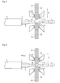
- the wires 1, 2, 3, 4 according to the FIG. 3 largely stretched and arranged according to a fork shape, so that the ends of the wires 1, 2, 3, 4 lie in a plane.
- the ends of the wires 1, 2, 3, 4 each have a longitudinal axis A1, A2, A3, A4, wherein the longitudinal axes A1, A2, A3, A4 are arranged substantially parallel to one another and correspondingly in a plane.
- the wires 1, 2, 3, 4 are first according to the FIG. 4 cut off along a line L1. Thereafter, the ends of the wires 1, 2, 3, 4 stripped away over a length xc away, so that the conductors 1.1, 2.1, 3.1, 4.1 are exposed there.
- the conductors 1.1, 2.1, 3.1, 4.1 comprise, as mentioned above, twisted individual wires, wherein in the figures for clarity, the explicit representation of the individual wires was omitted.
- a heating device 10 which is designed substantially hollow cylindrical, pushed over the first conductor 1.1.
- the heating device 10 is designed here as an induction heating device and comprises a coil through which a corresponding alternating current flows, so that a heat-generating eddy current is induced in the conductor 1.1.
- a sleeve 6 In immediate connection thereto, a sleeve 6 according to the FIGS. 6a, 6b connected in a crimping device with the first conductor 1.1.
- the electrically conductive sleeve 6 comprises in the illustrated embodiment, an open crimping claw 6.1 and a coupling end 6.2, which is suitable for producing a plug connection with another coupling part in the intended use of the cable.
- the heater 10 is removed.
- the first conductor 1.1 is then fed to the crimping device, wherein the stripped first conductor 1.1 comes to rest in the crimping claw 6.1.
- the crimping claw 6.1 and the stripped first conductor 1.1 are located between a first tool 11, for example a crimping die, and a second tool 12, such as an anvil or a second crimping die, the crimping device (FIG. FIG. 7 ).
- the first tool 11 is moved along a z-direction relative to the second tool 12 within a processing stroke.
- FIG. 9 is a central longitudinal section through the first tool 11, the second tool 12, the sleeve 6 and represented by the first conductor 1.1, wherein also here on the sectional view of the individual wires has been omitted for better clarity.
- the first tool 11 and the second tool 12 have an axial length x and surround the sleeve 6 with the conductor 1.1.
- the first tool 11 has a first crimping surface C11 and the second tool 12 has a second crimping surface C12.
- each comprises the first tool 11 and the second tool 12 a plurality of sub-elements 11.1 to 11.5; 12.1 to 12.5.
- the first crimping surface C11 extends over the sub-elements 11.1 to 11.5 of the first tool 11 and the second crimping surface C12 extends over the sub-elements 12.1 to 12.5 of the second tool 12.
- each of the sub-elements 11.1 to 11.5; 12.1 to 12.5 has a crimp surface C11, C12.
- the crimping surfaces C11, C12 are adapted to come into mechanical contact with the sleeve 6, in particular with the crimping claw 6.1 in order to plastically deform them.
- the sub-elements 11.1 to 11.5 of the first tool 11 are arranged in the z-direction relative to each other displaceable.
- the sub-elements 12.1 to 12.5 of the second tool 12 in the z-direction are arranged relative to each other displaceable. So it is the sub-elements 11.1 to 11.5; 12.1 to 12.5 one and the same tool 11, 12 arranged in the z-direction relative to each other displaceable.
- the crimped connection device is shown in a position at the beginning of the crimping process in which the tools 11, 12 are in a first relative position I and the crimping surfaces C11, C12 are opposite each other over an axial length x in the z-direction are arranged.
- the two points P11.1, P11.2, P11.3; P12.1, P12.2, P12.3 of a pair of points are arranged opposite each other in the z-direction in which FIG. 9 ie one above the other (pairs of points: P11.1 - P12.1 / P11.2 - P12.2 / P11.3 - P12.3).
- the distances z1, z2, z3 between the associated points P11.1, P11.2, P11.3; P12.1, P12.2, P12.3 have different sizes (relative position I: z1 ⁇ z2 ⁇ z3)
- the tools 11, 12 are shown in the first relative position I.
- the crimping claw 6.1 is already incompletely plastically deformed, so that upon further reduction of the spacing of the tools 11, 12, compression of the first conductor 1.1 begins.
- the action starts first a first axial section a of the conductor 1.1 produces a compression of the conductor 1.1 or the associated individual wires.
- the compression of the conductor 1.1 by the subelements 11.2, 11.4, 12.2, 12.4 is subsequently extended to the second axial subsection b, which is larger in comparison to the first axial subsection a. Accordingly, the remnants of the insulation 1.2 between the twisted individual wires of the conductor 1.1 are further urged axially outward, in particular in the third axial section c. Finally, upon further movement of the tools 11, 12, the subelements 11.1, 11.5, 12.1, 12.5 also compress the heated individual wires, so that the accumulated remnants of the insulation 1.2 between the twisted individual wires are also forced out of the third axial subsection c.
- the device for producing a cable has for this purpose two shafts 15, 16, which are designed in the manner of a camshaft.
- Each of the shafts 15, 16 rotates about its own axis, wherein by cams or by eccentric raceways these rotational movements in each case in a longitudinal movement of the relative to each other in the z-direction displaceable Subelements 11.1 to 11.5. and sub-elements 12.1 to 12.5 is converted.
- the sub-elements 11.1 to 11.5, 12.1 to 12.5 have assumed a relative position to each other, in which the crimping surfaces C11, 12 have no steps.
- the crimping device has guide rollers 14 which axially (in the direction of the longitudinal axis of the conductor to be crimped) the packages of the sub-elements 11.1 to 11.5, 12.1 to 12.5 ) together.
- the second conductor 1.2 is already heated by the heating device. Once the first crimping is completed, then the second crimping can be done immediately, while then already the third conductor 1.3 is heated. In this way, all conductors 1.1 to 4.1 can be sequentially processed (heated and crimped), Alternatively, of course, a parallel processing can be carried out with a correspondingly configured device, so that all conductors 1.1 to 4.1 are heated simultaneously and crimped immediately immediately thereafter.
- a heating device may be provided, so that the tools 11, 12 are heated during the crimping process.
- the sleeve 6 can be heated during the crimping process by a corresponding heater.
- the device comprises a first tool 11 ', which is designed in one piece, for example as a one-piece crimping die.
- the second tool 12 ' is equally made in one piece and serves as an anvil.
- the first tool 11 ' has a wave-like crimping surface C11'
- the second tool 12 ' has a substantially hollow-cylindrical crimping surface C12', so that in a first relative position I according to the FIG.
- a crimping process is carried out, in which the heated conductor 1.1, 2.1, 3.1, 4.1 is electrically contacted with the sleeve 6.
- the pressing is carried out in such a way that initially a compression of the conductor 1.1, 2.1, 3.1, 4.1 is generated at the first axial section a of the conductor 1.1, 2.1, 3.1, 4.1. Subsequently, the compression of the conductor 1.1, 2.1, 3.1, 4.1 is extended to a larger second axial portion b and finally to the even larger axial portion c.
- a heating device may be provided, so that the tools 11 ', 12' are heated during the crimping process.
- the sleeve 6 can be heated during the crimping process by a corresponding heater.
- FIGS. 11 and 12 a variant according to a third embodiment is shown.
- the third embodiment differs from the first and second embodiments substantially by a another embodiment of the crimping device. Thereafter, the device comprises a first tool 11 "and a second tool 12", which are each designed in one piece, for example as a one-piece crimping die.
- the tools 11 ", 12" each have an oblique or conical crimping surface C11 ", C12".
- a crimping process is performed in which the heated conductor 1.1, 2.1, 3.1, 4.1 is electrically contacted with the sleeve 6.
- the tools 11 ", 12" are moved not only in the z-direction to each other, but also during the crimping process about an axis which is oriented perpendicular to the z-direction and also perpendicular to the axis A1, in the direction of arrows B, -B panned.
- the pressing is now carried out here in such a way that initially a compression of the conductor 1.1, 2.1, 3.1, 4.1 is generated at the first axial section a of the conductor 1.1, 2.1, 3.1, 4.1. Subsequently, the compression of the conductor 1.1, 2.1, 3.1, 4.1 is widened as a result of the movement in the z direction and the superimposed pivotal movement on a larger second axial portion b and finally on the even larger axial portion c.
- a heating device may be provided, so that the tools 11 ", 12" are heated during the crimping process.
- the sleeve 6 can be heated during the crimping process by a corresponding heater.
- FIG. 12 is a relative position II of the tools 11 ", 12" shown at the end of the machining stroke, in which the tools 11 ", 12" moved together in the z-direction and in the direction of the arrows B, -B are pivoted.
Landscapes
- Engineering & Computer Science (AREA)
- Manufacturing & Machinery (AREA)
- Manufacturing Of Electrical Connectors (AREA)
- Connections Effected By Soldering, Adhesion, Or Permanent Deformation (AREA)
- Processes Specially Adapted For Manufacturing Cables (AREA)
Abstract
Description
- Die Erfindung betrifft ein Verfahren zur Herstellung eines konfektionierten Kabels gemäß dem Anspruch 1. Weiterhin umfasst die Erfindung eine Vorrichtung zum Herstellen bzw. Konfektionieren eines derartigen Kabels gemäß dem Anspruch 10 sowie ein mit dem Verfahren beziehungsweise mit der Vorrichtung hergestelltes Kabel nach Anspruch 15.
- Die betreffenden Kabel sind etwa in Kraftfahrzeugen oder Luftfahrzeugen einsetzbar und werden meist in großen Stückzahlen benötigt. Zur kostengünstigen Bereitstellung entsprechender Kabel sind ein einfacher Aufbau und eine einfache Konfektionierbarkeit von großer Bedeutung.
- Aus der
WO 03/097289 A1 - Der Erfindung liegt die Aufgabe zugrunde, ein Verfahren zur Herstellung von qualitativ hochwertigen Kabeln zu schaffen, welches erlaubt Kabel mit vergleichsweise geringem Herstellungsaufwand zu produzieren. Außerdem umfasst die Erfindung auch eine neuartige Vorrichtung zur Herstellung von derartigen qualitativ hochwertigen Kabeln und nach dem Verfahren hergestellte Kabel.
- Diese Aufgabe wird erfindungsgemäß durch die Merkmale der Ansprüche 1, 10 beziehungsweise des Anspruchs 15 gelöst.
- Erfindungsgemäß dient das Verfahren zur Herstellung eines Kabels, welches einen Leiter aufweist, der mehrere Einzeldrähte umfasst. Der Leiter ist zumindest abschnittsweise, insbesondere entlang eines axialen Abschnitts des Leiters, von einer Isolierung umgeben. Zudem weist der Leiter eine Hülse auf. Das Verfahren umfasst folgende Schritte:
- Aufheizen des Leiters,
- Durchführung eines Crimpprozesses zur elektrischen Kontaktierung der Hülse mit dem Leiter, wobei bei dem Crimpprozess die Hülse mit dem aufgeheizten Leiter in einer Weise verpresst wird, dass
zunächst eine Kompression des Leiters an einem ersten axialen Teilabschnitt des Leiters erzeugt wird und
darauffolgend die Kompression des Leiters auf einen größeren zweiten axialen Teilabschnitt des Leiters ausgeweitet wird. - In vorteilhafter Weise wird der Crimpprozess unmittelbar im Anschluss an das Aufheizen des Leiters durchgeführt.
- Das Aufheizen des Leiters wird so vorgenommen, dass dieser in sehr kurzer Zeit auf die gewünschte Temperatur aufgeheizt wird. Entsprechend wird das Aufheizen mit vergleichsweise hoher Leistung vorgenommen.
- Mit Vorteil wird das Aufheizen des Leiters durch einen Induktionsprozess vorgenommen.
- Vorzugsweise wird zur Durchführung des Crimpprozesses ein erstes Werkzeug entlang einer z-Richtung relativ zu einem zweiten Werkzeug bewegt und das erste Werkzeug und / oder das zweite Werkzeug werden beheizt. Insbesondere wird die Hülse mit dem Leiter unter Verwendung eines ersten Werkzeugs mit einer ersten Crimpfläche und eines zweiten Werkzeugs mit einer zweiten Crimpfläche verpresst. Zur Durchführung dieses Crimpprozesses wird das erste Werkzeug entlang einer z-Richtung relativ zum zweiten Werkzeug bewegt. Weiterhin werden das erste Werkzeug oder das zweite Werkzeug oder beide Werkzeuge aufgeheizt, wobei das Aufheizen beziehungsweise eine Temperierung des Leiters durch den Kontakt mit dem aufgeheizten Werkzeug erfolgt. Der zeitliche Ablauf des Crimpprozesses wird auch bei dieser Ausgestaltung des Verfahrens so eingestellt, dass der Leiter die erforderliche Verarbeitungstemperatur erreicht hat, bevor der Crimpprozess abgeschlossen ist.
- Die Crimpflächen sind diejenigen Flächen der Werkzeuge, die während des Crimpprozesses mit der Hülse beziehungsweise mit dem Leiter in Berührkontakt gebracht werden. Die Crimpflächen können zur Optimierung der Standzeit der Werkzeuge behandelt, insbesondere beschichtet sein, so dass der Reibungskoeffizient und der Haftreibungsverschleiß reduziert sind. Ebenso können durch eine geeignete Beschichtung der Crimpflächen der Werkzeuge Materialanlagerungen und Kaltverschweißen im Laufe der Betriebszeit reduziert beziehungsweise vermieden werden.
- In vorteilhafter Weise wird vor der Durchführung des Aufheizens die Isolierung zumindest abschnittsweise entfernt. Insbesondere wird die Isolierung an demjenigen axialen Abschnitt des Kabels entfernt, an dem darauffolgend die Hülse mit dem Leiter elektrisch kontaktiert wird.
- Mit Vorteil ist der Crimpprozess so ausgestaltet, dass die Ausweitung der Kompression des Leiters ausgehend vom ersten axialen Teilabschnitt axial zu beiden Seiten des ersten axialen Teilabschnitts erfolgt.
- Alternativ kann auch der Leiter vor der Durchführung des Crimpprozesses nicht abisoliert werden, so dass durch die hohe Temperatur des Leiters gegebenenfalls in Verbindung mit einem oder mehreren aufgeheizten Werkzeugen das weiche oder flüssige Material der Isolierung während des Crimpprozesses axial verdrängt wird.
- In weiterer Ausgestaltung der Erfindung umfasst das Material der Isolierung Ethylenvinylacetat (EVA) oder PEVA (Polyethylen-Vinylacetat).
- Vorzugsweise ist der Leiter so ausgestaltet, dass dessen Einzeldrähte eine Schlaglänge von mindestens 12 mm, insbesondere von mindestens 20 mm, insbesondere von mindestens 30 mm aufweisen. Der Begriff Schlaglänge beschreibt die Länge der Strecke, die ein einziger der Einzeldrähte des Leiters für eine 360° Drehung benötigt.
- Vorzugsweise weist der Leiter einer Ader mindestens 10 Einzeldrähte, insbesondere mindestens 20 Einzeldrähte, auf.
- Mit Vorteil wird der Crimpprozess bei einer Temperatur des Leiters von über 60 °C durchgeführt, vorzugsweise bei einer Temperatur von über 150 °C, insbesondere bei einer Temperatur von über 200 °C. Insbesondere ist es vorteilhaft, wenn der Crimpprozess bei einer Temperatur des Leiters durchgeführt wird, die über der Schmelztemperatur des Materials der Isolierung liegt.
- In weiterer Ausgestaltung der Erfindung weist das Kabel mehrere Leiter auf, die jeweils mehrere Einzeldrähte umfassen. Die Leiter sind zumindest abschnittsweise jeweils von einer Isolierung umgeben. Das Kabel weist zudem mehrere Hülsen auf, wobei bei einem aufgeheizten Leiter der Crimpprozess zur elektrischen Kontaktierung der Hülse durchgeführt wird, während gleichzeitig ein anderer Leiter aufgeheizt wird, zur Vorbereitung des Crimpprozesses für den anderen Leiter.
- Die Erfindung betrifft auch eine Vorrichtung zum Herstellen eines Kabels, das einen Leiter insbesondere mit mehreren Einzeldrähten aufweist, wobei der Leiter mit einer Hülse durch eine Crimpverbindung elektrisch kontaktiert ist. Die Vorrichtung umfasst eine Heizvorrichtung zum Aufheizen des Leiters. Weiterhin weist die Vorrichtung ein erstes Werkzeug mit einer ersten Crimpfläche und ein zweites Werkzeug mit einer zweiten Crimpfläche auf. Zur Herstellung der Crimpverbindung ist das erste Werkzeug entlang einer z-Richtung über einen Bearbeitungshub hinweg relativ zum zweiten Werkzeug bewegbar. In einer ersten Relativposition der Werkzeuge zueinander sind die Crimpflächen über eine axiale Länge hinweg in z-Richtung einander gegenüberliegend angeordnet. Zudem liegen in der ersten Relativposition, die insbesondere am Beginn des Verpressens der Hülse von den Werkzeugen eingenommen wird, Punktepaare vor, die jeweils einen ersten Punkt auf der ersten Crimpfläche und einen zweiten Punkt auf der zweiten Crimpfläche umfassen. Die beiden Punkte eines Punktepaares sind in z-Richtung einander gegenüberliegend angeordnet, wobei für axial zueinander beabstandete Punktepaare die Abstände in z-Richtung zwischen den zugehörigen Punkten eines Punktepaars unterschiedlich groß sind.
- Der Begriff "axial" bedeutet in Richtung der Längsachse des zu crimpenden Leiters, also orthogonal zur z-Richtung.
- Der Leiter ist üblicherweise zumindest abschnittsweise also in einem axialen Abschnitt von einer Isolierung umgeben.
- Mit Vorteil ist die Heizvorrichtung als Induktionsheizvorrichtung ausgestaltet, insbesondere weist die Heizvorrichtung eine elektromagnetische Spule auf.
- In weiterer Ausgestaltung der Erfindung ist das erste Werkzeug oder das zweite Werkzeug beheizbar. Alternativ können auch beide Werkzeuge beheizbar sein. In diesem Fall kann die Heizvorrichtung als elektrische Widerstandsheizung zum Aufheizen des ersten und / oder des zweiten Werkzeugs ausgestaltet sein.
- Vorzugsweise umfasst das erste Werkzeug und / oder das zweite Werkzeug mehrere Teilelemente, wobei jedes der Teilelemente eine Crimpfläche aufweist. Die Teilelemente des ersten Werkzeugs sind in z-Richtung relativ zueinander verschiebbar angeordnet. Alternativ oder zusätzlich können auch die Teilelemente des zweiten Werkzeugs in z-Richtung relativ zueinander verschiebbar angeordnet sein.
- Insbesondere kann die Vorrichtung so ausgestaltet sein, dass zur Herstellung der Crimpverbindung das erste Werkzeug entlang der z-Richtung relativ zum zweiten Werkzeug innerhalb eines Bearbeitungshubs bewegbar ist, wobei mit zunehmender Annäherung der Werkzeuge zueinander die Unterschiede der Abstände zwischen Punkten, die zu unterschiedlichen axial beabstandeten Punktepaaren gehörigen, kleiner werden. Somit eilt also zumindest ein Teilelement eines Werkzeugs zumindest einem anderen Teilelement desselben Werkzeugs bei der Bewegung in z-Richtung zeitlich voraus.
- Die Erfindung betrifft auch ein nach dem erfindungsgemäßen Verfahren hergestelltes Kabel, das einen Leiter mit mehreren Einzeldrähten aufweist, welcher zumindest abschnittsweise von einer Isolierung umgeben ist, wobei das Kabel zudem eine Hülse aufweist, die mit dem Leiter durch eine Crimpverbindung elektrisch kontaktiert ist.
- Durch die Erfindung ist es möglich qualitativ hochwertige Kabel herzustellen. Insbesondere werden Reste der Isolierung aus dem axialen Teilabschnitt des Kabels der elektrisch mit der Hülse kontaktiert ist, verdrängt beziehungsweise gequetscht. In der Folge entsteht ein Kabel, das eine weitgehend rückstandsfreie Crimpverbindung aufweist. Die Erfindung ist insbesondere für Kabel mit vergleichsweise großer Schlaglänge und mit einer Vielzahl von Einzeldrähten vorteilhaft.
- Vorteilhafte Ausbildungen der Erfindung entnimmt man den abhängigen Ansprüchen.
- Weitere Einzelheiten und Vorteile des erfindungsgemäßen Kabels ergeben sich aus der nachfolgenden Beschreibung von Ausführungsbeispielen anhand der beiliegenden Figuren.
- Es zeigen die
- Figur 1a
- eine Seitenansicht eines Kabels mit einem Schneidwerkzeug zu Beginn der Verarbeitung,
- Figur 1b
- eine Vorderansicht des Kabels,
- Figur 2
- eine Seitenansicht des Kabels an dessen Ende Adern des Kabels freigelegt ist,
- Figur 3
- eine Seitenansicht des Kabels nach einem weiteren Verarbeitungsschritt,
- Figur 4
- eine Seitenansicht des Kabels, nach einem Schneidprozess und einem Absisolierschritt,
- Figur 5
- eine Seitenansicht des Kabels mit einer Heizvorrichtung,
- Figur 6a
- eine Seitenansicht einer Hülse,
- Figur 6b
- eine Frontansicht der Hülse,
- Figur 7
- eine Seitenansicht des Kabels mit Werkzeugen zum Crimpen in einer ersten Relativposition,
- Figur 8
- eine Seitenansicht des Kabels mit Werkzeugen zum Crimpen,
- Figur 9
- eine Detailansicht im Längsschnitt der Werkzeuge mit dem Kabel in der ersten Relativposition,
- Figur 10
- eine Detailansicht im Längsschnitt der Werkzeuge mit dem Kabel in der ersten Relativposition gemäß einen zweiten Ausführungsbeispiel,
- Figur 11
- eine Detailansicht im Längsschnitt der Werkzeuge mit dem Kabel in der ersten Relativposition gemäß einen dritten Ausführungsbeispiel,
- Figur 12
- eine Detailansicht im Längsschnitt der Werkzeuge mit dem Kabel in der zweiten Relativposition gemäß einen dritten Ausführungsbeispiel.
- In der
Figur 1a ist eine Seitenansicht eines Endes eines Kabels gezeigt, welches bearbeitet beziehungsweise konfektioniert werden soll. In dieser Abbildung ist vom Kabel nur ein äußerer Mantel 5 erkennbar, wobei der Mantel 5 aus elektrisch isolierendem Material, beispielsweise aus einem thermoplastischen Elastomer, insbesondere auf Urethanbasis, hergestellt ist. - Das Kabel weist im vorgestellten Ausführungsbeispiel vier verdrillte Adern 1, 2, 3, 4 auf. Die Adern 1, 2, 3, 4 umfassen jeweils einen innen liegenden Leiter 1.1, 2.1, 3.1, 4.1 (
Figur 1 b) , wobei jeder der Leiter 1.1, 2.1, 3.1, 4.1 aus einer Vielzahl von verseilten Einzeldrähten besteht. Im vorgestellten Ausführungsbeispiel beträgt die Schlaglänge 20 mm. Jede der Adern 1, 2, 3, 4 beziehungsweise jeder Leiter 1.1,2.1,3.1, 4.1 weist hier 27 Einzeldrähte auf. - Jeder Leiter 1.1, 2.1, 3.1, 4.1 ist jeweils von einer Isolierung 1.2, 2.2, 3.2, 4.2 umgeben. Das Material für die Isolierungen 1.2, 2.2, 3.2, 4.2 ist im vorgestellten Ausführungsbeispiel Ethylenvinylacetat (EVA). Radial außerhalb bezüglich der Adern 1, 2, 3, 4 befindet sich der Mantel 5.
- Im Zuge der Konfektionierung wird das Ende des Kabels zunächst in einer Vorrichtung zum Herstellen des konfektionierten Kabels mit einem Schneidwerkzeug 13 bearbeitet (
Figur 1a ). Das Schneidwerkzeug umfasst zwei Schneidklingen 13.1, 13.2, die eine V-förmige Form zum Umgriff des Mantels 5 aufweisen. Um den Mantel 5, zu scheiden werden die Schneidklingen 13.1, 13.2 orthogonal zur Längsachse des Kabels einander angenähert, bis die Schneidklingen 13.1, 13.2 mit genügender Tiefe in den Mantel 5 eingedrungen sind. Danach wird das Ende des Mantels 5 in axialer Richtung abgezogen, so dass schließlich gemäß derFigur 2 der Mantel 5 an einem Ende des Kabels entfernt ist und dort die innen liegenden Adern 1, 2, 3, 4 freigelegt sind. - In einem darauffolgenden Schritt der Herstellung beziehungsweise Konfektionierung des Kabels werden die Adern 1, 2, 3, 4 gemäß der
Figur 3 weitgehend gestreckt und entsprechend einer Gabelform angeordnet, so dass die Enden der Adern 1, 2, 3, 4 in einer Ebene liegen. Die Enden der Adern 1, 2, 3, 4 weisen jeweils eine Längsachse A1, A2, A3, A4 auf, wobei die Längsachsen A1, A2, A3, A4 im Wesentlichen parallel zueinander und entsprechend in einer Ebene angeordnet sind. - Zur Erreichung einer definierten Länge der Adern 1, 2, 3, 4 werden diese zunächst gemäß der
Figur 4 entlang einer Linie L1 abgeschnitten. Danach werden die Enden der Adern 1, 2, 3, 4 über eine Länge xc hinweg abisoliert, so dass die Leiter 1.1, 2.1, 3.1, 4.1 dort freigelegt sind. Die Leiter 1.1, 2.1, 3.1, 4.1 umfassen, wie oben erwähnt, verdrillte Einzeldrähte, wobei in den Figuren der Übersichtlichkeit halber auf die explizite Darstellung der Einzeldrähte verzichtet wurde. Herstellungsbedingt befinden sich auch in den abisolierten Bereichen der Leiter 1.1, 2.1, 3.1, 4.1 Reste der Isolierungen 1.2, 2.2, 3.2, 4.2 zwischen den verdrillten Einzeldrähten der Leiter 1.1, 2.1, 3.1,4.1. - Im nächsten Bearbeitungsschritt wird eine Heizvorrichtung 10, die im Wesentlichen hohlzylindrisch ausgestaltet ist, über den ersten Leiter 1.1 geschoben. Die Heizvorrichtung 10 ist hier als eine Induktionsheizvorrichtung ausgestaltet und umfasst eine Wendel, durch die ein entsprechender Wechselstrom fließt, so dass im Leiter 1.1 ein Wärme erzeugender Wirbelstrom induziert wird.
- In unmittelbaren Anschluss daran wird eine Hülse 6 gemäß den
Figuren 6a, 6b in einer Crimpvorrichtung mit dem ersten Leiter 1.1 verbunden. Die elektrisch leitende Hülse 6 umfasst im vorgestellten Ausführungsbeispiel eine offene Crimpkralle 6.1 sowie ein Kupplungsende 6.2, das zur Herstellung einer Steckverbindung mit einem weiteren Kupplungsteil im bestimmungsgemäßen Einsatz des Kabels geeignet ist. - Nachdem der erste Leiter 1.1 soweit aufgeheizt wurde, dass dieser im abisolierten Bereich eine Temperatur aufweist, die über der Schmelztemperatur der Isolierung 1.2 liegt, wird die Heizung 10 entfernt. Der erste Leiter 1.1 wird sodann der Crimpvorrichtung zugeführt, wobei der abisolierte erste Leiter 1.1 in der Crimpkralle 6.1 zu liegen kommt. Die Crimpkralle 6.1 und der abisolierte erste Leiter 1.1 befinden sich zwischen einem ersten Werkzeug 11, zum Beispiels einem Crimpstempel, und einem zweiten Werkzeug 12, etwa einem Amboss oder einem zweiten Crimpstempel, der Crimpvorrichtung (
Figur 7 ). - Zum Crimpen des ersten Leiters 1.1 wird das erste Werkzeug 11 entlang einer z-Richtung relativ zum zweiten Werkzeug 12 innerhalb eines Bearbeitungshubs bewegt.
- In der
Figur 9 ist ein mittiger Längsschnitt durch das erste Werkzeug 11, das zweite Werkzeug 12, die Hülse 6 sowie durch den ersten Leiter 1.1 dargestellt, wobei auch hier auf die Schnittdarstellung der Einzeldrähte der besseren Übersichtlichkeit halber verzichtet wurde. Das erste Werkzeug 11 und das zweite Werkzeug 12 weisen eine axiale Länge x auf und umgreifen die Hülse 6 mit dem Leiter 1.1. Zudem weisen das erste Werkzeug 11 eine erste Crimpfläche C11 und das zweite Werkzeug 12 eine zweite Crimpfläche C12 auf. - Gemäß dem ersten Ausführungsbeispiel nach
Figur 9 umfasst jeweils das erste Werkzeug 11 und das zweite Werkzeug 12 mehrere Teilelemente 11.1 bis 11.5; 12.1 bis 12.5. Die erste Crimpfläche C11 erstreckt sich über die Teilelemente 11.1 bis 11.5 des ersten Werkzeugs 11 und die zweite Crimpfläche C12 erstreckt sich über die Teilelemente 12.1 bis 12.5 des zweiten Werkzeugs 12. Somit weist jedes der Teilelemente 11.1 bis 11.5; 12.1 bis 12.5 eine Crimpfläche C11, C12 auf. - Die Crimpflächen C11, C12 sind dazu eingerichtet mit der Hülse 6, insbesondere mit der Crimpkralle 6.1 in mechanischen Kontakt zu kommen um diese plastisch zu verformen.
- Die Teilelemente 11.1 bis 11.5 des ersten Werkzeugs 11 sind in z-Richtung relativ zueinander verschiebbar angeordnet. Ebenso sind die Teilelemente 12.1 bis 12.5 des zweiten Werkzeugs 12 in z-Richtung relativ zueinander verschiebbar angeordnet. Es sind also die Teilelemente 11.1 bis 11.5; 12.1 bis 12.5 ein und desselben Werkzeugs 11, 12 in z-Richtung relativ zueinander verschiebbar angeordnet.
- In der
Figur 9 ist die Vorrichtung zur Herstellung der Crimpverbindung in einer Stellung am Beginn des Crimpprozesse gezeigt, in der die Werkzeuge 11, 12 in einer ersten Relativposition I zueinander stehen und in der die Crimpflächen C11, C12 über eine axiale Länge x hinweg in z-Richtung einander gegenüberliegend angeordnet sind. - Geometrisch betrachtet liegen bei der Vorrichtung zur Herstellung der Crimpverbindung Punktepaare vor, die jeweils einen ersten Punkt P11.1, P11.2, P11.3 auf der ersten Crimpfläche C11 und einen zweiten Punkt P12.1, P12.2, P12.3 auf der zweiten Crimpfläche C12 umfassen.
- Die beiden Punkte P11.1, P11.2, P11.3; P12.1, P12.2, P12.3 eines Punktepaares sind in z-Richtung gegenüberliegend angeordnet, in der
Figur 9 also übereinander dargestellt (Punktepaare: P11.1 - P12.1 / P11.2 - P12.2 / P11.3 - P12.3). Dabei gilt, dass in der ersten Relativposition I für axial zueinander beabstandete Punktepaare die Abstände z1, z2, z3 zwischen den zugehörigen Punkten P11.1, P11.2, P11.3; P12.1, P12.2, P12.3 unterschiedlich groß sind (Relativposition I: z1 ≠ z2 ≠ z3) - In der
Figur 9 sind die Werkzeuge 11, 12 in der ersten Relativposition I gezeigt. In dieser Relativposition I ist die Crimpkralle 6.1 bereits unvollständig plastisch verformt, so dass bei weiterer Verkleinerung des Abstandes der Werkzeuge 11, 12 eine Kompression des ersten Leiters 1.1 beginnt. In der ersten Relativposition I ist der Abstand z1, z2, z3 von den einander in z-Richtung gegenüberliegender Crimpflächen beziehungsweise Punktepaaren P11.1 - P12.1 / P11.2 - P12.2 / P11.3 - P12.3 des ersten und des zweiten Werkzeugs 11, 12 über die axiale Länge x hinweg unterschiedlich groß. In denFiguren 7, 8 und9 ist der Unterschied zwischen den Abständen z1, z2, z3 zur Verdeutlichung überpropotional groß dargestellt. In der Realität können die Differenzen Δz21 = z2-z1 beziehungsweise Δz32 = z3-z2 weniger als ein Millimeter betragen. - Wenn nun ausgehend von der Relativposition I die Werkzeuge 11, 12 entlang der z-Richtung weiter zusammengefahren werden, wird zunächst an einem ersten axialen Teilabschnitt a des Leiters 1.1 eine Kompression des Leiters 1.1 beziehungsweise der zugehörigen Einzeldrähte erzeugt.
- Die Reste der Isolierungen 1.2, 2.2, 3.2, 4.2 zwischen den verdrillten Einzeldrähten der Leiter 1.1, 2.1, 3.1, 4.1 sind aufgrund der durch die Aufheizung vorherrschenden Temperaturen im Leiter 1.1 so heiß, dass diese weich beziehungsweise flüssig sind. In der Folge werden diese Reste im Zuge des Crimpprozesses in axialer Richtung bezüglich der mittleren Teilelemente 11.3, 12.3 beidseitig in Richtung der Achse A1 nach außen gedrängt, also außerhalb des ersten axialen Teilabschnitts a in einen zweiten axialen Teilabschnitt b. Bei fortschreitender Reduzierung des Abstandes der Werkzeuge 11, 12 wird darauffolgend die Kompression des Leiters 1.1 durch die Teilelemente 11.2, 11.4, 12.2, 12.4 auf den im Vergleich zum ersten axialen Teilabschnitt a größeren zweiten axialen Teilabschnitt b ausgeweitet. Demgemäß werden die Reste der Isolierung 1.2 zwischen den verdrillten Einzeldrähten des Leiters 1.1 weiter axial nach außen gedrängt, insbesondere in den dritten axialen Teilabschnitt c. Schließlich komprimieren bei weiterem Zusammenfahren der Werkzeuge 11, 12 auch die Teilelemente 11.1, 11.5, 12.1, 12.5 die aufgeheizten Einzeldrähte, so dass die akkumulierten Reste der Isolierung 1.2 zwischen den verdrillten Einzeldrähten auch aus dem dritten axialen Teilabschnitt c gedrängt werden.
- Die Crimpvorrichtung ist so ausgestaltet, dass ab einem bestimmten Mindestabstand zwischen den mittleren Teilelementen 11.3, 12.3 bei weiterem Zusammenfahren der Werkzeuge 11, 12 die Differenzen Δz21 = z2-z1 beziehungsweise Δz32 = z3-z2 kleiner werden und in der Endstellung der Werkzeuge 11, 12, wenn also die Verformung der Hülse 6 abgeschlossen ist, die Differenzen Δz21 und Δz32 den Wert Null annehmen (Relativposition II gemäß der
Figur 8 ). - Die Vorrichtung zum Herstellen eines Kabels weist zu diesem Zweck zwei Wellen 15, 16 auf, die nach Art einer Nockenwelle ausgebildet sind. Jede der Wellen 15, 16 dreht sich um die eigene Achse, wobei durch Nocken beziehungsweise durch exzentrische Laufbahnen diese Drehbewegungen jeweils in eine Längsbewegung der relativ zueinander in z-Richtung verschiebbaren Teilelemente 11.1 bis 11.5. und Teilelemente 12.1 bis 12.5 umgewandelt wird. Am Ende des Bearbeitungshubs gemäß der
Figur 8 , also in der zweiten Relativposition II haben die Teilelemente 11.1 bis 11.5, 12.1 bis 12.5 eine relative Lage zueinander eingenommen, bei der die Crimpflächen C11, 12 keine Stufen aufweisen. Damit die vergleichsweise dünnen Teilelemente 11.1 bis 11.5, 12.1 bis 12.5 beim Crimpprozess nicht verformt oder auseinander gedrückt werden, weist die Crimpvorrichtung Führungsrollen 14 auf, welche die Pakete der Teilelemente 11.1 bis 11.5, 12.1 bis 12.5 axial (in Richtung der Längsachse des zu crimpenden Leiters) zusammenhalten. - Während der erste Leiter 1.1 und die Hülse 6 gecrimpt werden, wird bereits durch die Aufheizvorrichtung der zweite Leiter 1.2 aufgeheizt. Sobald die erste Crimpung abgeschlossen ist, kann dann umgehend die zweite Crimpung vorgenommen werden, während dann schon der dritte Leiter 1.3 aufgeheizt wird. Auf diese Weise können sequentiell alle Leiter 1.1 bis 4.1 bearbeitet (aufgeheizt und gecrimpt) werden, Alternativ kann natürlichen auch eine parallele Verarbeitung mit einer entsprechend ausgestalteten Vorrichtung vorgenommen werden, so dass alle Leiter 1.1 bis 4.1 gleichzeitig aufgeheizt und unmittelbar darauffolgend gleichzeitig gecrimpt werden.
- Für eines der Werkzeuge 11, 12 oder für beide kann eine Heizvorrichtung vorgesehen sein, so dass die Werkzeuge 11, 12 beim Crimpprozess aufgeheizt sind. Gleichermaßen kann die Hülse 6 beim Crimpprozess durch eine entsprechende Heizvorrichtung aufgeheizt werden.
- In der
Figur 10 ist ein zweites Ausführungsbeispiel gezeigt, das sich vom ersten Ausführungsbeispiel im Wesentlichen durch eine andere Ausgestaltung der Crimpvorrichtung unterscheidet. Demnach umfasst die Vorrichtung ein erstes Werkzeug 11', welches einstückig ausgestaltet ist, beispielsweise als ein einstückiger Crimpstempel. Das zweite Werkzeug 12' ist gleichermaßen einstückig ausgeführt und dient hier als Amboss. Das erste Werkzeug 11' weist eine wellenartige Crimpfläche C11' auf, während das zweite Werkzeug 12' eine im Wesentlichen hohlzylindrische Crimpfläche C12' aufweist, so dass in einer ersten Relativposition I gemäß derFigur 10 die Abstände z1, z2, z3 von einander in z-Richtung gegenüberliegender Punkte P11.1', P11.2', P11.3'; P12.1', P12.2', P12.3' auf den Crimpflächen C11', C12' des ersten und des zweiten Werkzeugs 11', 12' über die axiale Länge x hinweg unterschiedlich groß sind. Demgemäß liegen auch hier Punktepaare vor, die jeweils einen ersten Punkt P11.1', P11.2', P11.3' auf der ersten Crimpfläche C11' und einen zweiten Punkt P12.1', P12.2', P12.3' auf der zweiten Crimpfläche C12' umfassen, wobei die beiden Punkte P11.1', P11.2', P11.3'; P12.1', P12.2', P12.3' eines Punktepaares in z-Richtung gegenüberliegend angeordnet sind. Für axial zueinander beabstandete Punktepaare gilt, dass die Abstände z1, z2, z3 zwischen den zugehörigen Punkten P11.1', P11.2', P11.3'; P12.1', P12.2', P12.3' unterschiedlich groß sind. - Gemäß dem zweiten Ausführungsbeispiel wird nach dem Aufheizen eines der Leiter 1.1, 2.1, 3.1, 4.1 ein Crimprozess durchgeführt, bei dem der aufgeheizte Leiter 1.1, 2.1, 3.1, 4.1 mit der Hülse 6 elektrisch kontaktiert wird. Das Verpressen erfolgt in der Weise, dass zunächst eine Kompression des Leiters 1.1, 2.1, 3.1, 4.1 an dem ersten axialen Teilabschnitt a des Leiters 1.1, 2.1, 3.1, 4.1 erzeugt wird. Darauffolgend wird die Kompression des Leiters 1.1, 2.1, 3.1, 4.1 auf einen größeren zweiten axialen Teilabschnitt b ausgeweitet und schließlich auf den noch größeren axialen Teilabschnitt c. Somit wird erreicht, dass Reste der Isolierung 1.2, 2.2, 3.2, 4.2 im Zuge des Crimpprozesses in axialer Richtung beidseitig in Richtung der Achse A1 nach außen gedrängt werden, also außerhalb des axialen Teilabschnitts c.
- Für eines der Werkzeuge 11', 12' oder für beide kann eine Heizvorrichtung vorgesehen sein, so dass die Werkzeuge 11', 12' beim Crimpprozess aufgeheizt sind. Gleichermaßen kann die Hülse 6 beim Crimpprozess durch eine entsprechende Heizvorrichtung aufgeheizt werden.
- In den
Figuren 11 und 12 ist eine Variante gemäß einem dritten Ausführungsbeispiel gezeigt. Das dritte Ausführungsbeispiel unterscheidet sich vom ersten und zweiten Ausführungsbeispiel im Wesentlichen durch eine andere Ausgestaltung der Crimpvorrichtung. Danach umfasst die Vorrichtung ein erstes Werkzeug 11" und ein zweites Werkzeug 12", welche jeweils einstückig ausgestaltet sind, beispielsweise als einstückige Crimpstempel. Die Werkzeuge 11 ", 12" weisen jeweils eine schräge beziehungsweise konische Crimpfläche C11", C12" auf. In der Folge sind in einer ersten Relativposition I gemäß derFigur 11 die Abstände z1, z2, z3 von einander in z-Richtung gegenüberliegender Punkte P11.1", P11.2", P11.3"; P12.1", P12.2", P12.3" auf den Crimpflächen C11 ", C12" des ersten und des zweiten Werkzeugs 11", 12" über die axiale Länge x hinweg unterschiedlich groß. Demnach liegen auch hier Punktepaare vor, die jeweils einen ersten Punkt P11.1", P11.2", P11.3" auf der ersten Crimpfläche C11" und einen zweiten Punkt P12.1", P12.2", P12.3" auf der zweiten Crimpfläche C12' umfassen, wobei die beiden Punkte P11.1 ", P11.2", P11.3"; P12.1", P12.2", P12.3" eines Punktepaares in z-Richtung gegenüberliegend angeordnet sind. Für axial zueinander beabstandete Punktepaare gilt, dass die Abstände z1, z2, z3 zwischen den zugehörigen Punkten P11.1", P11.2", P11.3"; P12.1", P12.2", P12.3" unterschiedlich groß sind. - Auch gemäß dem dritten Ausführungsbeispiel wird nach dem Aufheizen eines der Leiter 1.1, 2.1, 3.1, 4.1 ein Crimprozess durchgeführt, bei dem der aufgeheizte Leiter 1.1, 2.1, 3.1, 4.1 mit der Hülse 6 elektrisch kontaktiert wird.
- Im dritten Ausführungsbeispiel werden die Werkzeuge 11", 12" nicht nur in z-Richtung zueinander bewegt, sondern auch während des Crimprozesses um eine Achse, die senkrecht zur z-Richtung und auch senkrecht zur Achse A1 orientiert ist, in Richtung der Pfeile B, -B geschwenkt.
- Das Verpressen erfolgt nun hier in der Weise, dass zunächst eine Kompression des Leiters 1.1, 2.1, 3.1, 4.1 an dem ersten axialen Teilabschnitt a des Leiters 1.1, 2.1, 3.1, 4.1 erzeugt wird. Darauffolgend wird die Kompression des Leiters 1.1, 2.1, 3.1, 4.1 in Folge der Bewegung in z-Richtung und der überlagerten Schwenkbewegung auf einen größeren zweiten axialen Teilabschnitt b ausgeweitet und schließlich auf den noch größeren axialen Teilabschnitt c. Somit wird auch hier erreicht, dass Reste der Isolierung 1.2, 2.2, 3.2, 4.2 im Zuge des Crimpprozesses in axialer Richtung, also in Richtung der Achse A1, nach außen gedrängt werden, außerhalb des axialen Teilabschnitts c.
- Für eines der Werkzeuge 11", 12" oder für beide kann eine Heizvorrichtung vorgesehen sein, so dass die Werkzeuge 11 ", 12" beim Crimpprozess aufgeheizt sind. Gleichermaßen kann die Hülse 6 beim Crimpprozess durch eine entsprechende Heizvorrichtung aufgeheizt werden.
- In der
Figur 12 ist eine Relativposition II der Werkzeuge 11", 12" am Ende des Bearbeitungshubs gezeigt, in der die Werkzeuge 11", 12" in z-Richtung zusammengefahren und in Richtung der Pfeile B, -B geschwenkt sind.
Claims (15)
- Verfahren zur Herstellung eines Kabels, das~ einen Leiter (1.1, 2.1, 3.1, 4.1) mit Einzeldrähten aufweist, welcher zumindest abschnittsweise von einer Isolierung (1.2, 2.2, 3.2, 4.2) umgeben ist und~ eine Hülse (6) aufweist,
mit folgenden Schritten:- Aufheizen des Leiters (1.1, 2.1, 3.1, 4.1),- Durchführung eines Crimpprozesses zur elektrischen Kontaktierung der Hülse (6) mit dem Leiter (1.1, 2.1, 3.1, 4.1), wobei bei dem Crimpprozess die Hülse (6) mit dem aufgeheizten Leiter (1.1, 2.1, 3.1, 4.1) in einer Weise verpresst wird, dass zunächst eine Kompression des Leiters (1.1, 2.1, 3.1, 4.1) an einem ersten axialen Teilabschnitt (a) des Leiters (1.1, 2.1, 3.1, 4.1) erzeugt wird und
darauffolgend die Kompression des Leiters (1.1, 2.1, 3.1, 4.1) auf einen größeren zweiten axialen Teilabschnitt (b, c) ausgeweitet wird. - Verfahren gemäß dem Anspruch 1, wobei das Aufheizen des Leiters (1.1, 2.1, 3.1, 4.1) durch einen Induktionsprozess vorgenommen wird.
- Verfahren gemäß einem der vorhergehenden Ansprüche, wobei zur Durchführung des Crimpprozesses ein erstes Werkzeug (11; 11'; 11") entlang einer z-Richtung relativ zu einem zweiten Werkzeug (12; 12'; 12") bewegt wird und das erste Werkzeug (11; 11'; 11") und / oder das zweite Werkzeug (12; 12'; 12") beheizt werden.
- Verfahren gemäß einem der vorhergehenden Ansprüche, wobei vor der Durchführung des Aufheizens die Isolierung (1.2, 2.2, 3.2, 4.2) zumindest abschnittsweise entfernt wird.
- Verfahren gemäß einem der vorhergehenden Ansprüche, wobei die Ausweitung der Kompression des Leiters (1.1, 2.1, 3.1, 4.1) ausgehend vom ersten axialen Teilabschnitt (a) zu beiden Seiten des ersten axialen Teilabschnitts (a) erfolgt.
- Verfahren gemäß einem der vorhergehenden Ansprüche, wobei das Material der Isolierung (1.2, 2.2, 3.2, 4.2) Ethylenvinylacetat umfasst.
- Verfahren gemäß einem der vorhergehenden Ansprüche, wobei der Leiter (1.1, 2.1, 3.1, 4.1) so ausgestaltet ist, dass dessen Einzeldrähte eine Schlaglänge von mindestens 12 mm aufweisen.
- Verfahren gemäß einem der vorhergehenden Ansprüche, wobei der Crimpprozess bei einer Temperatur des Leiters (1.1, 2.1, 3.1, 4.1) von über 60 °C durchgeführt wird.
- Verfahren gemäß einem der vorhergehenden Ansprüche, wobei das Kabel mehrere Leiter (1.1, 2.1, 3.1, 4.1) jeweils bestehend aus Einzeldrähten aufweist, welche zumindest abschnittsweise jeweils von einer Isolierung (1.2, 2.2, 3.2, 4.2) umgeben sind und das Kabel zudem mehrere Hülsen (6) aufweist, wobei bei einem aufgeheizten Leiter (1.1, 2.1, 3.1, 4.1) der Crimpprozess zur elektrischen Kontaktierung der Hülse (6) durchgeführt wird, während gleichzeitig ein anderer Leiter (1.1, 2.1, 3.1, 4.1) aufgeheizt wird.
- Vorrichtung zur Herstellung eines Kabels, das einen Leiter (1.1, 2.1, 3.1, 4.1) mit mehreren Einzeldrähten aufweist, welcher mit einer Hülse (6) durch eine Crimpverbindung elektrisch kontaktiert ist, wobei die Vorrichtung- eine Heizvorrichtung (10) zum Aufheizen des Leiters (1.1, 2.1, 3.1, 4.1),- ein erstes Werkzeug (11; 11'; 11") mit einer ersten Crimpfläche (C11, C11' C11") und- ein zweites Werkzeug (12; 12'; 12") mit einer zweiten Crimpfläche (C12, C12', C12") aufweist, wobei
zur Herstellung der Crimpverbindung das erste Werkzeug (11; 11'; 11") entlang einer z-Richtung relativ zum zweiten Werkzeug (12; 12'; 12") bewegbar ist und in einer ersten Relativposition (I) der Werkzeuge (11; 11'; 11"; 12; 12'; 12")
die Crimpflächen (C11, C11' C11"; C12, C12', C12") über eine axiale Länge (x) hinweg in z-Richtung einander gegenüberliegend angeordnet sind, und
Punktepaare vorliegen, die jeweils einen ersten Punkt (P11.1, P11.2, P11.3; P11.1', P11.2', P11.3'; P11.1", P11.2", P11.3") auf der ersten Crimpfläche (C11, C11' C11") und einen zweiten Punkt (P12.1, P12.2, P12.3; P12.1', P12.2', P12.3'; P12.1", P12.2", P12.3") auf der zweiten Crimpfläche (C12, C12', C12") umfassen, wobei die beiden Punkte (P11.1, P11.2, P11.3; P11.1', P11.2', P11.3'; P11.1", P11.2", P11.3"; P12.1, P12.2, P12.3; P12.1', P12.2', P12.3'; P12.1", P12.2", P12.3") eines Punktepaares in z-Richtung gegenüberliegend angeordnet sind, wobei für axial zueinander beabstandete Punktepaare die Abstände (z1, z2, z3) zwischen den zugehörigen Punkten (P11.1, P11.2, P11.3; P11.1', P11.2', P11.3'; P11.1", P11.2", P11.3"; P12.1, P12.2, P12.3; P12.1', P12.2', P12.3'; P12.1", P12.2", P12.3") unterschiedlich groß sind. - Vorrichtung gemäß dem Anspruch 10, wobei die Heizvorrichtung (10) als Induktionsheizvorrichtung ausgestaltet ist.
- Vorrichtung gemäß einem der Ansprüche 10 oder 11, wobei das erste Werkzeug (11; 11'; 11") und / oder das zweite Werkzeug (12; 12'; 12") beheizbar sind.
- Vorrichtung gemäß einem der Ansprüche 10 bis 12, wobei das erste Werkzeug (11) und / oder das zweite Werkzeug (12) mehrere Teilelemente (11.1 bis 11.5; 12.1 bis 12.5) umfasst, wobei jedes der Teilelemente (11.1 bis 11.5; 12.1 bis 12.5) eine Crimpfläche (C11, C12) aufweist und die Teilelemente (11.1 bis 11.5; 12.1 bis 12.5) des ersten Werkzeugs (11) und / oder des zweiten Werkzeugs (12) in z-Richtung relativ zueinander verschiebbar angeordnet sind.
- Vorrichtung gemäß dem Anspruch 13, wobei zur Herstellung der Crimpverbindung das erste Werkzeug (11) entlang der z-Richtung relativ zum zweiten Werkzeug (12) innerhalb eines Bearbeitungshubs bewegbar ist, wobei mit zunehmender Annäherung der Werkzeuge (11, 12) die Unterschiede der Abstände (z1, z2, z3) zwischen den zugehörigen Punkten (P11.1, P11.2, P11.3; P11.1', P11.2', P11.3'; P11.1", P11.2", P11.3"; P12.1, P12.2, P12.3; P12.1', P12.2', P12.3'; P12.1", P12.2", P12.3") kleiner werden.
- Kabel, das einen Leiter (1.1, 2.1, 3.1, 4.1) mit mehreren Einzeldrähten aufweist, welcher zumindest abschnittsweise von einer Isolierung (1.2, 2.2, 3.2, 4.2) umgeben ist und mit einer Hülse (6) durch eine Crimpverbindung elektrisch kontaktiert ist, hergestellt nach einem Verfahren gemäß einem der Ansprüche 1 bis 9.
Priority Applications (5)
| Application Number | Priority Date | Filing Date | Title |
|---|---|---|---|
| EP15154587.8A EP3057184B1 (de) | 2015-02-11 | 2015-02-11 | Verfahren und Vorrichtung zum Herstellen eines Kabels sowie ein nach dem Verfahren hergestelltes Kabel |
| DE102016200319.4A DE102016200319A1 (de) | 2015-02-11 | 2016-01-13 | Verfahren und Vorrichtung zum Herstellen eines Kabels sowie ein nach dem Verfahren hergestelltes Kabel |
| CN201610076735.1A CN105870759B (zh) | 2015-02-11 | 2016-02-03 | 用于制造电缆的方法和装置和根据该方法制造的电缆 |
| MX2016001529A MX359111B (es) | 2015-02-11 | 2016-02-03 | Metodo y dispositivo para producir un cable y cable producido de acuerdo al metodo. |
| US15/041,280 US9997885B2 (en) | 2015-02-11 | 2016-02-11 | Method and device for producing a cable and cable produced by the method |
Applications Claiming Priority (1)
| Application Number | Priority Date | Filing Date | Title |
|---|---|---|---|
| EP15154587.8A EP3057184B1 (de) | 2015-02-11 | 2015-02-11 | Verfahren und Vorrichtung zum Herstellen eines Kabels sowie ein nach dem Verfahren hergestelltes Kabel |
Publications (2)
| Publication Number | Publication Date |
|---|---|
| EP3057184A1 true EP3057184A1 (de) | 2016-08-17 |
| EP3057184B1 EP3057184B1 (de) | 2017-01-25 |
Family
ID=52472193
Family Applications (1)
| Application Number | Title | Priority Date | Filing Date |
|---|---|---|---|
| EP15154587.8A Active EP3057184B1 (de) | 2015-02-11 | 2015-02-11 | Verfahren und Vorrichtung zum Herstellen eines Kabels sowie ein nach dem Verfahren hergestelltes Kabel |
Country Status (5)
| Country | Link |
|---|---|
| US (1) | US9997885B2 (de) |
| EP (1) | EP3057184B1 (de) |
| CN (1) | CN105870759B (de) |
| DE (1) | DE102016200319A1 (de) |
| MX (1) | MX359111B (de) |
Families Citing this family (5)
| Publication number | Priority date | Publication date | Assignee | Title |
|---|---|---|---|---|
| JP6700613B2 (ja) * | 2017-03-22 | 2020-05-27 | 株式会社オートネットワーク技術研究所 | 導電線 |
| JP6720929B2 (ja) * | 2017-06-29 | 2020-07-08 | 住友電装株式会社 | 導電路及びワイヤハーネス |
| JP6648100B2 (ja) * | 2017-12-27 | 2020-02-14 | 本田技研工業株式会社 | 導電端子、導電端子の製造装置、及び導電端子を備えた回転電機 |
| DE102020105135A1 (de) | 2020-02-27 | 2021-09-02 | Komax SLE GmbH & Co. KG | Vorrichtung zum Crimpen von Kabeln |
| CN112186464B (zh) * | 2020-09-27 | 2021-11-12 | 苏州市思迈特电子科技有限公司 | 一种线束加工系统及加工方法 |
Citations (6)
| Publication number | Priority date | Publication date | Assignee | Title |
|---|---|---|---|---|
| DE7716155U1 (de) * | 1977-05-21 | 1978-11-16 | Robert Bosch Gmbh, 7000 Stuttgart | Elektrische Spule mit einer Verbindung lackierter und unlackierter Drähte |
| JPH07256464A (ja) * | 1994-03-18 | 1995-10-09 | Honda Motor Co Ltd | 電導線と接続端子の結合方法及び装置並びに接続構造 |
| JP2001196148A (ja) * | 2000-01-11 | 2001-07-19 | Auto Network Gijutsu Kenkyusho:Kk | 圧接刃具 |
| WO2003097289A1 (de) | 2002-05-17 | 2003-11-27 | Hirschmann Electronics Gmbh & Co. Kg | Kontaktieren von leitungen |
| JP2006236724A (ja) * | 2005-02-24 | 2006-09-07 | Hitachi Ltd | 接合方法及びそれに用いられる電極形状 |
| US20120118633A1 (en) * | 2010-11-16 | 2012-05-17 | Warner Allan S | System and method for insulating wire terminations |
Family Cites Families (71)
| Publication number | Priority date | Publication date | Assignee | Title |
|---|---|---|---|---|
| US2034090A (en) * | 1934-05-25 | 1936-03-17 | Harry A Douglas | Wire terminal for electrical conductors |
| US2226849A (en) * | 1936-07-03 | 1940-12-31 | Kingston Products Corp | Electrical connection means |
| US2382292A (en) * | 1943-06-29 | 1945-08-14 | Aircraft Marine Prod Inc | Tool for making electrical connections |
| US2535013A (en) * | 1946-03-20 | 1950-12-19 | Aircraft Marine Prod Inc | Electrical connector |
| BE514760A (de) * | 1951-10-11 | |||
| US2759161A (en) * | 1953-01-13 | 1956-08-14 | Aircraft Marine Prod Inc | Electrical connector and method |
| US2816276A (en) * | 1954-01-05 | 1957-12-10 | Amp Inc | Electrical connectors, method and apparatus |
| BE563464A (de) * | 1956-12-28 | |||
| US3314135A (en) * | 1964-07-30 | 1967-04-18 | Vaco Products Co | Crimping tools and dies |
| US3523777A (en) * | 1967-06-29 | 1970-08-11 | Beckman Instruments Inc | Method of making electrochemical glass electrode assembly |
| US3728889A (en) * | 1969-07-29 | 1973-04-24 | Itt | Crimping device |
| GB1370615A (en) * | 1970-12-03 | 1974-10-16 | Btr Industries Ltd | Crimping or swaging apparatus |
| DE2141188C3 (de) * | 1971-08-17 | 1979-09-13 | Siemens Ag, 1000 Berlin Und 8000 Muenchen | Vorrichtung für das tiegellose Zonenschmelzen |
| US3792603A (en) * | 1972-07-26 | 1974-02-19 | Glaenzer Spicer Sa | Apparatus for assembling two parts into interlocked and interfitting relationship |
| US4067105A (en) * | 1974-12-30 | 1978-01-10 | General Staple Co., Inc. | Method of making an insulated splice and an insulated terminal and composite supply strip therefor |
| US3940838A (en) * | 1975-02-24 | 1976-03-02 | I-T-E Imperial Corporation | Crimping tool for cable connector |
| US4118971A (en) * | 1977-09-27 | 1978-10-10 | David Teschner | Crimping apparatus |
| US4117711A (en) * | 1977-10-17 | 1978-10-03 | Belden Corporation | Combination cutting and crimping tool |
| JPS6054730B2 (ja) * | 1978-03-02 | 1985-12-02 | 日本碍子株式会社 | 合成樹脂碍子 |
| US4459839A (en) * | 1981-10-13 | 1984-07-17 | Ftz Industries, Inc. | Crimping tool |
| US4509255A (en) * | 1981-11-09 | 1985-04-09 | Allied Corporation | Apparatus for crimping brush contacts |
| US4828516A (en) * | 1983-12-30 | 1989-05-09 | Amp Incorporated | Crimped electrical connection and crimping dies therefore |
| AU584891B2 (en) * | 1984-04-19 | 1989-06-08 | E.I. Du Pont De Nemours And Company | Optical fiber material having optical fiber tightly held by wrapping material |
| US4712296A (en) * | 1985-08-14 | 1987-12-15 | Amp Incorporated | Method of constructing a coaxial connector |
| JPS6380492A (ja) * | 1986-09-24 | 1988-04-11 | 京セラエルコ株式会社 | コネクタの結線方法 |
| DE3743470C1 (de) * | 1987-12-22 | 1989-03-09 | Kabelmetal Electro Gmbh | Verfahren zur Herstellung eines Kabels |
| US4885928A (en) * | 1988-01-19 | 1989-12-12 | The Gates Rubber Company | Crimping apparatus |
| US4829805A (en) * | 1988-03-17 | 1989-05-16 | Ideal Industries, Inc. | Crimp tool |
| US4917623A (en) * | 1988-09-08 | 1990-04-17 | Amp Incorporated | Terminator of a multi-strand electrical conductor |
| US4921447A (en) * | 1989-05-17 | 1990-05-01 | Amp Incorporated | Terminating a shield of a malleable coaxial cable |
| US5012666A (en) * | 1989-07-24 | 1991-05-07 | Chen Ching Wen | Crimp tool with adjustable jaw |
| US4926685A (en) * | 1989-09-19 | 1990-05-22 | Shannon Sr John K | Adjustable crimping tool |
| US5063770A (en) * | 1990-06-29 | 1991-11-12 | Chen Ching Jen | Crimping tool |
| DE4130008A1 (de) * | 1991-09-10 | 1993-03-11 | Hewing Gmbh | Presswerkzeug zum aufpressen eines zylindrischen pressteils oder eines einen zylindrischen abschnitt aufweisenden pressteils auf ein rundprofil, insbesondere eine rohrleitung |
| US5412184A (en) * | 1992-04-16 | 1995-05-02 | Gas Research Institute | Industion heating tool |
| US5562482A (en) * | 1995-01-03 | 1996-10-08 | Wright; John O. | Coaxial cable connector and method of assembling |
| US5595094A (en) * | 1995-01-06 | 1997-01-21 | The Lisle Corporation | Oil filter wrench |
| US5725387A (en) * | 1996-03-01 | 1998-03-10 | Molex Incorporated | System for terminating the shield of a high speed cable |
| US6393924B1 (en) * | 1997-11-10 | 2002-05-28 | Schunk Ultraschalltechnik Gmbh | Testing method for non-destructive testing of a welded connector, a testing device and an ultrasonic welding apparatus having such a device |
| DE19818482C1 (de) * | 1998-04-24 | 1999-11-11 | Rennsteig Werkzeuge Gmbh | Handpreßzange zum Verpressen von Aderendhülsen |
| US6138346A (en) * | 1998-12-21 | 2000-10-31 | Connectool Inc. | Portable hand-held battery-powered crimping tool |
| US6293005B1 (en) * | 1999-03-01 | 2001-09-25 | Bently Nevada Corporation | Cable and method for precluding fluid wicking |
| US6442832B1 (en) * | 1999-04-26 | 2002-09-03 | Agilent Technologies, Inc. | Method for coupling a circuit board to a transmission line that includes a heat sensitive dielectric |
| US6109088A (en) * | 1999-05-13 | 2000-08-29 | Fci Usa, Inc. | Cooperating die for crimping tool having a rotatable die wheel |
| US6161416A (en) * | 1999-06-16 | 2000-12-19 | Rennsteig Werkzeuge Gmbh | Tool for crimping contact elements |
| US6324884B1 (en) * | 2000-06-30 | 2001-12-04 | Mastercool, Inc. | Hand-held portable crimping tool |
| DE10100398A1 (de) * | 2001-01-05 | 2002-07-11 | Klauke Gmbh Gustav | Verpresswerkzeug |
| US6643909B2 (en) * | 2001-04-10 | 2003-11-11 | Bently Nevada Llc | Method of making a proximity probe |
| US7059166B2 (en) * | 2002-06-17 | 2006-06-13 | Emerson Electric Co. | Method and apparatus for assuring or determining appropriate closure of a crimp assembly |
| US6875966B1 (en) * | 2004-03-15 | 2005-04-05 | Nexicor Llc | Portable induction heating tool for soldering pipes |
| US7237426B2 (en) * | 2004-05-21 | 2007-07-03 | Thomas & Betts International, Inc. | Rotational crimp die |
| US7305749B2 (en) * | 2004-08-04 | 2007-12-11 | Kramer James M | Wire terminal crimper |
| US7290322B2 (en) * | 2004-09-01 | 2007-11-06 | Automotive Components Holdings, Llc | Method of crimping a ring shaped stop within an annular groove of a stabilizer bar |
| US7878790B2 (en) * | 2005-09-23 | 2011-02-01 | Bruns Daniel Kidd | Tool to crimp non-metallic tubing onto fittings |
| US7610676B2 (en) * | 2007-02-19 | 2009-11-03 | Northrop Grumman Space & Missions Systems Corp. | Bundle cable connector assembly, components, tooling and manufacturing method |
| US20080311328A1 (en) * | 2007-06-13 | 2008-12-18 | Hitoshi Kimura | Non-halogen flame retardant resin composition and non-halogen flame retardant electric wire and cable |
| US20080307934A1 (en) * | 2007-06-14 | 2008-12-18 | Rgb Systems, Inc. | Multi-purpose cable crimping tool |
| US7934311B2 (en) * | 2007-08-06 | 2011-05-03 | Schlumberger Technology Corporation | Methods of manufacturing electrical cables |
| US7793409B2 (en) * | 2007-08-06 | 2010-09-14 | Schlumberger Technology Corporation | Methods of manufacturing electrical cables |
| TW201008714A (en) * | 2008-07-02 | 2010-03-01 | Rennsteig Werkzeuge Gmbh | Crimping tool |
| US8474300B2 (en) * | 2009-07-20 | 2013-07-02 | Becton, Dickinson And Company | Methods to provide a feature on a needle |
| SE536133C2 (sv) * | 2011-04-15 | 2013-05-21 | Pressmaster Ab | Handdrivet krimpverktyg |
| DE102011077889B4 (de) * | 2011-06-21 | 2019-02-07 | Lisa Dräxlmaier GmbH | Verfahren zur Leitungskonfektionierung |
| FR2980622B1 (fr) * | 2011-09-28 | 2013-09-27 | Nexans | Element electrique comprenant une couche d'un materiau polymerique a gradient de conductivite electrique |
| US8754735B2 (en) * | 2012-04-30 | 2014-06-17 | Honeywell International Inc. | High temperature electromagnetic coil assemblies including braided lead wires and methods for the fabrication thereof |
| EP2735397B1 (de) * | 2012-11-23 | 2018-01-17 | Nexans | Verfahren zum elektrisch leitenden Verbinden eines Kontaktteils mit einem elektrischen Leiter |
| US9003645B1 (en) * | 2013-01-17 | 2015-04-14 | The United States Of America As Represented By The Administrator Of The National Aeronautics And Space Administration | Ultrasonic device for assessing the quality of a wire crimp |
| JP2014211953A (ja) * | 2013-04-17 | 2014-11-13 | 矢崎総業株式会社 | 電線の接続方法,接続装置 |
| US9520668B2 (en) * | 2013-04-26 | 2016-12-13 | Tyco Electronics Corporation | Method and apparatus for crimping an electrical terminal to an electrical wire |
| US9231360B2 (en) * | 2013-08-23 | 2016-01-05 | Dennis K. Smith | Crimper tool |
| US20160203891A1 (en) * | 2015-01-14 | 2016-07-14 | Yazaki Corporation | Method of manufacturing cable and method of manufacturing composite electric wire |
-
2015
- 2015-02-11 EP EP15154587.8A patent/EP3057184B1/de active Active
-
2016
- 2016-01-13 DE DE102016200319.4A patent/DE102016200319A1/de not_active Withdrawn
- 2016-02-03 CN CN201610076735.1A patent/CN105870759B/zh active Active
- 2016-02-03 MX MX2016001529A patent/MX359111B/es active IP Right Grant
- 2016-02-11 US US15/041,280 patent/US9997885B2/en active Active
Patent Citations (6)
| Publication number | Priority date | Publication date | Assignee | Title |
|---|---|---|---|---|
| DE7716155U1 (de) * | 1977-05-21 | 1978-11-16 | Robert Bosch Gmbh, 7000 Stuttgart | Elektrische Spule mit einer Verbindung lackierter und unlackierter Drähte |
| JPH07256464A (ja) * | 1994-03-18 | 1995-10-09 | Honda Motor Co Ltd | 電導線と接続端子の結合方法及び装置並びに接続構造 |
| JP2001196148A (ja) * | 2000-01-11 | 2001-07-19 | Auto Network Gijutsu Kenkyusho:Kk | 圧接刃具 |
| WO2003097289A1 (de) | 2002-05-17 | 2003-11-27 | Hirschmann Electronics Gmbh & Co. Kg | Kontaktieren von leitungen |
| JP2006236724A (ja) * | 2005-02-24 | 2006-09-07 | Hitachi Ltd | 接合方法及びそれに用いられる電極形状 |
| US20120118633A1 (en) * | 2010-11-16 | 2012-05-17 | Warner Allan S | System and method for insulating wire terminations |
Also Published As
| Publication number | Publication date |
|---|---|
| MX2016001529A (es) | 2016-10-06 |
| DE102016200319A1 (de) | 2016-08-11 |
| CN105870759B (zh) | 2019-03-22 |
| CN105870759A (zh) | 2016-08-17 |
| EP3057184B1 (de) | 2017-01-25 |
| US20160233637A1 (en) | 2016-08-11 |
| MX359111B (es) | 2018-09-14 |
| US9997885B2 (en) | 2018-06-12 |
Similar Documents
| Publication | Publication Date | Title |
|---|---|---|
| EP3057184B1 (de) | Verfahren und Vorrichtung zum Herstellen eines Kabels sowie ein nach dem Verfahren hergestelltes Kabel | |
| DE102016224991B4 (de) | Crimp-Anschlusselement | |
| DE102017125887A1 (de) | Verfahren und Vorrichtung zum Herstellen von Litzen, Litze und elektrische Maschine | |
| WO2014063794A1 (de) | Vorrichtung und verfahren zum bearbeiten eines endes eines kabels | |
| EP3270478A1 (de) | Vorrichtung zur bearbeitung von kabelenden | |
| EP2980937B1 (de) | Verfahren und Vorrichtung zum Herstellen eines geschirmten Kabels sowie ein geschirmtes Kabel | |
| DE102012110098B4 (de) | Verfahren zur Herstellung elektrischer Durchführungen | |
| EP3298660B1 (de) | Steckvorrichtung umfassend einen steckerstift und eine kontakthülse | |
| EP2523275B1 (de) | Geschirmtes Kabel und Vorrichtung zum Herstellen eines derartigen Kabels | |
| EP2850696B1 (de) | Verfahren und vorrichtung zum erzeugen einer wirkverbindung zwischen einem verbinder und einem kabel | |
| EP2190080B1 (de) | Vorrichtung zum Crimpen oder Abisolieren einer Ader eines mehradrigen Kabels | |
| EP3804048B1 (de) | Vorrichtung und verfahren zum bearbeiten eines endes eines elektrischen kabels | |
| EP2725659B1 (de) | Koaxialkabelbuchse | |
| EP3654502B1 (de) | Verfahren und vorrichtung zum herstellen einer anordnung mit einem genuteten wicklungsträger und einer spulenwicklung für eine elektrische maschine | |
| EP3021420A1 (de) | Mehradriges geschirmtes Kabel und Verfahren zur Herstellung eines derartigen Kabels | |
| DE1729514A1 (de) | Verfahren zur Verformung eines Schlauchstueckes aus kaltfliessendem Material | |
| EP4067810A1 (de) | Verfahren und vorrichtung zum bearbeiten eines kabels | |
| DE202017003670U1 (de) | Vorrichtung zum Crimpen einer Ader eines Kabels | |
| EP3520179B1 (de) | Vorrichtung, verfahren und system zum inverscrimpen | |
| WO2021151869A1 (de) | Vorkonfektioniertes elektrisches kabel, steckverbinderanordnung sowie verfahren und vorrichtung zum konfektionieren eines elektrischen kabels | |
| DE102008031222B4 (de) | Trennvorrichtung und Trennverfahren | |
| WO2019101479A1 (de) | Hochstromverbinder sowie vorrichtung und verfahren zum herstellen eines hochstromverbinders zum verbinden von batteriemodulen | |
| WO2017063974A1 (de) | Verfahren zum herstellen einer elektrischen verbindung zwischen zwei elektrisch leitfähigen komponenten und eine crimpvorrichtung | |
| WO2019115059A1 (de) | Verfahren zum abisolieren eines elektrischen leiters und stator einer elektrischen maschine | |
| EP3416266B1 (de) | Statoranordnung für eine elektrische maschine mit steckelelementen, verfahren zur herstellung eines steckelelements, steckelelement und werkzeug |
Legal Events
| Date | Code | Title | Description |
|---|---|---|---|
| PUAI | Public reference made under article 153(3) epc to a published international application that has entered the european phase |
Free format text: ORIGINAL CODE: 0009012 |
|
| 17P | Request for examination filed |
Effective date: 20150211 |
|
| AK | Designated contracting states |
Kind code of ref document: A1 Designated state(s): AL AT BE BG CH CY CZ DE DK EE ES FI FR GB GR HR HU IE IS IT LI LT LU LV MC MK MT NL NO PL PT RO RS SE SI SK SM TR |
|
| AX | Request for extension of the european patent |
Extension state: BA ME |
|
| REG | Reference to a national code |
Ref country code: DE Ref legal event code: R079 Ref document number: 502015000504 Country of ref document: DE Free format text: PREVIOUS MAIN CLASS: H01R0043050000 Ipc: H01R0004200000 |
|
| GRAP | Despatch of communication of intention to grant a patent |
Free format text: ORIGINAL CODE: EPIDOSNIGR1 |
|
| INTG | Intention to grant announced |
Effective date: 20161007 |
|
| RIC1 | Information provided on ipc code assigned before grant |
Ipc: H01R 4/20 20060101AFI20160923BHEP Ipc: H02G 1/12 20060101ALN20160923BHEP Ipc: H01R 43/05 20060101ALI20160923BHEP Ipc: H01R 43/058 20060101ALI20160923BHEP |
|
| GRAS | Grant fee paid |
Free format text: ORIGINAL CODE: EPIDOSNIGR3 |
|
| GRAA | (expected) grant |
Free format text: ORIGINAL CODE: 0009210 |
|
| RBV | Designated contracting states (corrected) |
Designated state(s): AL AT BE BG CH CY CZ DE DK EE ES FI FR GB GR HR HU IE IS IT LI LT LU LV MC MK MT NL NO PL PT RO RS SE SI SK SM TR |
|
| AK | Designated contracting states |
Kind code of ref document: B1 Designated state(s): AL AT BE BG CH CY CZ DE DK EE ES FI FR GB GR HR HU IE IS IT LI LT LU LV MC MK MT NL NO PL PT RO RS SE SI SK SM TR |
|
| REG | Reference to a national code |
Ref country code: GB Ref legal event code: FG4D Free format text: NOT ENGLISH |
|
| REG | Reference to a national code |
Ref country code: CH Ref legal event code: EP |
|
| REG | Reference to a national code |
Ref country code: CH Ref legal event code: NV Representative=s name: ICB INGENIEURS CONSEILS EN BREVETS SA, CH Ref country code: AT Ref legal event code: REF Ref document number: 864596 Country of ref document: AT Kind code of ref document: T Effective date: 20170215 |
|
| REG | Reference to a national code |
Ref country code: FR Ref legal event code: PLFP Year of fee payment: 3 |
|
| REG | Reference to a national code |
Ref country code: IE Ref legal event code: FG4D Free format text: LANGUAGE OF EP DOCUMENT: GERMAN |
|
| REG | Reference to a national code |
Ref country code: DE Ref legal event code: R096 Ref document number: 502015000504 Country of ref document: DE |
|
| REG | Reference to a national code |
Ref country code: LT Ref legal event code: MG4D |
|
| PG25 | Lapsed in a contracting state [announced via postgrant information from national office to epo] |
Ref country code: BE Free format text: LAPSE BECAUSE OF NON-PAYMENT OF DUE FEES Effective date: 20170228 |
|
| REG | Reference to a national code |
Ref country code: NL Ref legal event code: MP Effective date: 20170125 |
|
| PG25 | Lapsed in a contracting state [announced via postgrant information from national office to epo] |
Ref country code: NL Free format text: LAPSE BECAUSE OF FAILURE TO SUBMIT A TRANSLATION OF THE DESCRIPTION OR TO PAY THE FEE WITHIN THE PRESCRIBED TIME-LIMIT Effective date: 20170125 |
|
| PG25 | Lapsed in a contracting state [announced via postgrant information from national office to epo] |
Ref country code: HR Free format text: LAPSE BECAUSE OF FAILURE TO SUBMIT A TRANSLATION OF THE DESCRIPTION OR TO PAY THE FEE WITHIN THE PRESCRIBED TIME-LIMIT Effective date: 20170125 Ref country code: FI Free format text: LAPSE BECAUSE OF FAILURE TO SUBMIT A TRANSLATION OF THE DESCRIPTION OR TO PAY THE FEE WITHIN THE PRESCRIBED TIME-LIMIT Effective date: 20170125 Ref country code: LT Free format text: LAPSE BECAUSE OF FAILURE TO SUBMIT A TRANSLATION OF THE DESCRIPTION OR TO PAY THE FEE WITHIN THE PRESCRIBED TIME-LIMIT Effective date: 20170125 Ref country code: IS Free format text: LAPSE BECAUSE OF FAILURE TO SUBMIT A TRANSLATION OF THE DESCRIPTION OR TO PAY THE FEE WITHIN THE PRESCRIBED TIME-LIMIT Effective date: 20170525 Ref country code: GR Free format text: LAPSE BECAUSE OF FAILURE TO SUBMIT A TRANSLATION OF THE DESCRIPTION OR TO PAY THE FEE WITHIN THE PRESCRIBED TIME-LIMIT Effective date: 20170426 Ref country code: NO Free format text: LAPSE BECAUSE OF FAILURE TO SUBMIT A TRANSLATION OF THE DESCRIPTION OR TO PAY THE FEE WITHIN THE PRESCRIBED TIME-LIMIT Effective date: 20170425 |
|
| PG25 | Lapsed in a contracting state [announced via postgrant information from national office to epo] |
Ref country code: PL Free format text: LAPSE BECAUSE OF FAILURE TO SUBMIT A TRANSLATION OF THE DESCRIPTION OR TO PAY THE FEE WITHIN THE PRESCRIBED TIME-LIMIT Effective date: 20170125 Ref country code: SE Free format text: LAPSE BECAUSE OF FAILURE TO SUBMIT A TRANSLATION OF THE DESCRIPTION OR TO PAY THE FEE WITHIN THE PRESCRIBED TIME-LIMIT Effective date: 20170125 Ref country code: LV Free format text: LAPSE BECAUSE OF FAILURE TO SUBMIT A TRANSLATION OF THE DESCRIPTION OR TO PAY THE FEE WITHIN THE PRESCRIBED TIME-LIMIT Effective date: 20170125 Ref country code: ES Free format text: LAPSE BECAUSE OF FAILURE TO SUBMIT A TRANSLATION OF THE DESCRIPTION OR TO PAY THE FEE WITHIN THE PRESCRIBED TIME-LIMIT Effective date: 20170125 Ref country code: RS Free format text: LAPSE BECAUSE OF FAILURE TO SUBMIT A TRANSLATION OF THE DESCRIPTION OR TO PAY THE FEE WITHIN THE PRESCRIBED TIME-LIMIT Effective date: 20170125 Ref country code: PT Free format text: LAPSE BECAUSE OF FAILURE TO SUBMIT A TRANSLATION OF THE DESCRIPTION OR TO PAY THE FEE WITHIN THE PRESCRIBED TIME-LIMIT Effective date: 20170525 Ref country code: BG Free format text: LAPSE BECAUSE OF FAILURE TO SUBMIT A TRANSLATION OF THE DESCRIPTION OR TO PAY THE FEE WITHIN THE PRESCRIBED TIME-LIMIT Effective date: 20170425 |
|
| REG | Reference to a national code |
Ref country code: DE Ref legal event code: R097 Ref document number: 502015000504 Country of ref document: DE |
|
| PG25 | Lapsed in a contracting state [announced via postgrant information from national office to epo] |
Ref country code: EE Free format text: LAPSE BECAUSE OF FAILURE TO SUBMIT A TRANSLATION OF THE DESCRIPTION OR TO PAY THE FEE WITHIN THE PRESCRIBED TIME-LIMIT Effective date: 20170125 Ref country code: SK Free format text: LAPSE BECAUSE OF FAILURE TO SUBMIT A TRANSLATION OF THE DESCRIPTION OR TO PAY THE FEE WITHIN THE PRESCRIBED TIME-LIMIT Effective date: 20170125 Ref country code: RO Free format text: LAPSE BECAUSE OF FAILURE TO SUBMIT A TRANSLATION OF THE DESCRIPTION OR TO PAY THE FEE WITHIN THE PRESCRIBED TIME-LIMIT Effective date: 20170125 |
|
| REG | Reference to a national code |
Ref country code: IE Ref legal event code: MM4A |
|
| PG25 | Lapsed in a contracting state [announced via postgrant information from national office to epo] |
Ref country code: MC Free format text: LAPSE BECAUSE OF FAILURE TO SUBMIT A TRANSLATION OF THE DESCRIPTION OR TO PAY THE FEE WITHIN THE PRESCRIBED TIME-LIMIT Effective date: 20170125 Ref country code: DK Free format text: LAPSE BECAUSE OF FAILURE TO SUBMIT A TRANSLATION OF THE DESCRIPTION OR TO PAY THE FEE WITHIN THE PRESCRIBED TIME-LIMIT Effective date: 20170125 Ref country code: SM Free format text: LAPSE BECAUSE OF FAILURE TO SUBMIT A TRANSLATION OF THE DESCRIPTION OR TO PAY THE FEE WITHIN THE PRESCRIBED TIME-LIMIT Effective date: 20170125 |
|
| PLBE | No opposition filed within time limit |
Free format text: ORIGINAL CODE: 0009261 |
|
| STAA | Information on the status of an ep patent application or granted ep patent |
Free format text: STATUS: NO OPPOSITION FILED WITHIN TIME LIMIT |
|
| PG25 | Lapsed in a contracting state [announced via postgrant information from national office to epo] |
Ref country code: LU Free format text: LAPSE BECAUSE OF NON-PAYMENT OF DUE FEES Effective date: 20170211 |
|
| 26N | No opposition filed |
Effective date: 20171026 |
|
| REG | Reference to a national code |
Ref country code: BE Ref legal event code: MM Effective date: 20170228 |
|
| REG | Reference to a national code |
Ref country code: FR Ref legal event code: PLFP Year of fee payment: 4 |
|
| PG25 | Lapsed in a contracting state [announced via postgrant information from national office to epo] |
Ref country code: SI Free format text: LAPSE BECAUSE OF FAILURE TO SUBMIT A TRANSLATION OF THE DESCRIPTION OR TO PAY THE FEE WITHIN THE PRESCRIBED TIME-LIMIT Effective date: 20170125 Ref country code: IE Free format text: LAPSE BECAUSE OF NON-PAYMENT OF DUE FEES Effective date: 20170211 |
|
| PG25 | Lapsed in a contracting state [announced via postgrant information from national office to epo] |
Ref country code: MT Free format text: LAPSE BECAUSE OF FAILURE TO SUBMIT A TRANSLATION OF THE DESCRIPTION OR TO PAY THE FEE WITHIN THE PRESCRIBED TIME-LIMIT Effective date: 20170125 |
|
| REG | Reference to a national code |
Ref country code: DE Ref legal event code: R082 Ref document number: 502015000504 Country of ref document: DE |
|
| PG25 | Lapsed in a contracting state [announced via postgrant information from national office to epo] |
Ref country code: HU Free format text: LAPSE BECAUSE OF FAILURE TO SUBMIT A TRANSLATION OF THE DESCRIPTION OR TO PAY THE FEE WITHIN THE PRESCRIBED TIME-LIMIT; INVALID AB INITIO Effective date: 20150211 |
|
| PG25 | Lapsed in a contracting state [announced via postgrant information from national office to epo] |
Ref country code: CY Free format text: LAPSE BECAUSE OF FAILURE TO SUBMIT A TRANSLATION OF THE DESCRIPTION OR TO PAY THE FEE WITHIN THE PRESCRIBED TIME-LIMIT Effective date: 20170125 |
|
| PG25 | Lapsed in a contracting state [announced via postgrant information from national office to epo] |
Ref country code: MK Free format text: LAPSE BECAUSE OF FAILURE TO SUBMIT A TRANSLATION OF THE DESCRIPTION OR TO PAY THE FEE WITHIN THE PRESCRIBED TIME-LIMIT Effective date: 20170125 |
|
| PG25 | Lapsed in a contracting state [announced via postgrant information from national office to epo] |
Ref country code: TR Free format text: LAPSE BECAUSE OF FAILURE TO SUBMIT A TRANSLATION OF THE DESCRIPTION OR TO PAY THE FEE WITHIN THE PRESCRIBED TIME-LIMIT Effective date: 20170125 |
|
| PG25 | Lapsed in a contracting state [announced via postgrant information from national office to epo] |
Ref country code: AL Free format text: LAPSE BECAUSE OF FAILURE TO SUBMIT A TRANSLATION OF THE DESCRIPTION OR TO PAY THE FEE WITHIN THE PRESCRIBED TIME-LIMIT Effective date: 20170125 |
|
| REG | Reference to a national code |
Ref country code: AT Ref legal event code: MM01 Ref document number: 864596 Country of ref document: AT Kind code of ref document: T Effective date: 20200211 |
|
| PG25 | Lapsed in a contracting state [announced via postgrant information from national office to epo] |
Ref country code: AT Free format text: LAPSE BECAUSE OF NON-PAYMENT OF DUE FEES Effective date: 20200211 |
|
| PGFP | Annual fee paid to national office [announced via postgrant information from national office to epo] |
Ref country code: FR Payment date: 20230221 Year of fee payment: 9 |
|
| PGFP | Annual fee paid to national office [announced via postgrant information from national office to epo] |
Ref country code: IT Payment date: 20230223 Year of fee payment: 9 |
|
| PGFP | Annual fee paid to national office [announced via postgrant information from national office to epo] |
Ref country code: DE Payment date: 20240219 Year of fee payment: 10 Ref country code: CZ Payment date: 20240205 Year of fee payment: 10 Ref country code: GB Payment date: 20240219 Year of fee payment: 10 Ref country code: CH Payment date: 20240301 Year of fee payment: 10 |