EP3056362B1 - Verfahren und vorrichtung zur unterstützung eines fahrers eines fahrzeugs, insbesondere eines nutzfahrzeugs - Google Patents
Verfahren und vorrichtung zur unterstützung eines fahrers eines fahrzeugs, insbesondere eines nutzfahrzeugs Download PDFInfo
- Publication number
- EP3056362B1 EP3056362B1 EP16000273.9A EP16000273A EP3056362B1 EP 3056362 B1 EP3056362 B1 EP 3056362B1 EP 16000273 A EP16000273 A EP 16000273A EP 3056362 B1 EP3056362 B1 EP 3056362B1
- Authority
- EP
- European Patent Office
- Prior art keywords
- vehicle
- loop
- temperature sensor
- temperature
- closed
- Prior art date
- Legal status (The legal status is an assumption and is not a legal conclusion. Google has not performed a legal analysis and makes no representation as to the accuracy of the status listed.)
- Active
Links
Images




Classifications
-
- B—PERFORMING OPERATIONS; TRANSPORTING
- B60—VEHICLES IN GENERAL
- B60C—VEHICLE TYRES; TYRE INFLATION; TYRE CHANGING; CONNECTING VALVES TO INFLATABLE ELASTIC BODIES IN GENERAL; DEVICES OR ARRANGEMENTS RELATED TO TYRES
- B60C23/00—Devices for measuring, signalling, controlling, or distributing tyre pressure or temperature, specially adapted for mounting on vehicles; Arrangement of tyre inflating devices on vehicles, e.g. of pumps or of tanks; Tyre cooling arrangements
- B60C23/02—Signalling devices actuated by tyre pressure
- B60C23/04—Signalling devices actuated by tyre pressure mounted on the wheel or tyre
- B60C23/0486—Signalling devices actuated by tyre pressure mounted on the wheel or tyre comprising additional sensors in the wheel or tyre mounted monitoring device, e.g. movement sensors, microphones or earth magnetic field sensors
-
- B—PERFORMING OPERATIONS; TRANSPORTING
- B60—VEHICLES IN GENERAL
- B60C—VEHICLE TYRES; TYRE INFLATION; TYRE CHANGING; CONNECTING VALVES TO INFLATABLE ELASTIC BODIES IN GENERAL; DEVICES OR ARRANGEMENTS RELATED TO TYRES
- B60C23/00—Devices for measuring, signalling, controlling, or distributing tyre pressure or temperature, specially adapted for mounting on vehicles; Arrangement of tyre inflating devices on vehicles, e.g. of pumps or of tanks; Tyre cooling arrangements
- B60C23/02—Signalling devices actuated by tyre pressure
- B60C23/04—Signalling devices actuated by tyre pressure mounted on the wheel or tyre
- B60C23/0401—Signalling devices actuated by tyre pressure mounted on the wheel or tyre characterised by the type of alarm
-
- B—PERFORMING OPERATIONS; TRANSPORTING
- B60—VEHICLES IN GENERAL
- B60C—VEHICLE TYRES; TYRE INFLATION; TYRE CHANGING; CONNECTING VALVES TO INFLATABLE ELASTIC BODIES IN GENERAL; DEVICES OR ARRANGEMENTS RELATED TO TYRES
- B60C23/00—Devices for measuring, signalling, controlling, or distributing tyre pressure or temperature, specially adapted for mounting on vehicles; Arrangement of tyre inflating devices on vehicles, e.g. of pumps or of tanks; Tyre cooling arrangements
- B60C23/20—Devices for measuring or signalling tyre temperature only
-
- B—PERFORMING OPERATIONS; TRANSPORTING
- B60—VEHICLES IN GENERAL
- B60C—VEHICLE TYRES; TYRE INFLATION; TYRE CHANGING; CONNECTING VALVES TO INFLATABLE ELASTIC BODIES IN GENERAL; DEVICES OR ARRANGEMENTS RELATED TO TYRES
- B60C29/00—Arrangements of tyre-inflating valves to tyres or rims; Accessories for tyre-inflating valves, not otherwise provided for
- B60C29/06—Accessories for tyre-inflating valves, e.g. housings, guards, covers for valve caps, locks, not otherwise provided for
-
- F—MECHANICAL ENGINEERING; LIGHTING; HEATING; WEAPONS; BLASTING
- F16—ENGINEERING ELEMENTS AND UNITS; GENERAL MEASURES FOR PRODUCING AND MAINTAINING EFFECTIVE FUNCTIONING OF MACHINES OR INSTALLATIONS; THERMAL INSULATION IN GENERAL
- F16K—VALVES; TAPS; COCKS; ACTUATING-FLOATS; DEVICES FOR VENTING OR AERATING
- F16K15/00—Check valves
- F16K15/20—Check valves specially designed for inflatable bodies, e.g. tyres
-
- F—MECHANICAL ENGINEERING; LIGHTING; HEATING; WEAPONS; BLASTING
- F16—ENGINEERING ELEMENTS AND UNITS; GENERAL MEASURES FOR PRODUCING AND MAINTAINING EFFECTIVE FUNCTIONING OF MACHINES OR INSTALLATIONS; THERMAL INSULATION IN GENERAL
- F16K—VALVES; TAPS; COCKS; ACTUATING-FLOATS; DEVICES FOR VENTING OR AERATING
- F16K37/00—Special means in or on valves or other cut-off apparatus for indicating or recording operation thereof, or for enabling an alarm to be given
- F16K37/0025—Electrical or magnetic means
- F16K37/005—Electrical or magnetic means for measuring fluid parameters
-
- G—PHYSICS
- G01—MEASURING; TESTING
- G01C—MEASURING DISTANCES, LEVELS OR BEARINGS; SURVEYING; NAVIGATION; GYROSCOPIC INSTRUMENTS; PHOTOGRAMMETRY OR VIDEOGRAMMETRY
- G01C21/00—Navigation; Navigational instruments not provided for in groups G01C1/00 - G01C19/00
- G01C21/26—Navigation; Navigational instruments not provided for in groups G01C1/00 - G01C19/00 specially adapted for navigation in a road network
- G01C21/34—Route searching; Route guidance
- G01C21/3407—Route searching; Route guidance specially adapted for specific applications
- G01C21/3415—Dynamic re-routing, e.g. recalculating the route when the user deviates from calculated route or after detecting real-time traffic data or accidents
-
- G—PHYSICS
- G08—SIGNALLING
- G08B—SIGNALLING SYSTEMS, e.g. PERSONAL CALLING SYSTEMS; ORDER TELEGRAPHS; ALARM SYSTEMS
- G08B19/00—Alarms responsive to two or more different undesired or abnormal conditions, e.g. burglary and fire, abnormal temperature and abnormal rate of flow
Definitions
- the invention relates to a method for supporting a driver of a vehicle, in particular a commercial vehicle, according to the preamble of patent claim 1, a device for supporting a driver of a vehicle, in particular a commercial vehicle according to the preamble of patent claim 6, an air valve according to patent claim 16 and a vehicle , in particular a commercial vehicle, according to claim 17.
- vehicle tires can possibly heat up so much during a journey that they catch fire.
- the cause of such heating is often insufficient air pressure in a vehicle tire designed as a pneumatic tire, as a result of which the deformation or flexing of the vehicle tire while driving is significantly increased.
- a gradual loss of pressure in the vehicle tire is usually sufficient to increase the flexing movement of the vehicle tire to a critical level.
- the ignition of vehicle tires is particularly dangerous when transporting dangerous goods, since this can also lead to a tank fire or the load igniting.
- a temperature sensor is usually arranged in an air-filled cavity of a vehicle tire designed as a pneumatic tire.
- a transmission device is then assigned to the temperature sensor, by means of which the measurement signal of the temperature sensor is transmitted to a display device of the vehicle, which displays information about the condition of the vehicle tire to the driver of the vehicle. With the help of this information, the driver of the vehicle can then initiate suitable measures to prevent the vehicle tire from igniting.
- Such a system is, for example, from DE 102 36 140 A1 which discloses a device for measuring the air temperature of a tire, in which a tire valve which can be attached to a wheel rim of the tire and has a receptacle for a sensor connected is.
- the receptacle When the tire valve is attached to the wheel rim, the receptacle is located in a cavity of the tire configured as a pneumatic tire, so that the air temperature in the cavity of the tire can be measured using the at least one sensor.
- the measured values are then forwarded to a receiver arranged in the vehicle interior and displayed to the driver of the vehicle. If the value exceeds or falls below a critical value, a corresponding signal is also generated.
- a generic device is from EP1544002 A1 known.
- US6167900 B1 shows an air valve according to the preamble of claim 16 JP2005186658 A and US6148888 Air valves with integrated temperature sensor.
- the object of the invention is to provide a method and a device for supporting a driver of a vehicle, in particular a commercial vehicle, by means of which ignition of the vehicle tire can be prevented in a particularly reliable manner.
- a method for supporting a driver of a vehicle in particular a commercial vehicle, wherein the vehicle has at least one vehicle tire, in particular designed as a pneumatic tire, and wherein at least one temperature sensor is provided, by means of which a temperature of the vehicle tire can be measured .
- the vehicle also has a display device, in particular a visual and/or acoustic display device, by means of which information about the condition of the vehicle tire can be displayed to the driver of the vehicle.
- the vehicle also has a regulating and/or control device which is connected to the temperature sensor in a signal-transmitting manner and by means of which the display of the display device can be controlled and/or regulated.
- the regulation and/or control device can be switched to several warning levels. If at least one temperature value measured by the temperature sensor exceeds a first defined limit value, the regulating and/or control device automatically switches to a first warning stage, in which the display device indicates to the driver that he will leave the vehicle within a defined period of time and/or stop within a defined route section and/or that he should not exceed a defined speed value with the vehicle. If the measured temperature value exceeds a second defined limit value that is greater than the first limit value, the regulating and/or control device automatically switches to a second warning stage in which the display device shows the driver that he should stop the vehicle immediately target.
- the driver can reduce the vehicle speed in order to maintain the speed value and thus possibly cause the vehicle tire to cool down.
- the display can take place, for example, by means of a permanent or flashing visual warning signal.
- the condition of the vehicle tire is already critical or dangerous, this is indicated to the driver by means of the second warning level. The driver then knows that he must stop the vehicle immediately in order to prevent the vehicle tire from igniting.
- the at least one temperature value measured by the temperature sensor is preferably the temperature currently measured by the temperature sensor.
- the at least one temperature value measured by the temperature sensor can also include a plurality of temperature values measured by the temperature sensor, resulting in a temperature curve.
- the defined limit value is always designed to correspond to the at least one measured temperature value in such a way that ignition of the vehicle tire is reliably prevented.
- the regulating and/or control device automatically switches to a basic mode in which the display device does not show the driver any information about the condition of the vehicle tire. Information about the condition of the vehicle tire is only displayed to the driver when this is necessary and/or activated by the driver for display. Thus, a distraction of the driver while driving the vehicle is significantly reduced.
- the regulating and/or control device is also preferably connected to a cruise control system of the vehicle in a signal-transmitting manner. If the current vehicle speed is greater than the defined speed value, the vehicle speed is automatically regulated and/or controlled by the cruise control system in such a way that the vehicle does not exceed the defined speed value. In this way it can be reliably and easily ensured that the defined speed value is not exceeded.
- the regulating and/or control device preferably has a prognosis device, by means of which a future temperature development of the vehicle tire can be prognosticated or predicted as a function of at least one tire temperature parameter.
- the defined period of time and/or the defined route section can then be determined using the closed-loop and/or open-loop control device via this predicted temperature development of the vehicle tire.
- an optimal time period or route section can always be determined as a function of the at least one tire temperature parameter.
- An optimal period of time or route section can be designed, for example, in such a way that the driver can still drive as long or as far as possible without risking the vehicle tire igniting.
- predefined values for the defined period of time and/or for the defined route section can also be stored in the regulating and/or control device.
- the at least one tire temperature parameter is preferably formed by at least one temperature value measured by the temperature sensor and/or by the current and/or future traffic situation of the vehicle.
- the defined period of time and/or the defined route section can be determined particularly reliably and with high accuracy by means of tire temperature parameters configured in this way.
- the regulating and/or control device is also preferably connected to a navigation system of the vehicle in a signal-transmitting manner.
- a navigation system of the vehicle in a signal-transmitting manner.
- data on the current and/or future traffic situation of the vehicle can be transmitted to the regulating and/or control device.
- the automatic change in route planning thus prevents the vehicle tire from igniting in a particularly reliable and convenient manner.
- a warning signal is preferably displayed by means of the display device. In this way, the driver is reliably informed that at least one temperature value to be measured is not being transmitted to the regulating and/or control device.
- the warning signal is preferably formed by a so-called check control message.
- a device for supporting a driver of a vehicle in particular a commercial vehicle, wherein Z the device has at least one vehicle tire, in particular designed as a pneumatic tire, and wherein at least one temperature sensor is provided, by means of which a temperature of the Vehicle tire can be measured.
- the device also has a display device, in particular a visual and/or acoustic display device, by means of which information about the condition of the vehicle tire can be displayed to the driver of the vehicle.
- the device also has a regulating and/or control device which is connected to the temperature sensor in a signal-transmitting manner and by means of which the display of the display device can be controlled and/or regulated.
- the regulation and/or control device can be switched to several warning levels. If at least one temperature value measured by the temperature sensor exceeds a first defined limit value, the regulating and/or control device can be automatically or automatically switched to a first warning level, in which the display device can be used to indicate to the driver that he is leaving the vehicle stop within a defined period of time and/or within a defined route section and/or that he should not exceed a defined speed value with the vehicle. If the measured temperature value exceeds a second defined limit value that is greater than the first limit value, the regulating and/or control device can be automatically and/or automatically switched to a second warning stage, in which the display device can be used to indicate to the driver that he the vehicle should stop immediately.
- the advantages resulting from the device according to the invention are identical to the advantages of the method according to the invention that have already been acknowledged, so that they will not be repeated at this point.
- the at least one temperature sensor can preferably be designed as a thermocouple and/or as an NTC temperature sensor, for example. More preferably, the regulating and/or control device is fixed in a stationary and/or immovable manner on the vehicle in order to simplify the construction of the device according to the invention. In addition, the temperature sensor is preferably assigned to the vehicle tire in order to ensure high measurement accuracy of the temperature sensor.
- the temperature sensor is connected in a signal-transmitting manner to the regulating and/or control device by means of a wireless signal transmission device, with the temperature sensor being assigned a transmission device of the signal transmission device, by means of which the measurement signal of the temperature sensor is transmitted to a receiving device of the regulating and/or control device assigned Signal transmission device can be transmitted.
- the measurement signal from the temperature sensor can be transmitted to the regulating and/or control device in a simple and reliable manner.
- the temperature sensor can have at least one sensor contact element, which can be connected in a signal-transmitting manner to at least one transmitter contact element of the transmitter device that corresponds to the sensor contact element for signal-transmitting connection of temperature sensor and transmitter. It is preferably provided that for the signal-transmitting connection of the sensor contact element and the transmitter contact element, the sensor contact element is in contact with the transmitter contact element. In this way, the signal-transmitting connection between the sensor contact element and the transmitter contact element is particularly reliable. In addition, a particularly compact design is also realized in this way.
- the at least one sensor contact element is preferably designed in the manner of a rod in order to design the temperature sensor in a particularly simple manner. More preferably, the at least one transmitter contact element is ring-shaped and/or plate-shaped in order to reliably ensure contact between the sensor contact element and the transmitter contact element.
- the sensor contact element can also be out of contact with the transmitter contact element, in which case a signal transmission device is provided by means of which the sensor contact element and the transmitter contact element are connected to one another in a signal-transmitting manner can become. So the signal-transmitting connection of sensor contact element and transmitter contact element can be designed in a particularly simple and flexible manner.
- the signal transmission device can be designed, for example, as a data cable and/or as an optical and/or as a digital signal transmission device.
- the transmission device is preferably arranged in a defined close range in the region of the temperature sensor in order to ensure a compact design and a reliable connection between the sensor contact element and the transmitter contact element.
- the transmission device can be arranged in an air-filled cavity of the vehicle tire designed as a pneumatic tire, it then preferably being provided that the sensor contact element is also arranged in the cavity. It is preferred, however, if the transmitter device is arranged outside the cavity of the vehicle tire designed as a pneumatic tire, since this significantly simplifies the installation or reliable attachment of the transmitter device to the vehicle tire. If the transmitting device is arranged outside of the cavity, the sensor contact element is then preferably also arranged outside of the cavity in order to be able to connect the temperature sensor and the transmitting device to one another in terms of signaling in a simple and functionally reliable manner.
- a fixing device is preferably provided, by means of which the transmitting device is fixed to an air valve of the vehicle tire designed as a pneumatic tire. In this way, the transmitting device can be fixed to the vehicle tire in a particularly simple manner. It is preferably provided that the fixed transmission device surrounds the air valve, in particular with a defined gap spacing, at least in regions in the form of a ring. In this way, the transmitting device can be fixed to the air valve in a simple and reliable manner.
- the fixing device preferably has at least one tensioning element, by means of which the transmission device can be tensioned and/or pressed against a stop on the air valve side, in order to be able to easily and reliably fix the transmission device on the air valve.
- the tensioning element is formed by a fastening element that can be screwed onto the air valve, in particular by a screw nut. In this way, the transmitter device can be fixed to the air valve in a simple and cost-effective manner.
- the temperature sensor is preferably fixed to an air valve of the vehicle tire designed as a pneumatic tire. In this way, the temperature sensor can be fixed to the vehicle tire in a particularly simple manner.
- the temperature sensor is particularly preferably of this type fixed to the air valve that by means of this the temperature, in particular the air temperature, can be measured in an air-filled cavity of the tire. In this way, the condition of the vehicle tire can be determined reliably and with a high level of accuracy.
- the temperature sensor is at least partially vulcanized into the air valve in order to simply and reliably fix the temperature sensor to the air valve and to ensure airtight attachment of the air valve to the vehicle tire. It is preferably provided that the at least one sensor contact element and/or one measuring area of the temperature sensor for measuring the tire temperature is exposed to the outside or is accessible from the outside and/or protrudes from the air valve in order to connect the temperature sensor to the transmitting device and/or to reliably measure the tire temperature.
- an air valve on a vehicle tire designed as a pneumatic tire with the features of claim 16 is also claimed.
- the resulting advantages are identical to the advantages of the method according to the invention and/or the device according to the invention that have already been acknowledged, so that they are not repeated here either.
- Each vehicle tire of a vehicle preferably has the air valve according to the invention.
- the vehicle can also be formed, for example, by a vehicle combination in which a towing vehicle is coupled to a trailer/semi-trailer.
- a utility vehicle designed here as an example of a truck 1 is shown.
- the truck 1 has here, for example, several vehicle tires 3 embodied as pneumatic tires, here for example six.
- Each of these vehicle tires 3 includes a rim 5 with an air valve 7 fixed to the rim.
- the air valve 7 which is of essentially rotationally symmetrical design here, has a fastening device 11 at one end region, viewed in the axial direction x, by means of which the air valve 7 can be fastened to the rim 5 in a sealing manner.
- the air valve 7 has a connecting piece 15 to which, for example, a compressor or the like for filling the vehicle tire 3 with air can be connected.
- a temperature sensor 17 is fixed to the air valve 7, here only as an example.
- the air valve 7 and the temperature sensor 17 form a structural unit here.
- the air temperature in a cavity 21 of the vehicle tire 3 can be measured by means of the temperature sensor 17 .
- the temperature sensor 17 is embodied here, for example, as a substantially U-shaped thermocouple and has a sensor contact element 19 in each case at an end region of each leg 18 of the U.
- the sensor contact elements 19 are arranged here by way of example, viewed in the axial direction x, between the fastening device 11 and the connecting piece 15 and are therefore arranged outside of the cavity 21 of the vehicle tire 3 .
- the U-legs 18 of the temperature sensor 17 are vulcanized into the air valve 7 here, for example.
- the sensor contact elements 19 of the temperature sensor 17 protrude from the air valve 7 .
- the temperature sensor 17 projects here, for example, with its U-bend 23 from the air valve 7 into the air-filled cavity 21 of the vehicle tire 3.
- the U-bend 23 here forms a measuring range 25 of the temperature sensor 17, by means of which the Air temperature in the cavity 21 of the vehicle tire 3 can be measured.
- the measurement signal of the temperature sensor 17 is transmitted here, for example, via the sensor contact elements 19 to a transmitting device 27 of a wireless signal transmission device 29 ( 3 ) transmitted.
- the transmitting device 27 is arranged here, for example, outside of the cavity 21 of the vehicle tire 3 and can, for example, be attached to the outside of the rim 5 of the vehicle tire 3 .
- each cable 31 has two cable contact elements 33 , one of which is in contact with a sensor contact element 19 and the other is in contact with a transmitter contact element 35 of the transmitter device 27 that corresponds to this sensor contact element 19 .
- How out 3 shows that the transmission devices 27 assigned to the vehicle tires 3 are connected to a receiving device 37 of the wireless signal transmission device 29 in a signal-transmitting manner.
- the receiving device 37 is fixed here in a stationary or immovable manner on the truck 1 and is connected for data transmission to a regulating and/or control device 39 also fixed here in a stationary or immovable manner on the truck 1, so that the measurement signals received by the receiving device 37 are transmitted to the rule - And / or control device 39 are transmitted.
- the regulating and/or control device 39 is also connected in terms of signals to a display device 41 of the truck 1 such that the display of the display device 41 can be controlled or regulated by means of the regulating and/or control device 39 .
- Information about the condition of the vehicle tires 3 can be displayed to the driver of the truck 1 by means of the display device 41 .
- the display device 41 is designed here as a screen, for example.
- the control or regulation of the display device 41 by means of the regulation and / or control device 39 is based on the 4 explained in more detail: If a temperature value T 1-6 measured by the temperature sensors 17 exceeds a first defined limit value T G1 and does not exceed a second defined limit value T G2 that is greater than the first limit value, the regulating and/or control device 39 automatically or automatically switches on a first warning level, in which the driver is shown by means of display device 41 that he should stop truck 1 within a defined period of time and/or within a defined route section and/or that he should not exceed a defined speed value with truck 1.
- the regulating and/or control device 39 automatically switches to a second warning stage, in which the driver is informed by means of the display device 41 that he/she is driving the truck 1 immediately should stop. If none of the temperature values measured by the temperature sensors 17 exceeds the first limit value T G1 , the regulating and/or control device 39 automatically switches to a basic mode, for example, in which the driver does not receive any information about the condition of the vehicle tires 17 via the display device 41 are displayed.
- the regulating and/or control device 39 is also connected to a navigation system 43 of the truck 1 in a signal-transmitting manner here, for example, in such a way that data about the current and/or future traffic situation of the truck 1 is transmitted to a forecasting device 45 of the regulating and/or control device 39 be able. Using this data and the temperature values measured using the temperature sensors 17, the forecasting device 45 can forecast or predict a future temperature development of the vehicle tires 3. Using the forecast or predicted temperature development, the regulating and/or control device 39 can then determine the optimally defined period of time or route section in which the driver should stop the truck 1 in the first warning stage. Furthermore, the route planning of the navigation system 43 can also be changed here automatically by means of the regulating and/or control device 39, taking into account the defined period of time and/or the defined route section.
- the regulating and/or control device 39 can also be equipped with a cruise control system 46 ( 3 ) of the truck 1 to be connected. If the current vehicle speed is greater than the defined speed value, the vehicle speed is then automatically regulated or controlled by the speed control system in such a way that the truck 1 does not exceed the defined speed value.
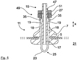
- FIG 5 a second embodiment of the air valve 7 is shown.
- the transmitter 27 fixed to the air valve 7, so that the air valve 7, the temperature sensor 17 and the transmitter 27 form a unit here.
- the transmitting device 27 surrounds the air valve 7 here, for example, with a defined gap distance in the form of a ring and is in contact with a stop 49 of the air valve 7.
- the stop 49 is formed here, for example, by increasing the diameter of the air valve 7.
- a fastening element is provided, embodied here by way of example as a screw nut 51, in particular as a knurled nut, by means of which the transmitting device 27 can be clamped or pressed against the stop 49 on the air valve side.
- the transmission device 27 could also be fixed to the air valve 7 in some other way, for example in a non-positive, positive and/or frictional manner.
- the transmitter device 27 is designed in such a way that the respective sensor contact element 19 of the temperature sensor 17 is in contact with the corresponding transmitter contact element 35 .
- the cables 31 ( 2 ) are therefore not provided here.
- the sensor contact elements 19 are rod-shaped and the transmitter contact elements 35 are plate-shaped.
- a third embodiment of the air valve 7 is shown.
- the transmitter contact elements 35 annular. In this way, the transmitter contact elements 35 and the sensor contact elements 19 can be brought into contact with one another in a particularly reliable manner.
- the truck 1 is coupled to a trailer/semi-trailer 53 so that the truck 1 and the trailer/semi-trailer 53 form a vehicle combination.
- Each vehicle tire 3 of the vehicle combination has the air valve 7 here, as a result of which the temperatures of all vehicle tires 3 of the vehicle combination are measured.
Landscapes
- Engineering & Computer Science (AREA)
- Mechanical Engineering (AREA)
- General Engineering & Computer Science (AREA)
- Radar, Positioning & Navigation (AREA)
- Remote Sensing (AREA)
- Physics & Mathematics (AREA)
- General Physics & Mathematics (AREA)
- Automation & Control Theory (AREA)
- Arrangements For Transmission Of Measured Signals (AREA)
- Regulating Braking Force (AREA)
- Tires In General (AREA)
- Auxiliary Drives, Propulsion Controls, And Safety Devices (AREA)
- Emergency Alarm Devices (AREA)
- Traffic Control Systems (AREA)
Priority Applications (1)
| Application Number | Priority Date | Filing Date | Title |
|---|---|---|---|
| EP22186860.7A EP4119365B1 (de) | 2015-02-12 | 2016-02-04 | Luftventil für fahrzeugreifen |
Applications Claiming Priority (1)
| Application Number | Priority Date | Filing Date | Title |
|---|---|---|---|
| DE102015001803.5A DE102015001803A1 (de) | 2015-02-12 | 2015-02-12 | Verfahren und Vorrichtung zur Unterstützung eines Fahrers eines Fahrzeugs, insbesondere eines Nutzfahrzeugs |
Related Child Applications (2)
| Application Number | Title | Priority Date | Filing Date |
|---|---|---|---|
| EP22186860.7A Division EP4119365B1 (de) | 2015-02-12 | 2016-02-04 | Luftventil für fahrzeugreifen |
| EP22186860.7A Division-Into EP4119365B1 (de) | 2015-02-12 | 2016-02-04 | Luftventil für fahrzeugreifen |
Publications (2)
| Publication Number | Publication Date |
|---|---|
| EP3056362A1 EP3056362A1 (de) | 2016-08-17 |
| EP3056362B1 true EP3056362B1 (de) | 2022-09-14 |
Family
ID=55310618
Family Applications (2)
| Application Number | Title | Priority Date | Filing Date |
|---|---|---|---|
| EP16000273.9A Active EP3056362B1 (de) | 2015-02-12 | 2016-02-04 | Verfahren und vorrichtung zur unterstützung eines fahrers eines fahrzeugs, insbesondere eines nutzfahrzeugs |
| EP22186860.7A Active EP4119365B1 (de) | 2015-02-12 | 2016-02-04 | Luftventil für fahrzeugreifen |
Family Applications After (1)
| Application Number | Title | Priority Date | Filing Date |
|---|---|---|---|
| EP22186860.7A Active EP4119365B1 (de) | 2015-02-12 | 2016-02-04 | Luftventil für fahrzeugreifen |
Country Status (9)
| Country | Link |
|---|---|
| US (1) | US9963003B2 (pl) |
| EP (2) | EP3056362B1 (pl) |
| CN (4) | CN112776544B (pl) |
| AU (1) | AU2016200658B2 (pl) |
| BR (1) | BR102016002930B1 (pl) |
| DE (1) | DE102015001803A1 (pl) |
| HU (1) | HUE060445T2 (pl) |
| PL (1) | PL3056362T3 (pl) |
| RU (1) | RU2705886C2 (pl) |
Families Citing this family (10)
| Publication number | Priority date | Publication date | Assignee | Title |
|---|---|---|---|---|
| BE1022408B1 (nl) * | 2014-09-03 | 2016-03-24 | Cnh Industrial Belgium Nv | Controller voor een voertuig |
| US10147246B2 (en) * | 2016-06-09 | 2018-12-04 | Magna Electronics Inc. | Wheel bolt torque monitoring system for vehicle |
| DE102016011508A1 (de) * | 2016-09-21 | 2018-03-22 | Knorr-Bremse Systeme für Nutzfahrzeuge GmbH | Schraubenkompressorsystem für ein Nutzfahrzeug |
| CN112512842A (zh) * | 2018-07-31 | 2021-03-16 | 伊夸莱尔系统公司 | 数字轮端组件温度监测系统 |
| FR3089867B1 (fr) * | 2018-12-13 | 2020-11-20 | Continental Automotive France | Procédé de détection d’un risque d’éclatement d’un pneu |
| JP7238410B2 (ja) | 2019-01-09 | 2023-03-14 | 横浜ゴム株式会社 | タイヤ故障予知システム、タイヤ故障予知方法 |
| US11865875B2 (en) * | 2020-08-18 | 2024-01-09 | The Goodyear Tire & Rubber Company | Tire high temperature forecasting system |
| CN112918196B (zh) * | 2021-01-29 | 2023-08-22 | 浙江吉利控股集团有限公司 | 一种轮胎状态安全预警方法、系统及车辆 |
| US12403852B2 (en) * | 2021-09-27 | 2025-09-02 | Grote Industries, Inc. | Light strip communication system |
| US11589160B1 (en) * | 2022-05-16 | 2023-02-21 | Geotab Inc. | Systems and methods for controlling audio output in a telematics system |
Citations (2)
| Publication number | Priority date | Publication date | Assignee | Title |
|---|---|---|---|---|
| US6167900B1 (en) * | 1999-02-12 | 2001-01-02 | David Norman Laird | Valve stem with slidable, rotatable air-tight coupling for removably attachable devices |
| US20070044552A1 (en) * | 2005-08-31 | 2007-03-01 | Teng-Wen Huang | Tire pressure detector |
Family Cites Families (41)
| Publication number | Priority date | Publication date | Assignee | Title |
|---|---|---|---|---|
| US3934223A (en) * | 1973-12-04 | 1976-01-20 | Safety Research & Engineering Corporation | Tire pressure warning system |
| IT1005242B (it) * | 1973-12-12 | 1976-08-20 | Pirelli | Dispositivo con valvola d aria a supporto in plastica atta all im missione d aria e alla segnalazio ne del valore d una grandezza fi sica all interno d un pneumatico |
| DE3884506T2 (de) * | 1987-07-23 | 1994-05-11 | Bridgestone Corp | Reifenprüfeinrichtung. |
| DE4303583C2 (de) * | 1993-02-08 | 1996-02-22 | Alpha Beta Electronics Ag | Ventil mit einer Einrichtung zur Erzeugung eines drahtlos übermittelbaren Druckabnahme-Anzeigesignals für Fahrzeugreifen |
| ATE235385T1 (de) * | 1995-09-01 | 2003-04-15 | Fast Air Sl | Verfahren und system zur messung und einstellung von reifendruck |
| JP3354857B2 (ja) * | 1997-12-17 | 2002-12-09 | 太平洋工業株式会社 | タイヤ空気圧警報装置 |
| US6101870A (en) * | 1997-11-10 | 2000-08-15 | Pacific Industrial Co., Ltd. | Tire air pressure monitoring device using the wheel or a coil wound around the stem as the transmitter antenna |
| GB9811154D0 (en) * | 1998-05-22 | 1998-07-22 | Automotive Technologies Limite | A remote tyre pressure monitoring system |
| US6034596A (en) * | 1998-09-15 | 2000-03-07 | Smith; Julian | Motor vehicle tire pressure and temperature sensing system |
| ES2381940T3 (es) | 2000-07-26 | 2012-06-01 | Bridgestone Americas Tire Operations, Llc | Sistema electrónico de gestión de neumáticos |
| KR20070118707A (ko) | 2000-09-21 | 2007-12-17 | 아메리칸 캘카어 인코포레이티드 | 차량을 효과적으로 그리고 안전하게 운전하는 기술 |
| CN2479317Y (zh) * | 2001-04-25 | 2002-02-27 | 赵国平 | 轮胎防爆气门嘴 |
| EP1279526B1 (de) * | 2001-07-24 | 2008-10-08 | TÜV Automotive GmbH Unternehmensgruppe TÜV Süddeutschland | Verfahren und System zum Überwachen des Betriebs eines Fahrzeugreifens sowie Fahrzeugreifen |
| DE10218781A1 (de) | 2002-04-26 | 2003-11-13 | Tuev Automotive Gmbh | Auf einer Felge montierbarer Luftreifen, Sensornetz, Umdrehungsmesseinheit und Fahrzeugüberwachungssystem |
| WO2004000581A1 (en) | 2002-06-20 | 2003-12-31 | Bridgestone/Firestone North American Tire, Llc | Device for detecting overheated tires |
| DE10236140A1 (de) | 2002-08-07 | 2004-02-19 | Schefenacker Vision Systems Germany Gmbh & Co. Kg | Vorrichtung zum Messen des Druckes und/oder der Lufttemperatur eines Reifens |
| EP1544002B1 (en) * | 2002-08-12 | 2010-12-29 | Bridgestone Corporation | Method, device, and recording medium where program is recorded, for deciding residual travel life and end of life of run-flat tire that continues traveling in run-flat condition |
| JP3997864B2 (ja) * | 2002-08-14 | 2007-10-24 | トヨタ自動車株式会社 | 車輪状態取得装置および車両状態取得装置 |
| JP2004196032A (ja) * | 2002-12-16 | 2004-07-15 | Hino Motors Ltd | タイヤの異常温度警報装置 |
| CN100503284C (zh) | 2003-02-14 | 2009-06-24 | 王正键 | 汽车轮胎安全监控与爆胎汽车方向防偏系统及工作方法 |
| WO2004091943A1 (ja) * | 2003-04-15 | 2004-10-28 | The Yokohama Rubber Co., Ltd. | タイヤ警報装置 |
| JP4276522B2 (ja) * | 2003-11-07 | 2009-06-10 | 株式会社ブリヂストン | タイヤセンサ装置 |
| JP2005186658A (ja) * | 2003-12-24 | 2005-07-14 | Chuo Motor Wheel Co Ltd | タイヤ空気圧検知手段を備えたタイヤバルブ及び該バルブを備えたタイヤ空気圧検知装置 |
| JP2007050735A (ja) | 2005-08-17 | 2007-03-01 | Hino Motors Ltd | 車両火災警報装置 |
| JP4435114B2 (ja) * | 2006-05-31 | 2010-03-17 | トヨタ自動車株式会社 | 車両用車輪のタイヤリスク判定装置 |
| KR100802961B1 (ko) * | 2006-11-28 | 2008-02-14 | 현대자동차주식회사 | 차량용 타이어 히트 세퍼레이션 방지장치 |
| JP2010006217A (ja) * | 2008-06-26 | 2010-01-14 | Toyota Motor Corp | 車両制御装置 |
| JP5067287B2 (ja) * | 2008-07-03 | 2012-11-07 | 横浜ゴム株式会社 | 車両の運転状態監視方法及びその装置 |
| IT1390937B1 (it) * | 2008-08-06 | 2011-10-27 | Ferrari Spa | Metodo e dispositivo di controllo di un veicolo per segnalare il raggiungimento della temperatura ottimale di funzionamento dei pneumatici e dei freni |
| JP2012500148A (ja) * | 2008-08-21 | 2012-01-05 | コルファックス,ウォリック,イアン | 圧力センサを具える空気タイヤ用バルブ装置 |
| KR101137813B1 (ko) * | 2009-04-01 | 2012-04-18 | 씨트론 주식회사 | 타이어 압력 모니터링 시스템 및 그의 타이어센서 |
| CN201472086U (zh) | 2009-08-25 | 2010-05-19 | 中国矿业大学(北京) | 车辆轮胎内温度压力自动监测系统 |
| CN201506219U (zh) * | 2009-08-31 | 2010-06-16 | 比亚迪股份有限公司 | 一种气嘴及包含该气嘴的胎压监测系统 |
| CN102809380A (zh) * | 2011-05-30 | 2012-12-05 | 昆达电脑科技(昆山)有限公司 | 导航装置与导航方法 |
| DE102011050985A1 (de) * | 2011-06-09 | 2012-12-13 | Huf Hülsbeck & Fürst Gmbh & Co. Kg | Verfahren zum Betreiben einer Reifendrucküberwachungseinheit und Reifendrucküberwachungseinheit |
| CN203126409U (zh) | 2013-03-18 | 2013-08-14 | 山东交通学院 | 一种基于红外测温的轮胎压力监测防爆装置 |
| CN203093632U (zh) | 2013-03-27 | 2013-07-31 | 黑龙江东方学院 | 车辆行驶状态下轮胎温度监测系统 |
| CN203172364U (zh) | 2013-04-09 | 2013-09-04 | 丛林 | 一种新型轮胎防爆预警装置 |
| CN203358231U (zh) | 2013-06-13 | 2013-12-25 | 天津云视科技发展有限公司 | 一种应用声表面波技术的汽车轮胎温度实时监测装置 |
| KR101504008B1 (ko) | 2013-06-14 | 2015-03-18 | 주식회사 콕스 | 열상 카메라를 이용한 타이어 과열 경보 및 냉각 시스템 및 그 방법 |
| CN104228482B (zh) * | 2013-06-24 | 2016-11-09 | 上海工程技术大学 | 基于胎压监测的行车安全控制系统 |
-
2015
- 2015-02-12 DE DE102015001803.5A patent/DE102015001803A1/de not_active Ceased
-
2016
- 2016-02-03 AU AU2016200658A patent/AU2016200658B2/en active Active
- 2016-02-04 HU HUE16000273A patent/HUE060445T2/hu unknown
- 2016-02-04 PL PL16000273.9T patent/PL3056362T3/pl unknown
- 2016-02-04 EP EP16000273.9A patent/EP3056362B1/de active Active
- 2016-02-04 EP EP22186860.7A patent/EP4119365B1/de active Active
- 2016-02-11 RU RU2016104508A patent/RU2705886C2/ru active
- 2016-02-11 BR BR102016002930-9A patent/BR102016002930B1/pt active IP Right Grant
- 2016-02-11 US US15/041,686 patent/US9963003B2/en active Active
- 2016-02-15 CN CN202110216190.0A patent/CN112776544B/zh active Active
- 2016-02-15 CN CN201610085711.2A patent/CN105882332B/zh active Active
- 2016-02-15 CN CN202110216488.1A patent/CN112776545A/zh active Pending
- 2016-02-15 CN CN202110216189.8A patent/CN112776543A/zh active Pending
Patent Citations (2)
| Publication number | Priority date | Publication date | Assignee | Title |
|---|---|---|---|---|
| US6167900B1 (en) * | 1999-02-12 | 2001-01-02 | David Norman Laird | Valve stem with slidable, rotatable air-tight coupling for removably attachable devices |
| US20070044552A1 (en) * | 2005-08-31 | 2007-03-01 | Teng-Wen Huang | Tire pressure detector |
Also Published As
| Publication number | Publication date |
|---|---|
| PL3056362T3 (pl) | 2022-12-19 |
| CN112776544A (zh) | 2021-05-11 |
| DE102015001803A1 (de) | 2016-08-18 |
| RU2016104508A3 (pl) | 2019-09-06 |
| CN112776545A (zh) | 2021-05-11 |
| HUE060445T2 (hu) | 2023-02-28 |
| CN112776543A (zh) | 2021-05-11 |
| EP3056362A1 (de) | 2016-08-17 |
| CN105882332B (zh) | 2021-03-12 |
| US20160159173A1 (en) | 2016-06-09 |
| EP4119365A1 (de) | 2023-01-18 |
| BR102016002930B1 (pt) | 2021-10-19 |
| RU2016104508A (ru) | 2017-08-16 |
| AU2016200658A1 (en) | 2016-09-01 |
| CN112776544B (zh) | 2023-05-30 |
| CN105882332A (zh) | 2016-08-24 |
| EP4119365B1 (de) | 2025-12-10 |
| EP4119365C0 (de) | 2025-12-10 |
| BR102016002930A2 (pt) | 2016-10-11 |
| RU2705886C2 (ru) | 2019-11-12 |
| AU2016200658B2 (en) | 2019-11-28 |
| US9963003B2 (en) | 2018-05-08 |
Similar Documents
| Publication | Publication Date | Title |
|---|---|---|
| EP4119365B1 (de) | Luftventil für fahrzeugreifen | |
| EP3878679B1 (de) | Verfahren und vorrichtung zur unterstützung eines fahrers eines fahrzeugs, insbesondere eines nutzfahrzeugs | |
| EP0045401A2 (de) | Übertragungsverfahren für veränderliche Messwerte von Fahrzeug-Rädern | |
| DE102006038059B4 (de) | Automatisches Nachweisen eines gelösten Fern-Reifendrucksensors | |
| DE10316993B4 (de) | System zum Überwachen des Sitzes eines Gurtes um ein Objekt | |
| EP3814735B1 (de) | Verfahren zum überwachen von mittels zugelementen und vorzugsweise spanngurten arbeitenden transportsicherungen | |
| DE102004001250B4 (de) | Vorrichtung und Verfahren zur Ermittlung der Seitenposition von Rädern | |
| DE10144361A1 (de) | Verfahren und System zum Detektrieren eines Druckabfalls in einem Reifen | |
| DE60205272T2 (de) | Verfahren zur schätzung der lufttemperatur im innenraum eines reifens und anwendung zum erfassen von anomalitäten im notlaufbetrieb | |
| DE102008014448A1 (de) | Intelligente Enddruckwächtereinheit | |
| EP3560736B1 (de) | Verfahren zum übertragen von daten eines reifenmoduls zu einem zentralen datenserver | |
| DE19723037A1 (de) | Reifendruck-Überwachungssystem | |
| DE102011006646B4 (de) | Reifenfülldruck-Kontrollsystem in Kraftfahrzeugen | |
| DE102015002715B4 (de) | Verfahren und System zum Feststellen des Funktionsstatus bei einer Spoilervorrichtung eines Fahrzeugs | |
| WO2007147675A1 (de) | Verfahren zur messung des luftdrucks in einem fahrzeugreifen | |
| DE102009057579A1 (de) | Luftdruckanpassung zum Einstellen eines Latsch eines Reifens | |
| EP1963109B1 (de) | Radnabenanordnung | |
| DE102006016476A1 (de) | Wälzlager mit Sensor | |
| DE102018005791A1 (de) | Verfahren zum Betrieb eines Reifendrucksensors eines Fahrzeugs | |
| EP2100756B1 (de) | Vorrichtung und Verfahren zur Temperaturmessung an Fahrzeug-Luftreifen | |
| DE102008021153A1 (de) | Vorrichtung und Verfahren zum automatischen oder semiautomatischen Einparken | |
| EP2995919B1 (de) | Sicherheitsvorrichtung für eine achswelle mit zentralmutter und verfahren zur kontrolle des anzugs der zentralmutter | |
| DE102018220787A1 (de) | Verfahren und Steuergerät zur Betätigung einer Planenhubeinrichtung | |
| DE19503250B4 (de) | Niveauregelvorrichtung für Radaufhängungen von Kraftfahrzeugen | |
| DE102020202098B4 (de) | Anpassung eines Reifenfülldrucks bei Doppelbereifung |
Legal Events
| Date | Code | Title | Description |
|---|---|---|---|
| PUAI | Public reference made under article 153(3) epc to a published international application that has entered the european phase |
Free format text: ORIGINAL CODE: 0009012 |
|
| AK | Designated contracting states |
Kind code of ref document: A1 Designated state(s): AL AT BE BG CH CY CZ DE DK EE ES FI FR GB GR HR HU IE IS IT LI LT LU LV MC MK MT NL NO PL PT RO RS SE SI SK SM TR |
|
| AX | Request for extension of the european patent |
Extension state: BA ME |
|
| STAA | Information on the status of an ep patent application or granted ep patent |
Free format text: STATUS: REQUEST FOR EXAMINATION WAS MADE |
|
| 17P | Request for examination filed |
Effective date: 20170217 |
|
| RBV | Designated contracting states (corrected) |
Designated state(s): AL AT BE BG CH CY CZ DE DK EE ES FI FR GB GR HR HU IE IS IT LI LT LU LV MC MK MT NL NO PL PT RO RS SE SI SK SM TR |
|
| RAP1 | Party data changed (applicant data changed or rights of an application transferred) |
Owner name: MAN TRUCK & BUS SE |
|
| STAA | Information on the status of an ep patent application or granted ep patent |
Free format text: STATUS: EXAMINATION IS IN PROGRESS |
|
| 17Q | First examination report despatched |
Effective date: 20201125 |
|
| GRAP | Despatch of communication of intention to grant a patent |
Free format text: ORIGINAL CODE: EPIDOSNIGR1 |
|
| STAA | Information on the status of an ep patent application or granted ep patent |
Free format text: STATUS: GRANT OF PATENT IS INTENDED |
|
| INTG | Intention to grant announced |
Effective date: 20220325 |
|
| GRAS | Grant fee paid |
Free format text: ORIGINAL CODE: EPIDOSNIGR3 |
|
| GRAA | (expected) grant |
Free format text: ORIGINAL CODE: 0009210 |
|
| STAA | Information on the status of an ep patent application or granted ep patent |
Free format text: STATUS: THE PATENT HAS BEEN GRANTED |
|
| AK | Designated contracting states |
Kind code of ref document: B1 Designated state(s): AL AT BE BG CH CY CZ DE DK EE ES FI FR GB GR HR HU IE IS IT LI LT LU LV MC MK MT NL NO PL PT RO RS SE SI SK SM TR |
|
| REG | Reference to a national code |
Ref country code: GB Ref legal event code: FG4D Free format text: NOT ENGLISH |
|
| REG | Reference to a national code |
Ref country code: CH Ref legal event code: EP |
|
| REG | Reference to a national code |
Ref country code: DE Ref legal event code: R096 Ref document number: 502016015269 Country of ref document: DE |
|
| REG | Reference to a national code |
Ref country code: IE Ref legal event code: FG4D Free format text: LANGUAGE OF EP DOCUMENT: GERMAN |
|
| REG | Reference to a national code |
Ref country code: AT Ref legal event code: REF Ref document number: 1518486 Country of ref document: AT Kind code of ref document: T Effective date: 20221015 |
|
| REG | Reference to a national code |
Ref country code: SE Ref legal event code: TRGR |
|
| REG | Reference to a national code |
Ref country code: NL Ref legal event code: FP |
|
| REG | Reference to a national code |
Ref country code: LT Ref legal event code: MG9D |
|
| PG25 | Lapsed in a contracting state [announced via postgrant information from national office to epo] |
Ref country code: RS Free format text: LAPSE BECAUSE OF FAILURE TO SUBMIT A TRANSLATION OF THE DESCRIPTION OR TO PAY THE FEE WITHIN THE PRESCRIBED TIME-LIMIT Effective date: 20220914 Ref country code: NO Free format text: LAPSE BECAUSE OF FAILURE TO SUBMIT A TRANSLATION OF THE DESCRIPTION OR TO PAY THE FEE WITHIN THE PRESCRIBED TIME-LIMIT Effective date: 20221214 Ref country code: LV Free format text: LAPSE BECAUSE OF FAILURE TO SUBMIT A TRANSLATION OF THE DESCRIPTION OR TO PAY THE FEE WITHIN THE PRESCRIBED TIME-LIMIT Effective date: 20220914 Ref country code: LT Free format text: LAPSE BECAUSE OF FAILURE TO SUBMIT A TRANSLATION OF THE DESCRIPTION OR TO PAY THE FEE WITHIN THE PRESCRIBED TIME-LIMIT Effective date: 20220914 Ref country code: FI Free format text: LAPSE BECAUSE OF FAILURE TO SUBMIT A TRANSLATION OF THE DESCRIPTION OR TO PAY THE FEE WITHIN THE PRESCRIBED TIME-LIMIT Effective date: 20220914 |
|
| PG25 | Lapsed in a contracting state [announced via postgrant information from national office to epo] |
Ref country code: HR Free format text: LAPSE BECAUSE OF FAILURE TO SUBMIT A TRANSLATION OF THE DESCRIPTION OR TO PAY THE FEE WITHIN THE PRESCRIBED TIME-LIMIT Effective date: 20220914 Ref country code: GR Free format text: LAPSE BECAUSE OF FAILURE TO SUBMIT A TRANSLATION OF THE DESCRIPTION OR TO PAY THE FEE WITHIN THE PRESCRIBED TIME-LIMIT Effective date: 20221215 |
|
| REG | Reference to a national code |
Ref country code: HU Ref legal event code: AG4A Ref document number: E060445 Country of ref document: HU |
|
| PG25 | Lapsed in a contracting state [announced via postgrant information from national office to epo] |
Ref country code: SM Free format text: LAPSE BECAUSE OF FAILURE TO SUBMIT A TRANSLATION OF THE DESCRIPTION OR TO PAY THE FEE WITHIN THE PRESCRIBED TIME-LIMIT Effective date: 20220914 Ref country code: RO Free format text: LAPSE BECAUSE OF FAILURE TO SUBMIT A TRANSLATION OF THE DESCRIPTION OR TO PAY THE FEE WITHIN THE PRESCRIBED TIME-LIMIT Effective date: 20220914 Ref country code: PT Free format text: LAPSE BECAUSE OF FAILURE TO SUBMIT A TRANSLATION OF THE DESCRIPTION OR TO PAY THE FEE WITHIN THE PRESCRIBED TIME-LIMIT Effective date: 20230116 Ref country code: ES Free format text: LAPSE BECAUSE OF FAILURE TO SUBMIT A TRANSLATION OF THE DESCRIPTION OR TO PAY THE FEE WITHIN THE PRESCRIBED TIME-LIMIT Effective date: 20220914 Ref country code: CZ Free format text: LAPSE BECAUSE OF FAILURE TO SUBMIT A TRANSLATION OF THE DESCRIPTION OR TO PAY THE FEE WITHIN THE PRESCRIBED TIME-LIMIT Effective date: 20220914 |
|
| PG25 | Lapsed in a contracting state [announced via postgrant information from national office to epo] |
Ref country code: SK Free format text: LAPSE BECAUSE OF FAILURE TO SUBMIT A TRANSLATION OF THE DESCRIPTION OR TO PAY THE FEE WITHIN THE PRESCRIBED TIME-LIMIT Effective date: 20220914 Ref country code: IS Free format text: LAPSE BECAUSE OF FAILURE TO SUBMIT A TRANSLATION OF THE DESCRIPTION OR TO PAY THE FEE WITHIN THE PRESCRIBED TIME-LIMIT Effective date: 20230114 Ref country code: EE Free format text: LAPSE BECAUSE OF FAILURE TO SUBMIT A TRANSLATION OF THE DESCRIPTION OR TO PAY THE FEE WITHIN THE PRESCRIBED TIME-LIMIT Effective date: 20220914 |
|
| REG | Reference to a national code |
Ref country code: DE Ref legal event code: R097 Ref document number: 502016015269 Country of ref document: DE |
|
| PG25 | Lapsed in a contracting state [announced via postgrant information from national office to epo] |
Ref country code: AL Free format text: LAPSE BECAUSE OF FAILURE TO SUBMIT A TRANSLATION OF THE DESCRIPTION OR TO PAY THE FEE WITHIN THE PRESCRIBED TIME-LIMIT Effective date: 20220914 |
|
| PLBE | No opposition filed within time limit |
Free format text: ORIGINAL CODE: 0009261 |
|
| STAA | Information on the status of an ep patent application or granted ep patent |
Free format text: STATUS: NO OPPOSITION FILED WITHIN TIME LIMIT |
|
| PG25 | Lapsed in a contracting state [announced via postgrant information from national office to epo] |
Ref country code: DK Free format text: LAPSE BECAUSE OF FAILURE TO SUBMIT A TRANSLATION OF THE DESCRIPTION OR TO PAY THE FEE WITHIN THE PRESCRIBED TIME-LIMIT Effective date: 20220914 |
|
| 26N | No opposition filed |
Effective date: 20230615 |
|
| PG25 | Lapsed in a contracting state [announced via postgrant information from national office to epo] |
Ref country code: SI Free format text: LAPSE BECAUSE OF FAILURE TO SUBMIT A TRANSLATION OF THE DESCRIPTION OR TO PAY THE FEE WITHIN THE PRESCRIBED TIME-LIMIT Effective date: 20220914 |
|
| PG25 | Lapsed in a contracting state [announced via postgrant information from national office to epo] |
Ref country code: MC Free format text: LAPSE BECAUSE OF FAILURE TO SUBMIT A TRANSLATION OF THE DESCRIPTION OR TO PAY THE FEE WITHIN THE PRESCRIBED TIME-LIMIT Effective date: 20220914 |
|
| REG | Reference to a national code |
Ref country code: CH Ref legal event code: PL |
|
| REG | Reference to a national code |
Ref country code: BE Ref legal event code: MM Effective date: 20230228 |
|
| GBPC | Gb: european patent ceased through non-payment of renewal fee |
Effective date: 20230204 |
|
| PG25 | Lapsed in a contracting state [announced via postgrant information from national office to epo] |
Ref country code: LU Free format text: LAPSE BECAUSE OF NON-PAYMENT OF DUE FEES Effective date: 20230204 Ref country code: LI Free format text: LAPSE BECAUSE OF NON-PAYMENT OF DUE FEES Effective date: 20230228 Ref country code: CH Free format text: LAPSE BECAUSE OF NON-PAYMENT OF DUE FEES Effective date: 20230228 |
|
| REG | Reference to a national code |
Ref country code: IE Ref legal event code: MM4A |
|
| PG25 | Lapsed in a contracting state [announced via postgrant information from national office to epo] |
Ref country code: GB Free format text: LAPSE BECAUSE OF NON-PAYMENT OF DUE FEES Effective date: 20230204 |
|
| PG25 | Lapsed in a contracting state [announced via postgrant information from national office to epo] |
Ref country code: IE Free format text: LAPSE BECAUSE OF NON-PAYMENT OF DUE FEES Effective date: 20230204 Ref country code: GB Free format text: LAPSE BECAUSE OF NON-PAYMENT OF DUE FEES Effective date: 20230204 |
|
| PG25 | Lapsed in a contracting state [announced via postgrant information from national office to epo] |
Ref country code: BE Free format text: LAPSE BECAUSE OF NON-PAYMENT OF DUE FEES Effective date: 20230228 |
|
| REG | Reference to a national code |
Ref country code: AT Ref legal event code: MM01 Ref document number: 1518486 Country of ref document: AT Kind code of ref document: T Effective date: 20230204 |
|
| PG25 | Lapsed in a contracting state [announced via postgrant information from national office to epo] |
Ref country code: AT Free format text: LAPSE BECAUSE OF NON-PAYMENT OF DUE FEES Effective date: 20230204 |
|
| PG25 | Lapsed in a contracting state [announced via postgrant information from national office to epo] |
Ref country code: AT Free format text: LAPSE BECAUSE OF NON-PAYMENT OF DUE FEES Effective date: 20230204 |
|
| PG25 | Lapsed in a contracting state [announced via postgrant information from national office to epo] |
Ref country code: BG Free format text: LAPSE BECAUSE OF FAILURE TO SUBMIT A TRANSLATION OF THE DESCRIPTION OR TO PAY THE FEE WITHIN THE PRESCRIBED TIME-LIMIT Effective date: 20220914 |
|
| PG25 | Lapsed in a contracting state [announced via postgrant information from national office to epo] |
Ref country code: BG Free format text: LAPSE BECAUSE OF FAILURE TO SUBMIT A TRANSLATION OF THE DESCRIPTION OR TO PAY THE FEE WITHIN THE PRESCRIBED TIME-LIMIT Effective date: 20220914 |
|
| PG25 | Lapsed in a contracting state [announced via postgrant information from national office to epo] |
Ref country code: CY Free format text: LAPSE BECAUSE OF FAILURE TO SUBMIT A TRANSLATION OF THE DESCRIPTION OR TO PAY THE FEE WITHIN THE PRESCRIBED TIME-LIMIT; INVALID AB INITIO Effective date: 20160204 |
|
| PGFP | Annual fee paid to national office [announced via postgrant information from national office to epo] |
Ref country code: NL Payment date: 20260220 Year of fee payment: 11 |
|
| PGFP | Annual fee paid to national office [announced via postgrant information from national office to epo] |
Ref country code: HU Payment date: 20260211 Year of fee payment: 11 |
|
| PGFP | Annual fee paid to national office [announced via postgrant information from national office to epo] |
Ref country code: SE Payment date: 20260223 Year of fee payment: 11 |
|
| PGFP | Annual fee paid to national office [announced via postgrant information from national office to epo] |
Ref country code: DE Payment date: 20260220 Year of fee payment: 11 |
|
| PGFP | Annual fee paid to national office [announced via postgrant information from national office to epo] |
Ref country code: IT Payment date: 20260220 Year of fee payment: 11 |
|
| PGFP | Annual fee paid to national office [announced via postgrant information from national office to epo] |
Ref country code: FR Payment date: 20260224 Year of fee payment: 11 |
|
| PGFP | Annual fee paid to national office [announced via postgrant information from national office to epo] |
Ref country code: TR Payment date: 20260123 Year of fee payment: 11 |
|
| PGFP | Annual fee paid to national office [announced via postgrant information from national office to epo] |
Ref country code: PL Payment date: 20260126 Year of fee payment: 11 |