US10147246B2 - Wheel bolt torque monitoring system for vehicle - Google Patents
Wheel bolt torque monitoring system for vehicle Download PDFInfo
- Publication number
- US10147246B2 US10147246B2 US15/614,926 US201715614926A US10147246B2 US 10147246 B2 US10147246 B2 US 10147246B2 US 201715614926 A US201715614926 A US 201715614926A US 10147246 B2 US10147246 B2 US 10147246B2
- Authority
- US
- United States
- Prior art keywords
- torque
- bolt
- wheel
- monitoring system
- vehicle
- Prior art date
- Legal status (The legal status is an assumption and is not a legal conclusion. Google has not performed a legal analysis and makes no representation as to the accuracy of the status listed.)
- Active
Links
- 238000012544 monitoring process Methods 0.000 title claims abstract description 47
- 238000000034 method Methods 0.000 claims abstract description 4
- 230000003247 decreasing effect Effects 0.000 claims 11
- 238000004148 unit process Methods 0.000 claims 6
- 238000012545 processing Methods 0.000 description 18
- 238000004891 communication Methods 0.000 description 9
- 230000008901 benefit Effects 0.000 description 3
- 230000000712 assembly Effects 0.000 description 1
- 238000000429 assembly Methods 0.000 description 1
- 230000000981 bystander Effects 0.000 description 1
- 238000011109 contamination Methods 0.000 description 1
- 230000003467 diminishing effect Effects 0.000 description 1
- 238000005516 engineering process Methods 0.000 description 1
- 231100001261 hazardous Toxicity 0.000 description 1
- 238000012986 modification Methods 0.000 description 1
- 230000004048 modification Effects 0.000 description 1
- 238000012552 review Methods 0.000 description 1
- 230000000007 visual effect Effects 0.000 description 1
Images


Classifications
-
- G—PHYSICS
- G07—CHECKING-DEVICES
- G07C—TIME OR ATTENDANCE REGISTERS; REGISTERING OR INDICATING THE WORKING OF MACHINES; GENERATING RANDOM NUMBERS; VOTING OR LOTTERY APPARATUS; ARRANGEMENTS, SYSTEMS OR APPARATUS FOR CHECKING NOT PROVIDED FOR ELSEWHERE
- G07C5/00—Registering or indicating the working of vehicles
- G07C5/08—Registering or indicating performance data other than driving, working, idle, or waiting time, with or without registering driving, working, idle or waiting time
- G07C5/0816—Indicating performance data, e.g. occurrence of a malfunction
-
- B—PERFORMING OPERATIONS; TRANSPORTING
- B60—VEHICLES IN GENERAL
- B60Q—ARRANGEMENT OF SIGNALLING OR LIGHTING DEVICES, THE MOUNTING OR SUPPORTING THEREOF OR CIRCUITS THEREFOR, FOR VEHICLES IN GENERAL
- B60Q9/00—Arrangement or adaptation of signal devices not provided for in one of main groups B60Q1/00 - B60Q7/00, e.g. haptic signalling
-
- B—PERFORMING OPERATIONS; TRANSPORTING
- B60—VEHICLES IN GENERAL
- B60R—VEHICLES, VEHICLE FITTINGS, OR VEHICLE PARTS, NOT OTHERWISE PROVIDED FOR
- B60R1/00—Optical viewing arrangements; Real-time viewing arrangements for drivers or passengers using optical image capturing systems, e.g. cameras or video systems specially adapted for use in or on vehicles
- B60R1/02—Rear-view mirror arrangements
- B60R1/04—Rear-view mirror arrangements mounted inside vehicle
-
- B—PERFORMING OPERATIONS; TRANSPORTING
- B60—VEHICLES IN GENERAL
- B60R—VEHICLES, VEHICLE FITTINGS, OR VEHICLE PARTS, NOT OTHERWISE PROVIDED FOR
- B60R99/00—Subject matter not provided for in other groups of this subclass
-
- G—PHYSICS
- G01—MEASURING; TESTING
- G01C—MEASURING DISTANCES, LEVELS OR BEARINGS; SURVEYING; NAVIGATION; GYROSCOPIC INSTRUMENTS; PHOTOGRAMMETRY OR VIDEOGRAMMETRY
- G01C21/00—Navigation; Navigational instruments not provided for in groups G01C1/00 - G01C19/00
- G01C21/26—Navigation; Navigational instruments not provided for in groups G01C1/00 - G01C19/00 specially adapted for navigation in a road network
- G01C21/34—Route searching; Route guidance
- G01C21/3407—Route searching; Route guidance specially adapted for specific applications
- G01C21/3415—Dynamic re-routing, e.g. recalculating the route when the user deviates from calculated route or after detecting real-time traffic data or accidents
-
- G—PHYSICS
- G07—CHECKING-DEVICES
- G07C—TIME OR ATTENDANCE REGISTERS; REGISTERING OR INDICATING THE WORKING OF MACHINES; GENERATING RANDOM NUMBERS; VOTING OR LOTTERY APPARATUS; ARRANGEMENTS, SYSTEMS OR APPARATUS FOR CHECKING NOT PROVIDED FOR ELSEWHERE
- G07C5/00—Registering or indicating the working of vehicles
- G07C5/006—Indicating maintenance
-
- G—PHYSICS
- G07—CHECKING-DEVICES
- G07C—TIME OR ATTENDANCE REGISTERS; REGISTERING OR INDICATING THE WORKING OF MACHINES; GENERATING RANDOM NUMBERS; VOTING OR LOTTERY APPARATUS; ARRANGEMENTS, SYSTEMS OR APPARATUS FOR CHECKING NOT PROVIDED FOR ELSEWHERE
- G07C5/00—Registering or indicating the working of vehicles
- G07C5/08—Registering or indicating performance data other than driving, working, idle, or waiting time, with or without registering driving, working, idle or waiting time
- G07C5/0808—Diagnosing performance data
-
- B—PERFORMING OPERATIONS; TRANSPORTING
- B60—VEHICLES IN GENERAL
- B60B—VEHICLE WHEELS; CASTORS; AXLES FOR WHEELS OR CASTORS; INCREASING WHEEL ADHESION
- B60B2900/00—Purpose of invention
- B60B2900/30—Increase in
- B60B2900/331—Safety or security
- B60B2900/3312—Safety or security during regular use
-
- B—PERFORMING OPERATIONS; TRANSPORTING
- B60—VEHICLES IN GENERAL
- B60B—VEHICLE WHEELS; CASTORS; AXLES FOR WHEELS OR CASTORS; INCREASING WHEEL ADHESION
- B60B2900/00—Purpose of invention
- B60B2900/30—Increase in
- B60B2900/331—Safety or security
- B60B2900/3316—Safety or security by indicating wear, failure or loss
-
- B—PERFORMING OPERATIONS; TRANSPORTING
- B60—VEHICLES IN GENERAL
- B60B—VEHICLE WHEELS; CASTORS; AXLES FOR WHEELS OR CASTORS; INCREASING WHEEL ADHESION
- B60B3/00—Disc wheels, i.e. wheels with load-supporting disc body
- B60B3/14—Attaching disc body to hub ; Wheel adapters
- B60B3/16—Attaching disc body to hub ; Wheel adapters by bolts or the like
-
- B—PERFORMING OPERATIONS; TRANSPORTING
- B60—VEHICLES IN GENERAL
- B60R—VEHICLES, VEHICLE FITTINGS, OR VEHICLE PARTS, NOT OTHERWISE PROVIDED FOR
- B60R1/00—Optical viewing arrangements; Real-time viewing arrangements for drivers or passengers using optical image capturing systems, e.g. cameras or video systems specially adapted for use in or on vehicles
- B60R1/12—Mirror assemblies combined with other articles, e.g. clocks
- B60R2001/1215—Mirror assemblies combined with other articles, e.g. clocks with information displays
-
- B—PERFORMING OPERATIONS; TRANSPORTING
- B60—VEHICLES IN GENERAL
- B60Y—INDEXING SCHEME RELATING TO ASPECTS CROSS-CUTTING VEHICLE TECHNOLOGY
- B60Y2400/00—Special features of vehicle units
- B60Y2400/30—Sensors
- B60Y2400/307—Torque sensors
-
- G—PHYSICS
- G01—MEASURING; TESTING
- G01C—MEASURING DISTANCES, LEVELS OR BEARINGS; SURVEYING; NAVIGATION; GYROSCOPIC INSTRUMENTS; PHOTOGRAMMETRY OR VIDEOGRAMMETRY
- G01C21/00—Navigation; Navigational instruments not provided for in groups G01C1/00 - G01C19/00
- G01C21/26—Navigation; Navigational instruments not provided for in groups G01C1/00 - G01C19/00 specially adapted for navigation in a road network
- G01C21/34—Route searching; Route guidance
Definitions
- the present invention relates generally to a vehicle tire monitoring system.
- the present invention provides a wheel bolt torque monitoring system that monitors the torque on the lug nuts or bolts that hold the wheels at the corner assemblies of a vehicle. When the system determines that one or more of the fasteners is getting loose, an alert is generated to alert the driver or occupant or service entity of a potentially hazardous condition.
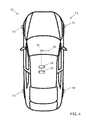
- FIG. 1 is a plan view of a vehicle with a torque monitoring system in accordance with the present invention
- FIG. 2 is a perspective view of a known torque sensor that senses torque at the head of a bolt
- FIG. 3 is a sectional view of a wheel attached to a drum via bolts that are electrically connected to a transmitting device at the drum that communicates torque data to a processing unit in accordance with the present invention
- FIG. 4 is a plan view of a vehicle with a torque monitoring system in accordance with an optional configuration of the present invention, shown with a smart phone 21 attached to or connected to or in communication with the processing and control unit (PU) 16 that is wirelessly connected with the sending electronic devices 14 ; and
- PU processing and control unit
- FIG. 5 is a chart of a tire bolt torque monitored by the system of the present invention, showing that torque loosening quotients may increase over time and, as indicated, the system may output four (or more or less) alerts or warnings with increasing severity of bolt torque loss over time, with the system generating the warnings via displaying text alerts such as shown in FIG. 5 and/or via audible alerts.
- a vehicle 10 includes a torque monitoring system 12 that includes a plurality of torque sensors (such as a torque sensor at each of at least four bolts at each wheel) and a transmitter or sending device 14 at the wheels of the vehicle ( FIG. 1 ).
- the sensors monitor the torque at the wheel bolts and the transmitter 14 transmits data or information to a control 16 of the system. Responsive to a determination of a torque falling below a threshold torque level, the control may generate an alert to the driver of the vehicle, such as at a display 18 at a mirror assembly 20 of the vehicle.
- the mounting torque of several or all of the bolts of the vehicle's wheels may be monitored by using torque measuring tire bolts.
- the electrical interface 26 of a tire bolt 24 according the present invention may not be at the head but at the screw far end side.
- the electrical interface may conduct to a counter plug embedded at the end of the thread of the wheel drum 28 (or wheel saddle or corner assembly) that the bolts gets screwed or threaded into.
- the bolts' electrical interfaces may be conducted to a processing and data sending electronics device (ED) 14 at the wheel drum or corner assembly.
- ED processing and data sending electronics device
- Each wheel may include a respective data sending electronics device.
- the data sending electronics devices may send the status of the torque of the bolts of each wheel to a central receiving, processing and control unit (PU) 16 wirelessly (via Bluetooth, WiFi, NTSC, or such standards).
- the processing unit 16 may be connected to a communication or network bus (such as a CAN bus or the like) of the vehicle or other physical data line or vehicle bus (non-wirelessly).
- the processing unit may be vehicle inherent (such as already existing in the vehicle for other purposes).
- the signal processing may take place in the data sending electronics devices or in the processing unit or in a main processing system of the vehicle, preferably the processing is done centralized in the processing unit.
- the data processing may optionally take place fully on the optional aftermarket device or smart phone or partially on the optional aftermarket device or smart phone and partially on the vehicle inherent processing unit 16 .
- the processing unit may process whether a (one or more) bolt has reached a certain minimal torque when being mounted newly and may monitor whether a bolt is losing torque over a longer period of time or rapidly losing torque when in use.
- the system may optionally have algorithms to compensate for the torque sensor's temperature drift or tolerance band to prevent the system from providing false positive warnings to the driver.
- the system may generate an alarm or message which brings the malfunctioning bolt mounting to the vehicle driver's or owner's attention, who then may stop the vehicle to inspect the vehicle's wheel bolts.
- the system may generate an alert to the vehicle owner or service entity so the vehicle is brought in for service. If the torque is determined to be below an “urgent” low torque, the system may generate an output so the vehicle is autonomously driven to a service station or facility or is pulled over and stopped.
- the system may also monitor the ratio at which one or multiple tire bolts are losing torque. There may be thresholds of torque losing or loosening quotients (torque per hour or torque per mile) in percentage or calculated absolute values which may trigger warning levels of the severity of losing tire bolt torque, such as shown in the example of FIG. 5 . As shown in FIG. 5 , the system may prompt to the driver to “Enter a repair shop soon” or to “emergency stop” depending on the determined tire bolt torque status.
- the system thus can provide an alert that one or more bolts are at an improper torque level.
- the system may generate an alert indicating that an under-torqued bolt has been determined, without any further information about the determined bolt location.
- the system may generate an alert indicating that a particular wheel has an under-torqued bolt, or optionally, the system may generate an alert indicating the particular under-torqued bolt at a particular wheel.
- the system according the invention may have means to detect whether the electrical interface is still connected to the tire bolt. This may happen by distinguishing the electrical resistance, where an open circuit may lead to a conclusion of a “lost bolt.” When the torque is essentially at zero but the electrical interface 26 (connector) still detects the presence of the bolt, the system according the invention may conclude that the tire is not fully fixed any more but “loose.” The system may prompt the appropriate alerts or warnings to the driver.
- the vehicle owner may be different from the driver.
- the owner may be informed or alerted via a UMTS connection, optionally to his or her smartphone.
- the message or alarm or alert to the driver may be acoustic or audible, or haptic or visual, such as via a display device 18 .
- the monitoring system may provide alarms or messages when a bolt has initially lost some (a defined amount of) torque but still has sufficient torque to retain the wheel and tire at the vehicle.
- a wheel bolt loses torque mostly due to under or over torqueing the bolt when the wheel and tire are mounted at the vehicle.
- under-torqued the bolt can turn when vibrating, so this may occur when the vehicle is driven.
- over-torqued the bolt's or wheel drum's threads can become damaged, stretched or cracked. Then it may appear that the bolt slips one thread under changing load while the vehicle is driven.
- the system of the present invention may employ algorithms to detect the initial torque on each wheel bolt, to filter long time or short time dips of the bolt's torque and to filter or process diminishing characteristics which may isolate the cause of losing torque, optionally repeatedly (after manually re-torqueing), on the same or several bolts to advise the driver or vehicle owner or vehicle service whether a bolt or drum thread is damaged.
- Expert details may be stored in an On Board Diagnostics (OBD) interface that is readable by a technician at a vehicle service station.
- OBD On Board Diagnostics
- each wheel bolt may have a wireless interface (itself) at its end instead of having a plug, such as a RFID interface, which is advantageous in terms of dirt.
- Plug connectors may tend to fail due to dirt while a RFID interface can be done as a closed housing, by that being comparably robust against dirt or contamination.
- the RFID-bolts may transmit to the processing unit directly or its data may be received by the electronics device 14 and forwarded to the processing unit 16 by the electronics device 14 .
- the system may also communicate between components via any suitable wired or wireless communication means.
- the system may communicate with other systems, such as via a vehicle-to-vehicle communication system or a vehicle-to-infrastructure communication system or the like.
- vehicle-to-vehicle communication system or a vehicle-to-infrastructure communication system or the like.
- vehicle-to-vehicle communication system or a vehicle-to-infrastructure communication system or the like.
- car2car or vehicle to vehicle (V2V) and vehicle-to-infrastructure (car2X or V2X or V2I or 4G or 5G) technology provides for communication between vehicles and/or infrastructure based on information provided by one or more vehicles and/or information provided by a remote server or the like.
- vehicle communication systems may utilize aspects of the systems described in U.S. Pat. Nos. 6,690,268; 6,693,517 and/or 7,580,795, and/or U.S. Publication Nos.
- vehicle dynamic control systems for emergency handling may take advantage of the tire bolt torque or tire loose or tire lost information to prepare for emergency handling or to control emergency steering interventions more properly. This is since the system can take the according wheel and the control system behavior of a loose or lost tire into account for its control (control behavior and parameter).
- the vehicle dynamic control for emergency handling systems may substantially or massively reduce and limit (control) the driving speed automatically for the safety of the vehicle driver and occupants, and for the safety of other vehicles' occupants and bystanders.
- the vision system may include a display for displaying the alert or message and/or for displaying images captured by one or more vehicle cameras for viewing by the driver of the vehicle while the driver is normally operating the vehicle.
- the system may include a display device that may utilize aspects of the display systems described in U.S. Pat. Nos.
- the display or displays and any associated user inputs may be associated with various accessories or systems, such as, for example, a tire pressure monitoring system or a passenger air bag status or a garage door opening system or a telematics system or any other accessory or system of the mirror assembly or of the vehicle or of an accessory module or console of the vehicle, such as an accessory module or console of the types described in U.S. Pat. Nos. 7,289,037; 6,877,888; 6,824,281; 6,690,268; 6,672,744; 6,386,742 and/or 6,124,886, and/or U.S. Publication No. US-2006-0050018, which are hereby incorporated herein by reference in their entireties.
Landscapes
- Engineering & Computer Science (AREA)
- Physics & Mathematics (AREA)
- General Physics & Mathematics (AREA)
- Mechanical Engineering (AREA)
- Radar, Positioning & Navigation (AREA)
- Remote Sensing (AREA)
- Human Computer Interaction (AREA)
- Automation & Control Theory (AREA)
- Multimedia (AREA)
- Arrangements For Transmission Of Measured Signals (AREA)
Abstract
A wheel bolt torque monitoring system for a vehicle includes a torque sensor disposed at each bolt that is used to mount a wheel at a wheel mount of a vehicle. A transmitting device is disposed at the wheel mount of the vehicle, and the transmitting device receives data from the torque sensors at the wheel mounted at the wheel mount. The transmitting device transmits data to a control unit, which processes data received from the transmitting device to determine when a torque at a bolt is below a threshold torque level. Responsive to the control unit determining that a torque at a bolt is below the threshold torque level, the control unit generates an alert.
Description
The present application claims the filing benefits of U.S. provisional application Ser. No. 62/347,836, filed Jun. 9, 2016, which is hereby incorporated herein by reference in its entirety.
The present invention relates generally to a vehicle tire monitoring system.
It is known to monitor air pressure of the tires of the vehicle and to alert the driver when pressure in one or more tires falls below a threshold level. Examples of tire pressure monitoring systems are described in U.S. Pat. Nos. 6,445,287 and 6,294,989, which are hereby incorporated herein by reference herein in their entireties.
The present invention provides a wheel bolt torque monitoring system that monitors the torque on the lug nuts or bolts that hold the wheels at the corner assemblies of a vehicle. When the system determines that one or more of the fasteners is getting loose, an alert is generated to alert the driver or occupant or service entity of a potentially hazardous condition.
These and other objects, advantages, purposes and features of the present invention will become apparent upon review of the following specification in conjunction with the drawings.
-
- 10 Vehicle
- 12 Torque Monitoring System
- 14 Sending Electronics Device (ED)
- 16 Central Receiving, Processing and Control Unit (PU)
- 18 Display Device
- 20 Interior Rearview Mirror Assembly
- 21 Non-Vehicle Inherent Aftermarket Unit or Smart Phone
- 22 Tire's Rim
- 24 Wheel Bolt
- 26 Electrical Interface
- 28 Drum
- 30 Receiving and Processing Unit (PU)
Referring now to the drawings and the illustrative embodiments depicted therein, a vehicle 10 includes a torque monitoring system 12 that includes a plurality of torque sensors (such as a torque sensor at each of at least four bolts at each wheel) and a transmitter or sending device 14 at the wheels of the vehicle (FIG. 1 ). The sensors monitor the torque at the wheel bolts and the transmitter 14 transmits data or information to a control 16 of the system. Responsive to a determination of a torque falling below a threshold torque level, the control may generate an alert to the driver of the vehicle, such as at a display 18 at a mirror assembly 20 of the vehicle.
For implementing a vehicle tire bolt (or wheel bolt) monitoring system (similar to tire pressure monitoring system, but for monitoring the tire bolts instead of the tire pressure) for preventing loose bolts or losing bolts (causing loose wheels/tires or losing wheels/tires) the mounting torque of several or all of the bolts of the vehicle's wheels may be monitored by using torque measuring tire bolts. Different from bolts of ConSenses (from which the PiezoBolts of FIG. 2 are commercially available for industrial use, which have integrated torque measuring capabilities), the electrical interface 26 of a tire bolt 24 according the present invention may not be at the head but at the screw far end side. The electrical interface may conduct to a counter plug embedded at the end of the thread of the wheel drum 28 (or wheel saddle or corner assembly) that the bolts gets screwed or threaded into. The bolts' electrical interfaces may be conducted to a processing and data sending electronics device (ED) 14 at the wheel drum or corner assembly.
Each wheel may include a respective data sending electronics device. The data sending electronics devices may send the status of the torque of the bolts of each wheel to a central receiving, processing and control unit (PU) 16 wirelessly (via Bluetooth, WiFi, NTSC, or such standards). The processing unit 16 may be connected to a communication or network bus (such as a CAN bus or the like) of the vehicle or other physical data line or vehicle bus (non-wirelessly). The processing unit may be vehicle inherent (such as already existing in the vehicle for other purposes). Optionally, there may be an extra aftermarket unit or smart phone 21 attached to or connected to or in communication with the vehicle, preferably via the PU 16 as shown in FIG. 4 , and having the wireless data communication capabilities for receiving the ED's data signals. Depending on the architecture, the signal processing may take place in the data sending electronics devices or in the processing unit or in a main processing system of the vehicle, preferably the processing is done centralized in the processing unit. The data processing may optionally take place fully on the optional aftermarket device or smart phone or partially on the optional aftermarket device or smart phone and partially on the vehicle inherent processing unit 16.
The processing unit may process whether a (one or more) bolt has reached a certain minimal torque when being mounted newly and may monitor whether a bolt is losing torque over a longer period of time or rapidly losing torque when in use. The system may optionally have algorithms to compensate for the torque sensor's temperature drift or tolerance band to prevent the system from providing false positive warnings to the driver. When the torque diminishes below a certain minimal torque or threshold torque, the system may generate an alarm or message which brings the malfunctioning bolt mounting to the vehicle driver's or owner's attention, who then may stop the vehicle to inspect the vehicle's wheel bolts. For example, for an autonomous vehicle, the system may generate an alert to the vehicle owner or service entity so the vehicle is brought in for service. If the torque is determined to be below an “urgent” low torque, the system may generate an output so the vehicle is autonomously driven to a service station or facility or is pulled over and stopped.
The system may also monitor the ratio at which one or multiple tire bolts are losing torque. There may be thresholds of torque losing or loosening quotients (torque per hour or torque per mile) in percentage or calculated absolute values which may trigger warning levels of the severity of losing tire bolt torque, such as shown in the example of FIG. 5 . As shown in FIG. 5 , the system may prompt to the driver to “Enter a repair shop soon” or to “emergency stop” depending on the determined tire bolt torque status.
The system thus can provide an alert that one or more bolts are at an improper torque level. Optionally, the system may generate an alert indicating that an under-torqued bolt has been determined, without any further information about the determined bolt location. Optionally, the system may generate an alert indicating that a particular wheel has an under-torqued bolt, or optionally, the system may generate an alert indicating the particular under-torqued bolt at a particular wheel.
Optionally, the system according the invention may have means to detect whether the electrical interface is still connected to the tire bolt. This may happen by distinguishing the electrical resistance, where an open circuit may lead to a conclusion of a “lost bolt.” When the torque is essentially at zero but the electrical interface 26 (connector) still detects the presence of the bolt, the system according the invention may conclude that the tire is not fully fixed any more but “loose.” The system may prompt the appropriate alerts or warnings to the driver.
The vehicle owner may be different from the driver. Optionally, the owner may be informed or alerted via a UMTS connection, optionally to his or her smartphone. The message or alarm or alert to the driver may be acoustic or audible, or haptic or visual, such as via a display device 18.
Clearly, having a loosening wheel or being unaware before losing a tire is a severe situation. By that the monitoring system may provide alarms or messages when a bolt has initially lost some (a defined amount of) torque but still has sufficient torque to retain the wheel and tire at the vehicle.
A wheel bolt loses torque mostly due to under or over torqueing the bolt when the wheel and tire are mounted at the vehicle. When under-torqued, the bolt can turn when vibrating, so this may occur when the vehicle is driven. When over-torqued, the bolt's or wheel drum's threads can become damaged, stretched or cracked. Then it may appear that the bolt slips one thread under changing load while the vehicle is driven.
The system of the present invention may employ algorithms to detect the initial torque on each wheel bolt, to filter long time or short time dips of the bolt's torque and to filter or process diminishing characteristics which may isolate the cause of losing torque, optionally repeatedly (after manually re-torqueing), on the same or several bolts to advise the driver or vehicle owner or vehicle service whether a bolt or drum thread is damaged. Expert details may be stored in an On Board Diagnostics (OBD) interface that is readable by a technician at a vehicle service station.
As an alternative to the interface solution above, each wheel bolt may have a wireless interface (itself) at its end instead of having a plug, such as a RFID interface, which is advantageous in terms of dirt. Plug connectors may tend to fail due to dirt while a RFID interface can be done as a closed housing, by that being comparably robust against dirt or contamination. The RFID-bolts may transmit to the processing unit directly or its data may be received by the electronics device 14 and forwarded to the processing unit 16 by the electronics device 14.
The system may also communicate between components via any suitable wired or wireless communication means. Optionally, the system may communicate with other systems, such as via a vehicle-to-vehicle communication system or a vehicle-to-infrastructure communication system or the like. Such car2car or vehicle to vehicle (V2V) and vehicle-to-infrastructure (car2X or V2X or V2I or 4G or 5G) technology provides for communication between vehicles and/or infrastructure based on information provided by one or more vehicles and/or information provided by a remote server or the like. Such vehicle communication systems may utilize aspects of the systems described in U.S. Pat. Nos. 6,690,268; 6,693,517 and/or 7,580,795, and/or U.S. Publication Nos. US-2014-0375476; US-2014-0218529; US-2013-0222592; US-2012-0218412; US-2012-0062743; US-2015-0251599; US-2015-0158499: US-2015-0124096; US-2015-0352953; US-2016-0036917 and/or US-2016-0210853, which are hereby incorporated herein by reference in their entireties.
Optionally, vehicle dynamic control systems for emergency handling, such as of the types described in U.S. Publication No. US-2017-0144658, which is hereby incorporated herein by reference in its entirety, may take advantage of the tire bolt torque or tire loose or tire lost information to prepare for emergency handling or to control emergency steering interventions more properly. This is since the system can take the according wheel and the control system behavior of a loose or lost tire into account for its control (control behavior and parameter). Optionally, when the driver is carrying on driving despite human interface (HMI) prompts or alerts to stop, the vehicle dynamic control for emergency handling systems may substantially or massively reduce and limit (control) the driving speed automatically for the safety of the vehicle driver and occupants, and for the safety of other vehicles' occupants and bystanders.
Optionally, the vision system may include a display for displaying the alert or message and/or for displaying images captured by one or more vehicle cameras for viewing by the driver of the vehicle while the driver is normally operating the vehicle. Optionally, for example, the system may include a display device that may utilize aspects of the display systems described in U.S. Pat. Nos. 5,530,240; 6,329,925; 7,855,755; 7,626,749; 7,581,859; 7,446,650; 7,338,177; 7,274,501; 7,255,451; 7,195,381; 7,184,190; 5,668,663; 5,724,187; 6,690,268; 7,370,983; 7,329,013; 7,308,341; 7,289,037; 7,249,860; 7,004,593; 4,546,551; 5,699,044; 4,953,305; 5,576,687; 5,632,092; 5,677,851; 5,708,410; 5,737,226; 5,802,727; 5,878,370; 6,087,953; 6,173,508; 6,222,460; 6,513,252 and/or 6,642,851, and/or U.S. Publication Nos. US-2012-0162427; US-2006-0050018 and/or US-2006-0061008, which are all hereby incorporated herein by reference in their entireties.
Optionally, the display or displays and any associated user inputs may be associated with various accessories or systems, such as, for example, a tire pressure monitoring system or a passenger air bag status or a garage door opening system or a telematics system or any other accessory or system of the mirror assembly or of the vehicle or of an accessory module or console of the vehicle, such as an accessory module or console of the types described in U.S. Pat. Nos. 7,289,037; 6,877,888; 6,824,281; 6,690,268; 6,672,744; 6,386,742 and/or 6,124,886, and/or U.S. Publication No. US-2006-0050018, which are hereby incorporated herein by reference in their entireties.
Changes and modifications in the specifically described embodiments can be carried out without departing from the principles of the invention, which is intended to be limited only by the scope of the appended claims, as interpreted according to the principles of patent law including the doctrine of equivalents.
Claims (20)
1. A wheel bolt torque monitoring system for a vehicle, said wheel bolt torque monitoring system comprising:
a torque sensor disposed at each bolt of a plurality of bolts that are used to mount a wheel at a wheel mount of a vehicle;
a transmitting device disposed at the wheel mount of the vehicle, wherein said transmitting device receives data from said torque sensors at the wheel mounted at the wheel mount;
a control unit;
wherein said transmitting device transmits data to said control unit;
wherein said control unit processes data received from said transmitting device to determine when a torque at a bolt of the plurality of bolts is below a threshold torque level;
wherein said control unit processes data received from said transmitting device to determine when the torque at the bolt of the plurality of bolts is decreasing at a rate greater than a threshold rate;
wherein, responsive to said control unit determining that the torque at the bolt is below the threshold torque level, said wheel bolt torque monitoring system generates a first alert; and
wherein, responsive to said control unit determining that the torque at the bolt is decreasing at a rate greater than the threshold rate, said wheel bolt torque monitoring system generates a second alert.
2. The wheel bolt torque monitoring system of claim 1 , wherein said torque sensor is at the end of the bolt opposite a head of the bolt.
3. The wheel bolt torque monitoring system of claim 1 , wherein said transmitting device wirelessly transmits data to said control unit.
4. The wheel bolt torque monitoring system of claim 1 , wherein one of said torque sensors is disposed at each of the plurality of bolts used to mount each of a plurality of wheels at respective wheel mounts of the vehicle.
5. The wheel bolt torque monitoring system of claim 4 , wherein each wheel is mounted at the respective wheel mount via at least four bolts.
6. The wheel bolt torque monitoring system of claim 1 , wherein said control unit generates the first alert responsive to determination that the torque at the bolt is below a first threshold torque level, and wherein said control unit generates a third alert responsive to determination that the torque at the bolt is below a second threshold torque level.
7. The wheel bolt torque monitoring system of claim 1 , wherein the second threshold torque level is below the first threshold torque level and wherein the third alert is more urgent than the first alert.
8. The wheel bolt torque monitoring system of claim 1 , wherein, responsive to said control unit determining that a torque at a bolt is decreasing at a rate greater than a second threshold rate that is greater than the first threshold rate, said wheel bolt torque monitoring system generates a third alert, and wherein the second threshold rate is indicative of the torque decreasing toward a dangerously low torque level, and wherein the third alert comprises an instruction to stop the vehicle.
9. The wheel bolt torque monitoring system of claim 1 , wherein the second alert comprises an instruction to drive to a repair facility.
10. The wheel bolt torque monitoring system of claim 9 , wherein said system provides driving instructions to the nearest repair facility via a navigation system of the vehicle.
11. The wheel bolt torque monitoring system of claim 1 , wherein said control unit comprises a vehicle-based control unit of the vehicle.
12. The wheel bolt torque monitoring system of claim 1 , wherein said control unit comprises a mobile device of an occupant of the vehicle.
13. The wheel bolt torque monitoring system of claim 1 , wherein said control unit comprises a receiver of the vehicle that receives data from said transmitting device, and wherein a mobile device of an occupant of the vehicle communicates with said receiver and processes the received data to determine when the torque at the bolt is below the threshold torque level and to determine when the torque at the bolt is decreasing at a rate greater than the threshold rate.
14. The wheel bolt torque monitoring system of claim 13 , wherein the mobile device generates the first and second alerts.
15. The wheel bolt torque monitoring system of claim 1 , wherein, responsive to the torque at the bolt being below the threshold torque level, said wheel bolt torque monitoring system provides an output to an emergency handling system of the vehicle.
16. A wheel bolt torque monitoring system for a vehicle, said wheel bolt torque monitoring system comprising:
a torque sensor disposed at each bolt of a plurality of bolts that are used to mount each wheel of a plurality of wheels at a respective wheel mount of a vehicle;
a transmitting device disposed at each wheel mount of the vehicle, wherein said transmitting device receives data from said torque sensors at the wheel mounted at the respective wheel mount;
a control unit;
wherein said transmitting device transmits data to said control unit;
wherein said control unit processes data received from said transmitting device to determine when a torque at a bolt is below a threshold torque level;
wherein said control unit processes data received from said transmitting device to determine when the torque at the bolt of the plurality of bolts is decreasing at a rate greater than a threshold rate;
wherein, responsive to said control unit determining that the torque at the bolt is below the threshold torque level, said wheel bolt torque monitoring system generates an alert;
wherein, responsive to said control unit determining that the torque at the bolt is decreasing at a rate greater than the threshold rate, said wheel bolt torque monitoring system generates a second alert; and
wherein, responsive to determination that (i) the torque at the bolt is below the threshold torque level and (ii) the torque at the bolt is decreasing at a rate greater than the threshold rate, said wheel bolt torque monitoring system provides an output to an emergency handling system of the vehicle.
17. The wheel bolt torque monitoring system of claim 16 , wherein said control unit communicates with a mobile device of an occupant of the vehicle.
18. A wheel bolt torque monitoring system for a vehicle, said wheel bolt torque monitoring system comprising:
a torque sensor disposed at each bolt of a plurality of bolts that are used to mount each wheel of a plurality of wheels at a respective wheel mount of a vehicle;
a transmitting device disposed at each wheel mount of the vehicle, wherein said transmitting device receives data from said torque sensors at the wheel mounted at the respective wheel mount;
a control unit;
wherein said transmitting device transmits data to said control unit;
wherein said control unit processes data received from said transmitting device to determine when a torque at a bolt is below a threshold torque level;
wherein said control unit processes data received from said transmitting device to determine when the torque at the bolt of the plurality of bolts is decreasing at a rate greater than a threshold rate;
wherein, responsive to said control unit determining that a torque at a bolt is below a first threshold torque level, said wheel bolt torque monitoring system generates a first alert;
wherein, responsive to said control unit determining that the torque at the bolt is below a second threshold torque level, said wheel bolt torque monitoring system generates a second alert;
wherein the second threshold torque level is a lower torque than the first threshold torque level and wherein the second alert is more urgent than the first alert; and
wherein, responsive to said control unit determining that the torque at the bolt is below a second threshold torque level and that the torque at the bolt is decreasing at a rate greater than a threshold rate, said wheel bolt torque monitoring system generates a third alert, and wherein the third alert is more urgent than the second alert.
19. The wheel bolt torque monitoring system of claim 18 , wherein the threshold rate is indicative of the torque decreasing toward a dangerously low torque level, and wherein the third alert comprises an instruction to stop the vehicle.
20. The wheel bolt torque monitoring system of claim 18 , wherein the second threshold torque level is at a lower torque level than the first threshold torque level, and wherein the second alert comprises an instruction to drive to a repair facility.
Priority Applications (1)
| Application Number | Priority Date | Filing Date | Title |
|---|---|---|---|
| US15/614,926 US10147246B2 (en) | 2016-06-09 | 2017-06-06 | Wheel bolt torque monitoring system for vehicle |
Applications Claiming Priority (2)
| Application Number | Priority Date | Filing Date | Title |
|---|---|---|---|
| US201662347836P | 2016-06-09 | 2016-06-09 | |
| US15/614,926 US10147246B2 (en) | 2016-06-09 | 2017-06-06 | Wheel bolt torque monitoring system for vehicle |
Publications (2)
| Publication Number | Publication Date |
|---|---|
| US20170358155A1 US20170358155A1 (en) | 2017-12-14 |
| US10147246B2 true US10147246B2 (en) | 2018-12-04 |
Family
ID=60573974
Family Applications (1)
| Application Number | Title | Priority Date | Filing Date |
|---|---|---|---|
| US15/614,926 Active US10147246B2 (en) | 2016-06-09 | 2017-06-06 | Wheel bolt torque monitoring system for vehicle |
Country Status (1)
| Country | Link |
|---|---|
| US (1) | US10147246B2 (en) |
Cited By (1)
| Publication number | Priority date | Publication date | Assignee | Title |
|---|---|---|---|---|
| US12165491B2 (en) | 2021-09-28 | 2024-12-10 | Fontana Fasteners R.D. S.R.L. | Method, apparatus, and system for a fastener having a wireless monitoring system |
Families Citing this family (3)
| Publication number | Priority date | Publication date | Assignee | Title |
|---|---|---|---|---|
| US10144419B2 (en) | 2015-11-23 | 2018-12-04 | Magna Electronics Inc. | Vehicle dynamic control system for emergency handling |
| CN109032116A (en) * | 2018-08-30 | 2018-12-18 | 百度在线网络技术(北京)有限公司 | Vehicle trouble processing method, device, equipment and storage medium |
| JP7322994B1 (en) * | 2022-03-18 | 2023-08-08 | いすゞ自動車株式会社 | Retightening notification device |
Citations (69)
| Publication number | Priority date | Publication date | Assignee | Title |
|---|---|---|---|---|
| US4546551A (en) | 1983-03-24 | 1985-10-15 | Prince Corporation | Electrical control system |
| US4823107A (en) * | 1987-03-24 | 1989-04-18 | Compagnie Generale Des Establissements Michelin | Circuit and device for monitoring and/or management of the operating condition of a tire |
| US4930951A (en) * | 1988-08-22 | 1990-06-05 | Tabs, Inc. | Torque verification apparatus and method |
| US4953305A (en) | 1987-05-27 | 1990-09-04 | Prince Corporation | Vehicle compass with automatic continuous calibration |
| US5530240A (en) | 1992-12-15 | 1996-06-25 | Donnelly Corporation | Display for automatic rearview mirror |
| US5576687A (en) | 1991-12-20 | 1996-11-19 | Donnelly Corporation | Vehicle information display |
| US5632092A (en) | 1991-12-20 | 1997-05-27 | Donnelly Corporation | Compensation system for electronic compass |
| US5668663A (en) | 1994-05-05 | 1997-09-16 | Donnelly Corporation | Electrochromic mirrors and devices |
| US5699044A (en) | 1988-12-05 | 1997-12-16 | Prince Corporation | Electrical control system for vehicle options |
| US5737226A (en) | 1995-06-05 | 1998-04-07 | Prince Corporation | Vehicle compass system with automatic calibration |
| US5878370A (en) | 1995-12-01 | 1999-03-02 | Prince Corporation | Vehicle compass system with variable resolution |
| US6087953A (en) | 1998-02-18 | 2000-07-11 | Donnelly Corporation | Rearview mirror support incorporating vehicle information display |
| US6124886A (en) | 1997-08-25 | 2000-09-26 | Donnelly Corporation | Modular rearview mirror assembly |
| US6294989B1 (en) | 1998-12-16 | 2001-09-25 | Donnelly Corporation | Tire inflation assistance monitoring system |
| US6329925B1 (en) | 1999-11-24 | 2001-12-11 | Donnelly Corporation | Rearview mirror assembly with added feature modular display |
| US6445287B1 (en) | 2000-02-28 | 2002-09-03 | Donnelly Corporation | Tire inflation assistance monitoring system |
| US6513252B1 (en) | 1999-04-08 | 2003-02-04 | Donnelly Corporation | Vehicle compass compensation |
| US6690268B2 (en) | 2000-03-02 | 2004-02-10 | Donnelly Corporation | Video mirror systems incorporating an accessory module |
| US6693517B2 (en) | 2000-04-21 | 2004-02-17 | Donnelly Corporation | Vehicle mirror assembly communicating wirelessly with vehicle accessories and occupants |
| US6824281B2 (en) | 2002-01-31 | 2004-11-30 | Donnelly Corporation | Vehicle accessory module |
| US20050083186A1 (en) * | 2003-10-20 | 2005-04-21 | Hayes Brian D. | Loose wheel indicator |
| US20050103413A1 (en) * | 2003-11-13 | 2005-05-19 | The Yokohama Rubber Co., Ltd. | Warning device for tires and pneumatic tire |
| US7004593B2 (en) | 2002-06-06 | 2006-02-28 | Donnelly Corporation | Interior rearview mirror system with compass |
| US20060050018A1 (en) | 2002-12-20 | 2006-03-09 | Hutzel Barry W | Accessory system for vehicle |
| US20060061008A1 (en) * | 2004-09-14 | 2006-03-23 | Lee Karner | Mounting assembly for vehicle interior mirror |
| US7184190B2 (en) | 2002-09-20 | 2007-02-27 | Donnelly Corporation | Electro-optic reflective element assembly |
| US7195381B2 (en) | 2001-01-23 | 2007-03-27 | Donnelly Corporation | Vehicle interior LED lighting system |
| US7249860B2 (en) | 2003-09-05 | 2007-07-31 | Donnelly Corporation | Interior rearview mirror assembly |
| US7255451B2 (en) | 2002-09-20 | 2007-08-14 | Donnelly Corporation | Electro-optic mirror cell |
| US7274501B2 (en) | 2002-09-20 | 2007-09-25 | Donnelly Corporation | Mirror reflective element assembly |
| US7289037B2 (en) | 2003-05-19 | 2007-10-30 | Donnelly Corporation | Mirror assembly for vehicle |
| US7308341B2 (en) | 2003-10-14 | 2007-12-11 | Donnelly Corporation | Vehicle communication system |
| US7329013B2 (en) | 2002-06-06 | 2008-02-12 | Donnelly Corporation | Interior rearview mirror system with compass |
| US7338177B2 (en) | 2003-11-26 | 2008-03-04 | Donnelly Corporation | Mirror reflective element for a vehicle |
| US7370983B2 (en) | 2000-03-02 | 2008-05-13 | Donnelly Corporation | Interior mirror assembly with display |
| US7412898B1 (en) * | 2006-07-28 | 2008-08-19 | Disney Enterprises, Inc. | Load sensing system including RFID tagged fasteners |
| US20080243327A1 (en) * | 2007-03-29 | 2008-10-02 | Bujak Christopher R | Vehicle Safety System With Advanced Tire Monitoring |
| US20090207008A1 (en) * | 2008-02-18 | 2009-08-20 | Tag Blue L.L.C. | Lug Stud and Lug Nut Monitoring System, Method, and Components Therefor |
| US7580795B2 (en) | 1999-11-24 | 2009-08-25 | Donnelly Corporation | Vehicular navigation system |
| US7581859B2 (en) | 2005-09-14 | 2009-09-01 | Donnelly Corp. | Display device for exterior rearview mirror |
| US7626749B2 (en) | 2005-05-16 | 2009-12-01 | Donnelly Corporation | Vehicle mirror assembly with indicia at reflective element |
| US20100274230A1 (en) * | 2009-04-23 | 2010-10-28 | Cardiac Pacemakers, Inc. | Axial-Force Limiting Torque Wrench for Use with Implantable Medical Devices |
| US7855755B2 (en) | 2005-11-01 | 2010-12-21 | Donnelly Corporation | Interior rearview mirror assembly with display |
| US20120062743A1 (en) * | 2009-02-27 | 2012-03-15 | Magna Electronics Inc. | Alert system for vehicle |
| US8139905B1 (en) * | 2010-10-08 | 2012-03-20 | Michael Louis Bazzone | Generator protection system |
| US20120162427A1 (en) | 2010-12-22 | 2012-06-28 | Magna Mirrors Of America, Inc. | Vision display system for vehicle |
| US20120191378A1 (en) * | 2011-01-20 | 2012-07-26 | Hsiu-Feng Chu | Apparatus capable of controlling, tracking and measuring tightening torque and locking force, and method for controlling, tracking, measuring and calibrating thereof |
| US20120218412A1 (en) | 2009-06-12 | 2012-08-30 | Magna Electronics Inc. | Scalable integrated electronic control unit for vehicle |
| US20130030653A1 (en) * | 2010-04-27 | 2013-01-31 | Thyssen Krupp Presta Ag | Method for controlling a steering apparatus |
| US20130218400A1 (en) * | 2012-02-20 | 2013-08-22 | Robert Bosch Gmbh | Diagnostic method and diagnostic device for a vehicle component of a vehicle |
| US20130222592A1 (en) | 2012-02-24 | 2013-08-29 | Magna Electronics Inc. | Vehicle top clearance alert system |
| US20130302758A1 (en) * | 2010-12-15 | 2013-11-14 | Andrew William Wright | Method and system for logging vehicle behavior |
| US20140218529A1 (en) | 2013-02-04 | 2014-08-07 | Magna Electronics Inc. | Vehicle data recording system |
| US20140331831A1 (en) * | 2013-05-10 | 2014-11-13 | Snap-On Incorporated | Preset Electronic Torque Tool |
| US20140375476A1 (en) | 2013-06-24 | 2014-12-25 | Magna Electronics Inc. | Vehicle alert system |
| US20150041162A1 (en) * | 2013-08-06 | 2015-02-12 | China Pneumatic Corporation | Programmable torque control method for sensing locking element |
| US20150066412A1 (en) * | 2011-10-11 | 2015-03-05 | Stefan Nordbruch | Method and device for calibrating a surroundings sensor |
| US20150081157A1 (en) * | 2013-09-18 | 2015-03-19 | Ford Global Technologies, Llc | Road trip vehicle to vehicle communication system |
| US20150124096A1 (en) | 2013-10-25 | 2015-05-07 | Magna Electronics Inc. | Vehicle vision system utilizing communication system |
| US20150158499A1 (en) | 2013-12-05 | 2015-06-11 | Magna Electronics Inc. | Vehicle monitoring system |
| US20150240880A1 (en) * | 2014-02-21 | 2015-08-27 | Sypris Technologies, Inc. | Torque limiting axle assembly |
| US20150251599A1 (en) | 2014-03-04 | 2015-09-10 | Magna Electronics Inc. | Vehicle alert system utilizing communication system |
| US20150352953A1 (en) | 2014-06-04 | 2015-12-10 | Magna Electronics Inc. | Vehicle control system with mobile device interface |
| US20160009256A1 (en) * | 2013-02-05 | 2016-01-14 | King Fahd University Of Petroleum And Minerals | Vehicle with integral tire jacks |
| US20160036917A1 (en) | 2014-08-01 | 2016-02-04 | Magna Electronics Inc. | Smart road system for vehicles |
| US20160159173A1 (en) * | 2014-02-12 | 2016-06-09 | Bernhard Schneider | Method and device for assisting a driver of a vehicle, in particular a commercial vehicle |
| US20160210853A1 (en) | 2015-01-15 | 2016-07-21 | Magna Electronics Inc. | Vehicle vision system with traffic monitoring and alert |
| US20170144658A1 (en) | 2015-11-23 | 2017-05-25 | Magna Electronics Inc. | Vehicle dynamic control system for emergency handling |
| US20170305214A1 (en) * | 2016-04-20 | 2017-10-26 | Roderick James Gray | Universal hitch adapter and system |
-
2017
- 2017-06-06 US US15/614,926 patent/US10147246B2/en active Active
Patent Citations (79)
| Publication number | Priority date | Publication date | Assignee | Title |
|---|---|---|---|---|
| US4546551A (en) | 1983-03-24 | 1985-10-15 | Prince Corporation | Electrical control system |
| US4823107A (en) * | 1987-03-24 | 1989-04-18 | Compagnie Generale Des Establissements Michelin | Circuit and device for monitoring and/or management of the operating condition of a tire |
| US4953305A (en) | 1987-05-27 | 1990-09-04 | Prince Corporation | Vehicle compass with automatic continuous calibration |
| US4930951A (en) * | 1988-08-22 | 1990-06-05 | Tabs, Inc. | Torque verification apparatus and method |
| US5699044A (en) | 1988-12-05 | 1997-12-16 | Prince Corporation | Electrical control system for vehicle options |
| US5632092A (en) | 1991-12-20 | 1997-05-27 | Donnelly Corporation | Compensation system for electronic compass |
| US5576687A (en) | 1991-12-20 | 1996-11-19 | Donnelly Corporation | Vehicle information display |
| US5708410A (en) | 1991-12-20 | 1998-01-13 | Donnelly Corporation | Vehicle information display |
| US5802727A (en) | 1991-12-20 | 1998-09-08 | Donnelly Corporation | Compensation system for electronic compass |
| US5530240A (en) | 1992-12-15 | 1996-06-25 | Donnelly Corporation | Display for automatic rearview mirror |
| US5668663A (en) | 1994-05-05 | 1997-09-16 | Donnelly Corporation | Electrochromic mirrors and devices |
| US5724187A (en) | 1994-05-05 | 1998-03-03 | Donnelly Corporation | Electrochromic mirrors and devices |
| US5737226A (en) | 1995-06-05 | 1998-04-07 | Prince Corporation | Vehicle compass system with automatic calibration |
| US5878370A (en) | 1995-12-01 | 1999-03-02 | Prince Corporation | Vehicle compass system with variable resolution |
| US6877888B2 (en) | 1997-08-25 | 2005-04-12 | Donnelly Corporation | Modular rearview mirror assembly |
| US6124886A (en) | 1997-08-25 | 2000-09-26 | Donnelly Corporation | Modular rearview mirror assembly |
| US6386742B1 (en) | 1997-08-25 | 2002-05-14 | Donnelly Corporation | Modular rearview mirror assembly |
| US6672744B2 (en) | 1997-08-25 | 2004-01-06 | Donnelly Corporation | Modular rearview mirror assembly |
| US7446650B2 (en) | 1998-01-07 | 2008-11-04 | Donnelly Corporation | Accessory system suitable for use in a vehicle |
| US6222460B1 (en) | 1998-02-18 | 2001-04-24 | Donnelly Corporation | Interior rearview mirror system incorporating a supplemental inflatable restraint system status information display |
| US6087953A (en) | 1998-02-18 | 2000-07-11 | Donnelly Corporation | Rearview mirror support incorporating vehicle information display |
| US6642851B2 (en) | 1998-02-18 | 2003-11-04 | Donnelly Corporation | Interior rearview mirror system incorporating a directional information display |
| US6294989B1 (en) | 1998-12-16 | 2001-09-25 | Donnelly Corporation | Tire inflation assistance monitoring system |
| US6513252B1 (en) | 1999-04-08 | 2003-02-04 | Donnelly Corporation | Vehicle compass compensation |
| US6329925B1 (en) | 1999-11-24 | 2001-12-11 | Donnelly Corporation | Rearview mirror assembly with added feature modular display |
| US7580795B2 (en) | 1999-11-24 | 2009-08-25 | Donnelly Corporation | Vehicular navigation system |
| US6445287B1 (en) | 2000-02-28 | 2002-09-03 | Donnelly Corporation | Tire inflation assistance monitoring system |
| US6690268B2 (en) | 2000-03-02 | 2004-02-10 | Donnelly Corporation | Video mirror systems incorporating an accessory module |
| US7370983B2 (en) | 2000-03-02 | 2008-05-13 | Donnelly Corporation | Interior mirror assembly with display |
| US6693517B2 (en) | 2000-04-21 | 2004-02-17 | Donnelly Corporation | Vehicle mirror assembly communicating wirelessly with vehicle accessories and occupants |
| US7195381B2 (en) | 2001-01-23 | 2007-03-27 | Donnelly Corporation | Vehicle interior LED lighting system |
| US6824281B2 (en) | 2002-01-31 | 2004-11-30 | Donnelly Corporation | Vehicle accessory module |
| US7004593B2 (en) | 2002-06-06 | 2006-02-28 | Donnelly Corporation | Interior rearview mirror system with compass |
| US7329013B2 (en) | 2002-06-06 | 2008-02-12 | Donnelly Corporation | Interior rearview mirror system with compass |
| US7184190B2 (en) | 2002-09-20 | 2007-02-27 | Donnelly Corporation | Electro-optic reflective element assembly |
| US7255451B2 (en) | 2002-09-20 | 2007-08-14 | Donnelly Corporation | Electro-optic mirror cell |
| US7274501B2 (en) | 2002-09-20 | 2007-09-25 | Donnelly Corporation | Mirror reflective element assembly |
| US20060050018A1 (en) | 2002-12-20 | 2006-03-09 | Hutzel Barry W | Accessory system for vehicle |
| US7289037B2 (en) | 2003-05-19 | 2007-10-30 | Donnelly Corporation | Mirror assembly for vehicle |
| US7249860B2 (en) | 2003-09-05 | 2007-07-31 | Donnelly Corporation | Interior rearview mirror assembly |
| US7308341B2 (en) | 2003-10-14 | 2007-12-11 | Donnelly Corporation | Vehicle communication system |
| US20050083186A1 (en) * | 2003-10-20 | 2005-04-21 | Hayes Brian D. | Loose wheel indicator |
| US20050103413A1 (en) * | 2003-11-13 | 2005-05-19 | The Yokohama Rubber Co., Ltd. | Warning device for tires and pneumatic tire |
| US7338177B2 (en) | 2003-11-26 | 2008-03-04 | Donnelly Corporation | Mirror reflective element for a vehicle |
| US20060061008A1 (en) * | 2004-09-14 | 2006-03-23 | Lee Karner | Mounting assembly for vehicle interior mirror |
| US7626749B2 (en) | 2005-05-16 | 2009-12-01 | Donnelly Corporation | Vehicle mirror assembly with indicia at reflective element |
| US7581859B2 (en) | 2005-09-14 | 2009-09-01 | Donnelly Corp. | Display device for exterior rearview mirror |
| US7855755B2 (en) | 2005-11-01 | 2010-12-21 | Donnelly Corporation | Interior rearview mirror assembly with display |
| US7412898B1 (en) * | 2006-07-28 | 2008-08-19 | Disney Enterprises, Inc. | Load sensing system including RFID tagged fasteners |
| US20080243327A1 (en) * | 2007-03-29 | 2008-10-02 | Bujak Christopher R | Vehicle Safety System With Advanced Tire Monitoring |
| US7873449B2 (en) * | 2007-03-29 | 2011-01-18 | Ford Global Technologies | Vehicle safety system with advanced tire monitoring |
| US20090207008A1 (en) * | 2008-02-18 | 2009-08-20 | Tag Blue L.L.C. | Lug Stud and Lug Nut Monitoring System, Method, and Components Therefor |
| US20120062743A1 (en) * | 2009-02-27 | 2012-03-15 | Magna Electronics Inc. | Alert system for vehicle |
| US20100274230A1 (en) * | 2009-04-23 | 2010-10-28 | Cardiac Pacemakers, Inc. | Axial-Force Limiting Torque Wrench for Use with Implantable Medical Devices |
| US20120218412A1 (en) | 2009-06-12 | 2012-08-30 | Magna Electronics Inc. | Scalable integrated electronic control unit for vehicle |
| US20130030653A1 (en) * | 2010-04-27 | 2013-01-31 | Thyssen Krupp Presta Ag | Method for controlling a steering apparatus |
| US8139905B1 (en) * | 2010-10-08 | 2012-03-20 | Michael Louis Bazzone | Generator protection system |
| US20130302758A1 (en) * | 2010-12-15 | 2013-11-14 | Andrew William Wright | Method and system for logging vehicle behavior |
| US20120162427A1 (en) | 2010-12-22 | 2012-06-28 | Magna Mirrors Of America, Inc. | Vision display system for vehicle |
| US20120191378A1 (en) * | 2011-01-20 | 2012-07-26 | Hsiu-Feng Chu | Apparatus capable of controlling, tracking and measuring tightening torque and locking force, and method for controlling, tracking, measuring and calibrating thereof |
| US20150066412A1 (en) * | 2011-10-11 | 2015-03-05 | Stefan Nordbruch | Method and device for calibrating a surroundings sensor |
| US20130218400A1 (en) * | 2012-02-20 | 2013-08-22 | Robert Bosch Gmbh | Diagnostic method and diagnostic device for a vehicle component of a vehicle |
| US20130222592A1 (en) | 2012-02-24 | 2013-08-29 | Magna Electronics Inc. | Vehicle top clearance alert system |
| US20140218529A1 (en) | 2013-02-04 | 2014-08-07 | Magna Electronics Inc. | Vehicle data recording system |
| US20160009256A1 (en) * | 2013-02-05 | 2016-01-14 | King Fahd University Of Petroleum And Minerals | Vehicle with integral tire jacks |
| US20140331831A1 (en) * | 2013-05-10 | 2014-11-13 | Snap-On Incorporated | Preset Electronic Torque Tool |
| US20140375476A1 (en) | 2013-06-24 | 2014-12-25 | Magna Electronics Inc. | Vehicle alert system |
| US20150041162A1 (en) * | 2013-08-06 | 2015-02-12 | China Pneumatic Corporation | Programmable torque control method for sensing locking element |
| US20150081157A1 (en) * | 2013-09-18 | 2015-03-19 | Ford Global Technologies, Llc | Road trip vehicle to vehicle communication system |
| US20150124096A1 (en) | 2013-10-25 | 2015-05-07 | Magna Electronics Inc. | Vehicle vision system utilizing communication system |
| US20150158499A1 (en) | 2013-12-05 | 2015-06-11 | Magna Electronics Inc. | Vehicle monitoring system |
| US20160159173A1 (en) * | 2014-02-12 | 2016-06-09 | Bernhard Schneider | Method and device for assisting a driver of a vehicle, in particular a commercial vehicle |
| US20150240880A1 (en) * | 2014-02-21 | 2015-08-27 | Sypris Technologies, Inc. | Torque limiting axle assembly |
| US20150251599A1 (en) | 2014-03-04 | 2015-09-10 | Magna Electronics Inc. | Vehicle alert system utilizing communication system |
| US20150352953A1 (en) | 2014-06-04 | 2015-12-10 | Magna Electronics Inc. | Vehicle control system with mobile device interface |
| US20160036917A1 (en) | 2014-08-01 | 2016-02-04 | Magna Electronics Inc. | Smart road system for vehicles |
| US20160210853A1 (en) | 2015-01-15 | 2016-07-21 | Magna Electronics Inc. | Vehicle vision system with traffic monitoring and alert |
| US20170144658A1 (en) | 2015-11-23 | 2017-05-25 | Magna Electronics Inc. | Vehicle dynamic control system for emergency handling |
| US20170305214A1 (en) * | 2016-04-20 | 2017-10-26 | Roderick James Gray | Universal hitch adapter and system |
Cited By (1)
| Publication number | Priority date | Publication date | Assignee | Title |
|---|---|---|---|---|
| US12165491B2 (en) | 2021-09-28 | 2024-12-10 | Fontana Fasteners R.D. S.R.L. | Method, apparatus, and system for a fastener having a wireless monitoring system |
Also Published As
| Publication number | Publication date |
|---|---|
| US20170358155A1 (en) | 2017-12-14 |
Similar Documents
| Publication | Publication Date | Title |
|---|---|---|
| US20190135126A1 (en) | Warning method for a high-voltage battery of a motor vehicle in the case of an accident of the motor vehicle, a warning system for carrying out the warning method, and a motor vehicle that comprises components of the warning system | |
| US9619721B2 (en) | Monitoring a degree of attention of a driver of a vehicle | |
| US10147246B2 (en) | Wheel bolt torque monitoring system for vehicle | |
| EP3178672B1 (en) | Intelligent tire pressure monitoring system and method | |
| US7391305B2 (en) | Driver warning device | |
| US20160167675A1 (en) | System, method, and vehicle for safe driving | |
| US9315164B2 (en) | Methods and systems for integrating after-market components into a pre-existing vehicle system | |
| US9469259B2 (en) | Apparatus for integrating data functions in a motion control system for a vehicle | |
| WO2017196226A1 (en) | System and method for monitoring a cargo space of a vehicle | |
| US20200017066A1 (en) | Child seat warning system | |
| JP2016060406A (en) | Vehicle diagnosis apparatus, terminal device, and vehicle diagnosis method | |
| KR20150061943A (en) | Device for detecting the status of the driver and method thereof | |
| JP2005329907A (en) | Wheel dropout detection device | |
| CN217982508U (en) | Fuel oil anti-theft system and vehicle | |
| JP2002211219A (en) | Tire monitor | |
| KR101297024B1 (en) | Method and apparatus for fault diagnosis network of car using can communication | |
| CN205468340U (en) | Alarm Transmission System Based on Tire Pressure Monitoring | |
| US9465043B2 (en) | Method for monitoring operation of a vehicle and graphically conveying G-force to a driver | |
| CN103754174B (en) | A kind of automobile-used information processor and system | |
| KR101832217B1 (en) | Smart car conversion system | |
| CN105128850B (en) | Safety Control System of Hybrid Electric Vehicle | |
| JP2019082805A (en) | Vehicle device and computer program | |
| CN118144689A (en) | Mechanism comprising a motor vehicle and a transport device which can be fastened to the motor vehicle | |
| KR100374153B1 (en) | System and method to diagnose and control condition car using telemetering system | |
| CN205651906U (en) | Vehicle -mounted display device |
Legal Events
| Date | Code | Title | Description |
|---|---|---|---|
| STCF | Information on status: patent grant |
Free format text: PATENTED CASE |
|
| MAFP | Maintenance fee payment |
Free format text: PAYMENT OF MAINTENANCE FEE, 4TH YEAR, LARGE ENTITY (ORIGINAL EVENT CODE: M1551); ENTITY STATUS OF PATENT OWNER: LARGE ENTITY Year of fee payment: 4 |