EP3055624B1 - Luftausströmer - Google Patents
Luftausströmer Download PDFInfo
- Publication number
- EP3055624B1 EP3055624B1 EP14777061.4A EP14777061A EP3055624B1 EP 3055624 B1 EP3055624 B1 EP 3055624B1 EP 14777061 A EP14777061 A EP 14777061A EP 3055624 B1 EP3055624 B1 EP 3055624B1
- Authority
- EP
- European Patent Office
- Prior art keywords
- air
- sections
- air vent
- chambers
- flow channel
- Prior art date
- Legal status (The legal status is an assumption and is not a legal conclusion. Google has not performed a legal analysis and makes no representation as to the accuracy of the status listed.)
- Not-in-force
Links
Images



Classifications
-
- B—PERFORMING OPERATIONS; TRANSPORTING
- B60—VEHICLES IN GENERAL
- B60H—ARRANGEMENTS OF HEATING, COOLING, VENTILATING OR OTHER AIR-TREATING DEVICES SPECIALLY ADAPTED FOR PASSENGER OR GOODS SPACES OF VEHICLES
- B60H1/00—Heating, cooling or ventilating devices
- B60H1/00642—Control systems or circuits; Control members or indication devices for heating, cooling or ventilating devices
- B60H1/00814—Control systems or circuits characterised by their output, for controlling particular components of the heating, cooling or ventilating installation
- B60H1/00821—Control systems or circuits characterised by their output, for controlling particular components of the heating, cooling or ventilating installation the components being ventilating, air admitting or air distributing devices
- B60H1/00871—Air directing means, e.g. blades in an air outlet
-
- B—PERFORMING OPERATIONS; TRANSPORTING
- B60—VEHICLES IN GENERAL
- B60H—ARRANGEMENTS OF HEATING, COOLING, VENTILATING OR OTHER AIR-TREATING DEVICES SPECIALLY ADAPTED FOR PASSENGER OR GOODS SPACES OF VEHICLES
- B60H1/00—Heating, cooling or ventilating devices
- B60H1/34—Nozzles; Air-diffusers
- B60H1/3414—Nozzles; Air-diffusers with means for adjusting the air stream direction
-
- F—MECHANICAL ENGINEERING; LIGHTING; HEATING; WEAPONS; BLASTING
- F24—HEATING; RANGES; VENTILATING
- F24F—AIR-CONDITIONING; AIR-HUMIDIFICATION; VENTILATION; USE OF AIR CURRENTS FOR SCREENING
- F24F13/00—Details common to, or for air-conditioning, air-humidification, ventilation or use of air currents for screening
- F24F13/02—Ducting arrangements
- F24F13/06—Outlets for directing or distributing air into rooms or spaces, e.g. ceiling air diffuser
-
- F—MECHANICAL ENGINEERING; LIGHTING; HEATING; WEAPONS; BLASTING
- F24—HEATING; RANGES; VENTILATING
- F24F—AIR-CONDITIONING; AIR-HUMIDIFICATION; VENTILATION; USE OF AIR CURRENTS FOR SCREENING
- F24F13/00—Details common to, or for air-conditioning, air-humidification, ventilation or use of air currents for screening
- F24F13/08—Air-flow control members, e.g. louvres, grilles, flaps or guide plates
- F24F13/081—Air-flow control members, e.g. louvres, grilles, flaps or guide plates for guiding air around a curve
-
- F—MECHANICAL ENGINEERING; LIGHTING; HEATING; WEAPONS; BLASTING
- F24—HEATING; RANGES; VENTILATING
- F24F—AIR-CONDITIONING; AIR-HUMIDIFICATION; VENTILATION; USE OF AIR CURRENTS FOR SCREENING
- F24F2221/00—Details or features not otherwise provided for
- F24F2221/18—Details or features not otherwise provided for combined with domestic apparatus
-
- F—MECHANICAL ENGINEERING; LIGHTING; HEATING; WEAPONS; BLASTING
- F24—HEATING; RANGES; VENTILATING
- F24F—AIR-CONDITIONING; AIR-HUMIDIFICATION; VENTILATION; USE OF AIR CURRENTS FOR SCREENING
- F24F2221/00—Details or features not otherwise provided for
- F24F2221/28—Details or features not otherwise provided for using the Coanda effect
Definitions
- the present invention relates to an air vent, comprising a housing with an air outlet opening, an air supply channel and a continuous flow channel.
- air vents are used for example in motor vehicles for supplying air and for adjusting the direction of the outflowing air and the amount of outflowing air.
- Conventional air vents have both vertically and horizontally extending fins, which are arranged in a flow channel. These fins can be pivoted via a device both vertically and horizontally, to influence the direction of the outflowing air.
- Such air vents usually have a rectangular or round cross-section.
- air vents are known with a substantially round cross-section. These can also have lamellae, wherein the lamellae are often mounted in a ring and the direction of the outflowing air is carried out by rotating the ring and pivoting the lamellae mounted therein.
- Air vents are also known from the prior art, which have means which form a spoiler for air flow.
- DE 10 2010 049 110 A1 discloses an air distribution device for a motor vehicle.
- the air distribution device has an air outlet opening and an air guide element, via which the air outflow direction of an air jet emerging from this air outlet opening can be changed.
- the air guide is Periodically pivotally movable via drive elements, wherein the air guide is designed as an inner component of the spoiler.
- the spoiler device furthermore has a baffle wall, which is opposite a baffle flap in the flow cross-section of the air duct and is arranged offset in the flow direction to the baffle flap upstream.
- DE 100 63 189 B4 discloses a ventilation device having a channel through which air flows in one direction, which has an air outlet opening and, within the channel, pairs of controllable air guide elements which are opposite one another in pairs for deflecting the air flow.
- a first air guiding element for deflecting the air flow is in the direction away from the channel wall and a second air guiding element opposite the first air guiding element for deflecting the air flow is formed in the direction of the channel wall.
- the air guide elements in the channel wall are then mounted on the channel wall and the second air guide is designed to deflect the air flow due to the Coanda effect.
- the second air-guiding element is arranged offset from the first air-conducting element in the longitudinal direction of the channel to the interior of the channel, whereby a negative-pressure region arranged downstream of the channel wall is formed.
- DE 34 37 259 C2 discloses a ventilation device with a plurality of juxtaposed fins, which exploit a so-called Coanda effect.
- the slats are arranged in a ventilation channel fixed along a tightly locked curve and rotatably supported. They are controlled so that each lamella assumes a different angle to the incoming air.
- To set a large outflow angle is a Half of the air nozzle closed by the lamellae lying in this half so that the lamellae form a convex curve.
- the air flow is directed along this convex curve and deflected accordingly.
- JP S54 108323 A discloses an air vent disposed on a vehicle roof and providing air vibration.
- two curved portions are provided which increase the cross section of an air passage to an air outlet portion, wherein the cross section of the air passage is reduced by an air supply passage.
- the air supply channel facing boundary walls are arranged perpendicular to the air supply duct.
- the boundary walls also protrude further into the air supply duct than the spaced-apart curved regions in the air duct. There is a space between the boundary walls and the curved areas, and air is alternately supplied to these areas thus formed.
- US 4,989,807 A discloses an S-shaped engine input diffuser, wherein in the diffuser, a baffle and an opening are provided. Air can be extracted or supplied via the opening.
- An air vent according to the invention has a housing with an air outlet opening, a first connection to an air supply channel and a continuous flow channel, the flow channel being curved at least at two opposite sections in such a way that the cross section of the flow channel increases towards the air outlet opening and the at least two Sections each have openings which respectively open into a chamber located behind the sections, wherein the chambers each have a separate from the first terminal second port for supplying or discharging air to generate positive pressure and / or negative pressure, and wherein the sections a plurality of rows have openings.
- fresh air or air is passed from an air conditioner via the first port from an air supply passage through the flow passage.
- the flow channel is designed so that the air flows out of the air outlet opening at the curved sections along the latter and retains the flow caused by the curved formation due to the Coanda effect, so that the air flow is deflected.
- air is supplied to the chambers located behind the sections via the second connections or air is discharged, whereby overpressure and / or negative pressure zones are established at the sections. These pressure and / or negative pressure areas cause a change in the direction of the outflowing air.
- a substantially rectilinear airflow from the air vent can be adjusted. Is opposite in both lying chambers of the sections create a negative pressure, the air is deflected more strongly, so that a dif The air is deflected more strongly so that a diffuse air flow occurs. If an overpressure is generated in two opposite chambers in one chamber and a negative pressure in the other chamber, a deflection of the air flow takes place in the direction of the section in whose chamber the negative pressure is generated.
- the air vent according to the invention has no mechanical air guide elements in the field of view, which cause a change in the direction of the outflowing air. This results in a visually appealing appearance and a great freedom of design. Moreover, such an air vent requires less space than conventional air vents, which in addition to the slats still have means for simultaneously pivoting a group of slats (eg coupling rod) and mechanical adjusting means for pivoting the slats.
- the air for discharge is supplied through the air supply duct. The change in the outflow direction via the second ports and a Heilzu- or air discharge from the respective chambers of the curved sections.
- the deflection of the air flowing out of the air vent means may be provided which mechanically, electrically or otherwise cause the air supply and air discharge from the chambers for adjusting the Heilausströmraum.
- the continuous flow channel and the air outlet opening no components which additionally cause an undesired turbulence protrude.
- the setting of the outflowing air takes place only by additional introduction of air through the openings of a chamber (overpressure) or by sucking the outflowing air through the openings of a chamber (negative pressure). Due to the formation of pressure or negative pressure in the chambers and the curved execution of the sections by exploiting the Coanda effect is provided a simple and trouble-free execution of a Heilausströmers.
- a device For supplying or discharging the air via the second connections of the chambers, a device can be provided which injects or sucks air in the sense of a compressor or a pump. Depending on the curvature of the sections and the cross-section of the flow channel, different deflections of the outflowing air can be adjusted. Furthermore, the degree of deflection of the outflowing air can be significantly influenced by adjusting the underpressure or overpressure.
- the air vent can be controlled as well as the supply and discharge of the air to generate overpressure and underpressure via a mechanical adjustment means (eg joystick) or an input by means of a display.
- a mechanical adjustment means eg joystick
- the housing of the air vent may also have four curved sections with openings, each with two sections facing each other, and the four sections forming a substantially rectangular cross-sectional flow channel and each section having a separate chamber with a second port for supplying or discharging air.
- the air can be deflected both horizontally and vertically in both directions and also deflected horizontally and vertically.
- two juxtaposed sections can be subjected to an overpressure and the other two sections can be subjected to a negative pressure, so that an outflow direction is set downwards and in a lateral direction.
- one direction can be set more than the other.
- an overpressure is not generated to the same extent via the second connections of these chambers, but rather dependent on it applies to the formation of negative pressure via the corresponding chambers of the sections.
- the openings may have an increasingly larger diameter toward the air outlet opening. This improves the deflection of the outflowing air.
- a first row is arranged directly after the air supply channel and further subsequent rows extend in the direction of the air outlet opening, wherein the diameter of the openings increases with each row to the air outlet opening.
- the openings may for example have a round, square, oval or otherwise cross-section. Furthermore, the size of the openings depending on the dimensions of the Heilausströmers and the degree of deflection is to be measured.
- the sections may have a convex curvature in further embodiments of the air vent.
- a convex curvature for example, provides a diffused air supply in the case of an outflowing air flow without the formation of an overpressure or underpressure in the chambers.
- the openings have a substantially round cross-section.
- the flow channel can also have an even number of sections with openings which essentially form a cross-sectional flow channel, each section having a separate chamber with a second port for supplying or discharging air.
- each section having a separate chamber with a second port for supplying or discharging air.
- each chamber has a separate second port for supplying or discharging air.
- the air vent may have a diaphragm surrounding the air outlet opening, which has a curvature corresponding to the sections in the area adjoining the air outlet opening.
- the flow channel and the air supply channel may be formed so that the flow channel and the air supply channel in the region of the first terminal have a substantially same cross-section. This ensures that the outflowing air is not unintentionally deflected or swirled by cross-sectional changes or edges, which would affect the adjustment of the direction of the outflowing air.
- the air supply duct has, prior to the first connection, at least one path which provides a substantially rectilinear air flow into the flow duct. This measure also serves to not adversely affect the deflection of the outflowing air.
- the separate supply of air into the chambers of the sections via the second ports may be adjustable and changeable via a controller.
- a controller may, for example, mechanically via an operating component, which is coupled to further means for supplying and discharging the air to the second terminals, or electrically.
- the portions of the flow channel with the openings made of a flexible material.
- the flexible material also allows for slight deformation, so that when creating an overpressure in a chamber, the portion is pressed by a certain amount in the flow channel, which sets a greater curvature and thus a stronger deflection of the outflowing air.
- this section can be deformed by a certain amount in the direction of the chamber, so that the deflection of the outflowing air can be additionally influenced as a result.
- the air vent and the housing of the air vent may be made of plastic in other versions.
- suitable for this purpose are plastics which are suitable for injection molding of the components of the air vents and have the required properties in accordance with the intended use of the air vents.
- the second ports of the chambers may be connected on the rear side, facing away from the air outlet opening, with a device for supplying and / or removing air for generating an overpressure and / or underpressure in the chambers, for example, the device is a compressor or a pump, which is the chambers Air deprives or feeds, wherein further the device may be coupled to one or more valves, which control the supply and discharge of air.
- a device for supplying and / or removing air for generating an overpressure and / or underpressure in the chambers for example, the device is a compressor or a pump, which is the chambers Air deprives or feeds, wherein further the device may be coupled to one or more valves, which control the supply and discharge of air.
- an electrical and / or software-related control may be included, which controls opening and closing of the valves, the amount of generated positive or negative pressure and the operation of the device (for example, compressor and / or pump).
- an adjusting means may be arranged on a cover surrounding the air outlet opening, in accordance with which the direction, the deflection and / or the quantity of outflowing air can be controlled.
- the adjusting means may mechanically control the direction, the deflection and / or the amount of outflowing air as already stated above.
- the adjustment means can also electrically control a change of direction, deflection and / or quantity regulation of the outflowing air.
- a closing device in the air supply channel, a closing device may be provided, which is designed to release the air supply into the flow channel, to stop and to regulate the amount of air supplied.
- Such closing devices are for example also referred to as throttle valves.
- the closing device can be controllable via an adjusting means, which is arranged on a diaphragm surrounding the air outlet opening.
- the locking device may be coupled to the adjusting means, or another means may comprise the functionalities of the adjusting means and the locking device.
- the locking device can be controlled electrically, mechanically or otherwise via the adjusting means.
- the air supply and the air discharge in the chambers be regulated, herein herein the air supply and the air discharge is controllable, so that in addition to the supply and discharge of air to produce an overpressure or a negative pressure and the strength of the pressure or overpressure and negative pressure can be controlled.
- the chambers are divided into at least two sub-chambers and either each have a separate second connection or at least one separating means, by means of which the volume of the sub-chambers thus formed is variable. This allows an even finer adjustment of the outflowing air can be achieved.
- the respective individual sections may have a multiplicity of chambers, which each have a separate second connection or can be changed in their volume by means of a separating means.
- Fig. 1 shows a schematic representation of a Heilausströmers 10 in a perspective view, wherein the components of the Heilausströmers 10 are darg Robinson schematically.
- the air vent 10 has a housing 16. On the housing 16, a diaphragm 12 is arranged at a front air outlet opening 18, wherein the opening of the aperture 12 substantially corresponds to the air outlet opening 18 of the air vent 10. At the aperture 12, a diaphragm port 14 is also attached. Preferably, a diaphragm surrounding the air outlet opening 18 consists of the diaphragm 12 and the diaphragm connection 14, wherein the in Fig. 1 shown illustration is only an example. For example, a panel can extend over an entire dashboard or the trim panel of the dashboard and form a panel with at least one opening for an air vent 10.
- the housing 16 of the Heilausströmers 10 has a first terminal 20 which is provided with a in Fig. 1 not shown air supply channel 22 is connected.
- the first port 20 has a substantially rectangular cross-section and is connected to a flow channel 24 of the air vent 10.
- the flow channel 24 has in Connection region to the first terminal 20 has a diameter substantially corresponding to the first terminal 20.
- the diameter of the flow channel 24 increases in the direction of the air outlet opening 18.
- the flow channel 24 has four sections 26 and 28, wherein each two sections 26 and 28 are opposite and the flow channel 24 of the four sections 26 and 28 surrounded and defined by the sections 26 and 28.
- the sections 26 and 28 also have openings 30, 32 and 34.
- openings 30, 32 and 34 are indicated, but the other, not designated openings correspond to the designated openings 30, 32 and 34 in the respective rows.
- the section 26 has, as shown, three rows of openings 30, 32 and 34, wherein the diameter of the openings 30, 32 and 34, starting from the connection region of the flow channel 24 increases with the first port 20 to the air outlet opening 18 out.
- Each of the sections 26 and 28 has an underlying chamber 36 and 38. There is a connection between the chambers 36, 38 and the flow channel 24 via the openings 30, 32 and 34.
- the chambers 36 and 38 each have a second connection 40 and 42.
- the two opposed chambers 36 of the sections 26 (in Fig. 1 If only the lower section 26 is shown) each have a separate second connection 40 and the chambers 38 of the sections 28 each have a second connection 42. Via the second connections 40 and 42, air can be supplied or removed with the openings 30, 32 and 34 in order to generate an overpressure or a negative pressure in the corresponding chambers 36 and 38 as well as in the areas of the sections 26 and 28.
- the sections 26 and 28 are curved and have a convex curvature, with increasing distance from the first port 20, the cross section of the flow channel 24 increases. Accordingly, the openings 30, 32 and 34 are formed so that their diameter increases depending on the increasing cross section of the flow channel 24.
- the convex curvature of the portions 26 and 28 causes air supplied from the air supply passage 22 to flow along the surface of the portions 26 and 28 due to the so-called Coanda effect, and thus to be deflected to a certain extent.
- the second ports 40 and 42 air is supplied or removed, so that, for example, air from the lower portion 26 from the openings 30, 32 and 34 flows and thus a deflection of the exiting air flow upwards in the direction of the opposite portion 26 causes.
- the air supplied and discharged via the second ports 40 and 42 is adjusted via another device.
- the air flow which is supplied via the air supply duct 22 to the air vent 10, does not affect the air supplied to the chambers 36 and 38 or via the connections 40 and 42. There is therefore an air flow through the air supply duct 22, as already from lamella streams known in the prior art, and in addition a so-called control air flow, which is supplied for example by a compressor via a valve or switching means selectively to the terminals 40 and 42.
- air can also be removed via the chambers 36 and 38 via the compressor or a further device. Accordingly, air of the outflowing air flow is formed via the openings 30, 32 and 34 by forming vacuum regions in the corresponding chambers 36 and 38 and the portions of sections 26 and 28 with openings 30, 32 and 34 removed.
- an unillustrated control part can be provided at the orifice connection 14, which mechanically causes the supply or removal of air into the chambers 36 and 38 or from the chambers 36 and 38.
- the control can also be done electrically, so that an actuation of the control means controls a corresponding action by means for supplying and discharging the air.
- Such a device can also be controlled via a display of a motor vehicle, about which all settings, such as those of an air conditioner, can be adjusted.
- the in Fig. 1 shown shipsausströmer 10 causes by the targeted removal of air through the second ports 40 and 42 from the chambers 36 and 38, a control of the outflowing air flow.
- the air supply passage 22 may include a throttle or other closing means which may also be controlled as described above and may adjust and also completely stop the amount of outflowing air from the air vent 10.
- the amount of added or removed air from the chambers 36 and 38 can be controlled via other means and devices, so that it can also control the degree of distraction.
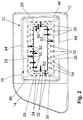
- FIG. 2 shows a schematic representation of a Lucasausströmers 10 in the direction of an air outlet opening 18.
- an aperture 12 an aperture 14, rounded portions 44 and 46 of the aperture 12 and two opposing portions 26 and 28 of the air vent 10 are shown.
- the cutouts 26 and 28 each have three rows of Openings 30, 32 and 34.
- the diameter of the openings 30, 32 and 34 decreases with increasing distance from the air outlet opening 18 to the air supply duct 22 from.
- FIG. 12 is a plan view of the air vent 10 of FIG Fig.
- the portions 26 and 28 are formed curved and the areas 44 and 46 of the diaphragm 12 have a corresponding curvature, so that the outflowing air flow is not deflected or swirled by deflecting edges thus formed and so that a deflection by the curved portions 26th and 28 continues by exploiting the Coanda effect.
- the transitions between the individual sections 26 and 28 are furthermore rounded off.
- Fig. 2 further shows how the deflection of an exiting air flow for deflection in the direction of Fig. 2 can be done down and to the left side.
- the in Fig. 2 not shown connections 40 and 42 air introduced into the chambers 36 and 38 for generating overpressure and negative pressure areas or dissipated.
- This is indicated schematically by the arrows 60, which represent outflowing air from the openings 30, 32 and 34.
- the air flows not only from the designated openings 30, 32 and 34, but from all of a chamber associated openings 30, 32 and 34. Accordingly, the air, as indicated by the arrows 62, through all openings 30, 32 and 34th the chambers 36 and 38 discharged.
- Fig. 2 From the presentation of Fig. 2 It can be seen that in addition to the use of the Coanda effect for deflecting the exiting air flow from the air outlet opening 18, the introduction of air and the discharge of air influence the air flow in the desired manner.
- the degree The deflection can also be adjusted by the amount of outflowing and discharged air.
- the two opposing portions 26 and the right portion 28 may also serve to form overpressure regions by introducing air across the apertures 30, 32, and 34, with additional formation of a left side negative pressure region in the left portion 28 a deflection of an exiting air flow to the left results.
- the four sections 26 and 28 shown can be controlled independently of each other so that both the supply and discharge of air and the amount of air supply or discharge for each chamber 36 and 38 through the second ports 40 and 42 are independently adjustable ,
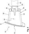
- FIG. 3 shows a schematic representation of a Lucasausströmers 10 in a side view.
- the in Fig. 3 illustrated air vent 10 is a side view of the in Fig. 1 and 2 10.
- FIG Fig. 3 schematically an air supply passage 22 is shown, which is connected to the first port 20 of the Heilausströmers 10.
- the two second connections 40 to an upper chamber 36 and a lower chamber 36 and a second connection 42 to a chamber 38 are shown.
- the second ports 40 and 42 are connected, for example, to a hose leading to a valve of another device which controls the supply and removal of air to the respective second ports 40 and 42 for generating positive and negative pressure in the chambers 36 and 38 and the regions of the sections 26 and 28 with the openings 30, 32 and 34 controls.
- FIG. 3 the chambers 36 are schematically indicated.
- the chambers 36 therefore have no straight portion as shown in FIG Fig. 3 makes the appearance, but point inside (in the housing 16) convexly curved portions 26 and 28 on.
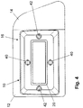
- Fig. 4 shows a schematic representation of a Lucasausströmers 10 with a view of a port 20 for an air supply channel 22.
- the rear view of a Heilausströmers 10 of Fig. 4 shows that already with reference to the Fig. 1 to 3 shown Heilausströmer 10 with respect to the first port 20 and the second ports 40 and 42nd
- Fig. 5 shows a schematic, partially sectional view of a Lucasausströmers 10 in a side view.
- the in Fig. 5 illustrated air vent 10 is a sectional view, wherein the air vent 10 is a representation of the in the Fig. 1 to 4 shown Heilausströmers 10 shows.
- Fig. 5 the convex curvature of the sections 26 is shown.
- the sections 28 have a corresponding curvature, but their curvature is in Fig. 5 not apparent.
- the areas 44 of the aperture 12, which close the air outlet opening 18 are rounded.
- an exact continuation of the convex curvature of the sections 26 and, correspondingly, a continuation of the convex curvature of the sections 44 and 46 through the areas 46 may be provided.
- Fig. 5 the openings 30, 32 and 34 of a section 28 are shown.
- the three rows shown with the openings 30, 32 and 34 extend in the direction of view Fig. 5 not along a vertical line, but are formed substantially parallel to a final edge through the aperture 12.
- Fig. 5 shows clearly that the diameters of the openings 30, 32 and 34, starting from the first port 20 to the air outlet opening 18 toward increase.
- Air is supplied to the air vent 10 via an air supply duct (not shown) (represented by arrow 48) and air is supplied and discharged separately via the second connections 40 (shown by the arrows 50) in order to divert the exiting air flow in the desired manner.
- the design of an air vents 10, as shown in the figures, has the advantage that no components for deflecting the air flow into the flow channel 24 protrude, so that it also reduces the disturbing noises which in conventional air vents due to in the Flow channel protruding components occurs, and no turbulence of the outflowing air comes.
- FIG. 5 It can also be seen that the incoming or outgoing air from the chambers 36 and in a corresponding manner from the chambers 38 via the openings 30, 32 and 34 takes place.
- Fig. 6 shows a further schematic, partially sectional view of a Lucasausströmers 10 in a side view. This side view shows in one embodiment how an airflow can be deflected downwards.
- the air vent 10 of Fig. 6 is a sectional view of the already with respect to the Fig. 1 to 5
- the lower chamber 36 via the second port 40 air is discharged (shown by arrow 56).
- About the arrows 60 and 62 is indicated how the influence of the outflowing Air flow can be made by supplying or discharging air into the chambers 36 (and 38, respectively).
- the air vent 10 shown and described in the description of the figures is suitable, noiselessly and without a multiplicity of adjustment means, which are arranged in a flow channel, an air flow due to the Coanda effect due to the curved design of the sections 26 and 28 and the generation of overpressure - And vacuum areas in the chambers 36 and 38 and the sections 26 and 28 with the openings 30, 32 and 34 to distract as desired.
Landscapes
- Engineering & Computer Science (AREA)
- Mechanical Engineering (AREA)
- Chemical & Material Sciences (AREA)
- Combustion & Propulsion (AREA)
- General Engineering & Computer Science (AREA)
- Physics & Mathematics (AREA)
- Thermal Sciences (AREA)
- Air-Flow Control Members (AREA)
- Air-Conditioning For Vehicles (AREA)
- Duct Arrangements (AREA)
Description
- Die vorliegende Erfindung betrifft einen Luftausströmer, aufweisend ein Gehäuse mit einer Luftaustrittsöffnung, einem Luftzuführkanal und einem durchgehenden Strömungskanal. Derartige Luftausströmer werden beispielsweise bei Kraftfahrzeugen zum Zuführen von Luft und zum Einstellen der Richtung der ausströmenden Luft sowie der Menge der ausströmenden Luft eingesetzt.
- Herkömmliche Luftausströmer weisen sowohl vertikal als auch horizontal verlaufende Lamellen auf, die in einem Strömungskanal angeordnet sind. Diese Lamellen können über eine Einrichtung sowohl vertikal als auch horizontal verschwenkt werden, um die Richtung der ausströmenden Luft zu beeinflussen. Derartige Luftausströmer weisen in der Regel einen rechteckigen oder runden Querschnitt auf.
- Darüber hinaus sind Luftausströmer mit einem im Wesentlichen runden Querschnitt bekannt. Diese können ebenso Lamellen aufweisen, wobei die Lamellen oftmals in einem Ring gelagert sind und die Richtung der ausströmenden Luft durch das Drehen des Rings und Verschwenken der darin gelagerten Lamellen erfolgt.
- Aus dem Stand der Technik sind ferner Luftausströmer bekannt, die Mittel aufweisen, welche eine Abrisskante für einen Luftstrom bilden.
DE 10 2010 049 110 A1 offenbart eine Luftverteilvorrichtung für ein Kraftfahrzeug. Die Luftverteilvorrichtung weist eine Luftausströmöffnung und ein Luftleitelement auf, über welches die Luftausströmrichtung eines aus dieser Luftausströmöffnung austretenden Luftstrahls veränderbar ist. Das Luftleitelement ist über Antriebelemente periodisch schwenkend bewegbar, wobei das Luftleitelement als inneres Bauteil der Luftleitvorrichtung ausgebildet ist. Die Luftleitvorrichtung weist ferner eine Prallwand auf, die einer Stauklappe im Strömungsquerschnitt des Luftkanals gegenüberliegt und in Strömungsrichtung zur Stauklappe stromaufwärts versetzt angeordnet ist. Durch einen Unterdruck, der sich im Nachlaufgebiet dieser Prallwand einstellt, wird die durch die ausgestellte Stauklappe bewirkte seitliche Ablenkung eines Luftstrahls unterstützt. -
DE 100 63 189 B4 offenbart eine Belüftungsvorrichtung mit einem in einer Richtung luftdurchströmten Kanal, der eine Luftaustrittsöffnung und innerhalb des Kanals einander paarweise gegenüberliegende, steuerbare Luftleitelemente zum Ablenken des Luftstroms aufweist. Ein erstes Luftleitelement zum Ablenken des Luftstroms ist in Richtung von der Kanalwand weg und ein zweites dem ersten Luftleitelement gegenüberliegendes Luftleitelement zum Ablenken des Luftstroms ist in Richtung zur Kanalwand hin ausgebildet. Die Luftleitelemente in der Kanalwand sind an die Kanalwand anschließend gelagert und das zweite Luftleitelement ist zum Ablenken des Luftstroms auf Grund des Coanda-Effekts ausgebildet. Hierzu ist das zweite Luftleitelement gegenüber dem ersten Luftleitelement in Kanallängsrichtung zum Kanalinneren hin versetzt angeordnet, wobei sich ein stromabwärts an der Kanalwand angeordnetes Unterdruckgebiet ausbildet. -
DE 34 37 259 C2 offenbart eine Belüftungsvorrichtung mit einer Vielzahl von nebeneinander anliegenden Lamellen, welche einen sogenannten Coanda-Effekt ausnutzen. Die Lamellen sind in einem Lüftungskanal ortsfest entlang einer fest verriegelten Kurve angeordnet und drehbar gelagert. Sie werden so angesteuert, dass jede Lamelle einen unterschiedlichen Winkel zu der anströmenden Luft einnimmt. Zur Einstellung eines großen Ausströmwinkels wird eine Hälfte der Luftdüse durch die in dieser Hälfte liegenden Lamellen so verschlossen, dass die Lamellen eine konvex gewölbte Kurve bilden. In Folge des Coanda-Effekts wird der Luftstrom entlang dieser konvexen Kurve geleitet und entsprechend abgelenkt. -
JP S54 108323 A -
US 4,989,807 A offenbart einen S-förmigen Triebwerkeingangs-Diffusor, wobei in dem Diffusor ein Umlenkblech und eine Öffnung vorgesehen sind. Über die Öffnung kann Luft abgesaugt oder zugeführt werden. - Der Nachteil bei den aus dem Stand der Technik bekannten Luftausströmern liegt in der Verwendung von Lamellen oder anderen Ablenkmitteln, welche bewegt werden müssen. Eine Bewegung von Komponenten einer Einrichtung umfasst stets das Risiko, dass es zu einem Versagen oder einer Störung auf Grund einer Beschädigung oder eines Ausfalls von Komponenten dieser Einrichtungen kommt. So könnten beispielsweise Lamellen nach häufigem Verschwenken klemmen oder das Einstellmittel, welches oftmals auf einer sogenannten Steuerlamelle gelagert ist, nur noch schwer bewegt werden.
- Vorteilhafte Weiterbildungen der Erfindung sind in den Unteransprüchen im Detail angegeben.
- Ein erfindungsgemäßer Luftausströmer weist ein Gehäuse mit einer Luftaustrittsöffnung, einen ersten Anschluss an einen Luftzuführkanal und einen durchgehenden Strömungskanal auf, wobei der Strömungskanal mindestens an zwei gegenüberliegenden Abschnitten derart gekrümmt ausgebildet ist, dass sich der Querschnitt des Strömungskanals zu der Luftaustrittsöffnung hin vergrößert und die mindestens zwei Abschnitte jeweils Öffnungen aufweisen, welche jeweils in eine hinter den Abschnitten liegende Kammer münden, wobei die Kammern jeweils einen von dem ersten Anschluss getrennten zweiten Anschluss zum Zuführen oder Abführen von Luft zur Erzeugung von Überdruck und/oder Unterdruck aufweisen, und wobei die Abschnitte mehrere Reihen von Öffnungen aufweisen.
- Bei dem erfindungsgemäßen Luftausströmer wird Frischluft oder Luft von einer Klimaanlage über den ersten Anschluss von einem Luftzuführkanal durch den Strömungskanal hindurchgeleitet. Der Strömungskanal ist so ausgebildet, dass die Luft an den gekrümmten Abschnitten entlang dieser aus der Luftaustrittsöffnung ausströmt und die durch die gekrümmte Ausbildung bewirkte Strömung auf Grund des Coanda-Effekts beibehält, so dass der Luftstrom abgelenkt wird. Um eine Einstellung der Luftausströmrichtung zu bewirken, wird in die hinter den Abschnitten gelegenen Kammern über die zweiten Anschlüsse Luft zugeführt oder Luft abgeführt, wobei sich an den Abschnitten Überdruck- und/oder Unterdruckbereiche einstellen. Diese Überdruck- und/oder Unterdruckbereiche bewirken eine Änderung der Richtung der ausströmenden Luft. So kann durch Erzeugung eines Überdrucks in beiden gegenüberliegenden Abschnitten ein im Wesentlichen geradliniger Luftstrom aus dem Luftausströmer eingestellt werden. Wird in beiden gegenüber liegenden Kammern der Abschnitte ein Unterdruck erzeuge, so wird die Luft starker abgelenkt, so dass sich ein dif so wird die Luft stärker abgelenkt, so dass sich ein diffuser Luftstrom einstellt. Wird bei zwei gegenüberliegenden Kammern in einer Kammer ein Überdruck und in der anderen Kammer ein Unterdruck erzeugt, so erfolgt eine Ablenkung des Luftstroms in Richtung des Abschnitts, in dessen Kammer der Unterdruck erzeugt wird.
- Der erfindungsgemäße Luftausströmer weist keine mechanischen Luftleitelemente im Sichtbereich auf, die eine Veränderung der Richtung der ausströmenden Luft bewirken. Dadurch ergeben sich ein optisch ansprechendes Erscheinungsbild und eine große Design-Freiheit. Darüber hinaus benötigt ein derartiger Luftausströmer weniger Bauraum als konventionelle Luftausströmer, die neben den Lamellen noch Einrichtungen zum gleichzeitigen Verschwenken einer Gruppe von Lamellen (z. B. Koppelstange) und mechanische Einstellmittel zum Verschwenken der Lamellen aufweisen. Bei der vorliegenden Erfindung wird die zum Ausströmen vorgesehene Luft über den Luftzuführschacht zugeführt. Die Änderung der Ausströmrichtung erfolgt über die zweiten Anschlüsse und eine Luftzu- bzw. Luftabfuhr aus den jeweiligen Kammern der gekrümmten Abschnitte. Zum Einstellen der Ablenkung der aus dem Luftausströmer ausströmenden Luft können Mittel vorgesehen sein, welche mechanisch, elektrisch oder anderweitig die Luftzu- und Luftabfuhr aus den Kammern zum Einstellen der Luftausströmrichtung bewirken. Jedoch ragen in den Luftzuführschacht, den durchgehenden Strömungskanal und die Luftaustrittsöffnung keine Komponenten, welche zusätzlich eine ungewünschte Verwirbelung bewirken. Die Einstellung der ausströmenden Luft erfolgt nur durch zusätzliches Einbringen von Luft durch die Öffnungen einer Kammer (Überdruck) oder durch Absaugen der ausströmenden Luft durch die Öffnungen einer Kammer (Unterdruck). Auf Grund der Ausbildung von Überdruck bzw. Unterdruck in den Kammern und der gekrümmten Ausführung der Abschnitte durch Ausnutzung des Coanda-Effekts wird eine einfache und störungsunanfällige Ausführung eines Luftausströmers bereitgestellt.
- Zur Zu- oder Abfuhr der Luft über die zweiten Anschlüsse der Kammern kann eine Einrichtung vorgesehen sein, die im Sinne eines Kompressors oder einer Pumpe Luft einbläst oder absaugt. In Abhängigkeit der Krümmung der Abschnitte sowie dem Querschnitt des Strömungskanals können verschiedene Ablenkungen der ausströmenden Luft eingestellt werden. Ferner kann Über die Einstellung des Unter- bzw. Überdrucks der Grad der Ablenkung der ausströmenden Luft maßgeblich beeinflusst werden.
- Gesteuert werden kann der Luftausströmer sowie die Zu- und Abfuhr der Luft zur Erzeugung von Überdruck und Unterdruck über ein mechanisches Einstellmittel (z. B. Joystick) oder eine Eingabe mittels eines Displays.
- Das Gehäuse des Luftausströmers kann auch vier gekrümmte Abschnitte mit Öffnungen aufweisen, wobei sich jeweils zwei Abschnitte gegenüberliegen und die vier Abschnitte im Wesentlichen einen im Querschnitt rechteckigen Strömungskanal bilden und jeder Abschnitt eine separate Kammer mit einem zweiten Anschluss zum Zuführen oder Abführen von Luft aufweist. Durch die vier gekrümmten Abschnitte kann die Luft sowohl horizontal als auch vertikal in beide Richtungen abgelenkt und zudem horizontal und vertikal abgelenkt werden. Beispielsweise können zwei aneinanderliegende Abschnitte mit einem Überdruck beaufschlagt und die anderen beiden Abschnitte mit einem Unterdruck beaufschlagt werden, so dass sich eine Ausströmungsrichtung nach unten und in eine seitliche Richtung einstellt. In Abhängigkeit der Stärke des ausgebildeten Überdrucks in den beiden Überdruck-Kammern kann eine Richtung stärker eingestellt werden als die andere. Dazu wird über die zweiten Anschlüsse dieser Kammern nicht im gleichen Maße ein Überdruck erzeugt, sondern in Abhängigsprechendes gilt für die Ausbildung des Unterdrucks über die entsprechenden Kammern der Abschnitte.
- Die Öffnungen können zu der Luftaustrittsöffnung hin einen zunehmend größeren Durchmesser aufweisen. Dadurch wird die Ablenkung der ausströmenden Luft verbessert. Beispielsweise ist eine erste Reihe direkt nach dem Luftzuführkanal angeordnet und weitere darauf folgende Reihen erstrecken sich in Richtung der Luftaustrittsöffnung, wobei der Durchmesser der Öffnungen mit jeder Reihe zu der Luftaustrittsöffnung hin zunimmt.
- Die Öffnungen können beispielsweise einen runden, eckigen, ovalen oder auch anderweitigen Querschnitt aufweisen. Ferner ist die Größe der Öffnungen in Abhängigkeit der Dimensionierung des Luftausströmers sowie des Grads der Ablenkung zu bemessen.
- Insbesondere können die Abschnitte in weiteren Ausführungsformen des Luftausströmers eine konvexe Krümmung aufweisen. Eine konvexe Krümmung stellt beispielsweise bei einem ausströmenden Luftstrom ohne die Ausbildung eines Über- oder Unterdrucks in den Kammern eine diffuse Luftzufuhr bereit.
- In weiteren Ausführungsformen weisen die Öffnungen einen im Wesentlichen runden Querschnitt auf.
- Der Strömungskanal kann auch eine gerade Anzahl von Abschnitten mit Öffnungen aufweisen, welche im Wesentlichen einen im Querschnitt runden Strömungskanal bilden, wobei jeder Abschnitt eine separate Kammer mit einem zweiten Anschluss zum Zuführen oder Abführen von Luft aufweist. Darüber hinaus ist es möglich, sämtliche Querschnittsformen für den Strömungskanal vorzusehen. Entsprechend der gewählten Querschnittsformen sind dann entsprechende Ab schnitte mit dahinterliegenden Kammern vorzusehen. Auch kann beispielsweise eine ungerade Zahl von Abschnitten und damit eine ungerade Anzahl von Kammern ausgebildet werden. Entscheidend hierbei ist, dass jede Kammer einen separaten zweiten Anschluss zum Zuführen oder Abführen von Luft aufweist.
- Der Luftausströmer kann eine die Luftaustrittsöffnung umgebende Blende aufweisen, welche in dem an der Luftaustrittsöffnung anliegenden Bereich eine den Abschnitten entsprechende Krümmung aufweist. Dadurch wird die Ablenkung der ausströmenden Luft durch die Blende nicht behindert, sondern vielmehr unterstützt.
- Weiterhin können der Strömungskanal und der Luftzufuhrkanal so ausgebildet sein, dass der Strömungskanal und der Luftzuführkanal im Bereich des ersten Anschlusses einen im Wesentlichen gleichen Querschnitt aufweisen. Dies stellt sicher, dass die ausströmende Luft nicht durch Querschnittsänderungen oder Kanten ungewollt abgelenkt oder verwirbelt wird, was das Einstellen der Richtung der ausströmenden Luft beeinträchtigen würde.
- In weiteren Ausführungsformen des Luftausströmers weist der Luftzuführkanal vor dem ersten Anschluss mindestens eine Strecke auf, die einen im Wesentlichen geradlinigen Luftstrom in den Strömungskanal bereitstellt. Diese Maßnahme dient ebenso dazu, das Ablenken der ausströmenden Luft nicht negativ zu beeinflussen.
- Die separate Zuführung von Luft in die Kammern der Abschnitte über die zweiten Anschlüsse kann über eine Steuerung einstellbar und veränderbar sein. Eine Steuerung kann beispielsweise mechanisch über eine Bedienkomponente, welche mit weiteren Mitteln zum Zu- und Abführen der Luft zu den zweiten Anschlüssen gekoppelt ist, oder elektrisch erfolgen.
- In weiteren Ausführungsformen bestehen die Abschnitte des Strömungskanals mit den Öffnungen aus einem flexiblen Material. Das flexible Material ermöglicht zusätzlich eine leichte Verformung, so dass beim Erzeugen eines Überdrucks in einer Kammer der Abschnitt um ein bestimmtes Maß weit in den Strömungskanal gedrückt wird, wodurch sich eine stärkere Krümmung und damit eine stärkere Ablenkung der ausströmenden Luft einstellt. Ferner kann über die Ausbildung der Abschnitte aus einem flexiblen Material bei Erzeugung eines Unterdrucks in einer Kammer eine Verformung dieses Abschnitts um ein bestimmtes Maß in Richtung der Kammer erfolgen, so dass hierdurch ebenso die Ablenkung der ausströmenden Luft zusätzlich beeinflusst werden kann.
- Der Luftausströmer sowie das Gehäuse des Luftausströmers können in weiteren Ausführungen aus Kunststoff bestehen. Insbesondere eignen sich hierzu Kunststoffe, welche zum Spritzgießen der Komponenten des Luftausströmers geeignet sind und entsprechend dem vorgesehenen Einsatz des Luftausströmers die erforderlichen Eigenschaften aufweisen.
- Die zweiten Anschlüsse der Kammern können rückseitig, der Luftaustrittsöffnung abgewandt, mit einer Einrichtung zum Zuführen und/oder Abführen von Luft zum Erzeugen eines Überdrucks und/oder Unterdrucks in den Kammern verbunden sein, beispielsweise ist die Einrichtung ein Kompressor oder eine Pumpe, die den Kammern Luft entzieht bzw. zuführt, wobei ferner die Einrichtung mit einem Ventil oder mehreren Ventilen gekoppelt sein kann, welche die Zu- und Abfuhr der Luft steuern. Dazu kann eine elektrische und/oder softwarebedingte Steuerung enthalten sein, die ein Öffnen und Schließen der Ventile, den Betrag des erzeugten Über- bzw. Unterdrucks und den Betrieb der Einrichtung (beispielsweise Kompressor und/oder Pumpe) steuert.
- Weiterhin kann an einer die Luftaustrittsöffnung umgebenden Blende ein Einstellmittel angeordnet sein, nach Maßgabe dessen die Richtung, die Ablenkung und/oder die Menge der ausströmenden Luft steuerbar sind. Das Einstellmittel kann mechanisch, wie vorstehend bereits angegeben, die Richtung, die Ablenkung und/oder die Menge der ausströmenden Luft steuern. Darüber hinaus kann das Einstellmittel aber auch elektrisch eine Richtungsänderung, Ablenkung und/oder Mengenregulierung der ausströmenden Luft steuern.
- Darüber hinaus kann in dem Luftzuführkanal eine Schließeinrichtung vorgesehen sein, welche dazu ausgebildet ist, die Luftzufuhr in den Strömungskanal freizugeben, zu unterbinden und die Menge der zugeführten Luft zu regulieren. Derartige Schließeinrichtungen werden beispielsweise auch als Drosselklappen bezeichnet.
- Hierbei kann die Schließeinrichtung über ein Stellmittel steuerbar sein, welches an einer die Luftaustrittsöffnung umgebenden Blende angeordnet ist. So kann die Schließeinrichtung beispielsweise mit dem Einstellmittel gekoppelt sein oder ein weiteres Mittel weist die Funktionalitäten des Einstellmittels und der Schließeinrichtung auf. Die Schließeinrichtung kann über das Stellmittel elektrisch, mechanisch oder anderweitig gesteuert werden.
- Darüber hinaus kann in dem Luftausströmer die Luftzufuhr und die Luftabfuhr in die Kammern regulierbar sein, wobei hierin die Luftzufuhr und die Luftabfuhr steuerbar ist, so dass neben dem Zu- und Abführen von Luft zur Erzeugung eines Überdrucks bzw. eines Unterdrucks auch die Stärke des Drucks bzw. Überdrucks und Unterdrucks gesteuert werden kann.
- In weiteren Ausführungsformen sind die Kammern in mindestens zwei Teilkammern unterteilt und weisen entweder jeweils einen separaten zweiten Anschluss oder mindestens ein Trennmittel auf, mittels welchem das Volumen der so gebildeten Teilkammern veränderbar ist. Dadurch kann eine noch feinere Einstellung der ausströmenden Luft erreicht werden. Alternativ können die jeweils einzelnen Abschnitte eine Vielzahl von Kammern aufweisen, die jeweils einen separaten zweiten Anschluss aufweisen oder über ein Trennmittel in ihrem Volumen veränderbar sind.
- Weitere Merkmale, Ausgestaltungsmerkmale und Weiterbildungen der Erfindung ergeben sich aus der nachfolgenden, nicht einschränkenden Figurenbeschreibung.
- Die in den Figuren gezeigten Ausführungsbeispiele weisen beispielhaften Charakter auf und sind daher nicht einschränkend zu verstehen und können bei zu implementierenden Ausführungsformen vom Veranschaulichten abweichen.
- In den Zeichnungen zeigt:
- Fig. 1
- eine schematische Darstellung eines Luftausströmers in perspektivischer Ansicht;
- Fig. 2
- eine schematische Darstellung eines Luftausströmers in Blickrichtung auf eine Luftaustrittsöffnung;
- Fig. 3
- eine schematische Darstellung eines Luftausströmers in einer Seitenansicht;
- Fig. 4
- eine schematische Darstellung eines Luftausströmers in Blickrichtung auf einen Anschluss für einen Luftzuführkanal;
- Fig. 5
- eine schematische, teilweise geschnittene Darstellung eines Luftausströmers in einer Seitenansicht; und
- Fig. 6
- eine weitere schematische, teilweise geschnittene Darstellung eines Luftausströmers in einer Seitenansicht.
- In den Figuren entsprechen mit gleichen Bezugszeichen versehene Teile in ihrer Ausgestaltung und Funktion im Wesentlichen einander.
-
Fig. 1 zeigt eine schematische Darstellung eines Luftausströmers 10 in einer perspektivischen Ansicht, wobei die Bestandteile des Luftausströmers 10 schematisch dargstellt sind. - Der Luftausströmer 10 weist ein Gehäuse 16 auf. An dem Gehäuse 16 ist an einer vorderen Luftaustrittsöffnung 18 eine Blende 12 angeordnet, wobei die Öffnung der Blende 12 im Wesentlichen der Luftaustrittsöffnung 18 des Luftausströmers 10 entspricht. An der Blende 12 ist ferner ein Blendenanschluss 14 angebracht. Vorzugsweise besteht eine die Luftaustrittsöffnung 18 umgebende Blende aus der Blende 12 und dem Blendenanschluss 14, wobei die in
Fig. 1 gezeigte Darstellung nur beispielhaft ist. So kann eine Blende sich beispielsweise über ein gesamtes Armaturenbrett bzw. das Verkleidungsteil des Armaturenbretts erstrecken und eine Blende mit mindestens einer Öffnung für einen Luftausströmer 10 bilden. - Das Gehäuse 16 des Luftausströmers 10 weist einen ersten Anschluss 20 auf, der mit einem in
Fig. 1 nicht dargestellten Luftzuführkanal 22 verbunden ist. Der erste Anschluss 20 weist einen im Wesentlichen rechteckigen Querschnitt auf und ist mit einem Strömungskanal 24 des Luftausströmers 10 verbunden. Der Strömungskanal 24 weist im Anschlussbereich an den ersten Anschluss 20 einen im Wesentlichen dem ersten Anschluss 20 entsprechenden Durchmesser auf. Der Durchmesser des Strömungskanals 24 vergrößert sich in Richtung zu der Luftaustrittsöffnung 18 hin. Der Strömungskanal 24 weist vier Abschnitte 26 und 28 auf, wobei sich jeweils zwei Abschnitte 26 und 28 gegenüberliegen und der Strömungskanal 24 von den vier Abschnitten 26 und 28 umgeben und durch die Abschnitte 26 und 28 definiert ist. - Die Abschnitte 26 und 28 weisen ferner Öffnungen 30, 32 und 34 auf. In
Fig. 1 sind jeweils nur wenige der Öffnungen 30, 32 und 34 angegeben, jedoch entsprechen die anderen, nicht bezeichneten Öffnungen den bezeichneten Öffnungen 30, 32 und 34 in den jeweiligen Reihen. - Der Abschnitt 26 weist, wie gezeigt, drei Reihen von Öffnungen 30, 32 und 34 auf, wobei sich der Durchmesser der Öffnungen 30, 32 und 34 ausgehend vom Verbindungsbereich des Strömungskanals 24 mit dem ersten Anschluss 20 zu der Luftaustrittsöffnung 18 hin vergrößert.
- Jeder der Abschnitte 26 und 28 weist eine dahinterliegende Kammer 36 und 38 auf. Über die Öffnungen 30, 32 und 34 besteht eine Verbindung zwischen den Kammern 36, 38 und dem Strömungskanal 24. Die Kammern 36 und 38 weisen jeweils einen zweiten Anschluss 40 und 42 auf. Die beiden gegenüberliegenden Kammern 36 der Abschnitte 26 (in
Fig. 1 ist nur der untere Abschnitt 26 dargestellt) weisen jeweils einen separaten zweiten Anschluss 40 auf und die Kammern 38 der Abschnitte 28 weisen jeweils einen zweiten Anschluss 42 auf. Über die zweiten Anschlüsse 40 und 42 kann zur Erzeugung eines Überdrucks oder eines Unterdrucks in den entsprechenden Kammern 36 und 38 sowie in den Bereichen der Abschnitte 26 und 28 mit den Öffnungen 30, 32 und 34 Luft zu- bzw. abgeführt werden. - Die Abschnitte 26 und 28 sind gekrümmt ausgebildet und weisen eine konvexe Krümmung auf, wobei sich mit zunehmendem Abstand zu dem ersten Anschluss 20 der Querschnitt des Strömungskanals 24 vergrößert. Dementsprechend sind auch die Öffnungen 30, 32 und 34 so ausgebildet, dass sich deren Durchmesser in Abhängigkeit des sich vergrößernden Querschnitts des Strömungskanals 24 vergrößert. Die konvexe Krümmung der Abschnitte 26 und 28 bewirkt, dass von dem Luftzuführkanal 22 zugeführte Luft auf Grund des sogenannten Coanda-Effekts entlang der Oberfläche der Abschnitte 26 und 28 strömt und somit in einem bestimmten Maß abgelenkt wird. Um die Ablenkung der ausströmenden Luft in gewünschter Weise zu beeinflussen, wird den zweiten Anschlüssen 40 und 42 Luft zu- oder abgeführt, so dass beispielsweise Luft aus dem unteren Abschnitt 26 aus den Öffnungen 30, 32 und 34 strömt und damit eine Ablenkung des austretenden Luftstroms nach oben in Richtung des gegenüberliegenden Abschnitts 26 bewirkt.
- Die über die zweiten Anschlüsse 40 und 42 zugeführte bzw. abgeführte Luft wird über eine weitere Einrichtung eingestellt. Der Luftstrom, welcher über den Luftzuführkanal 22 dem Luftausströmer 10 zugeführt wird, beeinflusst nicht die den Kammern 36 und 38 zugeführte Luft bzw. abgeführte Luft über die Anschlüsse 40 und 42. Es gibt daher einen Luftstrom über den Luftzuführkanal 22, wie bereits von Lamellenströmen aus dem Stand der Technik bekannt, und zusätzlich einen sogenannten Steuerungsluftstrom, welcher beispielsweise von einem Kompressor über ein Ventil oder Schaltmittel gezielt den Anschlüssen 40 und 42 zugeführt wird.
- Zusätzlich kann über den Kompressor oder eine weitere Einrichtung auch Luft über die Kammern 36 und 38 abgeführt werden. Über die Öffnungen 30, 32 und 34 wird demnach Luft des ausströmenden Luftstroms durch Ausbildung von Unterdruckbereichen in den entsprechenden Kammern 36 und 38 und den Bereichen der Abschnitte 26 und 28 mit den Öffnungen 30, 32 und 34 entzogen.
- Zur Steuerung des ausströmenden Luftstroms kann an dem Blendenanschluss 14 ein nicht dargestelltes Steuerungsteil vorgesehen sein, welches mechanisch die Zu- oder Abfuhr von Luft in die Kammern 36 und 38 oder aus den Kammern 36 und 38 bewirkt. Die Steuerung kann aber auch elektrisch erfolgen, so dass eine Betätigung des Steuermittels eine entsprechende Aktion durch eine Einrichtung zum Zu- und Abführen der Luft regelt. Eine derartige Einrichtung kann aber auch über ein Display eines Kraftfahrzeugs gesteuert werden, worüber sämtliche Einstellungen, beispielsweise auch die einer Klimaanlage, eingestellt werden können.
- Der in
Fig. 1 dargestellte Luftausströmer 10 bewirkt durch die gezielte Abfuhr von Luft über die zweiten Anschlüsse 40 und 42 aus den Kammern 36 und 38 eine Steuerung des ausströmenden Luftstromes. Zusätzlich kann der Luftzuführkanal 22 eine Drosselklappe oder andere Schließeinrichtungen aufweisen, die ebenso, wie vorstehend beschrieben, gesteuert werden und die Menge der ausströmenden Luft aus dem Luftausströmer 10 einstellen und auch vollständig unterbinden können. Zusätzlich kann über weitere Mittel und Einrichtungen auch die Menge der zu- oder abgeführten Luft aus den Kammern 36 und 38 gesteuert werden, so dass sich darüber auch der Grad der Ablenkung steuern lässt. -
Fig. 2 zeigt eine schematische Darstellung eines Luftausströmers 10 in Blickrichtung auf eine Luftaustrittsöffnung 18. In dieser Darstellung sind eine Blende 12, ein Blendenanschluss 14, abgerundete Bereiche 44 und 46 der Blende 12 sowie jeweils zwei sich gegenüberliegende Abschnitte 26 und 28 des Luftausströmers 10 dargestellt. Die Ausschnitte 26 und 28 weisen jeweils drei Reihen von Öffnungen 30, 32 und 34 auf. Der Durchmesser der Öffnungen 30, 32 und 34 nimmt mit zunehmendem Abstand von der Luftaustrittsöffnung 18 zu dem Luftzuführkanal 22 hin ab. Der Luftausströmer 10 vonFig. 2 stellt eine Draufsicht auf den Luftausströmer 10 vonFig. 1 dar. Daher sind die Abschnitte 26 und 28 gekrümmt ausgebildet und die Bereiche 44 und 46 der Blende 12 weisen eine entsprechende Krümmung auf, so dass der ausströmende Luftstrom nicht durch so gebildete Ablenkkanten umgelenkt oder verwirbelt wird und so dass eine Ablenkung durch die gekrümmten Abschnitte 26 und 28 durch Ausnutzung des Coanda-Effekts fortgeführt wird. - Um Verwirbelungen des Luftstroms zu vermeiden sind ferner die Übergänge zwischen den einzelnen Abschnitten 26 und 28 abgerundet ausgebildet.
-
Fig. 2 zeigt ferner, wie die Ablenkung eines austretenden Luftstroms zur Ablenkung in Blickrichtung aufFig. 2 nach unten und auf die linke Seite erfolgen kann. Hierzu wird über die inFig. 2 nicht dargestellten Anschlüsse 40 und 42 Luft in die Kammern 36 und 38 zur Erzeugung von Überdruck und Unterdruckbereichen eingebracht bzw. abgeführt. Dies wird schematisch durch die Pfeile 60 angedeutet, welche ausströmende Luft aus den Öffnungen 30, 32 und 34 darstellen. Selbstverständlich strömt die Luft nicht nur aus den bezeichneten Öffnungen 30, 32 und 34, sondern aus allen einer Kammer zugeordneten Öffnungen 30, 32 und 34. Entsprechend wird die Luft, wie durch die Pfeile 62 angedeutet, auch durch alle Öffnungen 30, 32 und 34 der Kammern 36 und 38 abgeführt. - Aus der Darstellung von
Fig. 2 ist ersichtlich, dass neben der Ausnutzung des Coanda-Effekts zur Ablenkung des austretenden Luftstroms aus der Luftaustrittsöffnung 18 das Einbringen von Luft und das Abführen von Luft den Luftstrom in der gewünschten Weise beeinflussen. Der Grad der Ablenkung kann ferner durch den Betrag der ausströmenden und abgeführten Luft eingestellt werden. Anders als inFig. 2 dargestellt, können aber auch beispielsweise die beiden gegenüberliegenden Bereiche 26 und der rechte Abschnitt 28 zum Ausbilden von Überdruckbereichen durch Einbringen von Luft über die Öffnungen 30, 32 und 34 dienen, wobei sich durch zusätzliches Ausbilden eines Unterdruckbereichs auf der linken Seite in dem linken Abschnitt 28 eine Ablenkung eines austretenden Luftstrom nach links ergibt. Die vier gezeigten Abschnitte 26 und 28 können unabhängig voneinander gesteuert werden, so dass sowohl das Zu- oder Abführen von Luft sowie die Stärke des Zu- oder Abführens von Luft für jede Kammer 36 und 38 durch die zweiten Anschlüsse 40 und 42 unabhängig voneinander einstellbar ist. -
Fig. 3 zeigt eine schematische Darstellung eines Luftausströmers 10 in einer Seitenansicht. Der inFig. 3 dargestellte Luftausströmer 10 ist eine Seitenansicht des inFig. 1 und2 gezeigten Luftausströmers 10. InFig. 3 ist schematisch ein Luftzuführkanal 22 dargestellt, der mit dem ersten Anschluss 20 des Luftausströmers 10 verbunden ist. Es sind ferner die beiden zweiten Anschlüsse 40 zu einer oberen Kammer 36 und einer unteren Kammer 36 sowie ein zweiter Anschluss 42 zu einer Kammer 38 dargestellt. Die zweiten Anschlüsse 40 und 42 sind beispielsweise mit einem Schlauch verbunden, der zu einem Ventil einer weiteren Einrichtung führt, die das Zu- und Abführen von Luft zu den jeweiligen zweiten Anschlüssen 40 und 42 zur Erzeugung von Über- und Unterdruck in den Kammern 36 und 38 und den Bereichen der Abschnitte 26 und 28 mit den Öffnungen 30, 32 und 34 steuert. - In
Fig. 3 sind die Kammern 36 schematisch angedeutet. Die Kammern 36 weisen daher keinen geraden Abschnitt auf, wie es inFig. 3 den Anschein macht, sondern weisen innenliegend (in dem Gehäuse 16) konvex gekrümmte Abschnitte 26 und 28 auf. -
Fig. 4 zeigt eine schematische Darstellung eines Luftausströmers 10 mit Blick auf einen Anschluss 20 für einen Luftzuführkanal 22. Die Rückansicht eines Luftausströmers 10 vonFig. 4 zeigt den bereits mit Bezug auf dieFig. 1 bis 3 gezeigten Luftausströmer 10 mit Blick auf den ersten Anschluss 20 und die zweiten Anschlüsse 40 und 42. -
Fig. 5 zeigt eine schematische, teilweise geschnittene Darstellung eines Luftausströmers 10 in einer Seitenansicht. Der inFig. 5 dargestellte Luftausströmer 10 zeigt eine Schnittansicht, wobei der Luftausströmer 10 eine Darstellung des in denFig. 1 bis 4 gezeigten Luftausströmers 10 zeigt. - In
Fig. 5 ist die konvexe Krümmung der Abschnitte 26 gezeigt. Die Abschnitte 28 weisen eine entsprechende Krümmung auf, jedoch ist deren Krümmung inFig. 5 nicht ersichtlich. Die Bereiche 44 der Blende 12, die die Luftaustrittsöffnung 18 abschließen, sind abgerundet. Anders als inFig. 5 dargestellt, kann jedoch eine exakte Fortführung der konvexen Krümmung der Abschnitte 26 und entsprechend eine Fortführung der konvexen Krümmung der Abschnitte 44 und 46 durch die Bereiche 46 bereitgestellt sein. - In
Fig. 5 sind die Öffnungen 30, 32 und 34 eines Abschnitts 28 dargestellt. Die drei gezeigten Reihen mit den Öffnungen 30, 32 und 34 verlaufen in Blickrichtung aufFig. 5 nicht entlang einer vertikalen Linie, sondern sind im Wesentlichen parallel zu einer abschließenden Kante durch die Blende 12 ausgebildet.Fig. 5 zeigt hierbei deutlich, dass die Durchmesser der Öffnungen 30, 32 und 34 ausgehend von dem ersten Anschluss 20 zu der Luftaustrittsöffnung 18 hin zunehmen. - Dem Luftausströmer 10 wird über einen nicht dargestellten Luftzuführkanal 22 Luft zugeführt (dargestellt durch Pfeil 48) und über die zweiten Anschlüsse 40 wird gesondert Luft zu- und abgeführt (dargestellt durch die Pfeile 50), um den austretenden Luftstrom in der gewünschten Weise abzulenken.
- Die Ausgestaltung eines Luftausströmers 10, wie in den Figuren gezeigt, weist den Vorteil auf, dass keine Komponenten zum Ablenken des Luftstroms in den Strömungskanal 24 ragen, so dass es auch zu einer Reduzierung von störenden Geräuschen, welche bei konventionellen Luftausströmern auf Grund der in den Strömungskanal ragenden Komponenten auftritt, und zu keinen Verwirbelungen der ausströmenden Luft kommt.
- Durch
Fig. 5 ist ferner ersichtlich, dass die zu- oder abgeführte Luft aus den Kammern 36 und in entsprechender Weise aus den Kammern 38 über die Öffnungen 30, 32 und 34 erfolgt. -
Fig. 6 zeigt eine weitere schematische, teilweise geschnittene Darstellung eines Luftausströmers 10 in einer Seitenansicht. Diese Seitenansicht zeigt in einer Ausführung, wie ein Luftstrom nach unten abgelenkt werden kann. Der Luftausströmer 10 vonFig. 6 ist eine Schnittansicht der bereits mit Bezug auf dieFig. 1 bis 5 beschriebenen und gezeigten Luftausströmer 10. Um den Luftstrom (dargestellt durch Pfeil 48) aus der Luftaustrittsöffnung 18 nach unten abzulenken (dargestellt durch Pfeil 52) wird in die obere Kammer 36 über den zweiten Anschluss 40 Luft zugeführt (dargestellt durch Pfeil 54). - Dazu wird der unteren Kammer 36 über den zweiten Anschluss 40 Luft abgeführt (dargestellt durch Pfeil 56). Hierbei kommt es zu einem Überdruckbereich in der oberen Kammer 36 sowie dem Abschnitt 26 mit den Öffnungen 30, 32 und 34 und zu einem Unterdruckbereich in der unteren Kammer 36 sowie dem Abschnitt 26 mit den Öffnungen 30, 32 und 34. Über die Pfeile 60 und 62 ist angedeutet, wie die Beeinflussung des ausströmenden Luftstroms durch Zuführen oder Abführen von Luft in die Kammern 36 (und entsprechend 38) erfolgen kann.
- Der in der Figurenbeschreibung gezeigte und beschriebene Luftausströmer 10 eignet sich dazu, geräuschlos und ohne eine Vielzahl von Einstellmitteln, welche in einem Strömungskanal angeordnet sind, einen Luftstrom auf Grund des Coanda-Effekts durch die gekrümmte Ausführung der Abschnitte 26 und 28 und der Erzeugung von Überdruck- und Unterdruckbereichen in den Kammern 36 und 38 sowie den Abschnitten 26 und 28 mit den Öffnungen 30, 32 und 34 beliebig abzulenken.
-
- 10
- Luftausströmer
- 12
- Blende
- 14
- Blendenanschluss
- 16
- Gehäuse
- 18
- Luftaustrittsöffnung
- 20
- erster Anschluss
- 22
- Luftzuführkanal
- 24
- Strömungskanal
- 26
- Abschnitt
- 28
- Abschnitt
- 30
- Öffnung
- 32
- Öffnung
- 34
- Öffnung
- 36
- Kammer
- 38
- Kammer
- 40
- zweiter Anschluss
- 42
- zweiter Anschluss
- 44
- Bereich
- 46
- Bereich
- 48
- Pfeil
- 50
- Pfeil
- 52
- Pfeil
- 54
- Pfeil
- 56
- Pfeil
- 60
- Pfeil
- 62
- Pfeil
Claims (18)
- Luftausströmer (10), aufweisend ein Gehäuse (16) mit einer Luftaustrittsöffnung (18), einen ersten Anschluss (20) an einem Luftzuführkanal (22) und einen durchgehenden Strömungskanal (24), wobei der Strömungskanal (24) mindestens an zwei gegenüberliegenden Abschnitten (26; 28) derart gekrümmt ausgebildet ist, dass sich der Querschnitt des Strömungskanals (24) zu der Luftaustrittsöffnung (18) hin vergrößert, und die mindestens zwei Abschnitte (26; 28) jeweils Öffnungen (30, 32, 34) aufweisen, welche jeweils in eine hinter den Abschnitten (26; 28) liegende Kammer (36; 38) münden, wobei die Kammern (36; 38) jeweils einen von dem ersten Anschluss (20) getrennten zweiten Anschluss (40; 42) zum Zuführen oder Abführen von Luft zur Erzeugung von Überdruck und/oder Unterdruck aufweisen, und wobei die Abschnitte (26, 28) mehrere Reihen von Öffnungen (30, 32, 34) aufweisen.
- Luftausströmer (10) nach Anspruch 1, wobei das Gehäuse (16) vier gekrümmte Abschnitte (26, 28) mit Öffnungen (30, 32, 34) aufweist, wobei sich jeweils zwei Abschnitte (26; 28) gegenüberliegen und die vier Abschnitte (26, 28) einen im Querschnitt rechteckigen Strömungskanal (24) bilden und jeder Abschnitt (26, 28) eine separate Kammer (36, 38) mit einem zweiten Anschluss (40, 42) zum Zuführen oder Abführen von Luft aufweist.
- Luftausströmer (10) nach Anspruch 1 oder 2, wobei die Öffnungen (30, 32, 34) zu der Luftaustrittsöffnung (18) hin einen zunehmend größeren Durchmesser aufweisen.
- Luftausströmer (10) nach einem der Ansprüche 1 bis 3, wobei die Abschnitte (26, 28) eine konvexe Krümmung aufweisen.
- Luftausströmer (10) nach einem der Ansprüche 1 bis 4, wobei die Öffnungen (30, 32, 34) einen runden Querschnitt aufweisen.
- Luftausströmer (10) nach einem der Ansprüche 1 oder 3 bis 5, wobei der Strömungskanal (24) eine gerade Anzahl von Abschnitten mit Öffnungen (30, 32, 34) aufweist, welche einen im Querschnitt runden Strömungskanal bilden, wobei jeder Abschnitt eine separate Kammer mit einem zweiten Anschluss zum Zuführen oder Abführen von Luft aufweist.
- Luftausströmer (10) nach einem der Ansprüche 1 bis 6, aufweisend eine die Luftaustrittsöffnung (18) umgebende Blende (12), welche in den an der Luftaustrittsöffnung (18) anliegenden Bereichen (44, 46) eine den Abschnitten (26, 28) entsprechende Krümmung aufweist.
- Luftausströmer (10) nach einem der Ansprüche 1 bis 7, wobei der Strömungskanal (24) und der Luftzuführkanal (22) im Bereich des ersten Anschlusses (20) einen gleichen Querschnitt aufweisen.
- Luftausströmer (10) nach einem der Ansprüche 1 bis 8, wobei der Luftzuführkanal (22) vor dem ersten Anschluss (20) mindestens eine Strecke aufweist, die einen geradlinigen Luftstrom in den Strömungskanal (24) bereitstellt.
- Luftausströmer (10) nach einem der Ansprüche 1 bis 9, wobei die separate Zuführung von Luft in die Kammern (36, 38) der Abschnitte (26, 28) über die zweiten Anschlüsse (40, 42) über eine Steuerung einstellbar und veränderbar ist.
- Luftausströmer (10) nach einem der Ansprüche 1 bis 10, wobei die Abschnitte (26, 28) des Strömungskanals (24) mit den Öffnungen (30, 32, 34) aus einem flexiblen Material bestehen.
- Luftausströmer (10) nach einem der Ansprüche 1 bis 11, wobei der Luftausströmer (10) aus Kunststoff besteht.
- Luftausströmer (10) nach einem der Ansprüche 1 bis 12, wobei die zweiten Anschlüsse (40, 42) der Kammern (36, 38) rückseitig, der Luftaustrittsöffnung (18) abgewandt, mit einer Einrichtung zum Zuführen und/oder Abführen von Luft zum Erzeugen eines Überdrucks und/oder eines Unterdrucks in den Kammern (36, 38) verbindbar sind.
- Luftausströmer (10) nach einem der Ansprüche 1 bis 13, wobei an einer die Luftaustrittsöffnung (18) umgebenden Blende (12) ein Einstellmittel angeordnet ist, nach Maßgabe dessen die Richtung, die Ablenkung und/oder die Menge der ausströmenden Luft steuerbar ist.
- Luftausströmer (10) nach einem der Ansprüche 1 bis 14, wobei in dem Luftzuführkanal (22) eine Schließeinrichtung vorgesehen ist, welche dazu ausgebildet ist, die Luftzufuhr in den Strömungskanal (24) freizugeben, zu unterbinden und die Menge der zugeführten Luft zu regulieren.
- Luftausströmer (10) nach Anspruch 15, wobei die Schließeinrichtung über ein Stellmittel steuerbar ist, welches an einer die Luftaustrittsöffnung (18) umgebenden Blende (12) angeordnet ist.
- Luftausströmer (10) nach einem der Ansprüche 1 bis 16, wobei die Luftzufuhr und die Luftabfuhr in die Kammern (36, 38) regulierbar ist.
- Luftausströmer (10) nach einem der Ansprüche 1 bis 17, wobei die Kammern (36, 38) in mindestens zwei Teilkammern unterteilt sind und entweder jeweils einen separaten zweiten Anschluss aufweisen oder mindestens ein Trennmittel aufweisen, mittels welchem das Volumen der so gebildeten Teilkammern veränderbar ist.
Applications Claiming Priority (2)
| Application Number | Priority Date | Filing Date | Title |
|---|---|---|---|
| DE201310111175 DE102013111175B3 (de) | 2013-10-09 | 2013-10-09 | Luftausströmer |
| PCT/EP2014/070537 WO2015052012A1 (de) | 2013-10-09 | 2014-09-25 | Luftausströmer |
Publications (2)
| Publication Number | Publication Date |
|---|---|
| EP3055624A1 EP3055624A1 (de) | 2016-08-17 |
| EP3055624B1 true EP3055624B1 (de) | 2018-11-21 |
Family
ID=51353200
Family Applications (1)
| Application Number | Title | Priority Date | Filing Date |
|---|---|---|---|
| EP14777061.4A Not-in-force EP3055624B1 (de) | 2013-10-09 | 2014-09-25 | Luftausströmer |
Country Status (7)
| Country | Link |
|---|---|
| US (1) | US20160236541A1 (de) |
| EP (1) | EP3055624B1 (de) |
| JP (1) | JP6440700B2 (de) |
| KR (1) | KR20160067952A (de) |
| CN (1) | CN105683673B (de) |
| DE (1) | DE102013111175B3 (de) |
| WO (1) | WO2015052012A1 (de) |
Families Citing this family (20)
| Publication number | Priority date | Publication date | Assignee | Title |
|---|---|---|---|---|
| FR3031474B1 (fr) * | 2015-01-12 | 2017-04-21 | Peugeot Citroen Automobiles Sa | Dispositif de diffusion de fluide a partie principale divergente et moyens d’action sur le fluide, pour une extremite de conduit |
| US9557070B2 (en) | 2015-05-07 | 2017-01-31 | Samsung Electronics Co., Ltd. | Air conditioner and method for controlling the same |
| KR101707618B1 (ko) * | 2015-05-07 | 2017-02-21 | 삼성전자주식회사 | 공기 조화기 및 그 제어 방법 |
| DE102015210258B4 (de) | 2015-06-03 | 2022-08-25 | Bayerische Motoren Werke Aktiengesellschaft | Luftausströmer und Verfahren zum Einleiten von Luft in einen Raum |
| DE102015109068A1 (de) * | 2015-06-09 | 2016-12-15 | Dr. Ing. H.C. F. Porsche Aktiengesellschaft | Personenanströmer für ein Fahrzeug |
| DE102015116242B3 (de) * | 2015-09-25 | 2016-09-22 | Dr. Schneider Kunststoffwerke Gmbh | Luftausströmer |
| CN108291728B (zh) * | 2015-12-02 | 2021-07-13 | 豪威株式会社 | 空气净化器 |
| DE102016110933B3 (de) * | 2016-06-15 | 2017-05-18 | Dr. Schneider Kunststoffwerke Gmbh | Luftausströmer |
| CN106352515B (zh) * | 2016-08-12 | 2021-11-05 | 珠海格力电器股份有限公司 | 空调器 |
| JP2018203088A (ja) * | 2017-06-06 | 2018-12-27 | 豊和化成株式会社 | レジスタ |
| JP7068799B2 (ja) * | 2017-10-26 | 2022-05-17 | ダイキョーニシカワ株式会社 | 車両用送風装置 |
| DE102018100939B4 (de) * | 2018-01-17 | 2026-03-26 | Dr. Ing. H.C. F. Porsche Aktiengesellschaft | Verfahren zum Betrieb eines Lufteinströmers |
| DE102018203076A1 (de) * | 2018-03-01 | 2019-09-05 | Volkswagen Aktiengesellschaft | Lüftungsvorrichtung und Kraftfahrzeug |
| JP7255169B2 (ja) | 2018-04-11 | 2023-04-11 | 株式会社デンソー | 空気吹出装置 |
| US11014432B2 (en) * | 2018-08-03 | 2021-05-25 | Ford Global Technologies, Llc | Vehicle vent assembly |
| MY200063A (en) * | 2019-04-02 | 2023-12-06 | Daikin Res & Development Malaysia Sdn Bhd | A fluid discharge conduit assembly |
| CN111043694B (zh) * | 2020-01-16 | 2021-06-25 | 山东耘威医疗科技有限公司 | 生物实验室空气处理系统 |
| JP2023097028A (ja) * | 2021-12-27 | 2023-07-07 | 株式会社クボタ | 作業機 |
| KR102793275B1 (ko) * | 2022-12-01 | 2025-04-08 | 장준수 | 환기 시스템 |
| FR3148169B1 (fr) * | 2023-04-25 | 2026-05-01 | Psa Automobiles Sa | Boîtier de dispositif d’aération pour véhicule automobile. |
Family Cites Families (42)
| Publication number | Priority date | Publication date | Assignee | Title |
|---|---|---|---|---|
| US3423026A (en) * | 1967-10-30 | 1969-01-21 | Gen Motors Corp | Windshield cleaning device utilizing an oscillatory fluid stream |
| US3745906A (en) * | 1971-06-28 | 1973-07-17 | Nissan Motor | Defroster |
| US3922959A (en) * | 1973-12-20 | 1975-12-02 | Tech Adviesbureau Treffers B V | Air outlet casing |
| US4266722A (en) * | 1977-08-10 | 1981-05-12 | Matsushita Electric Industrial Co., Ltd. | Fluid deflecting assembly |
| US4326452A (en) * | 1977-10-24 | 1982-04-27 | Matsushita Electric Industrial Co., Ltd. | Fluid diverting assembly |
| JPS54108323A (en) * | 1978-02-13 | 1979-08-24 | Matsushita Electric Ind Co Ltd | Air blow-off device for vehicles |
| JPS5417650U (de) * | 1978-07-17 | 1979-02-05 | ||
| JPS6078824A (ja) * | 1983-10-07 | 1985-05-04 | Nippon Denso Co Ltd | 空気調和装置の流体吹出口 |
| AU565295B2 (en) * | 1983-10-13 | 1987-09-10 | Matsushita Electric Industrial Co., Ltd. | Fluid deflecting assembly |
| JPS60180947U (ja) * | 1984-05-11 | 1985-11-30 | 小島プレス工業株式会社 | レジスタの風向切換装置 |
| JPS60180808U (ja) * | 1984-05-14 | 1985-11-30 | 小島プレス工業株式会社 | 流体素子の風向偏向装置 |
| JPS60182641U (ja) * | 1984-05-15 | 1985-12-04 | 小島プレス工業株式会社 | レジスタ |
| US4686890A (en) * | 1984-09-14 | 1987-08-18 | Bowles Fluidics Corporation | Air distribution system |
| KR920007809B1 (ko) * | 1984-10-11 | 1992-09-17 | 가부시기가이샤 히다찌 세이사꾸쇼 | 클린 룸 |
| US4644854A (en) * | 1985-03-27 | 1987-02-24 | Bowles Fluidics Corporation | Air sweep defroster |
| US4709622A (en) * | 1986-04-07 | 1987-12-01 | Bowles Fluidics Corporation | Fluidic oscillator |
| DE8713694U1 (de) * | 1987-10-13 | 1989-02-09 | Heinrich Nickel Gmbh, 5240 Betzdorf | Quell-Luftauslaß für Lüftungs- und Klimatisierungszwecke |
| US4989807A (en) * | 1988-04-07 | 1991-02-05 | Grumman Aerospace Corporation | S-shaped jet engine inlet diffuser |
| US5263667A (en) * | 1991-09-09 | 1993-11-23 | The Boeing Company | Perforated wing panel with variable porosity |
| US6729564B2 (en) * | 2000-07-21 | 2004-05-04 | Bowles Fluidics Corporation | Fluidic SPA Nozzles with dual operating modes and methods |
| DE10063189B4 (de) * | 2000-12-19 | 2007-04-12 | Daimlerchrysler Ag | Belüftungsvorrichtung |
| ITTO20010223A1 (it) * | 2001-03-12 | 2002-09-12 | Fiat Ricerche | Sistema di distribuzione di aria. |
| US6390116B1 (en) * | 2001-07-16 | 2002-05-21 | Illinois Institute Of Technology | Large amplitude pneumatic oscillator |
| DE60207168T2 (de) * | 2001-09-07 | 2006-08-10 | Nihon Plast Co., Ltd., Fuji | Lüftungsanlage |
| US6780098B2 (en) * | 2002-02-15 | 2004-08-24 | Nifco Inc. | Regulator for air outlet |
| CA2661810C (en) * | 2002-04-18 | 2011-05-31 | Airbus Deutschland Gmbh | Perforated skin structure for laminar-flow systems |
| JP3879655B2 (ja) * | 2002-11-06 | 2007-02-14 | 株式会社デンソー | 車両空調用天井吹出装置 |
| JP3971991B2 (ja) * | 2002-12-03 | 2007-09-05 | 株式会社日立産機システム | エアシャワ装置 |
| US6902474B2 (en) * | 2003-01-31 | 2005-06-07 | Collins & Aikman Products Co. | Air duct outlet with single vane air stream direction control |
| ITTO20031007A1 (it) * | 2003-12-16 | 2005-06-17 | Fiat Ricerche | Sistema per la distribuzione di aria ad una fila di posti in un compartimento passeggeri di un mezzo di trasporto o in un ambiente di edificio. |
| JP4506758B2 (ja) * | 2006-05-23 | 2010-07-21 | トヨタ自動車株式会社 | 空調装置の吹出口構造 |
| JP4670749B2 (ja) * | 2006-06-20 | 2011-04-13 | トヨタ自動車株式会社 | 空調装置の吹出口構造 |
| ATE479567T1 (de) * | 2008-05-06 | 2010-09-15 | Fiat Ricerche | Luftdiffusor oder verteilungsvorrichtung mit synthetischen düsen |
| US7839637B2 (en) * | 2008-09-24 | 2010-11-23 | Cisco Technology, Inc. | Air-cooling of electronics cards |
| DE102008052792B4 (de) * | 2008-10-22 | 2010-11-04 | Airbus Deutschland Gmbh | Luftführungselement und Luftführungselementanordnung für eine Flugzeugklimaanlage |
| DE102010049110A1 (de) * | 2010-10-21 | 2011-06-09 | Daimler Ag | Luftverteilvorrichtung für ein Kraftfahrzeug |
| CN102478927B (zh) * | 2010-11-25 | 2016-09-28 | 鸿富锦精密工业(深圳)有限公司 | 服务器机柜 |
| DE102011076456A1 (de) * | 2011-05-25 | 2012-11-29 | Siemens Aktiengesellschaft | Vorrichtung zum Mischen eines ersten und eines zweiten Medienstroms eines Strömungsmediums |
| US20140113536A1 (en) * | 2012-10-23 | 2014-04-24 | Visteon Global Technologies, Inc. | Zonal airflow system for a vehicle |
| EP2983829B1 (de) * | 2013-04-03 | 2021-07-21 | dlhBowles Inc. | Fluidikvorrichtung für oszillierenden luftstrom für oberflächenreinigung |
| DE102013210053B3 (de) * | 2013-05-29 | 2014-09-11 | Faurecia Innenraum Systeme Gmbh | Luftausströmer |
| US9950592B2 (en) * | 2014-08-20 | 2018-04-24 | Ford Global Technologies, Llc | Line register |
-
2013
- 2013-10-09 DE DE201310111175 patent/DE102013111175B3/de active Active
-
2014
- 2014-09-25 US US15/028,710 patent/US20160236541A1/en not_active Abandoned
- 2014-09-25 EP EP14777061.4A patent/EP3055624B1/de not_active Not-in-force
- 2014-09-25 KR KR1020167012028A patent/KR20160067952A/ko not_active Ceased
- 2014-09-25 WO PCT/EP2014/070537 patent/WO2015052012A1/de not_active Ceased
- 2014-09-25 CN CN201480055514.5A patent/CN105683673B/zh active Active
- 2014-09-25 JP JP2016521586A patent/JP6440700B2/ja not_active Expired - Fee Related
Non-Patent Citations (1)
| Title |
|---|
| None * |
Also Published As
| Publication number | Publication date |
|---|---|
| JP6440700B2 (ja) | 2018-12-19 |
| WO2015052012A1 (de) | 2015-04-16 |
| CN105683673A (zh) | 2016-06-15 |
| CN105683673B (zh) | 2018-11-23 |
| EP3055624A1 (de) | 2016-08-17 |
| KR20160067952A (ko) | 2016-06-14 |
| DE102013111175B3 (de) | 2014-09-04 |
| JP2016533296A (ja) | 2016-10-27 |
| US20160236541A1 (en) | 2016-08-18 |
Similar Documents
| Publication | Publication Date | Title |
|---|---|---|
| DE102013111175B3 (de) | Luftausströmer | |
| EP3403859B1 (de) | Luftausströmer | |
| EP3063026B1 (de) | Luftdüse | |
| EP3192684B1 (de) | Einrichtung zum verstellen von lamellen eines luftausströmers | |
| DE102017120417A1 (de) | Luftausströmer mit einstellbarer Luftaustrittsrichtung, insbesondere Flach- oder Fugenausströmer | |
| DE19943822B4 (de) | Strömungsleitanordnung, insbesondere Ausströmgrill für Lüftungs- und Klimaanlagen von Kraftfahrzeugen | |
| WO2017050754A1 (de) | Luftausströmer | |
| DE102009007037A1 (de) | Ausströmdüse einer Belüftungsvorrichtung oder Klimaanlage für Fahrzeuge | |
| DE102018122999A1 (de) | Luftausströmer | |
| EP3941766B1 (de) | Belüftungsanordnung zur belüftung eines kraftfahrzeuginnenraums | |
| EP3321113B1 (de) | Luftausströmer | |
| DE102020131095A1 (de) | Lüftungseinrichtung | |
| EP1243450B1 (de) | Strömungsauslassvorrichtung, insbesondere für ein Fahrzeuginnenraum-Belüftungssystem | |
| DE102019209011A1 (de) | Lustausströmer | |
| DE102016013353A1 (de) | Ausströmer für ein Kraftfahrzeug und zugehöriges Kraftfahrzeug | |
| DE102015210258B4 (de) | Luftausströmer und Verfahren zum Einleiten von Luft in einen Raum | |
| EP0368017B1 (de) | Luftausströmorgan für den Innenraum von Kraftfahrzeugen | |
| DE102008016238A1 (de) | Lüftdüse | |
| DE10209074A1 (de) | Belüftungseinrichtung | |
| DE102015101970B4 (de) | Belüftungseinrichtung für ein Fahrzeugarmaturenbrett | |
| DE102023111195B3 (de) | Fahrzeugkonsole für ein Kraftfahrzeug, umfassend einen Luftausströmer, Luftausströmer für eine Fahrzeugkonsole und Kraftfahrzeug mit einer Fahrzeugkonsole | |
| DE202020106590U1 (de) | Belüftungsvorrichtung für ein Fahrzeug unter Nutzung eines Coanda-Effekts | |
| DE10061060B4 (de) | Luftströmungsbeeinflussungseinrichtung, insbesondere zur Verwendung in der Instrumententafel von Fahrzeugen | |
| DE102009024114A1 (de) | Luftausströmer | |
| DE102009032598B4 (de) | Luftausströmeinrichtung und Belüftungseinrichtung für ein Fahrzeug, Kraftfahrzeug mit der Luftausströmeinrichtung und Verfahren zur wahlweisen Steuerung von Luftströmungen |
Legal Events
| Date | Code | Title | Description |
|---|---|---|---|
| PUAI | Public reference made under article 153(3) epc to a published international application that has entered the european phase |
Free format text: ORIGINAL CODE: 0009012 |
|
| 17P | Request for examination filed |
Effective date: 20160215 |
|
| AK | Designated contracting states |
Kind code of ref document: A1 Designated state(s): AL AT BE BG CH CY CZ DE DK EE ES FI FR GB GR HR HU IE IS IT LI LT LU LV MC MK MT NL NO PL PT RO RS SE SI SK SM TR |
|
| AX | Request for extension of the european patent |
Extension state: BA ME |
|
| DAX | Request for extension of the european patent (deleted) | ||
| GRAP | Despatch of communication of intention to grant a patent |
Free format text: ORIGINAL CODE: EPIDOSNIGR1 |
|
| STAA | Information on the status of an ep patent application or granted ep patent |
Free format text: STATUS: GRANT OF PATENT IS INTENDED |
|
| RIC1 | Information provided on ipc code assigned before grant |
Ipc: B60H 1/00 20060101ALI20180514BHEP Ipc: F24F 13/08 20060101AFI20180514BHEP Ipc: F24F 13/06 20060101ALI20180514BHEP Ipc: B60H 1/34 20060101ALI20180514BHEP |
|
| INTG | Intention to grant announced |
Effective date: 20180613 |
|
| GRAS | Grant fee paid |
Free format text: ORIGINAL CODE: EPIDOSNIGR3 |
|
| GRAA | (expected) grant |
Free format text: ORIGINAL CODE: 0009210 |
|
| STAA | Information on the status of an ep patent application or granted ep patent |
Free format text: STATUS: THE PATENT HAS BEEN GRANTED |
|
| AK | Designated contracting states |
Kind code of ref document: B1 Designated state(s): AL AT BE BG CH CY CZ DE DK EE ES FI FR GB GR HR HU IE IS IT LI LT LU LV MC MK MT NL NO PL PT RO RS SE SI SK SM TR |
|
| REG | Reference to a national code |
Ref country code: CH Ref legal event code: EP |
|
| REG | Reference to a national code |
Ref country code: IE Ref legal event code: FG4D Free format text: LANGUAGE OF EP DOCUMENT: GERMAN |
|
| REG | Reference to a national code |
Ref country code: AT Ref legal event code: REF Ref document number: 1068001 Country of ref document: AT Kind code of ref document: T Effective date: 20181215 |
|
| REG | Reference to a national code |
Ref country code: DE Ref legal event code: R096 Ref document number: 502014010167 Country of ref document: DE |
|
| REG | Reference to a national code |
Ref country code: NL Ref legal event code: MP Effective date: 20181121 |
|
| PG25 | Lapsed in a contracting state [announced via postgrant information from national office to epo] |
Ref country code: ES Free format text: LAPSE BECAUSE OF FAILURE TO SUBMIT A TRANSLATION OF THE DESCRIPTION OR TO PAY THE FEE WITHIN THE PRESCRIBED TIME-LIMIT Effective date: 20181121 Ref country code: NO Free format text: LAPSE BECAUSE OF FAILURE TO SUBMIT A TRANSLATION OF THE DESCRIPTION OR TO PAY THE FEE WITHIN THE PRESCRIBED TIME-LIMIT Effective date: 20190221 Ref country code: IS Free format text: LAPSE BECAUSE OF FAILURE TO SUBMIT A TRANSLATION OF THE DESCRIPTION OR TO PAY THE FEE WITHIN THE PRESCRIBED TIME-LIMIT Effective date: 20190321 Ref country code: LT Free format text: LAPSE BECAUSE OF FAILURE TO SUBMIT A TRANSLATION OF THE DESCRIPTION OR TO PAY THE FEE WITHIN THE PRESCRIBED TIME-LIMIT Effective date: 20181121 Ref country code: HR Free format text: LAPSE BECAUSE OF FAILURE TO SUBMIT A TRANSLATION OF THE DESCRIPTION OR TO PAY THE FEE WITHIN THE PRESCRIBED TIME-LIMIT Effective date: 20181121 Ref country code: BG Free format text: LAPSE BECAUSE OF FAILURE TO SUBMIT A TRANSLATION OF THE DESCRIPTION OR TO PAY THE FEE WITHIN THE PRESCRIBED TIME-LIMIT Effective date: 20190221 Ref country code: FI Free format text: LAPSE BECAUSE OF FAILURE TO SUBMIT A TRANSLATION OF THE DESCRIPTION OR TO PAY THE FEE WITHIN THE PRESCRIBED TIME-LIMIT Effective date: 20181121 Ref country code: LV Free format text: LAPSE BECAUSE OF FAILURE TO SUBMIT A TRANSLATION OF THE DESCRIPTION OR TO PAY THE FEE WITHIN THE PRESCRIBED TIME-LIMIT Effective date: 20181121 |
|
| PG25 | Lapsed in a contracting state [announced via postgrant information from national office to epo] |
Ref country code: RS Free format text: LAPSE BECAUSE OF FAILURE TO SUBMIT A TRANSLATION OF THE DESCRIPTION OR TO PAY THE FEE WITHIN THE PRESCRIBED TIME-LIMIT Effective date: 20181121 Ref country code: AL Free format text: LAPSE BECAUSE OF FAILURE TO SUBMIT A TRANSLATION OF THE DESCRIPTION OR TO PAY THE FEE WITHIN THE PRESCRIBED TIME-LIMIT Effective date: 20181121 Ref country code: SE Free format text: LAPSE BECAUSE OF FAILURE TO SUBMIT A TRANSLATION OF THE DESCRIPTION OR TO PAY THE FEE WITHIN THE PRESCRIBED TIME-LIMIT Effective date: 20181121 Ref country code: GR Free format text: LAPSE BECAUSE OF FAILURE TO SUBMIT A TRANSLATION OF THE DESCRIPTION OR TO PAY THE FEE WITHIN THE PRESCRIBED TIME-LIMIT Effective date: 20190222 Ref country code: NL Free format text: LAPSE BECAUSE OF FAILURE TO SUBMIT A TRANSLATION OF THE DESCRIPTION OR TO PAY THE FEE WITHIN THE PRESCRIBED TIME-LIMIT Effective date: 20181121 Ref country code: PT Free format text: LAPSE BECAUSE OF FAILURE TO SUBMIT A TRANSLATION OF THE DESCRIPTION OR TO PAY THE FEE WITHIN THE PRESCRIBED TIME-LIMIT Effective date: 20190321 |
|
| PG25 | Lapsed in a contracting state [announced via postgrant information from national office to epo] |
Ref country code: IT Free format text: LAPSE BECAUSE OF FAILURE TO SUBMIT A TRANSLATION OF THE DESCRIPTION OR TO PAY THE FEE WITHIN THE PRESCRIBED TIME-LIMIT Effective date: 20181121 Ref country code: DK Free format text: LAPSE BECAUSE OF FAILURE TO SUBMIT A TRANSLATION OF THE DESCRIPTION OR TO PAY THE FEE WITHIN THE PRESCRIBED TIME-LIMIT Effective date: 20181121 Ref country code: PL Free format text: LAPSE BECAUSE OF FAILURE TO SUBMIT A TRANSLATION OF THE DESCRIPTION OR TO PAY THE FEE WITHIN THE PRESCRIBED TIME-LIMIT Effective date: 20181121 Ref country code: CZ Free format text: LAPSE BECAUSE OF FAILURE TO SUBMIT A TRANSLATION OF THE DESCRIPTION OR TO PAY THE FEE WITHIN THE PRESCRIBED TIME-LIMIT Effective date: 20181121 |
|
| REG | Reference to a national code |
Ref country code: DE Ref legal event code: R097 Ref document number: 502014010167 Country of ref document: DE |
|
| PG25 | Lapsed in a contracting state [announced via postgrant information from national office to epo] |
Ref country code: EE Free format text: LAPSE BECAUSE OF FAILURE TO SUBMIT A TRANSLATION OF THE DESCRIPTION OR TO PAY THE FEE WITHIN THE PRESCRIBED TIME-LIMIT Effective date: 20181121 Ref country code: SM Free format text: LAPSE BECAUSE OF FAILURE TO SUBMIT A TRANSLATION OF THE DESCRIPTION OR TO PAY THE FEE WITHIN THE PRESCRIBED TIME-LIMIT Effective date: 20181121 Ref country code: RO Free format text: LAPSE BECAUSE OF FAILURE TO SUBMIT A TRANSLATION OF THE DESCRIPTION OR TO PAY THE FEE WITHIN THE PRESCRIBED TIME-LIMIT Effective date: 20181121 Ref country code: SK Free format text: LAPSE BECAUSE OF FAILURE TO SUBMIT A TRANSLATION OF THE DESCRIPTION OR TO PAY THE FEE WITHIN THE PRESCRIBED TIME-LIMIT Effective date: 20181121 |
|
| PLBE | No opposition filed within time limit |
Free format text: ORIGINAL CODE: 0009261 |
|
| STAA | Information on the status of an ep patent application or granted ep patent |
Free format text: STATUS: NO OPPOSITION FILED WITHIN TIME LIMIT |
|
| 26N | No opposition filed |
Effective date: 20190822 |
|
| PG25 | Lapsed in a contracting state [announced via postgrant information from national office to epo] |
Ref country code: SI Free format text: LAPSE BECAUSE OF FAILURE TO SUBMIT A TRANSLATION OF THE DESCRIPTION OR TO PAY THE FEE WITHIN THE PRESCRIBED TIME-LIMIT Effective date: 20181121 |
|
| PGFP | Annual fee paid to national office [announced via postgrant information from national office to epo] |
Ref country code: FR Payment date: 20190925 Year of fee payment: 6 |
|
| PGFP | Annual fee paid to national office [announced via postgrant information from national office to epo] |
Ref country code: GB Payment date: 20190926 Year of fee payment: 6 |
|
| PG25 | Lapsed in a contracting state [announced via postgrant information from national office to epo] |
Ref country code: TR Free format text: LAPSE BECAUSE OF FAILURE TO SUBMIT A TRANSLATION OF THE DESCRIPTION OR TO PAY THE FEE WITHIN THE PRESCRIBED TIME-LIMIT Effective date: 20181121 |
|
| REG | Reference to a national code |
Ref country code: DE Ref legal event code: R119 Ref document number: 502014010167 Country of ref document: DE |
|
| PG25 | Lapsed in a contracting state [announced via postgrant information from national office to epo] |
Ref country code: MC Free format text: LAPSE BECAUSE OF FAILURE TO SUBMIT A TRANSLATION OF THE DESCRIPTION OR TO PAY THE FEE WITHIN THE PRESCRIBED TIME-LIMIT Effective date: 20181121 |
|
| REG | Reference to a national code |
Ref country code: CH Ref legal event code: PL |
|
| PG25 | Lapsed in a contracting state [announced via postgrant information from national office to epo] |
Ref country code: LI Free format text: LAPSE BECAUSE OF NON-PAYMENT OF DUE FEES Effective date: 20190930 Ref country code: DE Free format text: LAPSE BECAUSE OF NON-PAYMENT OF DUE FEES Effective date: 20200401 Ref country code: LU Free format text: LAPSE BECAUSE OF NON-PAYMENT OF DUE FEES Effective date: 20190925 Ref country code: CH Free format text: LAPSE BECAUSE OF NON-PAYMENT OF DUE FEES Effective date: 20190930 Ref country code: IE Free format text: LAPSE BECAUSE OF NON-PAYMENT OF DUE FEES Effective date: 20190925 |
|
| REG | Reference to a national code |
Ref country code: BE Ref legal event code: MM Effective date: 20190930 |
|
| PG25 | Lapsed in a contracting state [announced via postgrant information from national office to epo] |
Ref country code: BE Free format text: LAPSE BECAUSE OF NON-PAYMENT OF DUE FEES Effective date: 20190930 |
|
| REG | Reference to a national code |
Ref country code: AT Ref legal event code: MM01 Ref document number: 1068001 Country of ref document: AT Kind code of ref document: T Effective date: 20190925 |
|
| PG25 | Lapsed in a contracting state [announced via postgrant information from national office to epo] |
Ref country code: AT Free format text: LAPSE BECAUSE OF NON-PAYMENT OF DUE FEES Effective date: 20190925 |
|
| GBPC | Gb: european patent ceased through non-payment of renewal fee |
Effective date: 20200925 |
|
| PG25 | Lapsed in a contracting state [announced via postgrant information from national office to epo] |
Ref country code: CY Free format text: LAPSE BECAUSE OF FAILURE TO SUBMIT A TRANSLATION OF THE DESCRIPTION OR TO PAY THE FEE WITHIN THE PRESCRIBED TIME-LIMIT Effective date: 20181121 |
|
| PG25 | Lapsed in a contracting state [announced via postgrant information from national office to epo] |
Ref country code: FR Free format text: LAPSE BECAUSE OF NON-PAYMENT OF DUE FEES Effective date: 20200930 Ref country code: HU Free format text: LAPSE BECAUSE OF FAILURE TO SUBMIT A TRANSLATION OF THE DESCRIPTION OR TO PAY THE FEE WITHIN THE PRESCRIBED TIME-LIMIT; INVALID AB INITIO Effective date: 20140925 Ref country code: MT Free format text: LAPSE BECAUSE OF FAILURE TO SUBMIT A TRANSLATION OF THE DESCRIPTION OR TO PAY THE FEE WITHIN THE PRESCRIBED TIME-LIMIT Effective date: 20181121 |
|
| PG25 | Lapsed in a contracting state [announced via postgrant information from national office to epo] |
Ref country code: GB Free format text: LAPSE BECAUSE OF NON-PAYMENT OF DUE FEES Effective date: 20200925 |
|
| PG25 | Lapsed in a contracting state [announced via postgrant information from national office to epo] |
Ref country code: MK Free format text: LAPSE BECAUSE OF FAILURE TO SUBMIT A TRANSLATION OF THE DESCRIPTION OR TO PAY THE FEE WITHIN THE PRESCRIBED TIME-LIMIT Effective date: 20181121 |