EP3054824B1 - Verfahren und vorrichtung zum filtern von frittieroel - Google Patents
Verfahren und vorrichtung zum filtern von frittieroel Download PDFInfo
- Publication number
- EP3054824B1 EP3054824B1 EP14786799.8A EP14786799A EP3054824B1 EP 3054824 B1 EP3054824 B1 EP 3054824B1 EP 14786799 A EP14786799 A EP 14786799A EP 3054824 B1 EP3054824 B1 EP 3054824B1
- Authority
- EP
- European Patent Office
- Prior art keywords
- housing
- filter
- medium
- removal
- pump
- Prior art date
- Legal status (The legal status is an assumption and is not a legal conclusion. Google has not performed a legal analysis and makes no representation as to the accuracy of the status listed.)
- Active
Links
Images


Classifications
-
- C—CHEMISTRY; METALLURGY
- C11—ANIMAL OR VEGETABLE OILS, FATS, FATTY SUBSTANCES OR WAXES; FATTY ACIDS THEREFROM; DETERGENTS; CANDLES
- C11B—PRODUCING, e.g. BY PRESSING RAW MATERIALS OR BY EXTRACTION FROM WASTE MATERIALS, REFINING OR PRESERVING FATS, FATTY SUBSTANCES, e.g. LANOLIN, FATTY OILS OR WAXES; ESSENTIAL OILS; PERFUMES
- C11B3/00—Refining fats or fatty oils
- C11B3/008—Refining fats or fatty oils by filtration, e.g. including ultra filtration, dialysis
-
- A—HUMAN NECESSITIES
- A47—FURNITURE; DOMESTIC ARTICLES OR APPLIANCES; COFFEE MILLS; SPICE MILLS; SUCTION CLEANERS IN GENERAL
- A47J—KITCHEN EQUIPMENT; COFFEE MILLS; SPICE MILLS; APPARATUS FOR MAKING BEVERAGES
- A47J37/00—Baking; Roasting; Grilling; Frying
- A47J37/12—Deep fat fryers, e.g. for frying fish or chips
- A47J37/1223—Deep fat fryers, e.g. for frying fish or chips with means for filtering the frying liquid
Definitions
- the invention relates to a method for cleaning a particular oily medium from the food sector, in particular frying oil, by means of a filter in a closed housing, and a device therefor.
- a device for filtering edible oil or cooking fat in a preparation vessel in which a filter element is arranged relative to a collecting vessel so that it can absorb the oil to be filtered and can deliver the filtered oil into the collecting vessel, after this through the filter element has been filtered.
- a pump device is actuated to pump the oil to the preparation vessel in the filter element. For example, impurities in the oil are again comminuted by the pump, so that the filter element becomes clogged much faster. In addition, turbulence takes place through the pumping, so that the filter surface is not uniformly flown.
- a method and apparatus for cleaning an oily medium from the food area by means of a filter in a closed housing emerges.
- the housing has a connection to a vacuum pump on the housing bottom, so that the medium is sucked through the filter by creating a vacuum below the filter.
- Object of the present invention is to significantly improve the filtration of oily media and simplify design.
- the medium is sucked in front of the filter. This means that it is not sucked directly through the filter and filtered only on its own gravity. This gives a very nice and even filter cake. Furthermore, the suction flow is further uniform, since it is not reduced by a slowly adding filter. It is always maintained a uniform suction pressure.
- the purified medium accumulates below the filter and is then pumped back again according to the invention for normal use.
- the housing is assigned a suction device, which is preferably a turbine.
- a suction device which is preferably a turbine.
- other possibilities for generating a negative pressure are conceivable and should be encompassed by the invention.
- This suction device is then connected to a corresponding intake opening or a connection nipple with the housing, wherein, this
- Suction opening is arranged by, for example, a snorkel above the filter.
- An inlet for the medium to be cleaned is of course arranged above the filter. This inlet is then connected to a removal lance.
- the removal lance serves both the removal of the medium to be cleaned and the return.
- an opening is provided on the housing into which the removal lance can be inserted for transport.
- the circuit between turbine and pump, ie between intake and return is done via a very simple ausgestaltetes shuttle valve, which is preferably manually operated.
- the removal lance is sometimes connected to an inlet for the medium to be cleaned, sometimes with a removal opening for the purified medium.
- FIG. 2 has a device according to the invention for cleaning a particular oily medium, a housing 1, which according to FIG. 1 composed of individual parts. Core pieces are a bottom plate 2, a rear wall 3 and a U-frame 4, which assembled the housing 1 according to FIG. 2 form.
- a frame 5 which serves to hold a filter support 6.
- a filter can be inserted in the upper region of the housing 1.
- this filter carrier 6 handles 7, with where the filter support 6 can be removed from the housing 1 and cleaned.
- An upper peripheral edge of the housing 1 surrounds a seal 8, on which a lid 9 can be placed, so that an interior of the housing 1 is sealed relatively tight.
- connection nipple 12 On a front side 10 of the U-frame 4 there is an inlet means 11, a connection nipple 12 and a take-off nipple 13.
- a housing plate 14 is pushed from the front, which encloses the U-frame and a dash panel 15 creates a distance from the front side 10, whereby a space between the front 10 and a front wall 16 of the housing plate 14 is formed in which essential functional elements of the device are located.
- bracket 17.1 for a carriage handle 18 wherein the second bracket relative to 17.2 in FIG. 2 is shown.
- the entire components according to FIG. 1 form in assembly position a unit which is movable on rollers 19 and can be moved over the carriage handle 18.
- FIGS. 2 to 4 connects to the inlet nipple 11 a hose elbow 20, which is in communication with a valve 21. Opposite the tube elbow 20, a piece of tubing 22 leads to a pump 23. From the pump 23, a connection tube 24 leads to the withdrawal nipple 13.
- a third port 25 is connected to a removal lance 26, the head portion in FIG. 4 is indicated. However, the hose connection between the port 25 and the head portion 26 is not shown.
- the Ent Spotifymanze 26 inserted in the rest in a corresponding opening in the dash panel 14 and is carried along with the entire unit.
- the operation of the present invention is as follows: To remove, for example, to be cleaned frying oil Ent fortunelanze 26 is pulled out of the housing plate 14 and immersed in the oil. Now, the turbine 28 is set in motion, so that in the interior of the housing 1, a negative pressure is generated. This can be done below the frame 5, in which case as in FIG. 4 shown, the connection nipple 12 is covered by an apron 30.
- FIG. 5 Another possibility is in FIG. 5 shown. There it is shown that from the inlet nipple 11 into the housing 1, a pipe angle 31 leads. This is in detachable connection with a snorkel 32 which extends above the frame 5 for the filter support 6.
- the filter carrier 6 is designed so that when it is inserted into the housing 1, the snorkel 32 is automatically placed on the tube angle 31.
- the filtered medium accumulates above the bottom plate 2 and can now, preferably, be removed from time to time and returned. This is done by the valve 21 is changed over and the pump 23 is set in motion. This pump 23 sucks through the removal nipple 13 to the purified medium, which flows through the connection hose 24 and the hose piece 22. Since the path to the tube elbow 20 is closed, the purified medium flows through the port 25 to the extraction lance 26th
Landscapes
- Chemical & Material Sciences (AREA)
- Engineering & Computer Science (AREA)
- Life Sciences & Earth Sciences (AREA)
- Oil, Petroleum & Natural Gas (AREA)
- Microbiology (AREA)
- Chemical Kinetics & Catalysis (AREA)
- Food Science & Technology (AREA)
- Wood Science & Technology (AREA)
- Organic Chemistry (AREA)
- Filtration Of Liquid (AREA)
- Fats And Perfumes (AREA)
- Cleaning In General (AREA)
- Cleaning By Liquid Or Steam (AREA)
Description
- Die Erfindung betrifft ein Verfahren zum Reinigen eines insbesondere öligen Mediums aus dem Lebensmittelbereich, insbesondere Frittieröl, mittels eines Filters in einem geschlossenen Gehäuse, sowie eine Vorrichtung hierfür.
- Die Reinigung von insbesondere öligen Medien spielt heute in vielen Bereichen eine grosse Rolle, da die Entsorgung von verunreinigtem Öl erhebliche Probleme und Kosten bereitet. Dies gilt vor allem auch im Lebensmittelbereich und dort vor allem für Frittieröl. So wird bspw. in der
DE 100 49 635 A eine Vorrichtung zum Reinigen von Speiseölen beschrieben, die als kompakte Einheit in das Öl einsetzbar ist. Über eine Pumpe wird das Öl in die Vorrichtung eingesaugt, durch einen Filter gedrückt und wieder in das gleiche Ölbad entlassen. Diese Vorrichtung ist hervorragend für kleinere Ölmengen geeignet. - Aus der
DE 32 35 142 A ist wiederum eine Vorrichtung zum Filtrieren von Speiseöl bzw. Speisefett in einem Zubereitungsgefäss bekannt, bei dem ein Filterelement relativ zu einem Sammelgefäss so angeordnet wird, dass es das zu filtrierende Öl aufnehmen und das filtrierte Öl in das Sammelgefäss abgeben kann, nachdem dieses durch das Filterelement filtriert worden ist. Dabei wird eine Pumpvorrichtung betätigt, um das Öl zum Zubereitungsgefäss in das Filterelement abzupumpen. Durch die Pumpe werden bspw. Verunreinigungen im Öl nochmals zerkleinert, so dass das Filterelement wesentlich schneller verstopft. Ausserdem finden durch das Pumpen Verwirbelungen statt, so dass die Filteroberfläche nicht gleichmässig angeströmt wird. - Aus der
US 3 355 026 A geht ein Verfahren und eine Vorrichtung zum Reinigen eines öligen Mediums aus dem Lebensmittelbereich mittels einem Filter in einem geschlossenen Gehäuse hervor. Dabei besitzt das Gehäuse am Gehäuseboden einen Anschluss an eine Vakuumpumpe, so dass das Medium über Erzeugung eines Vakuums unterhalb des Filters durch den Filter hindurch angesaugt wird. - Aufgabe der vorliegenden Erfindung ist es, das Filtrieren von öligen Medien wesentlich zu verbessern und einfacher auszugestalten.
- Zur Lösung der Aufgabe führt, dass das Medium durch Erzeugen eines Unterdrucks im Gehäuse vor dem Filter angesaugt wird.
- Das bedeutet, dass das zu reinigende Medium von der Entnahmestelle bis zum Filter berührungslos transportiert wird, was gleichzeitig bedeutet, dass die Verunreinigungen selbst z.B. nicht zerschlagen werden. Grössere Verunreinigungsstücke bleiben erhalten und können so wesentlich leichter ausgefiltert werden. Die Filter setzen sich auch nicht so schnell zu.
- Ferner hat sich herausgestellt, dass das Ansaugen die Flüssigkeit wesentlich weniger verwirbelt, sondern sie im Gegenteil sehr gleichmässig über die Filterfläche verteilt. Das bedeutet, dass sich der Filter auch gleichmässig zusetzt und nicht, wie beim Stand der Technik, einzelne Bereiche schneller zugesetzt werden, so dass diese Filter auch schneller ausgetauscht werden müssen.
- Das Medium wird vor dem Filter angesaugt. Das bedeutet, dass nicht direkt durch den Filter hindurchgesaugt wird und nur auf Grund eigener Gravitation gefiltert wird. Dies ergibt einen sehr schönen und gleichmässigen Filterkuchen. Des weiteren wird der Ansaugstrom ferner gleichmässig, da er nicht durch einen sich langsam zusetzenden Filter vermindert wird. Es wird immer ein gleichmäßiger Saugdruck aufrechterhalten.
- Im unteren Bereich des Gehäuses sammelt sich unterhalb des Filters das gereinigte Medium an und wird dann erfindungsgemäss wieder normal zur weiteren Verwendung zurückgepumpt.
- Vorrichtungstechnisch gesehen ist somit dem Gehäuse eine Saugeinrichtung zugeordnet, die bevorzugt eine Turbine ist. Selbstverständlich sind auch andere Möglichkeiten zur Erzeugung eines Unterdrucks denkbar und sollen von der Erfindung umfasst sein.
- Diese Saugeinrichtung ist dann mit einer entsprechenden Ansaugöffnung bzw. einem Anschlussnippel mit dem Gehäuse verbunden, wobei, diese
- Ansaugöffnung durch bspw. einen Schnorchel oberhalb des Filters angeordnet wird.
- Ein Einlass für das zu reinigende Medium ist selbstverständlich oberhalb des Filters angeordnet. Dieser Einlass ist dann mit einer Entnahmelanze verbunden. Im bevorzugten Ausführungsbeispiel dient die Entnahmelanze sowohl der Entnahme des zu reinigen Mediums als auch der Rückführung. Für die Entnahmelanze ist an dem Gehäuse eine Öffnung vorgesehen, in welche die Entnahmelanze zum Transport eingesteckt werden kann.
- Die Schaltung zwischen Turbine und Pumpe, d. h. zwischen Ansaugung und Rückführung geschieht über ein sehr einfach ausgestaltetes Wechselventil, welches bevorzugt handbetätigt ist. Durch das Wechselventil wird die Entnahmelanze mal mit einem Einlass für das zu reinigende Medium, mal mit einer Entnahmeöffnung für das gereinigte Medium verbunden.
- Weitere Vorteile, Merkmale und Einzelheiten der Erfindung ergeben sich aus der nachfolgenden Beschreibung bevorzugter Ausführungsbeispiele sowie anhand der Zeichnung; diese zeigt in
-
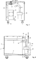
Figur 1 eine perspektivische Darstellung von Teilen der erfindungsgemässen Vorrichtung zum Reinigen eines insbesondere öligen Mediums in Explosionsdarstellung; -
Figur 2 eine perspektivische Ansicht der Vorrichtung gemässFigur 1 in Zusammenbaulage mit abgenommenem Gehäuseblech; -
Figur 3 eine Frontansicht der erfindungsgemässen Vorrichtung gemässFigur 2 mit abgenommenen Innenrahmenblech; -
Figur 4 eine Seitenansicht der erfindungsgemässen Vorrichtung in einem schematisch dargestellten Längsschnitt; -
Figur 5 einen Ausschnitt aus der erfindungsgemässen Vorrichtung gemässFigur 2 . - Gemäss
Figur 2 weist eine erfindungsgemässe Vorrichtung zum Reinigen eines insbesondere öligen Mediums ein Gehäuse 1 auf, welches gemässFigur 1 aus einzelnen Teilen zusammengesetzt ist. Kernstücke sind ein Bodenblech 2, eine Rückwand 3 und ein U-Rahmen 4, welche zusammengesetzt das Gehäuse 1 gemässFigur 2 ausbilden. - In den oberen Bereich des Gehäuse 1 ist ein Rahmen 5 eingesetzt, welcher der Halterung eines Filterträgers 6 dient. In diesen Filterträger 6 kann ein Filter eingelegt werden. Des weiteren weist diese Filterträger 6 Handgriffe 7 auf, mit denen der Filterträger 6 aus dem Gehäuse 1 entnommen und gereinigt werden kann.
- Eine obere Randkante des Gehäuses 1 umläuft eine Dichtung 8, auf die ein Deckel 9 aufgelegt werden kann, so dass ein Innenraum des Gehäuses 1 relativ dicht verschlossen ist.
- Auf einer Frontseite 10 des U-Rahmens 4 befindet sich ein Einlassmittel 11, ein Anschlussnippel 12 und ein Entnahmenippel 13.
- Auf das Gehäuse 1 wird von vorne ein Gehäuseblech 14 aufgeschoben, welches den U-Rahmen umschliesst und durch ein Armaturenblech 15 einen Abstand von der Frontseite 10 herstellt, wodurch ein Raum zwischen Frontseite 10 und einer Frontwand 16 des Gehäuseblechs 14 gebildet wird, in dem sich wesentliche Funktionselemente der Vorrichtung befinden.
- Angedeutet ist noch eine Halterung 17.1 für einen Wagengriff 18, wobei die zweite Halterung gegenüber 17.2 in
Figur 2 dargestellt ist. - Die gesamten Bauelemente gemäss
Figur 1 bilden in Zusammenbaulage eine Einheit, die auf Rollen 19 fahrbar ist und über den Wagengriff 18 bewegt werden kann. - Gemäss den
Figuren 2 bis 4 schliesst an den Einlassnippel 11 ein Schlauchwinkelstück 20 an, welches mit einem Ventil 21 in Verbindung steht. Gegenüberliegend von dem Schlauchwinkelstück 20 führt ein Schlauchstück 22 zu einer Pumpe 23. Von der Pumpe 23 führt ein Anschlussschlauch 24 zum Entnahmenippel 13. - Ein dritter Anschluss 25 ist mit einer Entnahmelanze 26 verbunden, deren Kopfbereich in
Figur 4 angedeutet ist. Allerdings ist die Schlauchverbindung zwischen dem Anschluss 25 und dem Kopfbereich 26 nicht gezeigt. Die Entnahmelanze 26 steckt im übrigen in einer entsprechenden Öffnung in dem Armaturenblech 14 und wird mit der gesamten Einheit mitgeführt. - An den Anschlussnippel 12 schlussendlich schliesst ein Winkelschlauch 27 an, der mit einer Turbine 28 verbunden ist. Turbine 28 und Pumpe 23 sind von einem Innenrahmenblech 29 überdeckt.
- Die Funktionsweise der vorliegenden Erfindung ist Folgende:
Zur Entnahme von z.B. zu reinigendem Frittieröl wird die Entnahmelanze 26 aus dem Gehäuseblech 14 gezogen und in das Öl eingetaucht. Nunmehr wird die Turbine 28 in Gang gesetzt, so dass im Innenraum des Gehäuse 1 ein Unterdruck erzeugt wird. Dies kann unterhalb des Rahmens 5 geschehen, wobei in diesem Fall, wie inFigur 4 gezeigt, der Anschlussnippel 12 von einem Schutzblech 30 abgedeckt ist. - Eine andere Möglichkeit ist in
Figur 5 dargestellt. Dort wird gezeigt, dass von dem Einlassnippel 11 in das Gehäuse 1 ein Rohrwinkel 31 führt. Dieser steht in lösbarer Verbindung mit einem Schnorchel 32, der sich oberhalb des Rahmens 5 für den Filterträger 6 erstreckt. Dabei ist der Filterträger 6 so ausgestaltet, dass bei seinem Einsetzen in das Gehäuse 1 der Schnorchel 32 automatisch auf den Rohrwinkel 31 aufgesetzt wird. - Wird nun die Turbine 28 in Gang gesetzt, wird in dem Gehäuse 1 ein Unterdruck erzeugt über den zu reinigendes Medium durch die Entnahmelanze 26 und über das Schlauchwinkelstück 20 bzw. den Einlassnippel 11 in das Innere des Gehäuses 1 gesaugt wird. Hierdurch wird gewährleistet, dass dem zu reinigenden Öl auf seinem Weg vom Kopf der Entnahmelanze 26 bis zu dem Filter auf dem Filterträger 6 kein Widerstand entgegengesetzt wird, sodass auch grössere Verunreinigungen nicht zerschlagen werden. Ferner hat sich in der Praxis herausgestellt, dass das zu reinigende Medium ideal über die Oberfläche des Filters auf den Filterträger 6 verteilt und, sofern das Vakuum unterhalb des Filters erzeugt wird, sanft und gleichmässig durch den Filter gesaugt wird. Hierdurch entsteht ein sehr ausgeglichener Filterkuchen, der durch diese Saugwirkung bereits vorgetrocknet wird.
- Bei bestimmten Medien und in vielen Fällen hat es sich aber auch als sehr wirkungsvoll erwiesen, wenn die Erzeugung des Vakuums oberhalb der Filteroberfläche stattfindet, so dass da zu filternde Medium durch den Filter unter seiner Schwerkraft hindurchtropft. Hierdurch wird vor allem die Saugkraft durch einen sich zu setzenden Filter nicht beeinflusst. Beide Möglichkeiten sind denkbar und sollen vom Erfindungsgedanken umfasst sein.
- Das gefilterte Medium sammelt sich oberhalb des Bodenblechs 2 an und kann nun, bevorzugt, von Zeit zu Zeit entnommen und zurückgeführt werden. Dies geschieht dadurch, dass das Ventil 21 umgestellt und die Pumpe 23 in Gang gesetzt wird. Diese Pumpe 23 saugt durch den Entnahmenippel 13 das gereinigte Medium an, welches den Anschlussschlauch 24 und das Schlauchstück 22 durchströmt. Da der Weg zu dem Schlauchwinkelstück 20 verschlossen ist, durchströmt das gereinigte Medium den Anschluss 25 zu der Entnahmelanze 26.
- Alle Teile der Vorrichtung sind aus leicht zu reinigendem Material, die wesentlichen Teile aus Edelstahl. Die gesamte Vorrichtung ist so zusammengesetzt, dass sie auch leicht auseinandergenommen und gereinigt werden kann.
Bezugszeichenliste 1 Gehäuse 34 67 2 Bodenblech 35 68 3 Rückwand 36 69 4 U-Rahmen 37 70 5 Rahmen 38 71 6 Filterträger 39 72 7 Hanggriff 40 73 8 Dichtung 41 74 9 Deckel 42 75 10 Frontseite 43 76 11 Einlassnippel 44 77 12 Anschlussnippel 45 78 13 Entnahmenippel 46 79 14 Gehäuseblech 47 15 Armaturblech 48 16 Frontwand 49 17 Halterung 50 18 Wagengriff 51 19 Rollen 52 20 Schlauchwinkelstück 53 21 Ventil 54 22 Schlauchstück 55 23 Pumpe 56 24 Anschlussschlauch 57 25 Anschluss 58 26 Entnahmelanze 59 27 Winkelschlauch 60 28 Turbine 61 29 Innenrahmenblech 62 30 Schutzblech 63 31 Rohrwinkel 64 32 Schnorchel 65 33 66
Claims (13)
- Verfahren zum Reinigen eines insbesondere öligen Mediums aus dem Lebensmittelbereich, insbesondere Frittieröl, mittels einem Filter in einem geschlossenen Gehäuse (1),
dadurch gekennzeichnet,
dass das Medium durch Erzeugen eines Unterdrucks im Gehäuse (1) vor dem Filter angesaugt und auf Grund eigener Gravitation gefiltert wird. - Vorrichtung zur Durchführung des Verfahrens nach Anspruch 1, dadurch gekennzeichnet, dass zum Ansaugen des Mediums dem Gehäuse (1) eine Saugeinrichtung (28) zugeordnet ist und diese einen Anschluss (12) an das Gehäuse (1) unterhalb des Filters aufweist, wobei an den Anschluss (12) ein Schnorchel (32) anschliesst, der durch den Filter geführt ist und oberhalb des Filters ausmündet.
- Vorrichtung nach Anspruch 2, dadurch gekennzeichnet, dass die Saugeinrichtung eine Turbine (28) ist.
- Vorrichtung nach wenigstens einem der vorhergehenden Ansprüche, dadurch gekennzeichnet, dass ein Einlass (11) für das Medium oberhalb des Filters in das Gehäuse (1) einmündet.
- Vorrichtung nach Anspruch 4, dadurch gekennzeichnet, dass der Einlass (11) mit einer Entnahmelanze (26) verbunden ist.
- Vorrichtung nach wenigstens einem der vorhergehenden Ansprüche, dadurch gekennzeichnet, dass im unteren Teil des Gehäuses (1) eine Entnahmeöffnung (13) für das gereinigte Medium vorgesehen ist.
- Vorrichtung nach Anspruch 6, dadurch gekennzeichnet, dass die Entnahmeöffnung (13) mit einer Pumpe (23) in Verbindung steht.
- Vorrichtung nach Anspruch 7, dadurch gekennzeichnet, dass die Pumpe (23) ebenfalls mit der Entnahmelanze (26) verbunden ist.
- Vorrichtung nach Anspruch 8, dadurch gekennzeichnet, dass Entnahmelanze (26) und Einlass (11) für das zu reinigende Medium und Entnahmeöffnung (13) für das gereinigte Medium über ein Wechselventil (21) miteinander in Verbindung stehen.
- Vorrichtung nach wenigstens einem der vorhergehenden Ansprüche, dadurch gekennzeichnet, dass ein Gehäuseboden (2) geneigt ausgebildet ist.
- Vorrichtung nach wenigstens einem der vorhergehenden Ansprüche, dadurch gekennzeichnet, dass der Filter in einem entnehmbaren Filterträger (6) im oberen Bereich des Gehäuses (1) vorgesehen ist.
- Vorrichtung nach wenigstens einem der vorhergehenden Ansprüche, dadurch gekennzeichnet, dass das Gehäuse (1) mit einem Deckel (9) verschlossen ist.
- Vorrichtung nach wenigstens einem der vorhergehenden Ansprüche, dadurch gekennzeichnet, dass das Gehäuse (1) fahrbar ist.
Applications Claiming Priority (2)
| Application Number | Priority Date | Filing Date | Title |
|---|---|---|---|
| DE102013111061.4A DE102013111061A1 (de) | 2013-10-07 | 2013-10-07 | Verfahren zum Reinigen eines insbesondere öligen Mediums |
| PCT/EP2014/002712 WO2015051904A1 (de) | 2013-10-07 | 2014-10-06 | Verfahren und vorrichtung zum filtern von frittieröl |
Publications (2)
| Publication Number | Publication Date |
|---|---|
| EP3054824A1 EP3054824A1 (de) | 2016-08-17 |
| EP3054824B1 true EP3054824B1 (de) | 2019-01-02 |
Family
ID=51786914
Family Applications (1)
| Application Number | Title | Priority Date | Filing Date |
|---|---|---|---|
| EP14786799.8A Active EP3054824B1 (de) | 2013-10-07 | 2014-10-06 | Verfahren und vorrichtung zum filtern von frittieroel |
Country Status (5)
| Country | Link |
|---|---|
| EP (1) | EP3054824B1 (de) |
| DE (1) | DE102013111061A1 (de) |
| ES (1) | ES2712225T3 (de) |
| TR (1) | TR201901498T4 (de) |
| WO (1) | WO2015051904A1 (de) |
Families Citing this family (3)
| Publication number | Priority date | Publication date | Assignee | Title |
|---|---|---|---|---|
| DE102016201120A1 (de) | 2016-01-27 | 2017-07-27 | Schaeffler Technologies AG & Co. KG | Schaltventil für eine Vorrichtung zur Verstellung des Verdichtungsverhältnisses eines Verbrennungsmotors |
| AU2018211243B2 (en) * | 2017-09-06 | 2024-10-10 | Trojan Oils Asset Holdings Pty Ltd | An Improved Liquid Waste Disposal Apparatus |
| WO2022082270A1 (en) * | 2020-10-21 | 2022-04-28 | Intreft Pty Ltd | A waste oil recovery unit |
Family Cites Families (9)
| Publication number | Priority date | Publication date | Assignee | Title |
|---|---|---|---|---|
| US3355026A (en) * | 1966-03-02 | 1967-11-28 | Richard J Schut | Portable filter |
| US4043916A (en) * | 1976-06-16 | 1977-08-23 | Wacker-Dearborn Corporation | On-line closed-vessel circulating filter for edible cooking oils |
| US4282094A (en) * | 1980-01-07 | 1981-08-04 | Charles F. Betz | Filtering apparatus |
| US4462915A (en) | 1981-09-23 | 1984-07-31 | Oil Process Systems, Inc. | Method and system for filtering cooking oil |
| US5839360A (en) * | 1995-06-13 | 1998-11-24 | Williams; David R. | Process of and system for distribution, recovery and handling of bulk edible oil and other fluids |
| DE10049635A1 (de) | 2000-10-05 | 2002-04-11 | Ivona Pasavac | Vorrichtung zum Reinigen von Flüssigkeiten |
| US20040058043A1 (en) * | 2002-09-25 | 2004-03-25 | Ronald More | Portable cleaning and filtering apparatus |
| US7938959B1 (en) * | 2007-07-25 | 2011-05-10 | Inman Restaurant Solutions LLC | Fryer oil usage system |
| US20120318753A1 (en) * | 2011-05-24 | 2012-12-20 | R.F. Hunter Company, Inc. | Food oil vacuum filter system |
-
2013
- 2013-10-07 DE DE102013111061.4A patent/DE102013111061A1/de not_active Withdrawn
-
2014
- 2014-10-06 ES ES14786799T patent/ES2712225T3/es active Active
- 2014-10-06 EP EP14786799.8A patent/EP3054824B1/de active Active
- 2014-10-06 TR TR2019/01498T patent/TR201901498T4/tr unknown
- 2014-10-06 WO PCT/EP2014/002712 patent/WO2015051904A1/de not_active Ceased
Non-Patent Citations (1)
| Title |
|---|
| None * |
Also Published As
| Publication number | Publication date |
|---|---|
| WO2015051904A1 (de) | 2015-04-16 |
| ES2712225T3 (es) | 2019-05-09 |
| TR201901498T4 (tr) | 2019-02-21 |
| EP3054824A1 (de) | 2016-08-17 |
| DE102013111061A1 (de) | 2015-04-09 |
Similar Documents
| Publication | Publication Date | Title |
|---|---|---|
| EP3473937B1 (de) | System und verfahren zum absaugen und filteren von kochdünsten | |
| DE202014004865U1 (de) | Ein Reiniger mit Abwasser-Recycling für harte Oberflächen | |
| DE3235142A1 (de) | Verfahren und vorrichtung zum filtrieren von speiseoel bzw. speisefett | |
| DE6948723U (de) | Aussenfilter fuer aquarien | |
| EP3054824A1 (de) | Verfahren und vorrichtung zum filtern von frittieröl | |
| EP1326692B1 (de) | Vorrichtung zum reinigen von flüssigkeiten | |
| DE1284363B (de) | Vorrichtung zur Beseitigung von auf Wasser schwimmenden fluessigen Stoffen, insbesondere von OEl | |
| DE632698C (de) | Vorrichtung zum Abscheiden von Wasser aus fluessigem Brennstoff | |
| DE2547554C3 (de) | Vorrichtung zum Reinigen von Gegenständen mit Hilfe von Ultraschall | |
| EP0781905A1 (de) | Reinigungsmaschine für kreisläufe von brennkraftmaschinen | |
| DE3103720A1 (de) | Verfahren zum reinigen von gardinen o.dgl. und maschine zur durchfuehrung des verfahrens | |
| DE1189385B (de) | Saugfilter fuer Hydraulikpumpen | |
| EP0041717B1 (de) | Vorrichtung zur Brühwasserreinigung | |
| DE2231498A1 (de) | Filteranordnung fuer filter-pumpenanlagen zum reinigen von badebecken | |
| DE865560C (de) | Filtriereinrichtung fuer galvanische Baeder | |
| DE202013105293U1 (de) | Arbeitstisch zur Maniküre | |
| DE646808C (de) | Filtrier- und Mischgeraet fuer Spritzgut | |
| DE73341C (de) | Vorrichtung zum Lüften, Bewegen und Filtriren des Wassers in Fischbehältern | |
| DE1501811C3 (de) | ölofen mit einem relativ zum Ofen bewegbar angeordneten Brennstoffbehälter | |
| DE1566500C3 (de) | Einrichtung zur Unterwassermassage | |
| DE20023240U1 (de) | Vorrichtung zum Reinigen von Flüssigkeiten | |
| DE954747C (de) | Einrichtung zum Entfernen von Schlamm aus Aquarien | |
| DE2828478A1 (de) | Filter fuer aquarium | |
| DE879912C (de) | Verfahren und Vorrichtung zur Altoelspeicherung in Kraftfahrzeugreparaturwerkstaetten | |
| DE439073C (de) | Absaugevorrichtung fuer Spritzanlagen |
Legal Events
| Date | Code | Title | Description |
|---|---|---|---|
| PUAI | Public reference made under article 153(3) epc to a published international application that has entered the european phase |
Free format text: ORIGINAL CODE: 0009012 |
|
| 17P | Request for examination filed |
Effective date: 20160503 |
|
| AK | Designated contracting states |
Kind code of ref document: A1 Designated state(s): AL AT BE BG CH CY CZ DE DK EE ES FI FR GB GR HR HU IE IS IT LI LT LU LV MC MK MT NL NO PL PT RO RS SE SI SK SM TR |
|
| AX | Request for extension of the european patent |
Extension state: BA ME |
|
| DAX | Request for extension of the european patent (deleted) | ||
| GRAP | Despatch of communication of intention to grant a patent |
Free format text: ORIGINAL CODE: EPIDOSNIGR1 |
|
| STAA | Information on the status of an ep patent application or granted ep patent |
Free format text: STATUS: GRANT OF PATENT IS INTENDED |
|
| INTG | Intention to grant announced |
Effective date: 20180814 |
|
| GRAS | Grant fee paid |
Free format text: ORIGINAL CODE: EPIDOSNIGR3 |
|
| GRAA | (expected) grant |
Free format text: ORIGINAL CODE: 0009210 |
|
| STAA | Information on the status of an ep patent application or granted ep patent |
Free format text: STATUS: THE PATENT HAS BEEN GRANTED |
|
| AK | Designated contracting states |
Kind code of ref document: B1 Designated state(s): AL AT BE BG CH CY CZ DE DK EE ES FI FR GB GR HR HU IE IS IT LI LT LU LV MC MK MT NL NO PL PT RO RS SE SI SK SM TR |
|
| REG | Reference to a national code |
Ref country code: GB Ref legal event code: FG4D Free format text: NOT ENGLISH |
|
| REG | Reference to a national code |
Ref country code: CH Ref legal event code: EP Ref country code: AT Ref legal event code: REF Ref document number: 1083348 Country of ref document: AT Kind code of ref document: T Effective date: 20190115 |
|
| REG | Reference to a national code |
Ref country code: IE Ref legal event code: FG4D Free format text: LANGUAGE OF EP DOCUMENT: GERMAN |
|
| REG | Reference to a national code |
Ref country code: DE Ref legal event code: R096 Ref document number: 502014010552 Country of ref document: DE |
|
| REG | Reference to a national code |
Ref country code: CH Ref legal event code: NV Representative=s name: ARIE WUBBEN C/O MEDIPACK AG, CH |
|
| REG | Reference to a national code |
Ref country code: NL Ref legal event code: MP Effective date: 20190102 |
|
| REG | Reference to a national code |
Ref country code: ES Ref legal event code: FG2A Ref document number: 2712225 Country of ref document: ES Kind code of ref document: T3 Effective date: 20190509 |
|
| REG | Reference to a national code |
Ref country code: LT Ref legal event code: MG4D |
|
| PG25 | Lapsed in a contracting state [announced via postgrant information from national office to epo] |
Ref country code: NL Free format text: LAPSE BECAUSE OF FAILURE TO SUBMIT A TRANSLATION OF THE DESCRIPTION OR TO PAY THE FEE WITHIN THE PRESCRIBED TIME-LIMIT Effective date: 20190102 |
|
| PG25 | Lapsed in a contracting state [announced via postgrant information from national office to epo] |
Ref country code: PL Free format text: LAPSE BECAUSE OF FAILURE TO SUBMIT A TRANSLATION OF THE DESCRIPTION OR TO PAY THE FEE WITHIN THE PRESCRIBED TIME-LIMIT Effective date: 20190102 Ref country code: LT Free format text: LAPSE BECAUSE OF FAILURE TO SUBMIT A TRANSLATION OF THE DESCRIPTION OR TO PAY THE FEE WITHIN THE PRESCRIBED TIME-LIMIT Effective date: 20190102 Ref country code: PT Free format text: LAPSE BECAUSE OF FAILURE TO SUBMIT A TRANSLATION OF THE DESCRIPTION OR TO PAY THE FEE WITHIN THE PRESCRIBED TIME-LIMIT Effective date: 20190502 Ref country code: FI Free format text: LAPSE BECAUSE OF FAILURE TO SUBMIT A TRANSLATION OF THE DESCRIPTION OR TO PAY THE FEE WITHIN THE PRESCRIBED TIME-LIMIT Effective date: 20190102 Ref country code: SE Free format text: LAPSE BECAUSE OF FAILURE TO SUBMIT A TRANSLATION OF THE DESCRIPTION OR TO PAY THE FEE WITHIN THE PRESCRIBED TIME-LIMIT Effective date: 20190102 Ref country code: NO Free format text: LAPSE BECAUSE OF FAILURE TO SUBMIT A TRANSLATION OF THE DESCRIPTION OR TO PAY THE FEE WITHIN THE PRESCRIBED TIME-LIMIT Effective date: 20190402 |
|
| PG25 | Lapsed in a contracting state [announced via postgrant information from national office to epo] |
Ref country code: BG Free format text: LAPSE BECAUSE OF FAILURE TO SUBMIT A TRANSLATION OF THE DESCRIPTION OR TO PAY THE FEE WITHIN THE PRESCRIBED TIME-LIMIT Effective date: 20190402 Ref country code: GR Free format text: LAPSE BECAUSE OF FAILURE TO SUBMIT A TRANSLATION OF THE DESCRIPTION OR TO PAY THE FEE WITHIN THE PRESCRIBED TIME-LIMIT Effective date: 20190403 Ref country code: LV Free format text: LAPSE BECAUSE OF FAILURE TO SUBMIT A TRANSLATION OF THE DESCRIPTION OR TO PAY THE FEE WITHIN THE PRESCRIBED TIME-LIMIT Effective date: 20190102 Ref country code: IS Free format text: LAPSE BECAUSE OF FAILURE TO SUBMIT A TRANSLATION OF THE DESCRIPTION OR TO PAY THE FEE WITHIN THE PRESCRIBED TIME-LIMIT Effective date: 20190502 Ref country code: HR Free format text: LAPSE BECAUSE OF FAILURE TO SUBMIT A TRANSLATION OF THE DESCRIPTION OR TO PAY THE FEE WITHIN THE PRESCRIBED TIME-LIMIT Effective date: 20190102 Ref country code: RS Free format text: LAPSE BECAUSE OF FAILURE TO SUBMIT A TRANSLATION OF THE DESCRIPTION OR TO PAY THE FEE WITHIN THE PRESCRIBED TIME-LIMIT Effective date: 20190102 |
|
| REG | Reference to a national code |
Ref country code: DE Ref legal event code: R097 Ref document number: 502014010552 Country of ref document: DE |
|
| PG25 | Lapsed in a contracting state [announced via postgrant information from national office to epo] |
Ref country code: AL Free format text: LAPSE BECAUSE OF FAILURE TO SUBMIT A TRANSLATION OF THE DESCRIPTION OR TO PAY THE FEE WITHIN THE PRESCRIBED TIME-LIMIT Effective date: 20190102 Ref country code: RO Free format text: LAPSE BECAUSE OF FAILURE TO SUBMIT A TRANSLATION OF THE DESCRIPTION OR TO PAY THE FEE WITHIN THE PRESCRIBED TIME-LIMIT Effective date: 20190102 Ref country code: CZ Free format text: LAPSE BECAUSE OF FAILURE TO SUBMIT A TRANSLATION OF THE DESCRIPTION OR TO PAY THE FEE WITHIN THE PRESCRIBED TIME-LIMIT Effective date: 20190102 Ref country code: EE Free format text: LAPSE BECAUSE OF FAILURE TO SUBMIT A TRANSLATION OF THE DESCRIPTION OR TO PAY THE FEE WITHIN THE PRESCRIBED TIME-LIMIT Effective date: 20190102 Ref country code: SK Free format text: LAPSE BECAUSE OF FAILURE TO SUBMIT A TRANSLATION OF THE DESCRIPTION OR TO PAY THE FEE WITHIN THE PRESCRIBED TIME-LIMIT Effective date: 20190102 Ref country code: DK Free format text: LAPSE BECAUSE OF FAILURE TO SUBMIT A TRANSLATION OF THE DESCRIPTION OR TO PAY THE FEE WITHIN THE PRESCRIBED TIME-LIMIT Effective date: 20190102 |
|
| PLBE | No opposition filed within time limit |
Free format text: ORIGINAL CODE: 0009261 |
|
| STAA | Information on the status of an ep patent application or granted ep patent |
Free format text: STATUS: NO OPPOSITION FILED WITHIN TIME LIMIT |
|
| PG25 | Lapsed in a contracting state [announced via postgrant information from national office to epo] |
Ref country code: SM Free format text: LAPSE BECAUSE OF FAILURE TO SUBMIT A TRANSLATION OF THE DESCRIPTION OR TO PAY THE FEE WITHIN THE PRESCRIBED TIME-LIMIT Effective date: 20190102 |
|
| 26N | No opposition filed |
Effective date: 20191003 |
|
| PG25 | Lapsed in a contracting state [announced via postgrant information from national office to epo] |
Ref country code: SI Free format text: LAPSE BECAUSE OF FAILURE TO SUBMIT A TRANSLATION OF THE DESCRIPTION OR TO PAY THE FEE WITHIN THE PRESCRIBED TIME-LIMIT Effective date: 20190102 |
|
| PG25 | Lapsed in a contracting state [announced via postgrant information from national office to epo] |
Ref country code: MC Free format text: LAPSE BECAUSE OF FAILURE TO SUBMIT A TRANSLATION OF THE DESCRIPTION OR TO PAY THE FEE WITHIN THE PRESCRIBED TIME-LIMIT Effective date: 20190102 |
|
| PG25 | Lapsed in a contracting state [announced via postgrant information from national office to epo] |
Ref country code: LU Free format text: LAPSE BECAUSE OF NON-PAYMENT OF DUE FEES Effective date: 20191006 |
|
| PG25 | Lapsed in a contracting state [announced via postgrant information from national office to epo] |
Ref country code: IE Free format text: LAPSE BECAUSE OF NON-PAYMENT OF DUE FEES Effective date: 20191006 |
|
| REG | Reference to a national code |
Ref country code: AT Ref legal event code: MM01 Ref document number: 1083348 Country of ref document: AT Kind code of ref document: T Effective date: 20191006 |
|
| PG25 | Lapsed in a contracting state [announced via postgrant information from national office to epo] |
Ref country code: AT Free format text: LAPSE BECAUSE OF NON-PAYMENT OF DUE FEES Effective date: 20191006 |
|
| PG25 | Lapsed in a contracting state [announced via postgrant information from national office to epo] |
Ref country code: CY Free format text: LAPSE BECAUSE OF FAILURE TO SUBMIT A TRANSLATION OF THE DESCRIPTION OR TO PAY THE FEE WITHIN THE PRESCRIBED TIME-LIMIT Effective date: 20190102 |
|
| PG25 | Lapsed in a contracting state [announced via postgrant information from national office to epo] |
Ref country code: HU Free format text: LAPSE BECAUSE OF FAILURE TO SUBMIT A TRANSLATION OF THE DESCRIPTION OR TO PAY THE FEE WITHIN THE PRESCRIBED TIME-LIMIT; INVALID AB INITIO Effective date: 20141006 Ref country code: MT Free format text: LAPSE BECAUSE OF FAILURE TO SUBMIT A TRANSLATION OF THE DESCRIPTION OR TO PAY THE FEE WITHIN THE PRESCRIBED TIME-LIMIT Effective date: 20190102 |
|
| PG25 | Lapsed in a contracting state [announced via postgrant information from national office to epo] |
Ref country code: MK Free format text: LAPSE BECAUSE OF FAILURE TO SUBMIT A TRANSLATION OF THE DESCRIPTION OR TO PAY THE FEE WITHIN THE PRESCRIBED TIME-LIMIT Effective date: 20190102 |
|
| REG | Reference to a national code |
Ref country code: CH Ref legal event code: U11 Free format text: ST27 STATUS EVENT CODE: U-0-0-U10-U11 (AS PROVIDED BY THE NATIONAL OFFICE) Effective date: 20260212 |
|
| PGFP | Annual fee paid to national office [announced via postgrant information from national office to epo] |
Ref country code: GB Payment date: 20260212 Year of fee payment: 12 |
|
| PGFP | Annual fee paid to national office [announced via postgrant information from national office to epo] |
Ref country code: ES Payment date: 20260217 Year of fee payment: 12 |
|
| PGFP | Annual fee paid to national office [announced via postgrant information from national office to epo] |
Ref country code: DE Payment date: 20260209 Year of fee payment: 12 |
|
| PGFP | Annual fee paid to national office [announced via postgrant information from national office to epo] |
Ref country code: BE Payment date: 20260218 Year of fee payment: 12 Ref country code: IT Payment date: 20260227 Year of fee payment: 12 |
|
| PGFP | Annual fee paid to national office [announced via postgrant information from national office to epo] |
Ref country code: FR Payment date: 20260219 Year of fee payment: 12 |
|
| PGFP | Annual fee paid to national office [announced via postgrant information from national office to epo] |
Ref country code: TR Payment date: 20260220 Year of fee payment: 12 |
|
| PGFP | Annual fee paid to national office [announced via postgrant information from national office to epo] |
Ref country code: CH Payment date: 20260212 Year of fee payment: 12 |