EP3053711B1 - Robot hand controlling method and robotics device - Google Patents
Robot hand controlling method and robotics device Download PDFInfo
- Publication number
- EP3053711B1 EP3053711B1 EP16153094.4A EP16153094A EP3053711B1 EP 3053711 B1 EP3053711 B1 EP 3053711B1 EP 16153094 A EP16153094 A EP 16153094A EP 3053711 B1 EP3053711 B1 EP 3053711B1
- Authority
- EP
- European Patent Office
- Prior art keywords
- fingers
- grip force
- grip
- work
- robot hand
- Prior art date
- Legal status (The legal status is an assumption and is not a legal conclusion. Google has not performed a legal analysis and makes no representation as to the accuracy of the status listed.)
- Active
Links
- 238000000034 method Methods 0.000 title claims description 100
- 230000007246 mechanism Effects 0.000 claims description 5
- 230000005540 biological transmission Effects 0.000 claims description 4
- 230000008569 process Effects 0.000 description 63
- 230000033001 locomotion Effects 0.000 description 16
- 238000003780 insertion Methods 0.000 description 9
- 230000037431 insertion Effects 0.000 description 9
- 238000006243 chemical reaction Methods 0.000 description 8
- 238000005259 measurement Methods 0.000 description 8
- 230000008859 change Effects 0.000 description 7
- 238000010586 diagram Methods 0.000 description 7
- 238000004891 communication Methods 0.000 description 5
- 230000006870 function Effects 0.000 description 5
- 230000003044 adaptive effect Effects 0.000 description 3
- 238000002474 experimental method Methods 0.000 description 3
- 230000007704 transition Effects 0.000 description 3
- 238000013461 design Methods 0.000 description 2
- 238000012545 processing Methods 0.000 description 2
- 230000001419 dependent effect Effects 0.000 description 1
- 238000001514 detection method Methods 0.000 description 1
- 238000011161 development Methods 0.000 description 1
- 230000018109 developmental process Effects 0.000 description 1
- 238000004519 manufacturing process Methods 0.000 description 1
- 238000012986 modification Methods 0.000 description 1
- 230000004048 modification Effects 0.000 description 1
- 230000003287 optical effect Effects 0.000 description 1
- 230000000704 physical effect Effects 0.000 description 1
- 230000009467 reduction Effects 0.000 description 1
- 230000004044 response Effects 0.000 description 1
- 230000003068 static effect Effects 0.000 description 1
- 230000002123 temporal effect Effects 0.000 description 1
- 238000012360 testing method Methods 0.000 description 1
Images


Classifications
-
- B—PERFORMING OPERATIONS; TRANSPORTING
- B25—HAND TOOLS; PORTABLE POWER-DRIVEN TOOLS; MANIPULATORS
- B25J—MANIPULATORS; CHAMBERS PROVIDED WITH MANIPULATION DEVICES
- B25J9/00—Programme-controlled manipulators
- B25J9/16—Programme controls
- B25J9/1612—Programme controls characterised by the hand, wrist, grip control
-
- B—PERFORMING OPERATIONS; TRANSPORTING
- B25—HAND TOOLS; PORTABLE POWER-DRIVEN TOOLS; MANIPULATORS
- B25J—MANIPULATORS; CHAMBERS PROVIDED WITH MANIPULATION DEVICES
- B25J15/00—Gripping heads and other end effectors
- B25J15/02—Gripping heads and other end effectors servo-actuated
- B25J15/0253—Gripping heads and other end effectors servo-actuated comprising parallel grippers
- B25J15/026—Gripping heads and other end effectors servo-actuated comprising parallel grippers actuated by gears
-
- B—PERFORMING OPERATIONS; TRANSPORTING
- B25—HAND TOOLS; PORTABLE POWER-DRIVEN TOOLS; MANIPULATORS
- B25J—MANIPULATORS; CHAMBERS PROVIDED WITH MANIPULATION DEVICES
- B25J15/00—Gripping heads and other end effectors
- B25J15/08—Gripping heads and other end effectors having finger members
-
- G—PHYSICS
- G05—CONTROLLING; REGULATING
- G05B—CONTROL OR REGULATING SYSTEMS IN GENERAL; FUNCTIONAL ELEMENTS OF SUCH SYSTEMS; MONITORING OR TESTING ARRANGEMENTS FOR SUCH SYSTEMS OR ELEMENTS
- G05B2219/00—Program-control systems
- G05B2219/30—Nc systems
- G05B2219/39—Robotics, robotics to robotics hand
- G05B2219/39478—Control force and posture of hand
-
- G—PHYSICS
- G05—CONTROLLING; REGULATING
- G05B—CONTROL OR REGULATING SYSTEMS IN GENERAL; FUNCTIONAL ELEMENTS OF SUCH SYSTEMS; MONITORING OR TESTING ARRANGEMENTS FOR SUCH SYSTEMS OR ELEMENTS
- G05B2219/00—Program-control systems
- G05B2219/30—Nc systems
- G05B2219/39—Robotics, robotics to robotics hand
- G05B2219/39505—Control of gripping, grasping, contacting force, force distribution
-
- Y—GENERAL TAGGING OF NEW TECHNOLOGICAL DEVELOPMENTS; GENERAL TAGGING OF CROSS-SECTIONAL TECHNOLOGIES SPANNING OVER SEVERAL SECTIONS OF THE IPC; TECHNICAL SUBJECTS COVERED BY FORMER USPC CROSS-REFERENCE ART COLLECTIONS [XRACs] AND DIGESTS
- Y10—TECHNICAL SUBJECTS COVERED BY FORMER USPC
- Y10S—TECHNICAL SUBJECTS COVERED BY FORMER USPC CROSS-REFERENCE ART COLLECTIONS [XRACs] AND DIGESTS
- Y10S901/00—Robots
- Y10S901/30—End effector
- Y10S901/31—Gripping jaw
- Y10S901/36—Actuating means
Definitions
- the present invention relates to a robot hand controlling method according to the preamble of claim 1 and a robotics device that control a robot hand.
- a robotics device including a robot hand is used as an industrial robot to advance the automation of product assembly conventionally performed by manpower.
- the robot hand is used to handle a work to assemble a variety of products, the work needs to be surely gripped without breaking or dropping the work, regardless of the physical properties of the work.
- enabling to easily control the grip force of the robot hand is demanded to accurately grip the work in order to realize further advanced product assembly using the industrial robot.
- a method of using a disturbance estimation observer to control the grip force of the robot hand (see JP 2002-178281 A ) is proposed as an example of a method of controlling the grip force.
- a grip apparatus to grip the work in a grip force controlling apparatus disclosed in JP 2002-178281 A
- the driving current and the rotating speed of a motor that provides the grip force are input, and the disturbance estimation observer outputs an estimation value of the grip force of the robot hand.
- the grip force controlling apparatus disclosed in JP 2002-178281 A performs control of eliminating the deviation between the grip force estimation value output from the disturbance estimation observer and a grip force target value to thereby control the grip force of the robot hand.
- JP 2002-178281 A frictional force generated in a driving mechanism that drives fingers is switched from static friction to kinetic friction and is significantly changed in a transition from a state in which the movement speed of the fingers of the robot hand is 0 to a state in which a motor begins to revolve. Therefore, a compensation coefficient of the disturbance estimation observer for estimating the influence of the friction cannot be uniquely identified.
- hysteresis i.e. dead zone that cannot be controlled, is provided to the compensation coefficient of the disturbance estimation observer for estimating the influence of the friction when the movement speed of the fingers is 0 and when the movement speed of the fingers is not 0. Therefore, in JP 2002-178281 A , accurate adjustment and control of the grip force of the robot hand is difficult in the state that the robot hand is gripping the work.
- a method of using an external force sensor that can measure the grip force and controlling the grip force while measuring the grip force of the robot hand can be considered.
- a member for causing the external force sensor to detect the grip force needs to be separately provided to the robot hand in this case, and downsizing of the robot hand is difficult.
- the force sensor is generally more expensive than a sensor capable of measuring a position, and reduction in the cost of the robot hand is also difficult.
- the measurement accuracy of the force sensor is lower than that of a position sensor or the like, and accurate adjustment and control of the grip force of the robot hand is difficult.
- the expert article of Mark D The expert article of Mark D.
- Hanes et al "Intelligent Control of Object Acquisition for Power Grasp", 1994 IEEE International Symposium on Intelligent Control, Columbus, Ohio, USA , shows a generic controlling method of a robot hand according to the preamble of claim 1.
- the expert article of Kai-Tai Song et al "A Fuzzy Adaptive Control Design for Compliant Motion of a Manipulator", International Conference on Industrial Electronics, Control and Instrumentation, 5 to 9 September 1994, Bologna, Italy , shows a fuzzy adaptive control design for a compliant motion of a manipulator in order to compensate a deviation between an actual contact force and a desired contact force by using a fuzzy adaptive force controller (i.e. a fuzzy PI controller), wherein the response of the fuzzy PI controller is faster than that of a fuzzy controller without adaption.
- a fuzzy adaptive force controller i.e. a fuzzy PI controller
- the object of the present invention is achieved by a robot hand controlling method having the features of claim 1 and a robotics device having the features of claim 6.
- the grip force can be changed by calculating the driving quantity of the actuator from the position of the plurality of fingers in gripping the work with the changed grip force, the grip force can be accurately adjusted.
- FIG. 1 is a schematic diagram illustrating a schematic configuration of a robotics device according to the embodiment of the present invention.
- a robotics device 1 includes: a robot hand 10 capable of grasping a work W (see FIG. 2 ); and a robot arm 20 including the robot hand 10 at a tip, the robot arm 20 controlling the position of the robot hand 10 and including a plurality of joints.
- the robotics device 1 further includes: a hand controlling unit 30 as a controlling unit that controls the robot hand 10; and a controlling instruction unit 40 capable of transmitting various controlling instructions.
- the robotics device 1 further includes a power controlling unit 50 that supplies power to the elements included in the robotics device 1 through power supply cables 51.
- the controlling instruction unit 40 is connected to the hand controlling unit 30 through a communication cable 41 and transmits a controlling instruction for opening and closing fingers 11a and 11b (see FIG. 2 ) of the robot hand 10 to the hand controlling unit 30 through the communication cable 41 to open and close the fingers 11a and 11b.
- Communication between the hand controlling unit 30 and the controlling instruction unit 40 is performed by, for example, parallel I/O or high-speed differential serial communication with high resistance to noise.
- the controlling instruction unit 40 is connected to an arm controlling unit not illustrated included in the robot arm 20 through an arm cable 42 and transmits a controlling instruction for operating the joints to the arm controlling unit through the arm cable 42 to operate the robot arm 20. More specifically, the controlling instruction unit 40 can control the robot hand 10 and the robot arm 20 and serve as a robot system to grip and assemble components to realize product assembly. The details of control executed by the controlling instruction unit 40 and the controlling instructions transmitted to the hand controlling unit 30 by the controlling instruction unit 40 are designed in advance by the user in JOB programs of product assembly operation of the robot system and are stored in a memory of the controlling instruction unit 40.
- the robot arm 20 may include a plurality of arm controlling units that controls operation of each joint.
- the power controlling unit 50 is connected to an external power supply provided outside of the robotics device 1 through the power supply cable 51 and adjusts the power supplied from the external power supply to supply necessary power to the hand controlling unit 30, the controlling instruction unit 40 and the like.
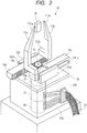
- FIG. 2 is a diagram illustrating a configuration of the robot hand 10.
- the robot hand 10 includes: the pair of fingers 11a and 11b capable of grasping the work W; and a motor 12 as an actuator that generates driving force.
- the robot hand 10 further includes a pair of linear guides 13a and 13b, a pair of rack gears 14a and 14b and a pinion gear 15 that are driving force transmission mechanisms for moving the fingers 11a and 11b based on a movement quantity according to a driving quantity of the motor 12.
- the fingers 11a and 11b have a tweezer shape and include: contact portions 111a and 111b that come into contact with the work W to grip the work W; and fixing portions 112a and 112b fixed to the rack gears 14a and 14b.
- the fingers 11a and 11b move in a direction for griping the work W and in a direction away from the work W according to the movement of the rack gears 14a and 14b.
- the motor 12 is, for example, a three-phase AC servo motor and is attached to a lower surface of a base plate 16.
- the motor 12 includes: a decelerator 17 that amplifies output torque of the motor 12; and an encoder circuit 18 as a sensor that detects the number of rotations and the rotation angle of the motor 12.
- the motor 12 is connected to the hand controlling unit 30 through hand cables 31.
- the hand cables 31 include: encoder signal lines 31a for transmitting output signals output from the encoder circuit 18 to the hand controlling unit 30; and motor power lines 31b for supplying driving current to the motor 12.
- the encoder signal lines 31a include five lines for power supply of the encoder circuit 18, GND, and an A phase, a B phase and a Z phase of the output signals of the encoder, for example.
- the motor power lines 31b are power lines corresponding to the type of the motor 12 and include three power lines connected to a U phase, a V phase and a W phase when the motor 12 is, for example, a three-phase AC servo motor.
- the pair of linear guides 13a and 13b is attached to an upper surface of the base plate 16 and include guide grooves 19a and 19b on surfaces opposite to each other.
- the pair of rack gears 14a and 14b include guide protrusions 141a and 141b in a protrusion shape fitted to the guide grooves 19a and 19b of the linear guides 13a and 13b, on surfaces opposite to tooth surfaces of the gears.
- the guide protrusions 141a and 141b are fitted to the guide grooves 19a and 19b and attached to the linear guides 13a and 13b. In this way, the rack gears 14a and 14b can move the fingers 11a and 11b in parallel in the open and close directions for contacting and separating the fingers 11a and 11b.
- the pinion gear 15 is attached to a driving shaft of the motor 12 and is engaged with gear tooth surfaces of the rack gears 14a and 14b. In this way, the robot hand 10 can drive the motor 12 to normally and reversely rotate the pinion gear 15 to move the rack gears 14a and 14b in parallel to open and close the fingers 11a and 11b.
- the hand controlling unit 30 includes: a CPU 301 capable of calculating a program; a ROM 302 and a RAM 303 functioning as storage units capable of storage; and an HDD (hard disk drive) 304 as a recording medium.
- the hand controlling unit 30 further includes various interfaces 305 to 307 and a motor driver 308.
- the ROM 302, the RAM 303, the HDD 304 and the various interfaces 305 to 307 are connected to the CPU 301 through a bus 310.
- data of various programs and filters for operating the CPU 301 is stored in the HDD 304 (or may be an external storage apparatus 322).
- an instruction value conversion program 304a is a program for the CPU 301 to convert controlling instructions transmitted from the controlling instruction unit 40 into parameters necessary for servo calculation. Specifically, controlling instructions, such as position, speed, grip force and grip level, transmitted from the controlling instruction unit 40 are converted into parameters, such as position, speed and current value.
- the controlling instruction based on the grip level is, for example, a controlling instruction for designating the grip force in ten stages of level 1 to 10 when the specification of the maximum grip force of the robot hand 10 is 50N.
- a controlling instruction of grip force 5N can be transmitted in a controlling instruction of grip level 1
- a controlling instruction of grip force 50N can be transmitted in a controlling instruction of grip level 10.
- a servo calculation parameter 304b is a parameter used as necessary when the CPU 301 executes servo calculation and includes, for example, a parameter of PID gain used for calculating the motor driving current.
- the motor 12 included in the robot hand 10 is connected to the interface 305 through the hand cables 31, and the motor driver 308 is connected to the interface 306.
- the external storage apparatus (for example, an external HDD or a non-volatile memory) 322 is connected to the interface 307.
- the CPU 301 uses the parameters converted by the instruction value conversion program 304a, the output signal received from the encoder circuit 18 and the motor driving current to execute servo calculation and outputs a motor driving signal to the motor driver 308.
- the motor driver 308 includes a half-bridge circuit of U phase, V phase and W phase that is a detection circuit of the motor driving current.
- the motor driving signal is a PWM (Pulse Width Modulation) signal for driving the half-bridge circuit included in the motor driver 308.
- the motor driver 308 activates the built-in half-bridge circuit according to a driver driving signal and supplies a motor driving current to the motor 12 through the hand cables 31 to drive the motor 12.
- the robotics device 1 can cause the hand controlling unit 30 to calculate the controlling instruction transmitted from the controlling instruction unit 40 and drive the motor 12 through the motor driver 308 based on the calculation result to cause the fingers 11a and 11b to grip the work W with desired grip force.
- the hand controlling unit 30 first executes setting first grip force in gripping the work W when the fingers 11a and 11b are not gripping the work W (open state).
- the first grip force is used to calculate the motor driving current and the motor rotating speed of the motor 12, and the motor 12 is driven based on the calculated motor driving current and motor rotating speed.
- the hand controlling unit 30 then executes causing the fingers 11a and 11b to grip the work W.
- calculating a position is first executed when the grip force is to be changed while the fingers 11a and 11b are gripping the work W (closed state) with the first grip force.
- a correlation value indicating the relationship between the grip force of the fingers 11a and 11b and the position of the fixing portions 112a and 112b, the first grip force, and second grip force that is a target value of the grip force are used to calculate the position of the fixing portions 112a and 112b in gripping the work W with the second grip force.
- the hand controlling unit 30 then executes changing grip force of driving the motor 12 by calculating a driving quantity of the motor 12 necessary to move the fixing portions 112a and 112b to the calculated position of the fixing portions 112a and 112b.
- FIG. 4 is a flow chart illustrating grip control executed by the hand controlling unit 30.
- the grip control is executed according to a robot hand controlling program set in advance by the user.
- the grip control is executed in the state before the work W is gripped and in the state that the work W is gripped, after the position of the robot hand 10 and the robot arm 20 is controlled such that the work W to be gripped is positioned between the fingers 11a and 11b of the robot hand 10.
- the CPU 301 of the hand controlling unit 30 receives a controlling instruction from the controlling instruction unit 40, the controlling instruction indicating grip force F n that is target grip force when the fingers 11a and 11b grip the work W (S11).
- the CPU 301 receives the controlling instruction of the grip force F n from the controlling instruction unit 40 and stores, in the RAM 303, a controlling instruction of grip force F n-1 received from the controlling instruction unit 40 the last time.
- the process of step S11 by the hand controlling unit 30 comprises setting grip force.
- the CPU 301 determines whether the grip force F n-1 stored in the RAM 303 is 0 (S12). In this process, the CPU 301 determines whether the grip control of this time is a gripping process executed in the open state or a grip adjustment process executed when the fingers 11a and 11b are in the closed state.
- the CPU 301 determines that the process is the gripping process executed in the open state and reads the instruction value conversion program 304a from the HDD 304.
- the CPU 301 sets a motor driving current I and a motor rotating speed v according to the instruction value conversion program 304a (S13) .
- the CPU 301 uses an initial grip conversion table saved in advance in the ROM 302 and reads the motor driving current I [A] and the motor rotating speed v [rpm] corresponding to the target grip forced F n [N] according to the instruction value conversion program 304a.
- the CPU 301 stores, in the RAM 303, the read motor driving current I and motor rotating speed v as parameters obtained by converting the controlling instructions received from the controlling instruction unit 40 based on the instruction value conversion program 304a.
- the initial grip here denotes gripping the work W by the fingers 11a and 11b from the open state.
- the initial grip conversion table is a data table created from data of a relationship between the motor driving current I [A], the motor rotating speed v [rpm] and the grip force [N] obtained in advance by an experiment.
- the method of setting the motor driving current I and the motor rotating speed v is not limited to the method of using the conversion table.
- the CPU 301 may calculate an approximate formula for deriving the relationship between the motor driving current I, the motor rotating speed v and the grip force F based on experimental data obtained in advance and use the approximate formula to calculate the motor driving current I and the motor rotating speed v.
- the grip force F n in the initial grip that is received by the hand controlling unit 30 from the controlling instruction unit 40 and that is set as the grip force of the fingers 11a and 11b is the first grip force according to the present embodiment.
- the CPU 301 uses the motor driving current I and the motor rotating speed v stored in the RAM 303 in step S13 to perform servo calculation and outputs a motor driving signal to the motor driver 308.
- the motor driver 308 supplies a motor driving current based on the motor driving signal to the motor 12 to drive the motor 12 (S14).
- the CPU 301 drives the motor 12 with the calculated motor driving current I and motor rotating speed v through the motor driver 308 and drives the motor 12 to put the fingers 11a and 11b in the open state into the closed state. In this way, the CPU 301 can cause the fingers 11a and 11b to grip the work W with the target grip force F n .
- the CPU 301 determines whether the received output signal of the number of rotations and the rotation angle of the motor 12 output from the encoder circuit 18 is changed from the output signal received the last time (S15). In this process, the CPU 301 determines the change in the output signal to determine whether the fingers 11a and 11b come into contact with the work W so that the movement of the fingers 11a and 11b is stopped, that is, the drive of the motor 12 is stopped, in balance with reaction force from the work W. In this process, if the CPU 301 determines that the received output signal is changed from the output signal received the last time (Yes), the CPU 301 repeats the process of step S15.
- step S15 if there is no change in the received output signal or if the difference between the received output signal and the output signal received the last time is lower than a specific threshold (No), the CPU 301 advances the process to step S19.
- the case in which the process of step S15 is No corresponds to a state in which gripping is finished, and details will be described later.
- the CPU 301 determines that the grip force F n-1 is not 0 in the process of step S12 (No), the CPU 301 executes a grip force adjustment process described below that is a process executed in the closed state.
- the grip force F n set as the grip force of the fingers 11a and 11b is set by the controlling instruction unit 40 transmitting corresponding data and the hand controlling unit 30 receiving the data, and the grip force F n is the second grip force according to the present embodiment.
- the current grip force F n-1 stored in the RAM 303 is the first grip force according to the present embodiment.
- An example of the case in which the grip force adjustment process is executed includes fitting operation of fitting a soft cap-like component into a boss of a main work.
- the cap-like component may be deformed and may not be able to be fitted due to a mismatch with the shape of the boss.
- the component needs to be gripped with low grip force, and the position needs to be adjusted to the position of the boss while preventing the deformation. Therefore, at the execution of the fitting operation, the robotics device 1 adjusts the grip force to higher grip force after the opening of the cap-like component gripped with the low grip force is hooked to the tip of the boss.
- the robotics device 1 then pushes and fits the component into the root of the boss.
- An example of the case in which the grip force adjustment process is executed includes insertion operation in which a rigid rod-shaped component is inserted to a similarly rigid main work.
- insertion operation high positioning accuracy is required in fitting the rigid bodies.
- the absolute position accuracy of the robotics device is lower than the required positioning accuracy, the rod-shaped component and the main work may interfere with each other, and a flaw may be generated.
- the robotics device 1 first stabilizes and grips the rod-shaped component with high grip force and quickly adjusts the position to the insertion hole of the main work to put the rod-shaped component into the tip of the insertion hole.
- the robotics device 1 then adjusts the grip force to low grip force and inserts the rod-shaped component into the insertion hole while preventing excessive interference of the rod-shaped component with the insertion hole of the main work.
- the CPU 301 reads the instruction value conversion program 304a from the HDD 304.
- the CPU 301 sets a movement quantity ⁇ d of the fixing portions 112a and 112b of the fingers 11a and 11b according to the instruction value conversion program 304a.
- the CPU 301 uses a value of a current position do of the fixing portions 112a and 112b corresponding to the current grip force F n-1 and a value of the movement quantity ⁇ d of the fixing portions 112a and 112b to calculate an instruction value d of position control (S16).
- the process of step S16 by the hand controlling unit 30 comprises the calculating the position according to the present embodiment.
- the CPU 301 first calculates ⁇ F that is a difference between the current grip force F n-1 stored in the RAM 303 and the target grip force F n included in the controlling instruction received from the controlling instruction unit 40.
- the CPU 301 calculates the current position do of the fixing portions 112a and 112b corresponding to the current grip force F n-1 from the output signal received from the encoder circuit 18 according to the instruction value conversion program 304a.
- the CPU 301 uses the grip force adjustment conversion table saved in advance in the ROM 302 and sets the movement quantity ⁇ d [mm] of the fixing portions 112a and 112b corresponding to ⁇ F according to the instruction value conversion program 304a.
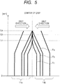
- FIG. 5 is a schematic view illustrating a state in which the fingers 11a and 11b are brought into contact with each other with different grip force Fa, Fb and Fc.
- the strength of the grip force Fa, Fb and Fc is Fa ⁇ Fb ⁇ Fc.
- the position of the contact portions 111a and 111b is a part where the distance from the fixing portions 112a and 112b is La.
- the position of the contact portions 111a and 111b is a part where the distance from the fixing portions 112a and 112b is Lb.
- the position of the contact portions 111a and 111b is a part where the distance from the fixing portions 112a and 112b is Lc.
- the distances La, Lb and Lc from the fixing portions 112a and 112b are Lc ⁇ Lb ⁇ La. In this way, the higher the set grip force, the closer the contact portions 111a and 111b to the fixing portions 112a and 112b.
- FIG. 6 is a graph indicating a relationship between ⁇ F and ⁇ d measured in advance in an experiment in the robot hand 10 with the fingers 11a and 11b having the characteristics described above.
- the movement quantity ⁇ d of the fixing portions 112a and 112b the relationship between the difference ⁇ F from the target grip force F n and the movement quantity ⁇ d changes according to the current strength of the grip force F n-1 as illustrated in FIG. 6 , and the value of ⁇ d to ⁇ F is greater when the current grip force F n-1 is weaker.
- FIG. 7 is a specific example of a grip force adjustment table illustrating a relationship between ⁇ F and ⁇ d in a case in which the grip force is increased from a state that the fingers 11a and 11b are brought into contact with minimum grip force 2N when the grip force F that can be set in the robot hand 10 is 2 to 20 [N].
- the CPU 301 In creating the grip force adjustment table, the CPU 301 first performs grip operation for a plurality of times (n times), in which the fingers 11a and 11b are put into the closed state with the grip force in the entire range from 2 to 20N.
- the adjustment accuracy of the grip force increases with an increase in the number of times of the grip operation with each grip force and with an increase in the number of times of recording the measurement results.
- the grip force is changed by 2N in the measurement results illustrated in the grip force adjustment table of FIG. 7
- the change quantity of the grip force in each grip operation may be set to a smaller quantity (for example, each 0.5N) to execute the grip operation.
- the grip force set at the execution of each grip operation is predetermined grip force in the present embodiment.
- the CPU 301 records, as a measurement result, the output signal from the encoder circuit 18 at the time that the balancing of the reaction force is stopped as the fingers 11a and 11b are brought into contact.
- the CPU 301 subtracts the value of the measurement result with the grip force 2N from the values of the measurement results with each grip force.
- the grip force adjustment table that is a table in which the rigidity of the fingers 11a and 11b is taken into account and indicating the relationship between the grip force and the position of the fingers 11a and 11b comprises the correlation value in the present embodiment.
- the grip force adjustment table illustrated in FIG. 7 is a grip force adjustment table referenced in changing the current grip force of 2N to the target grip force.
- a plurality of grip force adjustment tables corresponding to each grip force set for the transition to the closed state can be stored in advance in the ROM 302.
- the CPU 301 uses the grip force adjustment table corresponding to the current grip force F n-1 among the grip force adjustment tables as illustrated in FIG. 7 to calculate the movement quantity ⁇ d [mm] of the fingers 11a and 11b corresponding to ⁇ F.
- the CPU 301 uses the calculated instruction value d to execute the servo calculation to calculate the motor driving signal as the driving quantity of the motor 12.
- the CPU 301 outputs the calculated motor driving signal to the motor driver 308 and causes the motor driver 308 to drive the motor 12 (S17).
- the CPU 301 uses the calculated instruction value d to execute the servo calculation and outputs the motor driving signal to the motor driver 308 to drive the motor 12 to thereby move the fixing portions 112a and 112b to the position of d [mm].
- the process of step S17 by the hand controlling unit 30 comprises the changing the grip force in the present embodiment.
- the CPU 301 is configured to bring the contact portions 111a and 111b of the fingers 11a and 11b into contact with the work W and substantially fix the contact portions 111a and 111b to the work W.
- the CPU 301 is configured to move the fixing portions 112a and 112b by the instruction value d to thereby control the position of the fingers 11a and 11b.
- the CPU 301 determines whether the output signal from the encoder circuit 18 is within a range of values set based on the instruction value d (S18). In this process, the CPU 301 determines whether the movement of the fingers 11a and 11b is finished based on the output signal from the encoder circuit 18.
- the range of values set based on the instruction value d is determined by values calculated from the output signals that can be output from the encoder circuit 18. In this process, if the CPU 301 determines that the output signal is not within the range of values set based on the instruction value d (No), the CPU 301 repeats the process of step S18.
- step S19 the CPU 301 transmits a signal indicating that the gripping process or the grip adjustment process is finished to the controlling instruction unit 40 (S19).
- the controlling instruction unit 40 receives the signal indicating that the gripping process or the grip adjustment process is finished and proceeds to the following assembly operation.
- the driving quantity of the motor 12 is controlled by using the instruction value d of the position control without using the motor driving current I and the motor rotating speed v at the execution of the grip force adjustment process.
- the motor 12 can be driven to move the fixing portions 112a and 112b to control the position of the fingers 11a and 11b to thereby make an adjustment from the first grip force F n-1 to the second grip force F n . Therefore, the robotics device 1 can use the robot hand controlling method according to the present embodiment to change the grip force by calculating the driving quantity of the motor 12 from the position d of the fingers 11a and 11b when the work W is gripped by the changed grip force. As a result, the robotics device 1 using the robot hand controlling method according to the present embodiment can accurately adjust the grip force from the state that the work W is gripped.
- the robot hand 10 with a simple configuration without a sensor or the like that measures the grip force can execute the gripping process and the grip adjustment process. Therefore, the robot hand controlling method according to the present embodiment can be used to downsize the robot hand 10 in the robotics device 1 and manufacture the robotics device 1 at a low cost.
- the grip force adjustment table is a table of the relationship between the grip force of the fingers 11a and 11b and the position of the fixing portions 112a and 112b in which the rigidity of the fingers 11a and 11b is taken into account in the present embodiment
- the table is not limited to this, and a deformation amount of the work W can also be taken into account.
- the grip force adjustment table is created by measuring the position of the fixing portions 112a and 112b by causing the fingers 11a and 11b in the open state to grip the work W in the entire range of the grip force that can be set. Variations in the dimensional tolerance of the work W also need to be considered in creating the grip force adjustment table of the gripped work W.
- the grip force adjustment table may be created according to the types of the work W.
- the grip force adjustment table in which the deformation amount of the work W is taken into account can be used to easily adjust the grip force in the robot hand controlling method even in gripping of the work W with a low rigidity that is deformed when the fingers 11a and 11b grip the work W.
- the CPU 301 uses the grip force adjustment table to set ⁇ d at the execution of the grip adjustment process in the present embodiment, the process is not limited to this.
- the CPU 301 may assume the fingers 11a and 11b as a cantilever model to calculate ⁇ d from a calculation formula of deflection, for example.
- the CPU 301 may derive a calculation formula for adjusting the grip force that approximates the relationship between ⁇ F and ⁇ d based on data of a plurality of grip force adjustment tables or may store the calculation formula in advance in the ROM 302 to calculate ⁇ d by assigning ⁇ F to the calculation formula.
- steps of creating the grip force adjustment table and setting in advance the relationship between ⁇ F and ⁇ d comprise the setting the correlation value in the present embodiment, and various calculation formulas for adjusting the grip force comprise the correlation value in the present embodiment.
- the calculation of d ⁇ based on the calculation formula for adjusting and converting the grip force is the same even when the deformation amount of the work W is taken into account.
- the calculation formula in which the deformation amount of the work W is taken into account may be derived or stored in advance in the ROM 302 to calculate ⁇ d.
- the CPU 301 may change the PID gain of control in the grip force adjustment process from the PID gain of control in the gripping process.
- An example of changing the PID gain of control in the grip force adjustment process includes setting a higher integral gain to control the position at the target position d against the elasticity of the fingers 11a and 11b.
- the CPU 301 determines whether the fingers 11a and 11b are in the open state or the closed state based on whether the grip force F n-1 is 0 in the process of step S12 in the present embodiment, the method is not limited to this.
- a command of controlling instruction transmitted from the controlling instruction unit 40 may be stored in the RAM 303 every time the command is received, and the CPU 301 may refer to the content of the command to determine whether the fingers 11a and 11b are in the open state or the closed state.
- the CPU 301 of the robotics device 1 receives the output signals output from the encoder circuit 18 in the processes of steps S15 and S18 to determine whether the gripping process or the grip adjustment process is finished in the present embodiment, the process is not limited to this.
- the controlling instruction unit 40 of the robotics device 1 may be configured to determine the end of the gripping process or the grip adjustment process. According to the configuration, the hand controlling unit 30 of the robotics device 1 needs to periodically transmit the output signals, which are output from the encoder circuit 18, to the controlling instruction unit 40 through the communication cable 41.
- the hand controlling unit 30 executes the robot hand controlling program illustrated in FIG. 4 in the present embodiment
- the robot hand controlling program can be recorded in a computer-readable recording medium, and a computer can read and execute the robot hand controlling program.
- the CPU 301 of the hand controlling unit 30 and the instruction value conversion program 304a convert the controlling instructions transmitted from the controlling instruction unit 40 into the parameters necessary for the servo calculation in the robotics device 1 in the present embodiment
- the arrangement is not limited to this.
- the controlling instruction unit 40 of the robotics device 1 may convert the controlling instructions into the parameters necessary for the servo calculation.
- FIG. 8 is a diagram illustrating the robotics device 1 in which the controlling instruction unit 40 converts the controlling instructions into the parameters necessary for the servo calculation.
- the controlling instruction unit 40 includes a CPU 401 that executes various calculation processes for converting the controlling instructions into the parameters necessary for the servo calculation.
- the CPU 401 can execute the processes of steps S11 to S13 and S16 illustrated in FIG. 4 . More specifically, the CPU 401 uses the initial grip conversion table to convert the controlling instructions at the execution of the gripping process and transmits the converted motor driving current I and motor rotating speed v to the CPU 301.
- the CPU 401 further prepares a test grip mode for putting the fingers 11a and 11b into the closed state with a plurality of different instruction grip force.
- the CPU 401 can store, in the RAM 403, the obtained relationship between the instruction grip force and the stop position of the fixing portions 112a and 112b in gripping with the grip force to thereby acquire the grip force adjustment table to execute the grip adjustment process.
- the robotics device 1 can combine a commercially available robot hand and a hand controller with the controlling instruction unit 40 to realize the robot hand controlling method of the present invention.
- the robotics device 1 can also acquire again and update the relationship between ⁇ F and ⁇ d when the relationship between ⁇ F and ⁇ d in the initially acquired grip force adjustment table or in the calculation formula that can calculate ⁇ d from ⁇ F is broken due to a temporal change of the robot hand 10. Therefore, the robotics device 1 can calibrate the relationship between ⁇ F and ⁇ d.
- the robotics device 1 can also acquire the grip force adjustment table or the calculation formula that can calculate ⁇ d from ⁇ F while continuing the assembly operation when the type of the work W is changed.
- the fingers 11a and 11b are a pair of members in a tweezer shape in the present embodiment and the modified example, the arrangement is not limited to this. Any shape and the number of fingers are possible as long as the fingers are elastic and capable of grasping the work W.
- the motor 12 is an AC servo motor including the encoder circuit 18 that is a sensor for detecting the rotation angle in the present embodiment and the modified example
- the arrangement is not limited to this, and any actuator including a sensor capable of controlling the grip force and controlling the position can be used.
- the robot hand 10 includes one motor 12 as an actuator for generating the driving force, the arrangement is not limited to this, and a plurality of actuators may be included for respective fingers.
- the robot hand 10 includes the rack gears 14a and 14b and the pinion gear 15 that are driving force transmission mechanisms in the present embodiment and the modified example, the arrangement is not limited to this.
- the robot hand 10 can be any component that can drive the motor 12 to move the fingers 11a and 11b to grip the work W.
- Embodiment(s) of the present invention can also be realized by a computer of a system or apparatus that reads out and executes computer executable instructions (e.g., one or more programs) recorded on a storage medium (which may also be referred to more fully as a 'non-transitory computer-readable storage medium') to perform the functions of one or more of the above-described embodiment(s) and/or that includes one or more circuits (e.g., application specific integrated circuit (ASIC)) for performing the functions of one or more of the above-described embodiment(s), and by a method performed by the computer of the system or apparatus by, for example, reading out and executing the computer executable instructions from the storage medium to perform the functions of one or more of the above-described embodiment(s) and/or controlling the one or more circuits to perform the functions of one or more of the above-described embodiment(s).
- computer executable instructions e.g., one or more programs
- a storage medium which may also be referred to more fully as
- the computer may comprise one or more processors (e.g., central processing unit (CPU), micro processing unit (MPU)) and may include a network of separate computers or separate processors to read out and execute the computer executable instructions.
- the computer executable instructions may be provided to the computer, for example, from a network or the storage medium.
- the storage medium may include, for example, one or more of a hard disk, a random-access memory (RAM), a read only memory (ROM), a storage of distributed computing systems, an optical disk (such as a compact disc (CD), digital versatile disc (DVD), or Blu-ray Disc (BD)TM), a flash memory device, a memory card, and the like.
- a robot hand controlling method executes calculating a position and changing grip force when the grip force for gripping a work W is to be changed in a state that fingers are gripping the work W with first grip force.
- the hand controlling unit uses a correlation value indicating a relationship between the grip force of the fingers and position of fixing portions, the first grip force, and second grip force that is a target value of the grip force to calculate the position of the fixing portions in gripping the work W with the second grip force.
- the hand controlling unit drives a motor by calculating a driving quantity of the motor necessary for moving the fingers to the calculated position of the fixing portions.
Applications Claiming Priority (1)
| Application Number | Priority Date | Filing Date | Title |
|---|---|---|---|
| JP2015019482A JP6468871B2 (ja) | 2015-02-03 | 2015-02-03 | ロボットハンド制御方法及びロボット装置 |
Publications (2)
| Publication Number | Publication Date |
|---|---|
| EP3053711A1 EP3053711A1 (en) | 2016-08-10 |
| EP3053711B1 true EP3053711B1 (en) | 2018-10-03 |
Family
ID=55272271
Family Applications (1)
| Application Number | Title | Priority Date | Filing Date |
|---|---|---|---|
| EP16153094.4A Active EP3053711B1 (en) | 2015-02-03 | 2016-01-28 | Robot hand controlling method and robotics device |
Country Status (4)
| Country | Link |
|---|---|
| US (1) | US10016893B2 (ja) |
| EP (1) | EP3053711B1 (ja) |
| JP (1) | JP6468871B2 (ja) |
| CN (1) | CN105835056B (ja) |
Families Citing this family (24)
| Publication number | Priority date | Publication date | Assignee | Title |
|---|---|---|---|---|
| JP6468871B2 (ja) * | 2015-02-03 | 2019-02-13 | キヤノン株式会社 | ロボットハンド制御方法及びロボット装置 |
| DE102015214170A1 (de) * | 2015-07-27 | 2017-02-02 | Kuka Roboter Gmbh | Roboter mit einer Kraftmesseinrichtung |
| CN108025407B (zh) * | 2015-09-18 | 2021-04-13 | 索尼公司 | 附接装置、附接方法及手机构 |
| JP6983501B2 (ja) * | 2016-11-10 | 2021-12-17 | キヤノン株式会社 | 把持装置の制御方法、プログラム、記録媒体、把持装置、ロボット装置、および部品の製造方法 |
| FR3062081B1 (fr) * | 2017-01-23 | 2020-02-14 | Interscience | Dispositif de prehension a actionnement lineaire |
| JP6363752B1 (ja) * | 2017-03-13 | 2018-07-25 | 上銀科技股▲フン▼有限公司 | 把持装置 |
| CN110573311B (zh) * | 2017-05-09 | 2023-05-23 | 索尼公司 | 机器人设备和电子设备制造方法 |
| CN107571168B (zh) * | 2017-08-03 | 2018-08-07 | 广东轻工职业技术学院 | 一种夹头装置 |
| DE102017009816B4 (de) * | 2017-10-20 | 2024-02-29 | Kuka Deutschland Gmbh | Ermittlung einer Antriebsreferenzstellung eines Zangenantriebs |
| CN109842345A (zh) * | 2017-11-27 | 2019-06-04 | 深圳市优必选科技有限公司 | 一种驱动舵机的方法及装置 |
| CN108044627B (zh) * | 2017-12-29 | 2020-07-31 | 深圳市越疆科技有限公司 | 抓取位置的检测方法、装置及机械臂 |
| CN108445794B (zh) * | 2018-02-28 | 2021-08-27 | 辽宁科技大学 | 一种感应机器钳夹持控制器系统及控制方法 |
| US11584016B2 (en) * | 2018-04-24 | 2023-02-21 | Fanuc Corporation | Robot controller and system |
| CN109109011B (zh) * | 2018-09-19 | 2021-10-19 | 山东大学 | 一种可调机械手 |
| US11192253B2 (en) * | 2018-10-12 | 2021-12-07 | Toyota Research Institute, Inc. | Systems and methods for conditional robotic teleoperation |
| CN109571526A (zh) * | 2018-12-26 | 2019-04-05 | 深圳市证通电子股份有限公司 | 夹取机及电流检测方法 |
| US10335947B1 (en) | 2019-01-18 | 2019-07-02 | Mujin, Inc. | Robotic system with piece-loss management mechanism |
| DE102019107975B3 (de) * | 2019-03-28 | 2020-08-13 | Franka Emika Gmbh | Einlernen einer Haltekraft für einen Gegenstand in einem robotischen Greifer |
| JP6691993B2 (ja) * | 2019-06-07 | 2020-05-13 | 株式会社荏原製作所 | 基板搬送用移載機及び基板移載方法 |
| CN110723638B (zh) * | 2019-10-29 | 2020-09-29 | 中国科学院合肥物质科学研究院 | 一种用于核环境下大型重载部件的吊装机构 |
| JP2021191382A (ja) * | 2020-06-05 | 2021-12-16 | 国立大学法人 岡山大学 | 穿刺針把持装置及びこの穿刺針把持装置を備えた穿刺ロボット |
| JP2022073193A (ja) * | 2020-10-30 | 2022-05-17 | セイコーエプソン株式会社 | ハンドの駆動方法およびハンド |
| DE102022128993A1 (de) | 2022-11-02 | 2024-05-02 | Schunk Gmbh & Co. Kg Spann- Und Greiftechnik | Greif- oder Spannvorrichtung zum Greifen oder Spannen von Gegenständen in unterschiedlichen Betriebsmodi und Verfahren hierfür |
| CN117718765B (zh) * | 2024-02-07 | 2024-04-30 | 宁波德凯数控机床有限公司 | 一种龙门加工中心工作台 |
Family Cites Families (76)
| Publication number | Priority date | Publication date | Assignee | Title |
|---|---|---|---|---|
| FR2416094A1 (fr) * | 1978-02-01 | 1979-08-31 | Zarudiansky Alain | Dispositif de manipulation a distance |
| DE2823584C2 (de) * | 1978-05-30 | 1983-01-27 | Pfaff Industriemaschinen Gmbh, 6750 Kaiserslautern | Greifvorrichtung für Industrieroboter |
| US4921293A (en) * | 1982-04-02 | 1990-05-01 | The United States Of America As Represented By The Administrator Of The National Aeronautics And Space Administration | Multi-fingered robotic hand |
| FR2582563B1 (fr) * | 1985-05-30 | 1987-07-24 | Centre Nat Rech Scient | Prehenseur tactile pneumatique developpant une force de serrage asservie au poids de l'objet manipule |
| US4715773A (en) * | 1985-06-04 | 1987-12-29 | Clemson University | Method and apparatus for repositioning a mislocated object with a robot hand |
| US4783107A (en) * | 1985-06-04 | 1988-11-08 | Clemson University | Method and apparatus for controlling impact force during rapid robotic acquisition of object |
| US5108140A (en) * | 1988-04-18 | 1992-04-28 | Odetics, Inc. | Reconfigurable end effector |
| JPH0248190A (ja) * | 1988-08-05 | 1990-02-16 | Oki Electric Ind Co Ltd | ロボットハンド装置 |
| US5501498A (en) * | 1988-08-31 | 1996-03-26 | The Trustees Of The University Of Pennsylvania | Methods and apparatus for mechanically intelligent grasping |
| US4957320A (en) * | 1988-08-31 | 1990-09-18 | Trustees Of The University Of Pennsylvania | Methods and apparatus for mechanically intelligent grasping |
| US4980626A (en) * | 1989-08-10 | 1990-12-25 | The United States Of America As Represented By The Administrator Of The National Aeronautics And Space Administration | Method and apparatus for positioning a robotic end effector |
| JP2728182B2 (ja) * | 1990-10-30 | 1998-03-18 | キヤノン株式会社 | ワーク把持装置 |
| US5172951A (en) * | 1990-08-06 | 1992-12-22 | University Of Utah Research Foundation | Robotic grasping apparatus |
| WO1997009153A1 (en) * | 1995-09-08 | 1997-03-13 | Ross-Hime Designs, Inc. | Robotic manipulator |
| US5762390A (en) * | 1996-07-16 | 1998-06-09 | Universite Laval | Underactuated mechanical finger with return actuation |
| US6594552B1 (en) * | 1999-04-07 | 2003-07-15 | Intuitive Surgical, Inc. | Grip strength with tactile feedback for robotic surgery |
| US6517132B2 (en) * | 2000-04-04 | 2003-02-11 | Honda Giken Kogyo Kabushiki Kaisha | Multifinger hand device |
| JP2002178281A (ja) | 2000-12-15 | 2002-06-25 | Kawasaki Heavy Ind Ltd | 把持力制御装置および把持力推定装置 |
| JP3996015B2 (ja) * | 2002-08-09 | 2007-10-24 | 本田技研工業株式会社 | 姿勢認識装置及び自律ロボット |
| JP3702257B2 (ja) * | 2002-08-23 | 2005-10-05 | ファナック株式会社 | ロボットハンドリング装置 |
| US6817641B1 (en) * | 2002-08-30 | 2004-11-16 | Lawrence J. Singleton, Jr. | Robotic arm and hand |
| US7168748B2 (en) * | 2002-09-26 | 2007-01-30 | Barrett Technology, Inc. | Intelligent, self-contained robotic hand |
| US7443115B2 (en) * | 2002-10-29 | 2008-10-28 | Matsushita Electric Industrial Co., Ltd. | Apparatus and method for robot handling control |
| JP4313125B2 (ja) * | 2003-09-12 | 2009-08-12 | 本田技研工業株式会社 | ロボットハンド |
| JP4592276B2 (ja) * | 2003-10-24 | 2010-12-01 | ソニー株式会社 | ロボット装置のためのモーション編集装置及びモーション編集方法、並びにコンピュータ・プログラム |
| JP4621827B2 (ja) * | 2004-03-09 | 2011-01-26 | 財団法人名古屋産業科学研究所 | 光学式触覚センサ、光学式触覚センサを利用したセンシング方法、センシングシステム、物体操作力制御方法、物体操作力制御装置、物体把持力制御装置及びロボットハンド |
| US7795832B2 (en) * | 2004-03-31 | 2010-09-14 | Japan Science And Technology Agency | Robot hand |
| WO2005099417A2 (en) * | 2004-04-12 | 2005-10-27 | Strider Labs, Inc. | System and method for computing grasps for a robotic hand with a palm |
| JP2006102920A (ja) * | 2004-10-08 | 2006-04-20 | Fanuc Ltd | 把握型ハンド |
| US7921741B2 (en) * | 2004-12-15 | 2011-04-12 | Motorola Mobility, Inc. | Electromagnetic testing model of human hand |
| JP4829622B2 (ja) * | 2005-02-17 | 2011-12-07 | キヤノン株式会社 | スイッチング電源、スイッチング電源を備えた電子機器、スイッチング電源を備えた記録装置 |
| US20060293615A1 (en) * | 2005-06-10 | 2006-12-28 | Valero-Cuevas Francisco J | Device and method for quantifying and extracting sensorimotor circuitry |
| JP2007015037A (ja) * | 2005-07-05 | 2007-01-25 | Sony Corp | ロボットのモーション編集装置及びモーション編集方法、コンピュータ・プログラム、並びにロボット装置 |
| JP4418788B2 (ja) * | 2005-10-19 | 2010-02-24 | キヤノン株式会社 | スイッチング電源及び該スイッチング電源を含む電子機器、並びにスイッチング電源の制御方法 |
| JP2007125674A (ja) * | 2005-11-07 | 2007-05-24 | Nisca Corp | マイクロマニピュレータ |
| JP4908020B2 (ja) * | 2006-03-02 | 2012-04-04 | 本田技研工業株式会社 | ハンド制御システム |
| US7650263B2 (en) * | 2006-09-26 | 2010-01-19 | Strider Labs, Inc. | Method for fast computation of optimal contact forces |
| WO2008058061A2 (en) * | 2006-11-03 | 2008-05-15 | President And Fellows Of Harvard College | Robust compliant adaptive grasper and method of manufacturing same |
| JP4890199B2 (ja) * | 2006-11-09 | 2012-03-07 | 本田技研工業株式会社 | ロボットハンドおよびロボット |
| JP4481291B2 (ja) * | 2006-12-01 | 2010-06-16 | 本田技研工業株式会社 | ロボット、ならびにその制御方法および制御プログラム |
| JP2009066685A (ja) * | 2007-09-11 | 2009-04-02 | Sony Corp | ロボット装置及びロボット装置の制御方法 |
| JP5187552B2 (ja) * | 2007-09-13 | 2013-04-24 | ソニー株式会社 | 制御装置および方法、プログラム並びに記録媒体 |
| US20090306825A1 (en) * | 2008-04-21 | 2009-12-10 | Ying Li | Manipulation system and method |
| JP5072695B2 (ja) * | 2008-04-22 | 2012-11-14 | 株式会社ハーモニック・ドライブ・システムズ | ロボットハンドおよび指機構 |
| KR101479232B1 (ko) * | 2008-05-13 | 2015-01-06 | 삼성전자 주식회사 | 로봇과 로봇 핸드, 로봇 핸드의 제어 방법 |
| KR100997140B1 (ko) * | 2008-07-16 | 2010-11-30 | 삼성전자주식회사 | 인간형 로봇 |
| KR101549818B1 (ko) * | 2008-12-02 | 2015-09-07 | 삼성전자 주식회사 | 로봇 핸드 및 그 제어방법 |
| US8346393B2 (en) * | 2008-12-18 | 2013-01-01 | Samsung Electronics Co., Ltd. | Control apparatus of multi-finger hand and grasping method using the same |
| JP5458274B2 (ja) * | 2009-02-09 | 2014-04-02 | 本田技研工業株式会社 | 把持位置計算装置及び把持位置計算方法 |
| US8364314B2 (en) * | 2009-04-30 | 2013-01-29 | GM Global Technology Operations LLC | Method and apparatus for automatic control of a humanoid robot |
| US8504198B2 (en) * | 2009-05-14 | 2013-08-06 | Honda Motor Co., Ltd. | Robot hand and control system, control method and control program for the same |
| JP5335551B2 (ja) * | 2009-05-14 | 2013-11-06 | 本田技研工業株式会社 | ロボットハンドならびにその制御システム、制御方法および制御プログラム |
| US8280837B2 (en) * | 2009-05-28 | 2012-10-02 | GM Global Technology Operations LLC | Contact state estimation for multi-finger robot hands using particle filters |
| US8511964B2 (en) * | 2009-09-22 | 2013-08-20 | GM Global Technology Operations LLC | Humanoid robot |
| DE102009058607A1 (de) * | 2009-12-17 | 2011-06-22 | KUKA Laboratories GmbH, 86165 | Verfahren und Vorrichtung zum Steuern eines Manipulators |
| JP2011200943A (ja) * | 2010-03-24 | 2011-10-13 | Canon Inc | 力制御ロボット |
| JP5993539B2 (ja) * | 2011-01-06 | 2016-09-14 | セイコーエプソン株式会社 | ロボットハンド及びロボット |
| CN103347662A (zh) * | 2011-01-27 | 2013-10-09 | 松下电器产业株式会社 | 机器人手臂的控制装置及控制方法、机器人、机器人手臂控制程序以及集成电路 |
| JP5810582B2 (ja) * | 2011-03-29 | 2015-11-11 | セイコーエプソン株式会社 | ロボットの制御方法、及びロボット |
| JP5588392B2 (ja) * | 2011-04-27 | 2014-09-10 | 株式会社日立製作所 | マニプレータ装置 |
| JP5834478B2 (ja) * | 2011-05-10 | 2015-12-24 | セイコーエプソン株式会社 | ロボット |
| US8534729B2 (en) * | 2011-08-04 | 2013-09-17 | Harris Corporation | High-force robotic gripper |
| US9067319B2 (en) * | 2011-08-11 | 2015-06-30 | GM Global Technology Operations LLC | Fast grasp contact computation for a serial robot |
| WO2013069118A1 (ja) * | 2011-11-09 | 2013-05-16 | 株式会社安川電機 | ロボットハンド及びロボット |
| KR101941844B1 (ko) * | 2012-01-10 | 2019-04-11 | 삼성전자주식회사 | 로봇 및 그 제어방법 |
| JP5983080B2 (ja) | 2012-06-20 | 2016-08-31 | セイコーエプソン株式会社 | ロボットハンド、ロボット、および把持機構 |
| CN102772865B (zh) | 2012-08-02 | 2014-09-10 | 北京机械设备研究所 | 一种单向喷洒式无杀伤破片灭火弹 |
| JP2014046449A (ja) * | 2012-09-04 | 2014-03-17 | Canon Inc | ロボットハンド制御方法、ロボットハンド制御装置及びロボット装置 |
| US8833827B2 (en) * | 2012-10-09 | 2014-09-16 | Willow Garage, Inc. | Kinetic and dimensional optimization for a tendon-driven gripper |
| JP2014108466A (ja) | 2012-11-30 | 2014-06-12 | Fanuc Ltd | 力センサ付き電動ハンド |
| US9399291B2 (en) * | 2012-12-07 | 2016-07-26 | GM Global Technology Operations LLC | Planning a grasp, for use by a robotic grasper to pick up a complex object, based on object, grasper, and grasper approach data |
| JP6358463B2 (ja) * | 2013-11-13 | 2018-07-18 | パナソニックIpマネジメント株式会社 | マスタースレーブ装置用マスター装置及びその制御方法、及び、マスタースレーブ装置 |
| US9259844B2 (en) * | 2014-02-12 | 2016-02-16 | General Electric Company | Vision-guided electromagnetic robotic system |
| US9321176B1 (en) * | 2014-04-01 | 2016-04-26 | University Of South Florida | Systems and methods for planning a robot grasp based upon a demonstrated grasp |
| CN204076288U (zh) | 2014-09-02 | 2015-01-07 | 安川首钢机器人有限公司 | 一种夹紧装置和机器人系统 |
| JP6468871B2 (ja) * | 2015-02-03 | 2019-02-13 | キヤノン株式会社 | ロボットハンド制御方法及びロボット装置 |
-
2015
- 2015-02-03 JP JP2015019482A patent/JP6468871B2/ja active Active
-
2016
- 2016-01-20 US US15/002,394 patent/US10016893B2/en active Active
- 2016-01-28 EP EP16153094.4A patent/EP3053711B1/en active Active
- 2016-01-29 CN CN201610063959.9A patent/CN105835056B/zh active Active
Non-Patent Citations (1)
| Title |
|---|
| None * |
Also Published As
| Publication number | Publication date |
|---|---|
| US20160221188A1 (en) | 2016-08-04 |
| CN105835056B (zh) | 2019-04-16 |
| EP3053711A1 (en) | 2016-08-10 |
| JP6468871B2 (ja) | 2019-02-13 |
| JP2016140956A (ja) | 2016-08-08 |
| US10016893B2 (en) | 2018-07-10 |
| CN105835056A (zh) | 2016-08-10 |
Similar Documents
| Publication | Publication Date | Title |
|---|---|---|
| EP3053711B1 (en) | Robot hand controlling method and robotics device | |
| US10108177B2 (en) | Control parameter adjustment device | |
| US10144132B2 (en) | Robot controlling method, robot apparatus, program and recording medium | |
| CN110076773B (zh) | 机器人设备、制造物品的方法及电机驱动设备 | |
| JP4202365B2 (ja) | 力制御装置 | |
| US10162912B2 (en) | Friction identification method and friction identification device | |
| Lehmann et al. | Robot joint modeling and parameter identification using the clamping method | |
| JP5657633B2 (ja) | 移動体が反転するときの位置誤差を補正するサーボ制御装置 | |
| JP2016168650A (ja) | ロボット装置、ロボット制御方法、プログラム及び記録媒体 | |
| JP2014046449A (ja) | ロボットハンド制御方法、ロボットハンド制御装置及びロボット装置 | |
| US20230405817A1 (en) | Method and computing system for estimating parameter for robot operation | |
| CN107438502B (zh) | 通过触摸来控制工业机器人的方法 | |
| Madsen et al. | Model-based on-line estimation of time-varying nonlinear joint stiffness on an e-series universal robots manipulator | |
| CN108242906B (zh) | 电机控制系统 | |
| JP7034383B2 (ja) | サーボ制御装置 | |
| US11491666B2 (en) | Control system, control method, and control program | |
| JP6632214B2 (ja) | 制御方法、ロボットハンド、ロボット装置、製造方法、ロボットハンド制御プログラム及び記録媒体 | |
| JP2018069381A (ja) | 把持装置の制御方法、把持装置、ロボット装置、および部品の製造方法 | |
| JP2016005296A (ja) | モータ駆動装置の制御方法、モータ駆動装置及びロボット装置 | |
| Yu et al. | Dynamical model and experimental identification of a cable-driven finger joint for surgical robot | |
| JP2011015550A (ja) | 機械装置の制御装置及び機械装置の特性同定方法 | |
| Yamada et al. | Precise external torque estimation for two-inertia system considering modeling errors | |
| JP7005127B2 (ja) | 制御システム | |
| WO2018079107A1 (ja) | 外力検出方法 | |
| JP2021030341A (ja) | ロボットハンド |
Legal Events
| Date | Code | Title | Description |
|---|---|---|---|
| PUAI | Public reference made under article 153(3) epc to a published international application that has entered the european phase |
Free format text: ORIGINAL CODE: 0009012 |
|
| AK | Designated contracting states |
Kind code of ref document: A1 Designated state(s): AL AT BE BG CH CY CZ DE DK EE ES FI FR GB GR HR HU IE IS IT LI LT LU LV MC MK MT NL NO PL PT RO RS SE SI SK SM TR |
|
| AX | Request for extension of the european patent |
Extension state: BA ME |
|
| STAA | Information on the status of an ep patent application or granted ep patent |
Free format text: STATUS: REQUEST FOR EXAMINATION WAS MADE |
|
| 17P | Request for examination filed |
Effective date: 20170210 |
|
| RBV | Designated contracting states (corrected) |
Designated state(s): AL AT BE BG CH CY CZ DE DK EE ES FI FR GB GR HR HU IE IS IT LI LT LU LV MC MK MT NL NO PL PT RO RS SE SI SK SM TR |
|
| GRAP | Despatch of communication of intention to grant a patent |
Free format text: ORIGINAL CODE: EPIDOSNIGR1 |
|
| STAA | Information on the status of an ep patent application or granted ep patent |
Free format text: STATUS: GRANT OF PATENT IS INTENDED |
|
| INTG | Intention to grant announced |
Effective date: 20171212 |
|
| RIN1 | Information on inventor provided before grant (corrected) |
Inventor name: NAGAI, MASAYUKI |
|
| GRAJ | Information related to disapproval of communication of intention to grant by the applicant or resumption of examination proceedings by the epo deleted |
Free format text: ORIGINAL CODE: EPIDOSDIGR1 |
|
| STAA | Information on the status of an ep patent application or granted ep patent |
Free format text: STATUS: REQUEST FOR EXAMINATION WAS MADE |
|
| GRAP | Despatch of communication of intention to grant a patent |
Free format text: ORIGINAL CODE: EPIDOSNIGR1 |
|
| STAA | Information on the status of an ep patent application or granted ep patent |
Free format text: STATUS: GRANT OF PATENT IS INTENDED |
|
| INTC | Intention to grant announced (deleted) | ||
| INTG | Intention to grant announced |
Effective date: 20180504 |
|
| GRAS | Grant fee paid |
Free format text: ORIGINAL CODE: EPIDOSNIGR3 |
|
| GRAA | (expected) grant |
Free format text: ORIGINAL CODE: 0009210 |
|
| STAA | Information on the status of an ep patent application or granted ep patent |
Free format text: STATUS: THE PATENT HAS BEEN GRANTED |
|
| AK | Designated contracting states |
Kind code of ref document: B1 Designated state(s): AL AT BE BG CH CY CZ DE DK EE ES FI FR GB GR HR HU IE IS IT LI LT LU LV MC MK MT NL NO PL PT RO RS SE SI SK SM TR |
|
| REG | Reference to a national code |
Ref country code: GB Ref legal event code: FG4D |
|
| REG | Reference to a national code |
Ref country code: CH Ref legal event code: EP Ref country code: AT Ref legal event code: REF Ref document number: 1048111 Country of ref document: AT Kind code of ref document: T Effective date: 20181015 |
|
| REG | Reference to a national code |
Ref country code: IE Ref legal event code: FG4D Ref country code: DE Ref legal event code: R096 Ref document number: 602016006115 Country of ref document: DE |
|
| REG | Reference to a national code |
Ref country code: NL Ref legal event code: MP Effective date: 20181003 |
|
| REG | Reference to a national code |
Ref country code: LT Ref legal event code: MG4D |
|
| REG | Reference to a national code |
Ref country code: AT Ref legal event code: MK05 Ref document number: 1048111 Country of ref document: AT Kind code of ref document: T Effective date: 20181003 |
|
| PG25 | Lapsed in a contracting state [announced via postgrant information from national office to epo] |
Ref country code: NL Free format text: LAPSE BECAUSE OF FAILURE TO SUBMIT A TRANSLATION OF THE DESCRIPTION OR TO PAY THE FEE WITHIN THE PRESCRIBED TIME-LIMIT Effective date: 20181003 |
|
| PG25 | Lapsed in a contracting state [announced via postgrant information from national office to epo] |
Ref country code: IS Free format text: LAPSE BECAUSE OF FAILURE TO SUBMIT A TRANSLATION OF THE DESCRIPTION OR TO PAY THE FEE WITHIN THE PRESCRIBED TIME-LIMIT Effective date: 20190203 Ref country code: LT Free format text: LAPSE BECAUSE OF FAILURE TO SUBMIT A TRANSLATION OF THE DESCRIPTION OR TO PAY THE FEE WITHIN THE PRESCRIBED TIME-LIMIT Effective date: 20181003 Ref country code: PL Free format text: LAPSE BECAUSE OF FAILURE TO SUBMIT A TRANSLATION OF THE DESCRIPTION OR TO PAY THE FEE WITHIN THE PRESCRIBED TIME-LIMIT Effective date: 20181003 Ref country code: BG Free format text: LAPSE BECAUSE OF FAILURE TO SUBMIT A TRANSLATION OF THE DESCRIPTION OR TO PAY THE FEE WITHIN THE PRESCRIBED TIME-LIMIT Effective date: 20190103 Ref country code: NO Free format text: LAPSE BECAUSE OF FAILURE TO SUBMIT A TRANSLATION OF THE DESCRIPTION OR TO PAY THE FEE WITHIN THE PRESCRIBED TIME-LIMIT Effective date: 20190103 Ref country code: CZ Free format text: LAPSE BECAUSE OF FAILURE TO SUBMIT A TRANSLATION OF THE DESCRIPTION OR TO PAY THE FEE WITHIN THE PRESCRIBED TIME-LIMIT Effective date: 20181003 Ref country code: ES Free format text: LAPSE BECAUSE OF FAILURE TO SUBMIT A TRANSLATION OF THE DESCRIPTION OR TO PAY THE FEE WITHIN THE PRESCRIBED TIME-LIMIT Effective date: 20181003 Ref country code: LV Free format text: LAPSE BECAUSE OF FAILURE TO SUBMIT A TRANSLATION OF THE DESCRIPTION OR TO PAY THE FEE WITHIN THE PRESCRIBED TIME-LIMIT Effective date: 20181003 Ref country code: HR Free format text: LAPSE BECAUSE OF FAILURE TO SUBMIT A TRANSLATION OF THE DESCRIPTION OR TO PAY THE FEE WITHIN THE PRESCRIBED TIME-LIMIT Effective date: 20181003 Ref country code: AT Free format text: LAPSE BECAUSE OF FAILURE TO SUBMIT A TRANSLATION OF THE DESCRIPTION OR TO PAY THE FEE WITHIN THE PRESCRIBED TIME-LIMIT Effective date: 20181003 Ref country code: FI Free format text: LAPSE BECAUSE OF FAILURE TO SUBMIT A TRANSLATION OF THE DESCRIPTION OR TO PAY THE FEE WITHIN THE PRESCRIBED TIME-LIMIT Effective date: 20181003 |
|
| PG25 | Lapsed in a contracting state [announced via postgrant information from national office to epo] |
Ref country code: PT Free format text: LAPSE BECAUSE OF FAILURE TO SUBMIT A TRANSLATION OF THE DESCRIPTION OR TO PAY THE FEE WITHIN THE PRESCRIBED TIME-LIMIT Effective date: 20190203 Ref country code: SE Free format text: LAPSE BECAUSE OF FAILURE TO SUBMIT A TRANSLATION OF THE DESCRIPTION OR TO PAY THE FEE WITHIN THE PRESCRIBED TIME-LIMIT Effective date: 20181003 Ref country code: AL Free format text: LAPSE BECAUSE OF FAILURE TO SUBMIT A TRANSLATION OF THE DESCRIPTION OR TO PAY THE FEE WITHIN THE PRESCRIBED TIME-LIMIT Effective date: 20181003 Ref country code: GR Free format text: LAPSE BECAUSE OF FAILURE TO SUBMIT A TRANSLATION OF THE DESCRIPTION OR TO PAY THE FEE WITHIN THE PRESCRIBED TIME-LIMIT Effective date: 20190104 Ref country code: RS Free format text: LAPSE BECAUSE OF FAILURE TO SUBMIT A TRANSLATION OF THE DESCRIPTION OR TO PAY THE FEE WITHIN THE PRESCRIBED TIME-LIMIT Effective date: 20181003 |
|
| REG | Reference to a national code |
Ref country code: DE Ref legal event code: R097 Ref document number: 602016006115 Country of ref document: DE |
|
| PG25 | Lapsed in a contracting state [announced via postgrant information from national office to epo] |
Ref country code: IT Free format text: LAPSE BECAUSE OF FAILURE TO SUBMIT A TRANSLATION OF THE DESCRIPTION OR TO PAY THE FEE WITHIN THE PRESCRIBED TIME-LIMIT Effective date: 20181003 Ref country code: DK Free format text: LAPSE BECAUSE OF FAILURE TO SUBMIT A TRANSLATION OF THE DESCRIPTION OR TO PAY THE FEE WITHIN THE PRESCRIBED TIME-LIMIT Effective date: 20181003 |
|
| PLBE | No opposition filed within time limit |
Free format text: ORIGINAL CODE: 0009261 |
|
| STAA | Information on the status of an ep patent application or granted ep patent |
Free format text: STATUS: NO OPPOSITION FILED WITHIN TIME LIMIT |
|
| PG25 | Lapsed in a contracting state [announced via postgrant information from national office to epo] |
Ref country code: EE Free format text: LAPSE BECAUSE OF FAILURE TO SUBMIT A TRANSLATION OF THE DESCRIPTION OR TO PAY THE FEE WITHIN THE PRESCRIBED TIME-LIMIT Effective date: 20181003 Ref country code: RO Free format text: LAPSE BECAUSE OF FAILURE TO SUBMIT A TRANSLATION OF THE DESCRIPTION OR TO PAY THE FEE WITHIN THE PRESCRIBED TIME-LIMIT Effective date: 20181003 Ref country code: SK Free format text: LAPSE BECAUSE OF FAILURE TO SUBMIT A TRANSLATION OF THE DESCRIPTION OR TO PAY THE FEE WITHIN THE PRESCRIBED TIME-LIMIT Effective date: 20181003 Ref country code: MC Free format text: LAPSE BECAUSE OF FAILURE TO SUBMIT A TRANSLATION OF THE DESCRIPTION OR TO PAY THE FEE WITHIN THE PRESCRIBED TIME-LIMIT Effective date: 20181003 Ref country code: SM Free format text: LAPSE BECAUSE OF FAILURE TO SUBMIT A TRANSLATION OF THE DESCRIPTION OR TO PAY THE FEE WITHIN THE PRESCRIBED TIME-LIMIT Effective date: 20181003 |
|
| REG | Reference to a national code |
Ref country code: CH Ref legal event code: PL |
|
| 26N | No opposition filed |
Effective date: 20190704 |
|
| PG25 | Lapsed in a contracting state [announced via postgrant information from national office to epo] |
Ref country code: LU Free format text: LAPSE BECAUSE OF NON-PAYMENT OF DUE FEES Effective date: 20190128 |
|
| REG | Reference to a national code |
Ref country code: BE Ref legal event code: MM Effective date: 20190131 |
|
| REG | Reference to a national code |
Ref country code: IE Ref legal event code: MM4A |
|
| PG25 | Lapsed in a contracting state [announced via postgrant information from national office to epo] |
Ref country code: FR Free format text: LAPSE BECAUSE OF NON-PAYMENT OF DUE FEES Effective date: 20190131 Ref country code: SI Free format text: LAPSE BECAUSE OF FAILURE TO SUBMIT A TRANSLATION OF THE DESCRIPTION OR TO PAY THE FEE WITHIN THE PRESCRIBED TIME-LIMIT Effective date: 20181003 |
|
| PG25 | Lapsed in a contracting state [announced via postgrant information from national office to epo] |
Ref country code: BE Free format text: LAPSE BECAUSE OF NON-PAYMENT OF DUE FEES Effective date: 20190131 |
|
| PG25 | Lapsed in a contracting state [announced via postgrant information from national office to epo] |
Ref country code: CH Free format text: LAPSE BECAUSE OF NON-PAYMENT OF DUE FEES Effective date: 20190131 Ref country code: LI Free format text: LAPSE BECAUSE OF NON-PAYMENT OF DUE FEES Effective date: 20190131 |
|
| PG25 | Lapsed in a contracting state [announced via postgrant information from national office to epo] |
Ref country code: IE Free format text: LAPSE BECAUSE OF NON-PAYMENT OF DUE FEES Effective date: 20190128 |
|
| PG25 | Lapsed in a contracting state [announced via postgrant information from national office to epo] |
Ref country code: TR Free format text: LAPSE BECAUSE OF FAILURE TO SUBMIT A TRANSLATION OF THE DESCRIPTION OR TO PAY THE FEE WITHIN THE PRESCRIBED TIME-LIMIT Effective date: 20181003 |
|
| PG25 | Lapsed in a contracting state [announced via postgrant information from national office to epo] |
Ref country code: MT Free format text: LAPSE BECAUSE OF NON-PAYMENT OF DUE FEES Effective date: 20190128 |
|
| GBPC | Gb: european patent ceased through non-payment of renewal fee |
Effective date: 20200128 |
|
| PG25 | Lapsed in a contracting state [announced via postgrant information from national office to epo] |
Ref country code: GB Free format text: LAPSE BECAUSE OF NON-PAYMENT OF DUE FEES Effective date: 20200128 |
|
| PG25 | Lapsed in a contracting state [announced via postgrant information from national office to epo] |
Ref country code: CY Free format text: LAPSE BECAUSE OF FAILURE TO SUBMIT A TRANSLATION OF THE DESCRIPTION OR TO PAY THE FEE WITHIN THE PRESCRIBED TIME-LIMIT Effective date: 20181003 |
|
| PG25 | Lapsed in a contracting state [announced via postgrant information from national office to epo] |
Ref country code: HU Free format text: LAPSE BECAUSE OF FAILURE TO SUBMIT A TRANSLATION OF THE DESCRIPTION OR TO PAY THE FEE WITHIN THE PRESCRIBED TIME-LIMIT; INVALID AB INITIO Effective date: 20160128 |
|
| PG25 | Lapsed in a contracting state [announced via postgrant information from national office to epo] |
Ref country code: MK Free format text: LAPSE BECAUSE OF FAILURE TO SUBMIT A TRANSLATION OF THE DESCRIPTION OR TO PAY THE FEE WITHIN THE PRESCRIBED TIME-LIMIT Effective date: 20181003 |
|
| PGFP | Annual fee paid to national office [announced via postgrant information from national office to epo] |
Ref country code: DE Payment date: 20231219 Year of fee payment: 9 |