EP3045978A2 - Fixiervorrichtung und bilderzeugungsvorrichtung - Google Patents
Fixiervorrichtung und bilderzeugungsvorrichtung Download PDFInfo
- Publication number
- EP3045978A2 EP3045978A2 EP16150330.5A EP16150330A EP3045978A2 EP 3045978 A2 EP3045978 A2 EP 3045978A2 EP 16150330 A EP16150330 A EP 16150330A EP 3045978 A2 EP3045978 A2 EP 3045978A2
- Authority
- EP
- European Patent Office
- Prior art keywords
- fixing
- rotator
- roller
- oil
- recording medium
- Prior art date
- Legal status (The legal status is an assumption and is not a legal conclusion. Google has not performed a legal analysis and makes no representation as to the accuracy of the status listed.)
- Granted
Links
Images


Classifications
-
- G—PHYSICS
- G03—PHOTOGRAPHY; CINEMATOGRAPHY; ANALOGOUS TECHNIQUES USING WAVES OTHER THAN OPTICAL WAVES; ELECTROGRAPHY; HOLOGRAPHY
- G03G—ELECTROGRAPHY; ELECTROPHOTOGRAPHY; MAGNETOGRAPHY
- G03G15/00—Apparatus for electrographic processes using a charge pattern
- G03G15/20—Apparatus for electrographic processes using a charge pattern for fixing, e.g. by using heat
- G03G15/2003—Apparatus for electrographic processes using a charge pattern for fixing, e.g. by using heat using heat
- G03G15/2014—Apparatus for electrographic processes using a charge pattern for fixing, e.g. by using heat using heat using contact heat
- G03G15/2017—Structural details of the fixing unit in general, e.g. cooling means, heat shielding means
- G03G15/2025—Structural details of the fixing unit in general, e.g. cooling means, heat shielding means with special means for lubricating and/or cleaning the fixing unit, e.g. applying offset preventing fluid
Definitions
- Exemplary aspects of the present invention relate to a fixing device and an image forming apparatus incorporating the fixing device.
- Contemporary image forming apparatuses such as copiers, printers, facsimile machines, or multifunction peripherals having two or more copying, printing, and facsimile functions are expected to improve energy saving efficiency, accelerate operation speed, and enhance image quality.
- thermal efficiency of a fixing device used in the image forming apparatus needs to be improved, and heat of various rollers in the fixing device needs to be controlled with precision to meet such recent market demands.
- the image forming apparatus which employs an image transfer method or a direct method, performs an image forming process to form an unfixed toner image on a recording medium (also referred to as a recording material or paper) such as a recording material sheet, printing paper, photosensitized paper, or electrostatic recording paper.
- a recording medium also referred to as a recording material or paper
- the image forming process includes electrophotographic recording, electrostatic recording, and magnetic recording.
- a fixing device that employs a contact heating method is widely used to fix the unfixed toner image on the recording medium.
- the contact heating method includes a heating roller method, a belt fixing method, a film heating method, and an electromagnetic induction method.
- the fixing device employing the heating roller method includes a fixing roller and a pressing roller as a rotation roller pair as a basic configuration.
- the fixing roller includes a heat source such as a halogen lamp, the temperature of which is adjusted to a predetermined temperature.
- the pressing roller is pressed by the fixing roller.
- a recording medium is conveyed to a contact portion called a fixing nip (also referred to as a nip portion) between the rotation roller pair, so that an unfixed toner image is fixed with heat and pressure applied by the fixing roller and the pressing roller.
- the fixing device employing the belt fixing method includes a fixing roller disposed opposite a pressing roller, and an endless fixing belt (a fixing rotator) looped around the fixing roller and a heating roller.
- a fixing nip formed by contacting the pressing roller and the fixing belt heat from the heating roller is applied to a recording medium via the fixing belt, and an unfixed toner image is pressed to the recording medium to fix the unfixed toner image on the recording medium.
- the phrase "generation of a higher value-added output matter by using the transparent toner” includes a case where an entire area of an image has uniform glossiness.
- An electrophotographic apparatus without a transparent toner barely outputs an image having uniform glossiness since a toner does not adhere to a blank portion of the image. Consequently, surface glossiness of paper as a recording medium is output as is.
- a difference in glossiness due to a difference in toner amount adhering to paper is generated between a half-tone image to which a toner adheres in a dot manner and a solid image to which more toner adheres.
- the phrase "generation of a higher value-added output matter by using the white toner” includes a case where white color can be output on colored paper or metallic paper such as hologram.
- white is expressed by a ground color (white) of the paper.
- white cannot be expressed.
- a special color toner image is sequentially formed on a conventional full color toner image (with cyan, magenta, yellow, and back toners), and both of the toner images are fixed at the same time.
- a toner adhesion amount with respect to paper is greater than that for formation of the conventional full color toner image, and thus adherents (e.g., a toner additive component such as toner wax and silica) to a surface of a fixing rotator are generated by the toners.
- JP-2011-175067-A discloses a technique by which a sliding member for sliding on a surface of a fixing rotator recovers local plastic deformation of the fixing rotator.
- the local plastic deformation is caused by stains on the surface of the fixing rotator or burrs on both ends of a recording material, the burrs being generated when the recording material is cut
- JP-2006-259341-A discloses a technique for preventing generation of streaks when an image is formed. According to the technique, a rotary cleaning body contacts a surface of a fixing rotator to remove paper dust accumulated on the fixing rotator surface. This prevents generation of the streaks.
- JP-2002-318482-A and JP-2006-251722-A discloses a method by which only a full color toner image is formed and once fixed on paper, and then a special color toner image is formed on the paper. Subsequently, the special color toner image formed on the paper with the full color image is fixed again.
- JP-2011-175067-A and JP-2006-259341-A a function of removing adherence wax and toner wax from the fixing rotator is not provided. Moreover, a function of determining a distance for which paper passes a fixing device, or a function of automatically executing an operation according to a cumulative amount of toner having passed the fixing device is not provided. Consequently, a failure caused by the wax and the toner wax adhering to the fixing rotator cannot be prevented.
- the special color toner image is formed on the paper with the full color toner image which has been formed and once fixed, and the special toner color image formed on the paper is fixed again.
- the paper is output from an image forming apparatus at a speed decelerated by 50 % or more. This markedly lowers productivity.
- the paper with only the full color toner image is pre-output, a user needs to perform an operation for placing the special color toner on the paper again.
- the present invention has been made in view of these problems, and is to provide a fixing device capable of not only preventing a failure associated with adherence or attachment of foreign substances to a fixing rotator or a pressure rotator due to aging, but also suppressing a winding jam occurrence without lowering output image quality and productivity.
- an improved fixing device that fixes a toner image on a recording medium with heat.
- the fixing device includes a fixing rotator, a pressing rotator, an oil applicator, a first adjuster, a surface modifier, a second adjuster, and a processor.
- the fixing rotator contacts the recording medium bearing the toner image, and the pressing rotator forms a fixing nip with the fixing rotator.
- the oil applicator, impregnated with oil is pressed against at least one of applied members of the fixing rotator and the pressing rotator.
- the first adjuster adjusts contact and separation of the oil applicator with respect to the applied member.
- the surface modifier contacts the fixing rotator to modify a surface of the fixing rotator.
- the second adjuster adjusts contact and separation of the surface modifier with respect to the fixing rotator.
- the processor allows the surface modifier to contact the fixing rotator to modify the surface of the fixing rotator after the oil applicator contacts the applied member, and the oil applicator to separate from the applied member after the surface modifier is separated from the fixing rotator.
- an improved fixing device that fixes a toner image on a recording medium with heat.
- the fixing device includes a fixing rotator, a pressing rotator, an oil application surface modifier, and adjuster.
- the fixing rotator contacts the recording medium bearing the toner image, and the pressing rotator forms a fixing nip with the fixing rotator.
- the oil application surface modifier impregnated with oil, is pressed against at least one of applied members of the fixing rotator and the pressing rotator, and modifies a surface of the applied member.
- the adjuster adjusts contact and separation of the oil application surface modifier with respect to the applied member.
- an improved fixing device that fixes a toner image on a recording medium with heat.
- the fixing device includes a fixing rotator, a pressing rotator, a cleaner, a lubricant applicator, and a processor.
- the fixing rotator contacts the recording medium bearing the toner image, and the pressing rotator forms a fixing nip with the fixing rotator.
- the cleaner is pressed against at least one of applied members of the fixing rotator and the pressing rotator to clean the applied member.
- the lubricant applicator applies lubricant to the cleaner or the applied member. If the recording medium is stuck in the fixing nip, the processor allows the lubricant applicator to apply the lubricant to the cleaner or the applied member at recovery.
- a failure associated with attachment or adhesion of foreign substances to a fixing rotator or a pressing rotator due to aging can be prevented, and a winding jam can be suppressed without lowering output image quality and productivity.
- FIGs. 1 through 10 exemplary embodiments of the present invention are described with reference to FIGs. 1 through 10 .
- a configuration of a fixing device 20 and control performed by a processor 10 according to an exemplary embodiment of the present invention are described with reference to FIG. 1 .
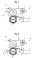
- FIG. 1 In the schematic sectional view of FIG. 1 , one example of the fixing device 20 in an axial direction of a fixing roller 23 is illustrated.
- the processor 10 for the fixing device 20 is disposed inside an image forming apparatus 1 that will described with reference to FIG. 10 .
- the processor 10 comprehensively controls each device of the image forming apparatus 1 including the fixing device 20.
- the fixing device 20 may include a fixing processor 20' to control the fixing device 20 instead of the processor 10.
- the fixing device 20 includes a fixing belt 22 as a fixing rotator to be heated by a heater 37, and a pressing roller 27 as pressing rotator.
- the pressing roller 27 can press the fixing belt 22 at least one location to form a fixing nip with the fixing belt 22.
- the fixing device 20 conveys a recording medium 25 bearing an unfixed toner image 24 to the fixing nip, thereby fixing the unfixed toner image 24 to the recording medium 25.
- the recording medium 25 is guided by a conveyance belt 28 and a guide plate 26 to the fixing nip.
- the fixing device 20 includes a fixing rotator surface modifier 40 and an oil applicator 29.
- the fixing rotator surface modifier 40 is pressed against the fixing belt 22 to modify a surface of the fixing belt 22, whereas the oil applicator 29 is pressed against at least one of the fixing belt 22 and the pressing roller 27 to apply oil.
- the fixing rotator surface modifier 40 is capable of contacting and separating from the fixing belt 22 according to a cumulative amount of time for which the recording medium 25 passes the fixing nip or a cumulative amount of toner adhering to the recording medium 25.
- the oil applicator 29 is capable of contacting and separating from an applied member to which oil is applied.
- the oil applicator 29 contacts and separates from the applied member according to a type and a thickness of the recording medium 25 and a cumulative amount of toner adhering to the recording medium 25 passing the fixing nip.
- the fixing device 20 according to the present exemplary embodiment is described in detail below.
- the fixing device 20 includes a heating roller 21, the fixing roller 23, the fixing belt 22 looped around the heating roller 21 and the fixing roller 23, and the pressing roller 27 that presses the fixing roller 23 to form the fixing nip with the fixing roller 23.
- the heating roller 21 includes the heater 37 as a heat source
- the pressing roller 27 includes a heater 38 as a heat source.
- the fixing device 20 fixes the unfixed toner image on the recording medium 25 with heat and pressure when the recording medium 25 bearing the unfixed toner image 24 passes through the fixing nip between the fixing belt 22 and the pressing roller 27.
- the fixing nip is formed by contacting the fixing roller 23 and the pressing roller 27 against each other.
- Each of the heating roller 21, the fixing roller 23, and the pressing roller 27 is rotatably supported in a longitudinal direction of a casing (not illustrated) of the fixing device 20, and a drive unit (not illustrated) of each of the rollers is supported by the casing.
- a leading end of the recording medium 25 is separated from the fixing nip by a separation plate (not illustrated) disposed near the fixing roller 23 or a separation plate (not illustrated) disposed near the pressing roller 27, and then proceeds to a next process.
- the separation plates as separators respectively disposed near the fixing roller 23 and the pressing roller 27 are not limited to the plate members. Alternatively, separation claws may be used. Moreover, a small gap is preferably provided between the separation plate or the separation claw and the fixing belt 22 or the pressing roller 27 from an image quality standpoint.
- the heating roller 21 is, for example, a thin cylindrical member made of metal, and the heater 37 as a heat source is disposed inside the heating roller 21.
- the heater 37 as a heat source is disposed inside the heating roller 21.
- a halogen heater or a carbon heater can be used as the heater 37. Both ends of the heater 37 are fixed to the casing of the fixing device 20.
- the heater 37 may be an induction heater for heating the heating roller 21 from outside.
- An output of the heater 37 is controlled by a power source (an alternating current power supply), and the heating roller 21 is heated by radiant heat from the heater 37. Moreover, heat is applied from a surface of the fixing belt 22 heated by the heating roller 21 to the unfixed toner image 24 on the recording medium 25.
- the output of the heater 37 is controlled based on a belt surface temperature detected by a temperature sensor (not illustrated) such as a thermopile disposed opposite the surface of the fixing belt 22.
- the fixing belt 22 is looped around the fixing roller 23 and the heating roller 21, and closely contacts the heating roller 21 and the fixing roller 23.
- the pressing roller 27 is pressed against such a fixing belt 22 at a portion corresponding to the fixing roller 23, thereby forming the fixing nip.
- the fixing belt 22 as a multi-layer endless belt includes an elastic layer made of silicone rubber and a release layer sequentially laminated on a base layer that is made of polyimide (PI) resin and has a thickness of 90 ⁇ m.
- PI polyimide
- the elastic layer of the fixing belt 22 has a thickness of approximately 350 ⁇ m, and is made of an elastic material such as silicone rubber, fluoro rubber, and foamable silicone rubber.
- the release layer of the fixing belt 22 has a thickness of approximately 20 ⁇ m, and is made of, for example, perfluoroalkoxy (PFA), polyimide, polyetherimide, and polyether sulfide (PES). Arrangement of the release layer on a surface layer of the fixing belt 22 can provide good releasability (peelability) with respect to toner (a toner image).
- the fixing belt 22 includes, for example, a PI belt as a heat-resistant resin endless film having a thickness of 90 ⁇ m.
- the surface layer of the fixing belt 22 is coated with offset inhibitor such as PFA.
- the fixing roller 23 includes a core covered with a thick elastic layer made of silicon rubber, the core being made of metal (e.g., iron, aluminum) having high rigidity.
- the fixing roller 23 does not include a heat source.
- the pressing roller 27 as a rotator includes an elastic layer on a metal core made of a material such as a stainless used steel (SUS) 304. Similar to the fixing roller 23, the elastic layer of the pressing roller 27 is made of a material such as silicone rubber, fluoro rubber, and foamable silicone rubber. Moreover, the heater 38 as the heat source is disposed inside the cylindrical pressing roller 27. Alternatively, the pressing roller 27 may not include the heater 38.
- SUS stainless used steel
- the fixing roller 23 and the pressing roller 27 of the rubber rollers are disposed opposite each other.
- the pressing roller 27 is pressed in a center direction of the fixing roller 23 via the fixing belt 22, so that the fixing nip is formed between the pressing roller 27 and the fixing belt 22.
- the drive unit rotates the fixing roller 23 in a clockwise direction. With the rotation of the fixing roller 23, the fixing belt 22 and the pressing roller 27 pressing the fixing roller 23 are rotated at the same speed.
- the fixing device 20 includes the fixing rotator surface modifier 40 that is pressed against the fixing belt 22 as the fixing rotator to retain a surface property of the fixing belt 22.
- the fixing rotator surface modifier 40 is capable of contacting and separating with respect to the fixing rotator.
- the fixing rotator surface modifier 40 has a function of scraping/crushing/softening the surface of the fixing rotator, or absorbing foreign substances from the surface of the fixing rotator.
- the fixing rotator surface modifier 40 of the present exemplary embodiment includes a polishing roller 41 as a surface modifier that slides.
- the polishing roller 41 of the surface modifier 40 has a function of slightly scraping the surface of the fixing rotator and removing foreign substances from the surface of the fixing rotator.
- the fixing rotator surface modifier 40 is not limited to the roller shape and instead may be the shape of sheet or rectangle.
- the fixing rotator surface modifier 40 also includes an adjuster 42, as a second adjuster that enables the polishing roller 41 to contact and separate from the fixing belt 22.
- the adjuster 42 is not particularly limited, but can be a solenoid or cam unit including a drive motor.
- the polishing roller 41 can be a roller with abrasion marks that are directly transferred to metal or resin. Alternatively, the polishing roller 41 can be a roller on which abrasive grains are sprayed.
- the fixing device 20 includes the oil applicator 29 to maintain constant modifiability of the fixing belt 22 by the polishing roller 41 and enhance separability of the recording medium 25, with the oil applicator 29 being pressed against at least one of the fixing rotator and the pressing rotator to apply oil.
- the oil applicator 29 can contact and separate from an applied member to which the oil is applied.
- an applied member represents at least one of the fixing rotator and the pressing rotator.
- the oil applicator 29 illustrated in FIG. 1 is described using an example in which the oil applicator 29 applies oil to the fixing belt 22.
- the oil applicator 29 is not limited thereto.
- the oil applicator 29 may apply oil to the pressing roller 27, for example.
- the oil applicator 29 includes an oil application roller 30 as an oil applicator and an adjuster 34 as a first adjuster. With the adjuster 34, the oil application roller 30 can contact and separate from the fixing belt 22.
- the adjuster 34 is not limited to any particular adjuster.
- the adjuster 34 can be a solenoid or cam unit including a drive motor.
- the oil application roller 30 may be an oil-impregnated roller such a sponge roller. Alternatively, the oil application roller 30 may include an oil supply path.
- the polishing roller 41 When the polishing roller 41 is pressed against the fixing belt 22 to remove foreign substances/adherents from the fixing belt 22, the polishing roller 41 may dig slightly into the fixing belt 22 at the beginning of rotation. In such a case, the polishing roller 41 locally polishes the fixing belt 22 in an excessive manner (a polishing depth may be deeper than necessary). A difference in the localized polishing depths on the fixing belt 22 causes generation of an irregular image on which gloss unevenness is provided or to which streaks are transferred. Accordingly, before the polishing roller 41 is pressed against the fixing belt 22, oil is applied to the fixing belt 22 to prevent such damage. The application of oil can eliminate a case where the polishing roller 41 excessively digs into the fixing belt 22, so that the fixing belt 22 is uniformly polished. This prevents generation of an irregular image caused by the polishing unevenness.
- oil can be applied to the fixing belt 22 prior to the polishing.
- the application of oil can prevent generation of an irregular image due to a greater localized polishing depth caused by a situation where the polishing roller 41 digs into the fixing belt 22 when contacting the fixing belt 22.
- oil may be continuously applied during which the fixing belt 22 is being polished by the polishing roller 41. In such a case, polishing unevenness during the polishing is prevented.
- the fixing belt 22 After being polished by the polishing roller 41, the fixing belt 22 is in a state that separation supplemental oil and the foreign substances/adherents are removed therefrom. After polishing the fixing belt 22, the polishing roller 41 is separated from the fixing belt 22. The oil application roller 30 is pressed against the applied member to apply oil even after the polishing roller 41 and the fixing belt 22 are separated from each other. Thus, good separability of the recording medium 25 can be obtained.
- the processor 10 has a function as a counter 10a for counting a time period for which the recording medium 25 passes the fixing nip, so that the polishing roller 41 is pressed against the fixing belt 22 if a cumulative time for which the recording medium 25 passes the fixing nip exceeds a predetermined time. This can modify the surface of the fixing belt 22 and prevent generation of an irregular image while suppressing the usage of the polishing roller 41.
- a main component of the adherents to the fixing belt 22 is a toner additive component such as toner wax and silica from toner.
- the processor 10 has a function as a determiner 10b for determining a toner density and a toner adhesion area ratio of toner that adheres to the recording medium 25. If a cumulative toner density or toner adhesion area ratio of the toner passing the fixing nip exceeds a predetermined value, the polishing roller 41 is pressed against the fixing belt 22. This can modify the surface of the fixing belt 22 and prevent generation of an irregular image while suppressing the usage of the polishing roller 41.
- the oil applicator 29 contacts the fixing belt 22 in a relative position illustrated in Fig. 1 . However, the oil applicator 29 may contact the pressing roller 27 as illustrated in FIG. 2 .
- FIG. 3 illustrates an adherence wax removal rate on the fixing belt 22 when the fixing belt 22 is polished by the polishing roller 41.
- the left side of the graph represents a case where there is no linear velocity difference between the fixing belt 22 and the polishing roller 41
- the right side of the graph represents a case where there is a linear velocity difference between the fixing belt 22 and the polishing roller 41.
- the adherence wax removal rate As for calculation of the adherence wax removal rate, an equal amount of toner wax is attached to the fixing belt 22, and a weight of the fixing belt 22 is measured before and after the fixing belt 22 is polished.
- the adherence wax removal rate can be calculated as follows. belt weight g before fixing belt is refreshed - belt weight g after fixing belt is refreshed belt weight g before fixing belt is refreshed - belt weight g withour adherence of wax ⁇ 100
- an adherence wax removal rate in the presence of the linear velocity difference between the fixing belt 22 and the polishing roller 41 is almost three times greater than that in the absence of the linear velocity difference.
- the adherence toner wax on the fixing belt 22 can be removed more efficiently when the linear velocity difference between the fixing belt 22 and the polishing roller 41 is present.
- a liner velocity difference is between three times and six times.
- a linear velocity difference may be set according to a fixing system.
- the oil application roller 30 such as an oil-impregnated roller, since an amount of oil that can be impregnated is limited, an oil usage needs to be controlled.
- the oil application roller 30 is preferably separated from the fixing belt 22.
- the oil application roller 30 preferably contacts the fixing belt 22. Such control can enhance separability of the recording medium 25 while suppressing the oil usage.
- a type of oil to be applied to the applied member is not particularly limited as long as the oil can be used as lubricant.
- the fixing device 20 can include one oil applicator 29, or two or more oil applicators 29.
- the oil application roller 30 is controlled so as to contact and separate from the applied member according to a thickness of the recording medium 25.
- a target paper thickness can be changed according to a purpose.
- the oil application roller 30 is preferably controlled to press the applied member.
- a thickness of target thin paper can be changed according to a purpose, paper can be treated as oil application target thin paper, for example, if a thickness is 105 gsm or less.
- the oil application roller 30 is controlled to contact and separate from the applied member according to whether a special color toner including at least one of a transparent toner and a white toner is used. If the special color toner is used, separability with respect to the fixing rotator is degraded in the recording medium 25. Accordingly, when the special color toner is used, the oil application roller 30 is preferably controlled to press the applied member. Thus, more oil is applied, thereby enhancing separability of the recording medium 25 to which more toner adheres.
- a press of the applied member by the oil application roller 30 is preferably controlled according to a type of the recording medium 25.
- the separability of the recording medium 25 may not be enough depending on a type of recording medium 25. In some cases, the recording medium 25 may not be separated. Accordingly, the recording medium 25 the type of which has a disadvantage in fixing separation conveyance passes, the oil application roller 30 contacts the applied member to apply oil to the applied member. This can enhance the separability of the recording medium 25.
- a type of the recording medium 25 as an oil application target can be changed according to a purpose.
- oil application can be controlled according to non-coated paper or coated paper. If the non-coated paper having a disadvantage in separation is used, the oil application roller 30 can be controlled to contact the applied member. If the coated paper is used, the oil application roller 30 can be controlled to separate from the applied member.
- the fixing device 20 may include an identification unit for identifying a thickness of the recording medium 25, the presence or absence of a special color toner, and a paper type of the recording medium 25 as needed.
- the identification unit is not particularly limited.
- the identification unit can be a detector including a photo sensor. If a photo sensor for detecting a light transmission amount is used, a thickness of the recording medium 25 can be detected based on a difference in amount of light that transmits the recording medium 25.
- the exemplary embodiment has been described using an example in which the fixing device 20 employs the belt fixing method.
- the exemplary embodiment is not limited thereto.
- the exemplary embodiment may be applied to a fixing device employing another method such as a roller fixing method and a film fixing method.
- a roller fixing method a pressing roller and a heating roller (a fixing roller) contact each other to form a fixing nip.
- a film fixing method a film member looped around a fixing roller and a heating roller is used instead of a fixing belt as a belt member.
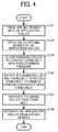
- FIG. 4 is a flowchart illustrating a series of steps in a fixing belt polishing process.
- step S101 the oil application roller 30 is pressed against the applied member being rotated.
- step S102 the oil application roller 30 applies oil to the applied member for a certain amount of time.
- step S103 the polishing roller 41 contacts the fixing belt 22 with a predetermined pressure.
- step S104 the polishing roller 41 rotates with the fixing belt 22 for a certain amount of time to scrape a surface of the fixing belt 22, so that toner wax adhering or attached to the surface of the fixing belt 22 is removed.
- step S105 the polishing roller 41 is separated from the fixing belt 22.
- step S106 the oil application roller 30 applies oil to the applied member for a certain amount of time, and is then separated from the applied member.
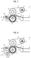
- a fixing device 20 illustrated in FIG. 5 includes a cleaning web unit 31 as another exemplary embodiment of the oil applicator 29 described above.
- the cleaning web unit 31 includes a cleaning web 32 as a cleaner, and a pressure roller 33 as a pressure member for pressing the cleaning web 32 to a pressing roller 27 by an adjuster 340.
- the cleaning web unit 31 is capable of contacting and separating from the pressing roller 27.
- the present exemplary embodiment is described using an example in which the cleaning web unit 31 is capable of contacting and separating from the pressing roller 27, but is not limited thereto.
- the cleaning web unit 31 may be able to contact and separate from a fixing belt 22 or a fixing roller (if a roller fixing method is employed).
- the fixing device 20 In the fixing device 20, toner may adhere to the fixing belt 22, a fixing roller 23, and the pressing roller 27. Such toner adhesion can generate stains on the fixing belt 22, the fixing roller 23, and the pressing roller 27, causing degradation in separability of a recording medium 25 and generation of an irregular image. Consequently, the fixing device 20 preferably has a cleaning function.
- the cleaning web 32 cleans the stain on the pressing roller 27.
- the cleaning web 32 is fed little by little by a cleaning web supply roller 35, and is then wound around a cleaning web winding roller 36. This enables a clean surface of the cleaning web 32 to contact the pressing roller 27, so that the pressing roller 27 is cleaned.
- the cleaning web unit 31 can serve as an oil application surface modifier that has a sliding function and an oil application function in addition to the cleaning function of the original function.
- the sliding function is used so that modifiability of a surface modifier is maintained constant, whereas the oil application function is used for separation assistance.
- Such a cleaning web unit 31 can not only clean offset toner on the fixing belt 22 and the pressing roller 27, but also enhance uniform polishability and separability in the surface modifier by oil application.
- the cleaning web 32 as a cleaner preferably has a long sheet shape.
- the use of the long-sheet-shaped cleaning web 32 impregnated with oil can increase an amount of oil impregnation. Hence, a maintenance cycle can be extended, thereby prolonging the lifespan of the apparatus.
- a term "special color toner” indicates that a special color toner is used, regardless of whether full color toners (Y, M, C, BK) are used at the same time as the special color toner.
- a thickness of thin paper is 105 gsm or less, whereas a thickness of thick paper is 105 gsm or greater.
- a surface of coated paper is coated with white pigment and has good smoothness.
- the oil applicator 29 is controlled to contact and separate from the applied member according to paper thickness of a recording medium and the presence or absence of special color toner use.
- the control is also performed according to a paper type (coated paper/non-coated paper). Therefore, a paper-winding jam in the fixing roller can be prevented.
- a special color toner image is sequentially formed on a conventional full color toner image, and both of the toner images are fixed at the same time. Accordingly, a toner adhesion amount with respect to paper is greater than that in formation of the conventional full color image.
- JP-2002-318482-A and JP-2006-251722-A described above although an adhesion amount of unfixed toner with respect to paper can be reduced, a fixing temperature for only a full color toner image and a fixing temperature for a special color toner image do not necessarily match each other. Consequently, the paper is output from an image forming apparatus at a speed decelerated by 50 % or more. This markedly lowers productivity.
- FIG. 6 A configuration and a control operation of a fixing device according to another exemplary embodiment of the present invention are described with reference to FIG. 6 .
- a fixing device 20 in an axial direction of a fixing roller 23 is illustrated.
- Components and configurations that are similar to the above description will be given the same reference numerals as above and description thereof will be omitted.
- the fixing device 20 illustrated in FIG. 6 includes a cleaning device 50 as another exemplary embodiment of the oil applicator 29 described above.
- the cleaning device 50 includes a cleaning roller 51 as a cleaner, and is presses against at least one of a fixing belt 22 and a pressing roller 27 to clean the fixing belt 22 or the pressing roller 27.
- the cleaning device 50 is in contact with the pressing roller 27.
- the cleaning device 50 may be able to contact the fixing belt 22 or a fixing roller (if a roller fixing method is employed) instead of or in addition to contacting the pressing roller 27.
- the cleaning roller 51 of a porous roller e.g., a silicone sponge roller
- oil e.g., silicone oil
- the cleaning device 50 may include an adjuster with respect to the pressing roller 27 to contact and separate from the pressing roller 27 as similar to the oil applicator 29 of the above exemplary embodiment.
- the adjuster is not particularly limited.
- the adjuster can be a solenoid or cam unit including a drive motor.
- the fixing device 20 includes a lubricant applicator 60 for applying lubricant (oil) to the cleaning roller 51.
- the lubricant applicator 60 supplies oil to the cleaning roller 51.
- the lubricant applicator 60 includes an oil container in which oil is stored, and a shutter controlled to be open and closed at predetermined times.
- the lubricant applicator 60 drops the lubricant from the oil container to the cleaning roller 51 when the shutter is opened at a predetermined time.
- the lubricant is applied to the cleaning roller 51.
- the configuration of the lubricant applicator 60 is not particularly limited.
- the lubricant applicator 60 may contact the cleaning roller 51 to apply lubricant to the cleaning roller 51.
- a type of oil to be applied to the cleaning roller 51 is not particularly limited as long as the oil can be used as a lubricant.
- the oil to be applied to the cleaning roller 51 by the lubricant applicator 60 is preferably the same as that with which the cleaning roller 51 is impregnated.
- a recording medium 25 may be jammed in a fixing nip (a paper jam may occur).
- the fixing device 20 applies oil from the lubricant applicator 60 to the cleaning roller 51 of the cleaning device 50 when recovering from the jam. This can prevent adhesion of the pressing roller 27 to the cleaning roller 51 and maintain cleanability without lowering productivity.
- FIG. 7 A configuration and a control operation of a fixing device according to another exemplary embodiment of the present invention are described with reference to FIG. 7 .
- a fixing device 20 in an axial direction of a fixing roller 23 is illustrated.
- Components and configurations that are similar to the above description will be given the same reference numerals as above and description thereof will be omitted.
- the fixing device 20 illustrated in FIG. 7 includes an oil application roller 61 as an oil supply member, and an adjuster 62 for the oil application roller 61.
- the oil application roller 61 and the adjuster 62 serve as a lubricant applicator 60, and the oil application roller 61 is capable of contacting and separating from a pressing roller 27.
- a cleaning device 50 and the lubricant applicator 60 are in contact with the pressing roller 27.
- the cleaning device 50 and the lubricant applicator 60 may be able to contact a fixing belt 22 or a fixing roller (if a roller fixing method is employed) instead of or in addition to contacting the pressing roller 27.
- the oil application roller 61 is not particularly limited.
- the oil application roller 61 can be an oil-impregnated roller such as a sponge roller, or an oil application roller including an oil supply path through which oil is supplied.
- the adjuster 62 is not particularly limited.
- the adjuster 62 can be a solenoid or cam unit including a drive motor.
- the oil application roller 61 is capable of contacting and separating from the pressing roller 27.
- the oil application roller 61 contacts the pressing roller 27 after a jam occurs. This can prevent adhesion of the cleaning roller 51 to the pressing roller 27.
- the lubricant applicator 60 is preferably disposed with respect to a member that presses the cleaning device 50. That is, the lubricant applicator 60 and the cleaning device 50 are disposed with respect to the same member (herein, the pressing roller 27). Moreover, the lubricant applicator 60 is preferably disposed on an upstream side of the cleaning roller 51 in a rotation direction of the pressing roller 27.
- lubricant to be applied to the pressing roller 27 by the lubricant applicator 60 can be promptly supplied to the cleaning roller 51. This can prevent adhesion of the cleaning roller 51 to the pressing roller 27 and maintain cleanability without lowering productivity.
- a recording medium 25 may be jammed in a fixing nip.
- the fixing device 20 applies oil from the lubricant applicator 60 to the pressing roller 27 when recovering from the jam. This can prevent adhesion of the cleaning roller 51 to the pressing roller 27 and maintain cleanability without lowering productivity.
- FIG. 8 A configuration and a control operation of a fixing device according to another exemplary embodiment of the present invention are described with reference to FIG. 8 .
- a schematic sectional view of FIG. 8 one example of a fixing device 20 in an axial direction of a fixing roller 23 is illustrated.
- Components and configurations that are similar to the above description will be given the same reference numerals as above and description thereof will be omitted.
- the fixing device 20 illustrated in FIG. 8 includes a cleaning web unit 53 as another exemplary embodiment of the cleaning device 50 described above.
- the cleaning web unit 53 includes a cleaning web 54 as a cleaner, and a pressure roller 55 as a pressure member for pressing the cleaning web 54 to a pressing roller 27.
- the cleaning web unit 53 is capable of contacting and separating from the pressing roller 27 using an adjuster 58.
- the present exemplary embodiment is described using an example in which the cleaning web unit 53 is capable of contacting and separating from the pressing roller 27, but is not limited thereto.
- the cleaning web unit 53 may be able to contact and separate from a fixing belt 22 or a fixing roller (if a roller fixing method is employed).
- the cleaning web 54 cleans a stain on the pressing roller 27.
- the cleaning web 54 is fed little by little by a cleaning web supply roller 56, and is then wound around a cleaning web winding roller 57. This enables a clean surface of the cleaning web 54 to contact the pressing roller 27, so that the pressing roller 27 is cleaned.
- the cleaning web unit 53 including the long-sheet-shaped cleaning web 54 impregnated with oil is used as the cleaning device 50.
- the use of such a cleaning web unit 53 can increase an amount of oil impregnation, compared to the use of the cleaning roller 51 (in each of the third and fourth exemplary embodiments). Hence, the lifespan of the cleaner can be prolonged, and a maintenance cycle can be extended.
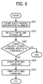
- FIG. 9 is a flowchart illustrating steps in one example of a lubricant application operation according to the present invention.
- the lubricant applicator 60 is preferably controlled whether to apply lubricant according a toner density or a toner adhesion area rate of paper jammed in a fixing nip based on sheet passing information stored beforehand in a storage unit (memory) in an apparatus body of the image forming apparatus 1.
- step S201 the image forming apparatus 1 stores sheet passing information in the memory.
- step S202 the image forming apparatus 1 detects a paper jam in a fixing nip.
- step S203 the image forming apparatus 1 determines whether a toner density and/or a toner adhesion area rate are respective predetermined thresholds or greater.
- step S203 If the toner density and/or the toner adhesion area rate are the respective thresholds or greater (YES in step S203), the process proceeds to step S204 in which the lubricant applicator 60 starts applying lubricant. Subsequently, in step S205, the lubricant applicator 60 finishes applying the lubricant.
- lubricant is preferably applied for a longer time in addition to normal operations.
- the fixing device 20 includes the determination/record unit for determining/recording a toner density and a toner adhesion area rate at the time of paper jam. If the determination/record unit determines that the toner density and/or the toner adhesion area rate exceed respective predetermined values, lubricant is applied. This can suppress a lubricant consumption amount and extend the lifespan of the lubricant applicator 60.
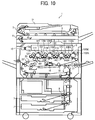
- FIG. 10 is a schematic diagram illustrating a tandem-type color copier as one example of the image forming apparatus 1 according to the exemplary embodiment of the present invention. A configuration and operation of the image forming apparatus are described with reference to FIG. 10 .
- the image forming apparatus 1 includes a writing unit 2, a document conveyance unit 3, a document reading unit 4, a paper feeding unit 7, a registration roller 9, photoconductor drums 11Y, 11M, 11C, and 11BK, charging units 12Y, 12M, 12C, and 12BK, developing units 13Y, 13M, 13C, and 13BK, transfer bias rollers 14Y, 14M, 14C, and 14Bk, and cleaning units 15Y, 15M, 15C, and 15BK.
- the writing unit 2 emits a laser beam based on input image information.
- the document conveyance unit 3 conveys a document D to the document reading unit 4 for reading image information of the document D.
- the paper feeding unit 7 stores a recording medium P (not illustrated) such as a transfer paper.
- the registration roller 9 adjusts conveyance timing of the recording medium P.
- On the photoconductor drums 11Y, 11M, 11C, and 11BK toner images of yellow, magenta, cyan, and black are respectively formed.
- the charging units 12Y, 12M, 12C, and 12BK respectively charge the photoconductor drums 11Y, 11M, 11C, and 11BK.
- the developing units 13Y, 13M, 13C, and 13Bk respectively develop electrostatic latent images formed on the photoconductor drums 11Y, 11M, 11C, and 11BK.
- the transfer bias rollers 14Y, 14M, 14C, and 14Bk as primary transfer bias rollers respectively transfer toner images formed on the photoconductor drums 11Y, 11M, 11C, and 11BK to the recording medium P by overlapping one another.
- the cleaning units 15Y, 15M, 15C, and 15BK respectively collect untransferred toners on the photoconductor drums 11Y, 11M, 11C, and 11 BK.
- the image forming apparatus 1 includes an intermediate transfer belt cleaning unit 16, an intermediate transfer belt 17, a secondary transfer bias roller 18, and the fixing device 20.
- the intermediate transfer belt cleaning unit 16 cleans the intermediate transfer belt 17 to which toner images of plurality of colors are superimposed and transferred.
- the secondary transfer bias roller 18 is used to transfer the color toner image on the intermediate transfer belt 17 to the recording medium P.
- the fixing device 20 fixes the toner image on the recording medium P.
- a document D is conveyed from a document tray to a contact glass 5 of the document reading unit 4.
- the document reading unit 4 optically reads image information of the document D placed on the contact glass 5.
- the document reading unit 4 scans the image of the document D on the contact glass 5 while irradiating the document D with light from an illumination lamp.
- the light reflected by the document D forms an image on a color sensor via a mirror group and a lens.
- the color sensor reads color image information of the document D with respect to each of color separation lights of red, green, and blue (RGB), and then converts the read information into electrical image signals.
- an image processing unit performs processes such as a color conversion process, a color correction process, and a special frequency correction process based on the RGB color separation image signals to obtain image information of yellow, magenta, cyan, and black.
- the image information of each of yellow, magenta, cyan, and black is transmitted to the writing unit 2. Subsequently, the writing unit 2 emits laser beams (exposure light) toward the photoconductor drums 11Y, 11M, 11C, and 11BK based on the image information of the respective colors.
- each of the four photoconductor drums 11Y, 11M, 11C, and 11BK is rotated counterclockwise in FIG. 10 .
- surfaces of the photoconductor drums 11Y, 11M, 11C, and 11BK are uniformly charged in positions opposite the respective charging units 12Y, 12M, 12C, and 12BK (a charging process). Accordingly, charging potentials are formed on the photoconductor drums 11 Y, 11 M, 11C, and 11 BK. Then, the charged surfaces of the photoconductor drums 11Y, 11M, 11C, and 11BK reach respective exposure positions in which the charged surfaces are irradiated with laser beams.
- the writing unit 2 four light sources emit laser beams each corresponding to the image signal for each color.
- the laser beams respectively pass optical paths for yellow, magenta, cyan, and black color components (an exposure process).
- the laser beam corresponding to the yellow component is emitted onto the surface of the photoconductor drum 11Y which is disposed on the far left among the four photoconductor drums 11 in the diagram illustrated in Fig. 10 .
- the laser beam for the yellow component is scanned in a rotation axis direction (a main scanning direction) of the photoconductor drum 11Y by a polygon mirror that is rotating at high speed. Accordingly, an electrostatic latent image corresponding to the yellow component is formed on the photoconductor drum 11Y charged in advance by the charging unit 12Y.
- the laser beam corresponding to the magenta component is emitted onto the surface of the photoconductor drum 11M disposed on the second from the left among the four photoconductor drums 11 in the diagram illustrated in FIG. 10 , so that an electrostatic latent image corresponding to the magenta component is formed.
- the laser beam corresponding to the cyan component is emitted onto the surface of the photoconductor drum 11C disposed on the third from the left among the four photoconductor drums 11 in the diagram illustrated in FIG. 10 , so that an electrostatic latent image corresponding to the cyan component is formed.
- the laser beam corresponding to the black component is emitted onto the surface of the photoconductor drum 11BK disposed on the fourth from the left among the four photoconductor drums 11 in the diagram illustrated in FIG. 10 , so that an electrostatic latent image of the black component is formed.
- the developing units 13Y, 13M, 13C, and 13Bk respectively supply color toners to the photoconductor drums 11Y, 11M, 11C, and 11BK, thereby developing the electrostatic latent images on the photoconductor drums 11Y, 11M, 11C, and 11BK to form toner images (a development process).
- the surfaces of the photoconductor drums 11Y, 11M, 11C, and 11BK reach respective positions opposite the intermediate transfer belt 17.
- the transfer bias rollers 14Y, 14M, 14C, and 14Bk are arranged so as to contact an inner circumferential surface of the intermediate transfer belt 17.
- the transfer bias rollers 14Y, 14M, 14C, and 14Bk the different-color toner images formed on the respective photoconductor drums 11Y, 11M, 11C, and 11BK are sequentially superimposed and transferred to the intermediate transfer belt 17 (a primary transfer process).
- the surfaces of the photoconductor drums 11Y, 11M, 11C, and 11BK reach positions opposite the respective cleaning units 15Y, 15M, 15C, and 15BK.
- the cleaning units 15Y, 15M, 15C, and 15BK respectively collect untransferred toners remaining on the photoconductor drums 11Y, 11M, 11C, and 11BK (a cleaning process).
- the surfaces of the photoconductor drums 11Y, 11M, 11C, and 11BK pass respective discharging units (not illustrated), and a series of the image forming processes in each of the photoconductor drums 11Y, 11M, 11C, and 11BK ends.
- the intermediate transfer belt 17 bearing the toners superimposed and transferred from the respective photoconductor drums 11Y, 11M, 11C, and 11BK, moves clockwise in the diagram illustrated in FIG. 10 , and reaches a position opposite the secondary transfer bias roller 18.
- the color toner image on the intermediate transfer belt 17 is transferred to a recording medium P in the position opposite the secondary transfer bias roller 18 (a secondary transfer process).
- the surface of the intermediate transfer belt 17 reaches a position of the intermediate transfer belt cleaning unit 16 by which untransferred toner on the intermediate transfer belt 17 is collected.
- a series of the transfer processes in the intermediate transfer belt 17 ends.
- the recording medium P conveyed to an area (a secondary transfer nip) between the intermediate transfer belt 17 and the secondary transfer bias roller 18 is conveyed from the paper feeding unit 7 via the registration roller 9.
- the recording medium P stored in the paper feeding unit 7 is fed by a paper feeding roller 8. After passing a conveyance guide, the recording medium P is guided to the registration roller 9. Upon reaching the registration roller 9, the recording medium P is conveyed toward the secondary transfer nip at an appropriate time.
- the recording medium P with a transferred full color image is guided to the fixing device 20 by the conveyance belt.
- the fixing device 20 fixes the color image (toner) onto the recording medium P in a fixing nip between the fixing roller as a fixing rotator and the pressing roller as a pressing rotator.
- the recording medium P is discharged outside the apparatus as an output image by a paper ejection roller, and a series of the image forming processes ends.
- the electrophotographic image forming apparatus repeatedly performs operations such as charging, writing, developing, transferring, cleaning, and discharging with respect to the photoconductor drums as image bearing members to sequentially form toner images and successively transfer the toner images to a recording medium such as a sheet and an overhead projector (OHP) film, thereby recording the image on the recording medium.
- the fixing device allows the recording medium with the transferred toner image to pass an area between the fixing rotator and the pressing rotator to fix the toner image on the recording medium.
- the fixing device conveys the recording medium while suppressing generation of an irregular image (e.g., gloss unevenness) due to adhesion of foreign substances or adherents to the fixing rotator and a separation failure of paper including thin paper and thick paper in the fixing rotator without degrading output image quality.
- an irregular image e.g., gloss unevenness
- the surface modifier modifies a surface of the fixing rotator (the fixing rotator is refreshed). This can not only prevent generation of an irregular image due to re-adhesion of foreign substances/adherents on the fixing rotator to paper or polishing unevenness generated by the surface modifier, but also maintain separability of the paper from the fixing rotator.
- a time period for which the paper passes the fixing device 20 is counted. If a cumulative paper passing time exceeds a predetermined paper passing time, the surface of the fixing rotator is modified (the fixing rotator is refreshed). This can prevent generation of an irregular image due to re-adhesion of foreign substances/adherents on the fixing rotator to the paper or polishing evenness generated by the surface modifier.
- a toner density and a toner adhesion area rate on the paper are determined. If the toner density or a toner adhesion area rate on the paper exceeds a predetermined amount, the surface of the fixing rotator is automatically modified (the fixing rotator is refreshed). This can prevent generation of an irregular image due to re-adhesion of foreign substances/adherents on the fixing rotator to the paper or polishing evenness generated by the surface modifier.
- the surface modifier contacts the fixing rotator to rotate with a linear velocity difference, thereby enhancing removability of foreign substances/adherents from the fixing rotator.
- the oil applicator With the function of determining a toner density and a toner adhesion area rate on the paper, the oil applicator is pressed against the fixing rotator if a toner adhesion amount exceeds a predetermined amount or greater. Thus, even if the paper has a higher toner adhesion amount, the use of oil from the oil applicator can provide separability of the paper with respect to the fixing rotator.
- oil is applied to the fixing rotator, thereby providing separability of the paper with respect to the fixing rotator.
- the cleaner includes a long-sheet-shaped cleaning web, so that the lifespan of the cleaner can be extended and separability of paper with respect to the fixing rotator can be obtained by oil impregnated into the cleaner.
- the image forming apparatus includes the fixing device including the surface modifier capable of contacting and separating from the fixing rotator and the oil applicator capable of contacting and separating from the fixing rotator or a pressing rotator.
- the fixing device including the surface modifier capable of contacting and separating from the fixing rotator and the oil applicator capable of contacting and separating from the fixing rotator or a pressing rotator.
- Such an image forming apparatus is reliable by not only preventing generation of an irregular image due to re-adhesion of foreign substances/adherents on the fixing rotator to paper or polishing unevenness generated by the surface modifier, but also providing separability of the paper with respect to the fixing rotator.
- the cleaner is prevented from adhering to the fixing rotator or the pressing rotator, thereby obtaining fixing-cleanability without lowering productivity.
Landscapes
- Physics & Mathematics (AREA)
- General Physics & Mathematics (AREA)
- Fixing For Electrophotography (AREA)
- Control Or Security For Electrophotography (AREA)
Applications Claiming Priority (2)
| Application Number | Priority Date | Filing Date | Title |
|---|---|---|---|
| JP2015005094 | 2015-01-14 | ||
| JP2015109728A JP6631042B2 (ja) | 2015-01-14 | 2015-05-29 | 定着装置及び画像形成装置 |
Publications (3)
| Publication Number | Publication Date |
|---|---|
| EP3045978A2 true EP3045978A2 (de) | 2016-07-20 |
| EP3045978A3 EP3045978A3 (de) | 2016-10-19 |
| EP3045978B1 EP3045978B1 (de) | 2019-07-03 |
Family
ID=55070877
Family Applications (1)
| Application Number | Title | Priority Date | Filing Date |
|---|---|---|---|
| EP16150330.5A Active EP3045978B1 (de) | 2015-01-14 | 2016-01-06 | Fixiervorrichtung und bilderzeugungsvorrichtung |
Country Status (2)
| Country | Link |
|---|---|
| US (1) | US9568864B2 (de) |
| EP (1) | EP3045978B1 (de) |
Families Citing this family (7)
| Publication number | Priority date | Publication date | Assignee | Title |
|---|---|---|---|---|
| US9785101B2 (en) | 2015-09-28 | 2017-10-10 | Ricoh Company, Ltd. | Fixing device having slider to polish and finish fixing rotator |
| US10191423B2 (en) | 2016-09-28 | 2019-01-29 | Ricoh Company, Ltd. | Image forming apparatus including a fixing device |
| US10488796B2 (en) | 2017-07-05 | 2019-11-26 | Ricoh Company, Ltd. | Fixing device controller, image forming apparatus, fixing device control method, and non-transitory computer-readable recording medium storing fixing device control program |
| JP7057886B2 (ja) | 2017-07-11 | 2022-04-21 | 株式会社リコー | シート搬送装置、定着装置及び画像形成装置 |
| JP6926755B2 (ja) | 2017-07-13 | 2021-08-25 | 株式会社リコー | 定着装置、および画像形成装置 |
| JP7139786B2 (ja) * | 2018-08-27 | 2022-09-21 | 富士フイルムビジネスイノベーション株式会社 | 画像形成装置 |
| JP2021028663A (ja) | 2019-08-09 | 2021-02-25 | 株式会社リコー | 押圧装置、定着装置及び画像形成装置 |
Citations (5)
| Publication number | Priority date | Publication date | Assignee | Title |
|---|---|---|---|---|
| JP2002278347A (ja) | 2001-03-15 | 2002-09-27 | Ricoh Co Ltd | 定着装置及びそれを用いた画像形成装置 |
| JP2002318482A (ja) | 2001-04-20 | 2002-10-31 | Konica Corp | 画像形成装置 |
| JP2006251722A (ja) | 2005-03-14 | 2006-09-21 | Fuji Xerox Co Ltd | 画像形成装置 |
| JP2006259341A (ja) | 2005-03-17 | 2006-09-28 | Ricoh Co Ltd | 定着装置と画像形成装置 |
| JP2011175067A (ja) | 2010-02-24 | 2011-09-08 | Konica Minolta Business Technologies Inc | 定着装置及び画像形成装置 |
Family Cites Families (24)
| Publication number | Priority date | Publication date | Assignee | Title |
|---|---|---|---|---|
| JPS557725A (en) * | 1978-06-30 | 1980-01-19 | Konishiroku Photo Ind Co Ltd | Roller type heat fixing device |
| JP2849003B2 (ja) * | 1992-08-18 | 1999-01-20 | シャープ株式会社 | 電子写真装置 |
| JP2001075402A (ja) * | 1999-09-02 | 2001-03-23 | Canon Inc | 像加熱装置及び画像形成装置 |
| KR100354765B1 (ko) * | 2000-05-15 | 2002-10-05 | 삼성전자 주식회사 | 습식 전자사진방식 인쇄장치 |
| JP2002372885A (ja) * | 2001-06-18 | 2002-12-26 | Ricoh Co Ltd | 液体塗布装置および画像形成装置 |
| US7263322B2 (en) * | 2005-09-30 | 2007-08-28 | Xerox Corporation | Fuser smart cleaning and oiling assembly |
| US20070140754A1 (en) * | 2005-12-21 | 2007-06-21 | Xerox Corporation. | Reusable web cleaning system for a fuser |
| JP5347320B2 (ja) | 2008-05-01 | 2013-11-20 | 株式会社リコー | 定着装置及び画像形成装置 |
| JP5063468B2 (ja) | 2008-05-01 | 2012-10-31 | 株式会社リコー | 定着装置及び画像形成装置 |
| JP5315777B2 (ja) | 2008-05-02 | 2013-10-16 | 株式会社リコー | 定着装置及び画像形成装置 |
| JP2009271245A (ja) | 2008-05-02 | 2009-11-19 | Ricoh Co Ltd | 定着装置及び画像形成装置 |
| JP5117921B2 (ja) | 2008-05-02 | 2013-01-16 | 株式会社リコー | 定着装置及び画像形成装置 |
| JP5167933B2 (ja) * | 2008-05-02 | 2013-03-21 | 株式会社リコー | 画像形成装置 |
| JP5347322B2 (ja) | 2008-05-02 | 2013-11-20 | 株式会社リコー | 画像形成装置 |
| JP5365784B2 (ja) | 2009-03-17 | 2013-12-11 | 株式会社リコー | 定着装置及び画像形成装置 |
| CN102033470A (zh) * | 2009-09-29 | 2011-04-27 | 株式会社东芝 | 定影装置、图像形成装置及残留色调剂的剥离方法 |
| JP5494046B2 (ja) | 2010-03-12 | 2014-05-14 | 株式会社リコー | 画像形成装置 |
| JP2012163907A (ja) | 2011-02-09 | 2012-08-30 | Ricoh Co Ltd | 画像形成装置 |
| JP2014021205A (ja) | 2012-07-13 | 2014-02-03 | Ricoh Co Ltd | 定着装置および画像形成装置 |
| JP6051773B2 (ja) | 2012-10-29 | 2016-12-27 | 株式会社リコー | 定着装置及び画像形成装置 |
| JP2015087738A (ja) | 2013-02-21 | 2015-05-07 | 株式会社リコー | 定着装置および画像形成装置 |
| JP2014164074A (ja) | 2013-02-25 | 2014-09-08 | Ricoh Co Ltd | 定着装置 |
| JP2014215376A (ja) | 2013-04-24 | 2014-11-17 | 株式会社リコー | 定着装置、定着装置の制御方法および画像形成装置 |
| JP6187116B2 (ja) | 2013-10-04 | 2017-08-30 | 株式会社リコー | 定着装置及び画像形成装置 |
-
2016
- 2016-01-06 EP EP16150330.5A patent/EP3045978B1/de active Active
- 2016-01-12 US US14/993,565 patent/US9568864B2/en not_active Expired - Fee Related
Patent Citations (5)
| Publication number | Priority date | Publication date | Assignee | Title |
|---|---|---|---|---|
| JP2002278347A (ja) | 2001-03-15 | 2002-09-27 | Ricoh Co Ltd | 定着装置及びそれを用いた画像形成装置 |
| JP2002318482A (ja) | 2001-04-20 | 2002-10-31 | Konica Corp | 画像形成装置 |
| JP2006251722A (ja) | 2005-03-14 | 2006-09-21 | Fuji Xerox Co Ltd | 画像形成装置 |
| JP2006259341A (ja) | 2005-03-17 | 2006-09-28 | Ricoh Co Ltd | 定着装置と画像形成装置 |
| JP2011175067A (ja) | 2010-02-24 | 2011-09-08 | Konica Minolta Business Technologies Inc | 定着装置及び画像形成装置 |
Also Published As
| Publication number | Publication date |
|---|---|
| EP3045978A3 (de) | 2016-10-19 |
| US20160202646A1 (en) | 2016-07-14 |
| EP3045978B1 (de) | 2019-07-03 |
| US9568864B2 (en) | 2017-02-14 |
Similar Documents
| Publication | Publication Date | Title |
|---|---|---|
| EP3045978B1 (de) | Fixiervorrichtung und bilderzeugungsvorrichtung | |
| US8095042B2 (en) | Image forming apparatus and method of controlling same | |
| JP5900389B2 (ja) | 定着装置及び画像形成装置 | |
| US8948641B2 (en) | Fixing device and control method used therein | |
| JP6561600B2 (ja) | 定着装置及び画像形成装置 | |
| JP2002357968A (ja) | 定着装置及びこれを用いた画像形成装置 | |
| JP2007034068A (ja) | 定着装置および画像形成装置 | |
| JP7229461B2 (ja) | 定着装置、及び、画像形成装置 | |
| JP6135209B2 (ja) | 定着装置、画像形成装置、および定着装置の保守方法 | |
| JP2009222810A (ja) | 定着装置及びこれを備えた画像形成装置 | |
| JP2014215376A (ja) | 定着装置、定着装置の制御方法および画像形成装置 | |
| JP7563114B2 (ja) | 画像形成装置 | |
| JP6631042B2 (ja) | 定着装置及び画像形成装置 | |
| JP2010181512A (ja) | 定着装置、及び、画像形成装置 | |
| US20060039716A1 (en) | Image forming apparatus | |
| JP2012042535A (ja) | 定着装置、及び、画像形成装置 | |
| JP2012194444A (ja) | 定着装置及びその定着装置を備えた画像形成装置 | |
| JP6187116B2 (ja) | 定着装置及び画像形成装置 | |
| JP6855766B2 (ja) | 定着装置、および画像形成装置 | |
| JP2017009661A (ja) | 画像形成装置及び定着用回転部材の表面状態改善方法 | |
| JP6682296B2 (ja) | 画像形成装置 | |
| JP4934350B2 (ja) | 定着装置、画像形成装置 | |
| JP2012098610A (ja) | 定着装置および画像形成装置 | |
| JP7157371B2 (ja) | 帯電装置、プロセスカートリッジ、及び、画像形成装置 | |
| JP6198000B2 (ja) | 定着装置、及び、画像形成装置 |
Legal Events
| Date | Code | Title | Description |
|---|---|---|---|
| PUAI | Public reference made under article 153(3) epc to a published international application that has entered the european phase |
Free format text: ORIGINAL CODE: 0009012 |
|
| 17P | Request for examination filed |
Effective date: 20160106 |
|
| AK | Designated contracting states |
Kind code of ref document: A2 Designated state(s): AL AT BE BG CH CY CZ DE DK EE ES FI FR GB GR HR HU IE IS IT LI LT LU LV MC MK MT NL NO PL PT RO RS SE SI SK SM TR |
|
| AX | Request for extension of the european patent |
Extension state: BA ME |
|
| PUAL | Search report despatched |
Free format text: ORIGINAL CODE: 0009013 |
|
| AK | Designated contracting states |
Kind code of ref document: A3 Designated state(s): AL AT BE BG CH CY CZ DE DK EE ES FI FR GB GR HR HU IE IS IT LI LT LU LV MC MK MT NL NO PL PT RO RS SE SI SK SM TR |
|
| AX | Request for extension of the european patent |
Extension state: BA ME |
|
| RIC1 | Information provided on ipc code assigned before grant |
Ipc: G03G 15/20 20060101AFI20160914BHEP |
|
| GRAP | Despatch of communication of intention to grant a patent |
Free format text: ORIGINAL CODE: EPIDOSNIGR1 |
|
| STAA | Information on the status of an ep patent application or granted ep patent |
Free format text: STATUS: GRANT OF PATENT IS INTENDED |
|
| INTG | Intention to grant announced |
Effective date: 20190211 |
|
| GRAS | Grant fee paid |
Free format text: ORIGINAL CODE: EPIDOSNIGR3 |
|
| GRAA | (expected) grant |
Free format text: ORIGINAL CODE: 0009210 |
|
| STAA | Information on the status of an ep patent application or granted ep patent |
Free format text: STATUS: THE PATENT HAS BEEN GRANTED |
|
| AK | Designated contracting states |
Kind code of ref document: B1 Designated state(s): AL AT BE BG CH CY CZ DE DK EE ES FI FR GB GR HR HU IE IS IT LI LT LU LV MC MK MT NL NO PL PT RO RS SE SI SK SM TR |
|
| REG | Reference to a national code |
Ref country code: GB Ref legal event code: FG4D |
|
| REG | Reference to a national code |
Ref country code: AT Ref legal event code: REF Ref document number: 1151719 Country of ref document: AT Kind code of ref document: T Effective date: 20190715 Ref country code: CH Ref legal event code: EP |
|
| REG | Reference to a national code |
Ref country code: IE Ref legal event code: FG4D |
|
| REG | Reference to a national code |
Ref country code: DE Ref legal event code: R096 Ref document number: 602016016102 Country of ref document: DE |
|
| REG | Reference to a national code |
Ref country code: NL Ref legal event code: MP Effective date: 20190703 |
|
| REG | Reference to a national code |
Ref country code: LT Ref legal event code: MG4D |
|
| REG | Reference to a national code |
Ref country code: AT Ref legal event code: MK05 Ref document number: 1151719 Country of ref document: AT Kind code of ref document: T Effective date: 20190703 |
|
| PG25 | Lapsed in a contracting state [announced via postgrant information from national office to epo] |
Ref country code: CZ Free format text: LAPSE BECAUSE OF FAILURE TO SUBMIT A TRANSLATION OF THE DESCRIPTION OR TO PAY THE FEE WITHIN THE PRESCRIBED TIME-LIMIT Effective date: 20190703 Ref country code: NL Free format text: LAPSE BECAUSE OF FAILURE TO SUBMIT A TRANSLATION OF THE DESCRIPTION OR TO PAY THE FEE WITHIN THE PRESCRIBED TIME-LIMIT Effective date: 20190703 Ref country code: BG Free format text: LAPSE BECAUSE OF FAILURE TO SUBMIT A TRANSLATION OF THE DESCRIPTION OR TO PAY THE FEE WITHIN THE PRESCRIBED TIME-LIMIT Effective date: 20191003 Ref country code: AT Free format text: LAPSE BECAUSE OF FAILURE TO SUBMIT A TRANSLATION OF THE DESCRIPTION OR TO PAY THE FEE WITHIN THE PRESCRIBED TIME-LIMIT Effective date: 20190703 Ref country code: PT Free format text: LAPSE BECAUSE OF FAILURE TO SUBMIT A TRANSLATION OF THE DESCRIPTION OR TO PAY THE FEE WITHIN THE PRESCRIBED TIME-LIMIT Effective date: 20191104 Ref country code: HR Free format text: LAPSE BECAUSE OF FAILURE TO SUBMIT A TRANSLATION OF THE DESCRIPTION OR TO PAY THE FEE WITHIN THE PRESCRIBED TIME-LIMIT Effective date: 20190703 Ref country code: LT Free format text: LAPSE BECAUSE OF FAILURE TO SUBMIT A TRANSLATION OF THE DESCRIPTION OR TO PAY THE FEE WITHIN THE PRESCRIBED TIME-LIMIT Effective date: 20190703 Ref country code: FI Free format text: LAPSE BECAUSE OF FAILURE TO SUBMIT A TRANSLATION OF THE DESCRIPTION OR TO PAY THE FEE WITHIN THE PRESCRIBED TIME-LIMIT Effective date: 20190703 Ref country code: SE Free format text: LAPSE BECAUSE OF FAILURE TO SUBMIT A TRANSLATION OF THE DESCRIPTION OR TO PAY THE FEE WITHIN THE PRESCRIBED TIME-LIMIT Effective date: 20190703 Ref country code: NO Free format text: LAPSE BECAUSE OF FAILURE TO SUBMIT A TRANSLATION OF THE DESCRIPTION OR TO PAY THE FEE WITHIN THE PRESCRIBED TIME-LIMIT Effective date: 20191003 |
|
| PG25 | Lapsed in a contracting state [announced via postgrant information from national office to epo] |
Ref country code: ES Free format text: LAPSE BECAUSE OF FAILURE TO SUBMIT A TRANSLATION OF THE DESCRIPTION OR TO PAY THE FEE WITHIN THE PRESCRIBED TIME-LIMIT Effective date: 20190703 Ref country code: IS Free format text: LAPSE BECAUSE OF FAILURE TO SUBMIT A TRANSLATION OF THE DESCRIPTION OR TO PAY THE FEE WITHIN THE PRESCRIBED TIME-LIMIT Effective date: 20191103 Ref country code: RS Free format text: LAPSE BECAUSE OF FAILURE TO SUBMIT A TRANSLATION OF THE DESCRIPTION OR TO PAY THE FEE WITHIN THE PRESCRIBED TIME-LIMIT Effective date: 20190703 Ref country code: LV Free format text: LAPSE BECAUSE OF FAILURE TO SUBMIT A TRANSLATION OF THE DESCRIPTION OR TO PAY THE FEE WITHIN THE PRESCRIBED TIME-LIMIT Effective date: 20190703 Ref country code: AL Free format text: LAPSE BECAUSE OF FAILURE TO SUBMIT A TRANSLATION OF THE DESCRIPTION OR TO PAY THE FEE WITHIN THE PRESCRIBED TIME-LIMIT Effective date: 20190703 Ref country code: GR Free format text: LAPSE BECAUSE OF FAILURE TO SUBMIT A TRANSLATION OF THE DESCRIPTION OR TO PAY THE FEE WITHIN THE PRESCRIBED TIME-LIMIT Effective date: 20191004 |
|
| PG25 | Lapsed in a contracting state [announced via postgrant information from national office to epo] |
Ref country code: TR Free format text: LAPSE BECAUSE OF FAILURE TO SUBMIT A TRANSLATION OF THE DESCRIPTION OR TO PAY THE FEE WITHIN THE PRESCRIBED TIME-LIMIT Effective date: 20190703 |
|
| PG25 | Lapsed in a contracting state [announced via postgrant information from national office to epo] |
Ref country code: EE Free format text: LAPSE BECAUSE OF FAILURE TO SUBMIT A TRANSLATION OF THE DESCRIPTION OR TO PAY THE FEE WITHIN THE PRESCRIBED TIME-LIMIT Effective date: 20190703 Ref country code: DK Free format text: LAPSE BECAUSE OF FAILURE TO SUBMIT A TRANSLATION OF THE DESCRIPTION OR TO PAY THE FEE WITHIN THE PRESCRIBED TIME-LIMIT Effective date: 20190703 Ref country code: PL Free format text: LAPSE BECAUSE OF FAILURE TO SUBMIT A TRANSLATION OF THE DESCRIPTION OR TO PAY THE FEE WITHIN THE PRESCRIBED TIME-LIMIT Effective date: 20190703 Ref country code: RO Free format text: LAPSE BECAUSE OF FAILURE TO SUBMIT A TRANSLATION OF THE DESCRIPTION OR TO PAY THE FEE WITHIN THE PRESCRIBED TIME-LIMIT Effective date: 20190703 Ref country code: IT Free format text: LAPSE BECAUSE OF FAILURE TO SUBMIT A TRANSLATION OF THE DESCRIPTION OR TO PAY THE FEE WITHIN THE PRESCRIBED TIME-LIMIT Effective date: 20190703 |
|
| PG25 | Lapsed in a contracting state [announced via postgrant information from national office to epo] |
Ref country code: SK Free format text: LAPSE BECAUSE OF FAILURE TO SUBMIT A TRANSLATION OF THE DESCRIPTION OR TO PAY THE FEE WITHIN THE PRESCRIBED TIME-LIMIT Effective date: 20190703 Ref country code: SM Free format text: LAPSE BECAUSE OF FAILURE TO SUBMIT A TRANSLATION OF THE DESCRIPTION OR TO PAY THE FEE WITHIN THE PRESCRIBED TIME-LIMIT Effective date: 20190703 Ref country code: IS Free format text: LAPSE BECAUSE OF FAILURE TO SUBMIT A TRANSLATION OF THE DESCRIPTION OR TO PAY THE FEE WITHIN THE PRESCRIBED TIME-LIMIT Effective date: 20200224 |
|
| REG | Reference to a national code |
Ref country code: DE Ref legal event code: R097 Ref document number: 602016016102 Country of ref document: DE |
|
| PLBE | No opposition filed within time limit |
Free format text: ORIGINAL CODE: 0009261 |
|
| STAA | Information on the status of an ep patent application or granted ep patent |
Free format text: STATUS: NO OPPOSITION FILED WITHIN TIME LIMIT |
|
| PG2D | Information on lapse in contracting state deleted |
Ref country code: IS |
|
| 26N | No opposition filed |
Effective date: 20200603 |
|
| PG25 | Lapsed in a contracting state [announced via postgrant information from national office to epo] |
Ref country code: SI Free format text: LAPSE BECAUSE OF FAILURE TO SUBMIT A TRANSLATION OF THE DESCRIPTION OR TO PAY THE FEE WITHIN THE PRESCRIBED TIME-LIMIT Effective date: 20190703 Ref country code: MC Free format text: LAPSE BECAUSE OF FAILURE TO SUBMIT A TRANSLATION OF THE DESCRIPTION OR TO PAY THE FEE WITHIN THE PRESCRIBED TIME-LIMIT Effective date: 20190703 |
|
| REG | Reference to a national code |
Ref country code: CH Ref legal event code: PL |
|
| REG | Reference to a national code |
Ref country code: BE Ref legal event code: MM Effective date: 20200131 |
|
| PG25 | Lapsed in a contracting state [announced via postgrant information from national office to epo] |
Ref country code: LU Free format text: LAPSE BECAUSE OF NON-PAYMENT OF DUE FEES Effective date: 20200106 |
|
| PG25 | Lapsed in a contracting state [announced via postgrant information from national office to epo] |
Ref country code: BE Free format text: LAPSE BECAUSE OF NON-PAYMENT OF DUE FEES Effective date: 20200131 Ref country code: LI Free format text: LAPSE BECAUSE OF NON-PAYMENT OF DUE FEES Effective date: 20200131 Ref country code: CH Free format text: LAPSE BECAUSE OF NON-PAYMENT OF DUE FEES Effective date: 20200131 |
|
| PG25 | Lapsed in a contracting state [announced via postgrant information from national office to epo] |
Ref country code: IE Free format text: LAPSE BECAUSE OF NON-PAYMENT OF DUE FEES Effective date: 20200106 |
|
| PGFP | Annual fee paid to national office [announced via postgrant information from national office to epo] |
Ref country code: FR Payment date: 20210122 Year of fee payment: 6 |
|
| PGFP | Annual fee paid to national office [announced via postgrant information from national office to epo] |
Ref country code: GB Payment date: 20210121 Year of fee payment: 6 Ref country code: DE Payment date: 20210120 Year of fee payment: 6 |
|
| PG25 | Lapsed in a contracting state [announced via postgrant information from national office to epo] |
Ref country code: MT Free format text: LAPSE BECAUSE OF FAILURE TO SUBMIT A TRANSLATION OF THE DESCRIPTION OR TO PAY THE FEE WITHIN THE PRESCRIBED TIME-LIMIT Effective date: 20190703 Ref country code: CY Free format text: LAPSE BECAUSE OF FAILURE TO SUBMIT A TRANSLATION OF THE DESCRIPTION OR TO PAY THE FEE WITHIN THE PRESCRIBED TIME-LIMIT Effective date: 20190703 |
|
| PG25 | Lapsed in a contracting state [announced via postgrant information from national office to epo] |
Ref country code: MK Free format text: LAPSE BECAUSE OF FAILURE TO SUBMIT A TRANSLATION OF THE DESCRIPTION OR TO PAY THE FEE WITHIN THE PRESCRIBED TIME-LIMIT Effective date: 20190703 |
|
| REG | Reference to a national code |
Ref country code: DE Ref legal event code: R119 Ref document number: 602016016102 Country of ref document: DE |
|
| GBPC | Gb: european patent ceased through non-payment of renewal fee |
Effective date: 20220106 |
|
| PG25 | Lapsed in a contracting state [announced via postgrant information from national office to epo] |
Ref country code: GB Free format text: LAPSE BECAUSE OF NON-PAYMENT OF DUE FEES Effective date: 20220106 Ref country code: DE Free format text: LAPSE BECAUSE OF NON-PAYMENT OF DUE FEES Effective date: 20220802 |
|
| PG25 | Lapsed in a contracting state [announced via postgrant information from national office to epo] |
Ref country code: FR Free format text: LAPSE BECAUSE OF NON-PAYMENT OF DUE FEES Effective date: 20220131 |