EP3025908A1 - Dispositif comprenant un capteur de mouvement exterieur et balise lumineuse pour un vehicule automobile - Google Patents
Dispositif comprenant un capteur de mouvement exterieur et balise lumineuse pour un vehicule automobile Download PDFInfo
- Publication number
- EP3025908A1 EP3025908A1 EP15192940.3A EP15192940A EP3025908A1 EP 3025908 A1 EP3025908 A1 EP 3025908A1 EP 15192940 A EP15192940 A EP 15192940A EP 3025908 A1 EP3025908 A1 EP 3025908A1
- Authority
- EP
- European Patent Office
- Prior art keywords
- motor vehicle
- light
- sensor
- designed
- luminous
- Prior art date
- Legal status (The legal status is an assumption and is not a legal conclusion. Google has not performed a legal analysis and makes no representation as to the accuracy of the status listed.)
- Granted
Links
- 230000033001 locomotion Effects 0.000 title description 12
- 238000001514 detection method Methods 0.000 claims abstract description 34
- 238000009434 installation Methods 0.000 claims abstract description 14
- 230000001419 dependent effect Effects 0.000 claims abstract description 5
- 230000003287 optical effect Effects 0.000 claims description 29
- 230000007935 neutral effect Effects 0.000 claims description 3
- 230000005855 radiation Effects 0.000 claims description 3
- 239000003550 marker Substances 0.000 claims description 2
- 230000008901 benefit Effects 0.000 description 18
- 238000011161 development Methods 0.000 description 7
- 230000018109 developmental process Effects 0.000 description 7
- 230000008878 coupling Effects 0.000 description 4
- 238000010168 coupling process Methods 0.000 description 4
- 238000005859 coupling reaction Methods 0.000 description 4
- 238000001816 cooling Methods 0.000 description 3
- 238000005286 illumination Methods 0.000 description 3
- 230000004913 activation Effects 0.000 description 2
- 238000011109 contamination Methods 0.000 description 2
- 239000000463 material Substances 0.000 description 2
- 230000004044 response Effects 0.000 description 2
- 239000000853 adhesive Substances 0.000 description 1
- 230000001070 adhesive effect Effects 0.000 description 1
- -1 dirt Substances 0.000 description 1
- 230000009977 dual effect Effects 0.000 description 1
- 239000000428 dust Substances 0.000 description 1
- 230000001771 impaired effect Effects 0.000 description 1
- 238000001746 injection moulding Methods 0.000 description 1
- 230000010354 integration Effects 0.000 description 1
- 238000002604 ultrasonography Methods 0.000 description 1
Images

Classifications
-
- B—PERFORMING OPERATIONS; TRANSPORTING
- B60—VEHICLES IN GENERAL
- B60R—VEHICLES, VEHICLE FITTINGS, OR VEHICLE PARTS, NOT OTHERWISE PROVIDED FOR
- B60R25/00—Fittings or systems for preventing or indicating unauthorised use or theft of vehicles
- B60R25/20—Means to switch the anti-theft system on or off
- B60R25/2054—Means to switch the anti-theft system on or off by foot gestures
-
- B—PERFORMING OPERATIONS; TRANSPORTING
- B60—VEHICLES IN GENERAL
- B60Q—ARRANGEMENT OF SIGNALLING OR LIGHTING DEVICES, THE MOUNTING OR SUPPORTING THEREOF OR CIRCUITS THEREFOR, FOR VEHICLES IN GENERAL
- B60Q1/00—Arrangement of optical signalling or lighting devices, the mounting or supporting thereof or circuits therefor
- B60Q1/26—Arrangement of optical signalling or lighting devices, the mounting or supporting thereof or circuits therefor the devices being primarily intended to indicate the vehicle, or parts thereof, or to give signals, to other traffic
- B60Q1/2607—Arrangement of optical signalling or lighting devices, the mounting or supporting thereof or circuits therefor the devices being primarily intended to indicate the vehicle, or parts thereof, or to give signals, to other traffic comprising at least two indicating lamps
-
- B—PERFORMING OPERATIONS; TRANSPORTING
- B60—VEHICLES IN GENERAL
- B60Q—ARRANGEMENT OF SIGNALLING OR LIGHTING DEVICES, THE MOUNTING OR SUPPORTING THEREOF OR CIRCUITS THEREFOR, FOR VEHICLES IN GENERAL
- B60Q1/00—Arrangement of optical signalling or lighting devices, the mounting or supporting thereof or circuits therefor
- B60Q1/26—Arrangement of optical signalling or lighting devices, the mounting or supporting thereof or circuits therefor the devices being primarily intended to indicate the vehicle, or parts thereof, or to give signals, to other traffic
- B60Q1/2661—Arrangement of optical signalling or lighting devices, the mounting or supporting thereof or circuits therefor the devices being primarily intended to indicate the vehicle, or parts thereof, or to give signals, to other traffic mounted on parts having other functions
- B60Q1/2669—Arrangement of optical signalling or lighting devices, the mounting or supporting thereof or circuits therefor the devices being primarily intended to indicate the vehicle, or parts thereof, or to give signals, to other traffic mounted on parts having other functions on door or boot handles
-
- B—PERFORMING OPERATIONS; TRANSPORTING
- B60—VEHICLES IN GENERAL
- B60Q—ARRANGEMENT OF SIGNALLING OR LIGHTING DEVICES, THE MOUNTING OR SUPPORTING THEREOF OR CIRCUITS THEREFOR, FOR VEHICLES IN GENERAL
- B60Q1/00—Arrangement of optical signalling or lighting devices, the mounting or supporting thereof or circuits therefor
- B60Q1/26—Arrangement of optical signalling or lighting devices, the mounting or supporting thereof or circuits therefor the devices being primarily intended to indicate the vehicle, or parts thereof, or to give signals, to other traffic
- B60Q1/32—Arrangement of optical signalling or lighting devices, the mounting or supporting thereof or circuits therefor the devices being primarily intended to indicate the vehicle, or parts thereof, or to give signals, to other traffic for indicating vehicle sides, e.g. clearance lights
- B60Q1/323—Arrangement of optical signalling or lighting devices, the mounting or supporting thereof or circuits therefor the devices being primarily intended to indicate the vehicle, or parts thereof, or to give signals, to other traffic for indicating vehicle sides, e.g. clearance lights on or for doors
-
- E—FIXED CONSTRUCTIONS
- E05—LOCKS; KEYS; WINDOW OR DOOR FITTINGS; SAFES
- E05F—DEVICES FOR MOVING WINGS INTO OPEN OR CLOSED POSITION; CHECKS FOR WINGS; WING FITTINGS NOT OTHERWISE PROVIDED FOR, CONCERNED WITH THE FUNCTIONING OF THE WING
- E05F15/00—Power-operated mechanisms for wings
- E05F15/70—Power-operated mechanisms for wings with automatic actuation
- E05F15/73—Power-operated mechanisms for wings with automatic actuation responsive to movement or presence of persons or objects
-
- B—PERFORMING OPERATIONS; TRANSPORTING
- B60—VEHICLES IN GENERAL
- B60Q—ARRANGEMENT OF SIGNALLING OR LIGHTING DEVICES, THE MOUNTING OR SUPPORTING THEREOF OR CIRCUITS THEREFOR, FOR VEHICLES IN GENERAL
- B60Q2400/00—Special features or arrangements of exterior signal lamps for vehicles
- B60Q2400/50—Projected symbol or information, e.g. onto the road or car body
-
- E—FIXED CONSTRUCTIONS
- E05—LOCKS; KEYS; WINDOW OR DOOR FITTINGS; SAFES
- E05Y—INDEXING SCHEME ASSOCIATED WITH SUBCLASSES E05D AND E05F, RELATING TO CONSTRUCTION ELEMENTS, ELECTRIC CONTROL, POWER SUPPLY, POWER SIGNAL OR TRANSMISSION, USER INTERFACES, MOUNTING OR COUPLING, DETAILS, ACCESSORIES, AUXILIARY OPERATIONS NOT OTHERWISE PROVIDED FOR, APPLICATION THEREOF
- E05Y2400/00—Electronic control; Electrical power; Power supply; Power or signal transmission; User interfaces
- E05Y2400/80—User interfaces
- E05Y2400/85—User input means
- E05Y2400/852—Sensors
-
- E—FIXED CONSTRUCTIONS
- E05—LOCKS; KEYS; WINDOW OR DOOR FITTINGS; SAFES
- E05Y—INDEXING SCHEME ASSOCIATED WITH SUBCLASSES E05D AND E05F, RELATING TO CONSTRUCTION ELEMENTS, ELECTRIC CONTROL, POWER SUPPLY, POWER SIGNAL OR TRANSMISSION, USER INTERFACES, MOUNTING OR COUPLING, DETAILS, ACCESSORIES, AUXILIARY OPERATIONS NOT OTHERWISE PROVIDED FOR, APPLICATION THEREOF
- E05Y2400/00—Electronic control; Electrical power; Power supply; Power or signal transmission; User interfaces
- E05Y2400/80—User interfaces
- E05Y2400/85—User input means
- E05Y2400/856—Actuation thereof
- E05Y2400/858—Actuation thereof by body parts, e.g. by feet
-
- E—FIXED CONSTRUCTIONS
- E05—LOCKS; KEYS; WINDOW OR DOOR FITTINGS; SAFES
- E05Y—INDEXING SCHEME ASSOCIATED WITH SUBCLASSES E05D AND E05F, RELATING TO CONSTRUCTION ELEMENTS, ELECTRIC CONTROL, POWER SUPPLY, POWER SIGNAL OR TRANSMISSION, USER INTERFACES, MOUNTING OR COUPLING, DETAILS, ACCESSORIES, AUXILIARY OPERATIONS NOT OTHERWISE PROVIDED FOR, APPLICATION THEREOF
- E05Y2900/00—Application of doors, windows, wings or fittings thereof
- E05Y2900/50—Application of doors, windows, wings or fittings thereof for vehicles
- E05Y2900/53—Type of wing
- E05Y2900/546—Tailboards, tailgates or sideboards opening upwards
Definitions
- the invention relates to a device for a motor vehicle with a sensor device for detecting an object, in particular a body part, in a detection area outside the motor vehicle and with a lighting device for marking the detection area.
- the invention also includes a vehicle lamp and a motor vehicle.
- a device of the type mentioned is for example from the EP 1 902 912 A1 known. Thereafter, the device comprises a sensor device which monitors for the presence of a body part of a user or an object in an outer area of a motor vehicle and when recognizing a body movement of a leg or foot next to the motor vehicle opens the tailgate or boot lid of the motor vehicle. It may be provided a marking means, for example, generates a point of light on the ground.
- a motion detector for a motor vehicle which radiates modulated light on a floor surface in an environment of the motor vehicle. Two different areas on the floor are illuminated. If a user disturbs one of the illuminated areas with his foot, this is detected as movement and a tailgate of the motor vehicle is opened.
- optical tailgate openers has been recognized as a disadvantage that when pollution of the lighting device, which is to project the luminous marking on the floor surface, this luminous marking is no longer recognizable by the user. Then the user does not know where to pivot with his foot in order to trigger the opening of the tailgate.
- the invention is based on the object, in a motor vehicle with vehicle-external detection area for detecting a presence of an object, in particular a body part, to mark the detection area for the user reliably.
- a device for a motor vehicle which has a sensor device and a lighting device.
- the sensor device has a sensor housing or housing for short, which can be fastened or arranged in a predetermined first installation position on a first component of the motor vehicle.
- the housing may be e.g. a flange for screwing or an adhesive surface for adhering to the first component.
- at least one sensor element is arranged, which in the intended first installation position of the housing has a to a bottom surface of an environment of the motor vehicle, in particular to a road, extending detection area and is designed to one of a presence of an object, in particular a Body part of a user to generate in the detection area dependent sensor signal.
- the detection range of the at least one sensor element downwards, when the housing is arranged as intended in the first installation position in the motor vehicle. It can be provided here that the presence of the object and / or a movement of the object is signaled.
- the lighting device is designed to generate a light spot or a luminous marking by emitting light in a region of the floor area covered by the detection area.
- the luminous marking is smaller than the area on the bottom surface, which is detected or covered by the detection area of the at least one sensor element. In other words, at least one light beam of the light then penetrates the detection area.
- the lighting device can illuminate into the detection area.
- the lighting device is arranged outside the housing of the sensor device.
- the housing and the lighting device are provided prior to installation in the motor vehicle as two individual components that can be positioned or arranged independently of one another in the motor vehicle.
- the lighting device is designed to be arrangeable in one of the first component, on which the housing is arranged, different second component of the motor vehicle.
- the lighting device may be arranged in a region of the second component, ie on the second component.
- the invention provides a motor vehicle in which an embodiment of the device according to the invention is provided.
- the lighting device can be arranged independently of the sensor device in or on a second component of the motor vehicle. This makes it possible in an advantageous manner to attach the sensor device to a first component, from where the sensing of the presence of the object can be carried out particularly reliably, for example, close to the bottom surface.
- the sensor device in the motor vehicle according to the invention at a distance of at most 80 cm, in particular at most 60 cm, arranged away from the bottom surface.
- the lighting device can be arranged on or in the second component, which can be selected such that it is a component which is less likely to be contaminated or concealed than the first component. This ensures that the light emission from the lighting device to the bottom surface is not affected by adhering to the second component dirt.
- the lighting device is designed to be arrangeable in a second installation position in the motor vehicle, wherein the second mounting position along a vehicle vertical axis of the motor vehicle arranged higher than the first intended installation position of the housing.
- the lighting device is preferably arranged above the sensor device in the motor vehicle according to the invention, wherein above also includes obliquely above.
- the first component is arranged closer to the bottom surface than the second component.
- An installation height of the lighting device is preferably at least 60 cm, in particular at least 80 cm. This results in the advantage that the lighting device is covered with a lower probability of, for example, when driving thrown up material, such as dirt, dust, snow and / or mud.
- the housing is configured fastened to a bumper or a footboard or a tailgate.
- the sensor device By arranging the sensor device on the bumper or running board, there is the advantage that the sensor device is located at a distance of at most 80 cm, in particular at most 60 cm from the bottom surface. As a result, the detection of the object is particularly reliable.
- the arrangement on the tailgate has the advantage that, for example, a reversing camera can be used as a sensor element.
- the provision of the sensor device in the running board has the advantage that motion detection in the area of a driver's door or another vehicle door is made possible.
- the at least one sensor element of the sensor device in each case has an optical receiver, in particular a photosensitive sensor, or a camera or an ultrasonic sensor.
- An optical receiver can be provided with particularly low technical effort.
- a camera can advantageously be fed to a dual function. For example, a reversing camera can be used, which can be used by the driver during rearward travel of the motor vehicle to view the rear area. The camera can be arranged in particular in the manner described in a tailgate of the motor vehicle.
- An ultrasonic sensor has the advantage that a detection of an object in the detection area is possible even when the soiled first component through a dirt layer.
- the lighting device is coupled to a brightness sensor which is designed to generate a brightness signal correlating with an ambient brightness.
- a brightness sensor can be provided in a motor vehicle, for example, for switching between daytime running lights and low beam.
- the brightness sensor can also be realized for example by means of a camera of the motor vehicle.
- the lighting device is designed to set a radiation intensity of the light emitted for generating the luminous marking as a function of the brightness signal of the brightness sensor. This results in the advantage that, depending on the ambient light, a luminous marking recognizable by the user through a predetermined minimum contrast can be generated on the floor surface.
- the sensor device is designed to be coupled to a locking system of the motor vehicle and a control device of the sensor device is adapted to unlock depending on the sensor signal of the at least one sensor element by emitting a control signal to the locking system a flap of the motor vehicle, in particular a tailgate and / or open.
- a corresponding actuator or motor can be provided to open the tailgate.
- the already described optical tailgate opener can be provided in an advantageous manner.
- an electrical interface in particular a plug or a socket or a bus coupling unit.
- the lighting device is designed to generate the illuminated marking only when the motor vehicle is at a standstill and / or switched off and / or locked and / or activated sensor device. This results in the advantage that the luminous marking unnecessarily confuses or irritates anyone in the operation of the motor vehicle.
- the lighting device and the sensor device can be coupled to a radio key receiver of the motor vehicle.
- the device is designed to switch the sensor device and the lighting device from an off state to an active state in response to a radio signal of a radio key, in which the sensor device performs the detection and the lighting device generates the light marking.
- the lighting device in or on a vehicle lamp, in particular a tail light, arranged configured.
- the lighting device is integrated in a vehicle lamp, i. the vehicle lamp is part of this embodiment of the device according to the invention.
- the lighting device is arranged in a component which is substantially free from contamination during normal operation of the motor vehicle.
- the vehicle light can also be a side indicator. This results in the advantage that a motion detection for a driver's door or another vehicle door is possible.
- the lighting device is designed to activate at least one light-emitting diode and / or at least one laser of the vehicle light for generating the light.
- the light emitting diode and / or the laser are each a light source for generating a low beam, a high beam, a brake light, a reversing light, a tail light, a direction indicator light, that is one Flashing light, a fog light and / or a daytime running light.
- a light source is used in this development for generating the luminous marking, which is provided in particular during driving operation of the motor vehicle for generating a light for a further illumination functionality of the vehicle lamp. This has the advantage that, when generating the luminous marking, a dedicated light source has to be provided for this purpose.
- the lighting device has an optical element for optically bundling and / or for optically deflecting the light provided for generating the luminous marking before it exits into the environment.
- This has the advantage that it is not dependent upon the provision of the lighting device, the light source of the lighting device facing the bottom surface. Thereby, the light source of the lighting device can be integrated with a particularly low technical effort in a vehicle lamp.
- the optical element is designed in particular for branching off the light from a beam path of the vehicle lamp.
- the beam path is that area in the vehicle lamp, which summarizes the light in particular when driving the motor vehicle to a light for a functional light, so one of the already described lighting functions, of which here only by way of example, the taillight and the brake light and the lighting for reverse still once repeated.
- the optical element is between a deflection state in which the optical element receives the light for generating the luminous marking from a light source of the vehicle lamp and deflects in the area for generating the luminous marking, and a neutral state in which the optical element, the light of Light source can happen, designed switchable.
- the optical element can have, for example, a pivotable mirror or a movably mounted prism. This results in the advantage that again a light source of the vehicle lamp can be used, which is not provided exclusively for generating the luminous marking, and in the neutral state, in particular during a Driving operation of the motor vehicle, the beam path for generating a described functional light is not impaired.
- the optical element in particular has a light guide and / or a diaphragm and / or a prism and / or a movably mounted mirror.
- a light guide is integrated, for example by means of an injection molding process in a lens of the vehicle lamp.
- a diaphragm in particular an adjustable diaphragm, a diameter of the luminous marking can be adjusted specifically.
- a prism allows the deflection of light from a beam path of the vehicle lamp.
- the movable mirror can be advantageously used in the manner already described.
- the lighting device can be integrated in a vehicle lamp of the motor vehicle. Accordingly, as a further aspect of the invention results in a vehicle lamp, in particular a tail lamp, for a motor vehicle.
- the vehicle lamp according to the invention has a lighting device which is designed, in a predetermined mounting position of the vehicle lamp in the motor vehicle, ie a proper installation position on a horizontally extending bottom surface of an environment of the vehicle lamp so the driving surface, that is the road, by emitting light to produce a luminous marking which has a luminous core region and a luminous edge region surrounding the luminous core region and in which a diameter of the luminous core region is less than one meter, in particular less than 50 cm, preferably less than 25 cm, and a brightness of the luminous marking in the luminous core region at least three times, in particular at least five times, preferably at least ten times, is greater than in the luminous edge region.
- the information relates in particular to an installation position of the lighting device, which lies in a distance range of 60 cm to 150 cm above the ground surface.
- the brightness can be measured for example by means of a brightness sensor and / or as a luminous intensity on the floor surface.
- the vehicle lamp according to the invention can be advantageously used in combination with a sensor device to provide a motor vehicle according to the invention.
- the invention also provides a motor vehicle in which an embodiment of the vehicle lamp according to the invention is provided.
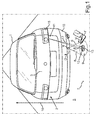
- Fig. 1 shows a motor vehicle 1, which may be, for example, a motor vehicle, especially a passenger car, act. Shown is a rear 2 of the motor vehicle 1.
- the rear 2 may have a flap 3, in particular a tailgate or a trunk lid.
- the following explanations may, however, additionally or alternatively to the flap 3 at the rear 2, also be applied to another flap of the motor vehicle 1, for example a vehicle door or the hood.
- a user can open the flap 3 without contact, by executing, for example, with a foot F a pivoting movement M at the rear 2.
- the pivoting movement M is detected and upon detection of the pivoting movement, the flap 3, for example, opened by a motor.
- This detection of the presence of the foot F may be provided by a sensor device 4 which may be adapted to detect the foot F of the user and / or the pivotal movement M of the foot F outside the motor vehicle 1 in an environment 5.
- the sensor device 4 can for this purpose have a detection area 6 for detecting a presence of the foot F.
- the detection region 6 can be directed, starting from the sensor device 4, onto a bottom surface 7, for example a road. In this way, a gap 8 between the sensor device 4 and a part 9 of the bottom surface 7 detected by the detection region 6 is delimited by the detection region 6, which is suitable for the user holding his foot F in, and thus in the sensor device 4 a triggering or sensor signal D generated.
- This sensor signal D can be used to control, for example, the motorized tailgate 3 in a conventional manner.
- a mark can be provided for the user.
- a lighting device 11 can be provided in the motor vehicle 1.
- the luminous marking 12 can have a luminous core region 13 whose brightness is so large in relation to a luminous edge region 14 surrounding the luminous core region 13 that a predetermined minimum contrast of the luminous core region 13 results in relation to the luminous edge region 14.
- the user can reliably recognize or perceive the luminous core region 13 visually.
- this mark is particularly reliable, even if the motor vehicle 1 is dirty or dirty because it has been driven, for example, by snow or mud.
- the sensor device 4 may have a housing 18, which may be formed, for example, of plastic and / or a material that shields a housing interior 19 against electromagnetic interference radiation.
- a sensor element 20 In the housing 18, that is, in the housing interior 19, a sensor element 20 or it may be more Be arranged sensor elements. In the example shown, only one sensor element 20 is provided for providing the detection area 6.
- the sensor housing 18 is arranged on a first component 10 of the motor vehicle 1.
- the first component 10 may be, for example, a bumper, for example the bumper at the rear 2. This has the advantage that the sensor device 4 has a distance to the bottom surface 7, which is smaller than one meter, in particular smaller than 17 cm, is. In other words, it is ensured that the foot F is reliably detected by the sensor element 20. Too large a distance between the sensor element 20 and the foot F could make the detection unreliable.
- the lighting device 11 may be arranged in another, second component 15, which is different from the component 10.
- the component 15 is arranged higher than the component 10 along a vehicle vertical axis 16 or z-direction. This results in the higher probability that the component 15 has a lower degree of contamination than the component 10.
- the likelihood that light leakage of a light beam 17 emitted or emitted to generate the luminous marking 12 is obstructed or blocked by dirt is reduced.
- the component 15 is preferably a vehicle lamp of the motor vehicle 1, in particular a tail lamp.
- the component 15 may for example have a brake light and / or a reversing light.
- the sensor element 20 may, for example, be an infrared-based motion sensor, an ultrasound sensor, a camera or an optical receiver for ambient brightness.
- sensor signal D can be generated by sensor device 4.
- the sensor device 4 may be coupled to a control device 22, which may be, for example, a control device of the motor vehicle 1.
- the control device 22 may be part of the sensor device 4. Of the sensor device 4, only the housing 18 with the sensor element 20 has to be arranged on the component 10.
- the control device 22 may receive the sensor signal D and, in response to the sensor signal D, actuate a locking system 23, which may be designed, for example, for a motorized tailgate move. In the case of the locking system 23, a control circuit can be provided for this purpose, for example.
- a radio key receiver 24 may also be provided which detects a presence of a radio key in the environment 5, for example in an area closer than 20 meters, in particular closer than 10 meters, to the motor vehicle 1.
- the radio key receiver 24 can likewise be coupled to the control device 22 and emit a presence or presence signal P to the control device 22 when a radio key is detected in the environment 5.
- the control device 22 generates a control signal for the locking system 23 as a function of the sensor signal D only in the presence of a presence signal P.
- the sensor element 20 and the lighting device are activated only in the presence signal P present, so that the light-emitting marker 13 is generated only at present presence signal P on the bottom surface 7 and the sensor device 4 detects an object in the detection area 6.
- the lighting device 11 can be activated by the control device 22, for example.
- the lighting device 11 may be integrated in the component 15, that in particular a vehicle lamp, preferably a tail lamp, is.
- a light source 25 may be provided, which may comprise, for example, a light emitting diode and / or a laser.
- the light source 25 may be designed to generate a functional light of the taillight, for example a tail light, a brake light, a reversing light and / or a fog light. It may also be a light source 25, which may be provided exclusively for generating the luminous marking 13.
- an optical element 26 can be provided as part of the lighting device 11.
- the optical element 26 may be configured to form light 27 radiated from the light source 25 to the light beam 17, which falls on the part 9 of the bottom surface 7 and thereby generates the luminous marking 12.
- the lighting device 11 is integrated in the component 15 and does not have to be arranged in the housing 18, resulting in a particularly small-sized sensor housing for the sensor element 20. Furthermore, this is also the interconnection in the housing 18th and the cooling surface requirement is reduced in an advantageous manner. There is no need to provide circuitry for the light source 25 and optical element 26, nor cooling for these components in the housing 18.
- the lighting unit that is, the lighting device 11 for generating the visible activation point on the bottom surface 7
- a dedicated light source that is, for example, a light emitting diode and driver chips
- the size of the sensor housing 18 can be reduced.
- a cooling surface and further thermal adjustments must be provided in the sensor housing 18, so that both the sensor element 20 and the light source 25 can be provided in one and the same housing.
- the optical element 26 can be used, for example, by an optical waveguide and / or shutter (controllable diaphragm) and / or one or more prisms or for example a mirror as an optical deflection to image the visible activation point, that is to say the luminous marking 12, on the bottom surface 7 .
- the light 27 can also be bundled by a plurality of light sources in the taillight via the optical element 26 so as to set the brightness, that is to say the luminous intensity, lighter or darker, for example as a function of ambient light 5.
- Suitable control signals for controlling the optical element 26, for example motorized pivoting of a mirror can be generated by the control device 22, for example.
- the motor vehicle 1 thus provides a sensor device for a non-contact flap opener, the light exit region 28 of which does not easily contaminate the light beam 17 for generating the illuminated marking 12 and which has a sensor housing for at least one receiver, for example an optical receiver, a camera or an ultrasonic receiver, the compact builds.
- a particularly low-cost and therefore inexpensive sensor device can be provided.
- the lighting device 11 is arranged in another assembly of the motor vehicle 1, namely the component 5, as the sensor housing 18.
- the receiver of the sensor device needs to be housed in the sensor housing, that is, the sensor element 20 or a Arrangement of several sensor elements.
- the lighting device 11 is arranged higher than the sensor housing 18th
- the lighting device 11 is arranged in the region of the tail light of a motor vehicle. It is further preferred that the lighting device 11 is integrated in the tail light. In this case, in particular in the tail light components already existing, such as light sources and / or optics for providing a beam path, for the function of marking the monitored area 8 and 9 are used. Overall, the example shows how the invention allows illumination for tailgate openers out of taillights out.
Landscapes
- Engineering & Computer Science (AREA)
- Mechanical Engineering (AREA)
- Human Computer Interaction (AREA)
- Lighting Device Outwards From Vehicle And Optical Signal (AREA)
Applications Claiming Priority (1)
| Application Number | Priority Date | Filing Date | Title |
|---|---|---|---|
| DE102014116171.8A DE102014116171A1 (de) | 2014-11-06 | 2014-11-06 | Vorrichtung mit Außenbewegungssensor und Leuchtmarkierung für ein Kraftfahrzeug |
Publications (2)
| Publication Number | Publication Date |
|---|---|
| EP3025908A1 true EP3025908A1 (fr) | 2016-06-01 |
| EP3025908B1 EP3025908B1 (fr) | 2020-08-05 |
Family
ID=54427616
Family Applications (1)
| Application Number | Title | Priority Date | Filing Date |
|---|---|---|---|
| EP15192940.3A Active EP3025908B1 (fr) | 2014-11-06 | 2015-11-04 | Dispositif comprenant un capteur de mouvement exterieur et balise lumineuse pour un vehicule automobile |
Country Status (2)
| Country | Link |
|---|---|
| EP (1) | EP3025908B1 (fr) |
| DE (1) | DE102014116171A1 (fr) |
Cited By (8)
| Publication number | Priority date | Publication date | Assignee | Title |
|---|---|---|---|---|
| WO2019110444A1 (fr) * | 2017-12-04 | 2019-06-13 | Witte Automotive Gmbh | Système de capteur optique pour véhicule automobile |
| CN109890658A (zh) * | 2017-01-26 | 2019-06-14 | 宝马股份公司 | 自动化车辆的预期车辆打开前区的显示 |
| WO2019115264A1 (fr) * | 2017-12-13 | 2019-06-20 | HELLA GmbH & Co. KGaA | Véhicule avec une caméra pour détecter une partie du corps d'un utilisateur et procédé de fonctionnement du véhicule |
| EP3530527A1 (fr) * | 2018-02-21 | 2019-08-28 | Huf Hülsbeck & Fürst GmbH & Co. KG | Système de capteur optique d'un véhicule automobile destiné à la détection de gestes de commande |
| WO2019211760A1 (fr) | 2018-04-30 | 2019-11-07 | Tofilescu Pompilian | Hayon élévateur motorisé mains libres basé sur un appareil de prise de vues |
| FR3090078A1 (fr) * | 2018-10-31 | 2020-06-19 | Valeo Vision Belgique | Dispositif de controle d'au moins deux fonctions lumineuses pour vehicule automobile |
| DE102019113953A1 (de) * | 2019-05-24 | 2020-11-26 | HELLA GmbH & Co. KGaA | Fahrzeug mit einer Kamera zur Erfassung eines Körperteils eines Benutzers und Verfahren für den Betrieb des Fahrzeugs |
| EP4021767A4 (fr) * | 2019-08-26 | 2024-01-24 | Beijing Asu Tech Co., Ltd. | Appareil et procédé de commande |
Families Citing this family (3)
| Publication number | Priority date | Publication date | Assignee | Title |
|---|---|---|---|---|
| DE102017222816A1 (de) * | 2017-12-14 | 2019-06-19 | Bayerische Motoren Werke Aktiengesellschaft | Markieren eines einen Erfassungsbereich einer fahrzeugseitigen Umfeldsensorik repräsentierenden Bodenbereichs |
| JP7093648B2 (ja) * | 2018-02-27 | 2022-06-30 | 株式会社ホンダアクセス | 超音波センサの取付構造 |
| CN108860058A (zh) * | 2018-03-28 | 2018-11-23 | 安徽尼古拉电子科技有限公司 | 雷达与后备箱开闭功能结合的系统 |
Citations (7)
| Publication number | Priority date | Publication date | Assignee | Title |
|---|---|---|---|---|
| DE10248650A1 (de) * | 2002-10-18 | 2004-05-06 | Daimlerchrysler Ag | Rangierhilfe für ein Fahrzeug |
| EP1902912A1 (fr) | 2006-09-20 | 2008-03-26 | Hella KG Hueck & Co. | Véhicule automobile doté d'un dispositif de détection |
| DE102011075758A1 (de) * | 2011-05-12 | 2012-11-15 | Robert Bosch Gmbh | Überholvorgangshilfsvorrichtung für Fahrzeuge |
| WO2013037465A1 (fr) | 2011-09-12 | 2013-03-21 | Reime Gerd | Dispositif de mesure optique pour un véhicule et véhicule correspondant |
| DE202014101755U1 (de) * | 2013-04-26 | 2014-07-17 | Ford Global Technologies, Llc | Fahrzeugumfeldbeleuchtungsanordnung, die ein animiertes Bild erzeugt |
| WO2014114439A1 (fr) * | 2013-01-23 | 2014-07-31 | Audi Ag | Véhicule automobile, comprenant plusieurs moyens d'éclairage servant à éclairer les zones situées sur le côté ou à l'arrière du véhicule |
| EP2789504A2 (fr) * | 2013-04-09 | 2014-10-15 | Au-Lite Lighting Inc. | Dispositif d'avertissement et procédé pour véhicules |
Family Cites Families (3)
| Publication number | Priority date | Publication date | Assignee | Title |
|---|---|---|---|---|
| DE102012107288A1 (de) * | 2012-08-08 | 2014-03-06 | Brose Fahrzeugteile Gmbh & Co. Kommanditgesellschaft, Hallstadt | Steuerungsverfahren und Steuerungssystem für ein Fahrzeugschließelement |
| DE102012025490A1 (de) * | 2012-12-24 | 2014-06-26 | Brose Fahrzeugteile Gmbh & Co. Kommanditgesellschaft, Hallstadt | Sensorbaugruppe für ein Kraftfahrzeug |
| CN111994037A (zh) * | 2014-03-26 | 2020-11-27 | 麦格纳车镜美国有限公司 | 使用投射图标的车辆功能控制系统 |
-
2014
- 2014-11-06 DE DE102014116171.8A patent/DE102014116171A1/de not_active Withdrawn
-
2015
- 2015-11-04 EP EP15192940.3A patent/EP3025908B1/fr active Active
Patent Citations (7)
| Publication number | Priority date | Publication date | Assignee | Title |
|---|---|---|---|---|
| DE10248650A1 (de) * | 2002-10-18 | 2004-05-06 | Daimlerchrysler Ag | Rangierhilfe für ein Fahrzeug |
| EP1902912A1 (fr) | 2006-09-20 | 2008-03-26 | Hella KG Hueck & Co. | Véhicule automobile doté d'un dispositif de détection |
| DE102011075758A1 (de) * | 2011-05-12 | 2012-11-15 | Robert Bosch Gmbh | Überholvorgangshilfsvorrichtung für Fahrzeuge |
| WO2013037465A1 (fr) | 2011-09-12 | 2013-03-21 | Reime Gerd | Dispositif de mesure optique pour un véhicule et véhicule correspondant |
| WO2014114439A1 (fr) * | 2013-01-23 | 2014-07-31 | Audi Ag | Véhicule automobile, comprenant plusieurs moyens d'éclairage servant à éclairer les zones situées sur le côté ou à l'arrière du véhicule |
| EP2789504A2 (fr) * | 2013-04-09 | 2014-10-15 | Au-Lite Lighting Inc. | Dispositif d'avertissement et procédé pour véhicules |
| DE202014101755U1 (de) * | 2013-04-26 | 2014-07-17 | Ford Global Technologies, Llc | Fahrzeugumfeldbeleuchtungsanordnung, die ein animiertes Bild erzeugt |
Cited By (13)
| Publication number | Priority date | Publication date | Assignee | Title |
|---|---|---|---|---|
| CN109890658A (zh) * | 2017-01-26 | 2019-06-14 | 宝马股份公司 | 自动化车辆的预期车辆打开前区的显示 |
| CN109890658B (zh) * | 2017-01-26 | 2022-09-27 | 宝马股份公司 | 自动化车辆的预期车辆打开前区的显示 |
| WO2019110444A1 (fr) * | 2017-12-04 | 2019-06-13 | Witte Automotive Gmbh | Système de capteur optique pour véhicule automobile |
| DE102017128774B4 (de) | 2017-12-04 | 2023-11-02 | Witte Automotive Gmbh | Optisches Sensorsystem für ein Kraftfahrzeug |
| US11364917B2 (en) | 2017-12-13 | 2022-06-21 | HELLA GmbH & Co. KGaA | Vehicle having a camera for detecting a body part of a user and method for the operation of the vehicle |
| WO2019115264A1 (fr) * | 2017-12-13 | 2019-06-20 | HELLA GmbH & Co. KGaA | Véhicule avec une caméra pour détecter une partie du corps d'un utilisateur et procédé de fonctionnement du véhicule |
| EP3530527A1 (fr) * | 2018-02-21 | 2019-08-28 | Huf Hülsbeck & Fürst GmbH & Co. KG | Système de capteur optique d'un véhicule automobile destiné à la détection de gestes de commande |
| EP3775461A4 (fr) * | 2018-04-30 | 2021-12-29 | Tofilescu, Pompilian | Hayon élévateur motorisé mains libres basé sur un appareil de prise de vues |
| WO2019211760A1 (fr) | 2018-04-30 | 2019-11-07 | Tofilescu Pompilian | Hayon élévateur motorisé mains libres basé sur un appareil de prise de vues |
| US10814779B2 (en) | 2018-10-31 | 2020-10-27 | Valeo Vision Belgique | Device for managing at least two light functions for a motor vehicle |
| FR3090078A1 (fr) * | 2018-10-31 | 2020-06-19 | Valeo Vision Belgique | Dispositif de controle d'au moins deux fonctions lumineuses pour vehicule automobile |
| DE102019113953A1 (de) * | 2019-05-24 | 2020-11-26 | HELLA GmbH & Co. KGaA | Fahrzeug mit einer Kamera zur Erfassung eines Körperteils eines Benutzers und Verfahren für den Betrieb des Fahrzeugs |
| EP4021767A4 (fr) * | 2019-08-26 | 2024-01-24 | Beijing Asu Tech Co., Ltd. | Appareil et procédé de commande |
Also Published As
| Publication number | Publication date |
|---|---|
| DE102014116171A1 (de) | 2016-05-12 |
| EP3025908B1 (fr) | 2020-08-05 |
Similar Documents
| Publication | Publication Date | Title |
|---|---|---|
| EP3025908B1 (fr) | Dispositif comprenant un capteur de mouvement exterieur et balise lumineuse pour un vehicule automobile | |
| EP3099542B1 (fr) | Logo pour véhicule à moteur comportant un système capteur, et procédé correspondant | |
| DE102008002086B4 (de) | Fahrzeugabbildungssystem und Fahrzeugsteuerungsgerät | |
| EP2972480B1 (fr) | Dispositif de protection anti-collision pour un hayon pivotant d'un véhicule automobile, hayon, véhicule automobile et procédé correspondant | |
| DE10010434B4 (de) | Kameravorrichtung und Bremswarnleuchte | |
| DE19755008A1 (de) | Multifunktionaler Innenspiegel | |
| DE102009051485A1 (de) | Verfahren und Vorrichtung zur Steuerung eines Fahrlichts eines Fahrzeugs | |
| DE102014101208A1 (de) | Montagemodul | |
| DE102007036081A1 (de) | Beleuchtungseinrichtung für ein Kraftfahrzeug und Verfahren zur Steuerung einer Leuchte | |
| WO2005029125A1 (fr) | Procede pour ameliorer la visibilite dans un vehicule automobile | |
| DE102017218683A1 (de) | Fahrzeugbasiertes Lidar-System | |
| DE4306026A1 (de) | Schleppfahrzeug für Flugzeuge | |
| DE19936357A1 (de) | Beleuchtungsvorrichtung für ein Kraftfahrzeug | |
| DE102015109932A1 (de) | Warnvorrichtung für ein Kraftfahrzeug mit außen angeordneter Anzeigeeinrichtung sowie Kraftfahrzeug | |
| DE102016004259A1 (de) | Einparkunterstützungssystem | |
| DE102017007761A1 (de) | Vorrichtung zur kamerabasierten Umgebungserfassung für ein Fahrzeug und Steuerungsverfahren hierfür | |
| DE10248650B4 (de) | Rangierhilfe für ein Fahrzeug | |
| DE102011112715A1 (de) | Verfahren zum Erfassen eines Objekts in einem Umfeld eines Kraftfahrzeugs | |
| DE102021000724B3 (de) | Mikrolinsenarray-Projektionsvorrichtung, Beleuchtungsvorrichtung und Fahrzeug | |
| DE102007000371A1 (de) | Fahrzeugbeleuchtungssystem zum Ermöglichen eines Wahrnehmens eines Vorhandenseins eines Fahrzeugs bezüglich dessen Seitenrichtung | |
| WO2015081934A1 (fr) | Éclairage destiné à détecter des gouttes de pluie sur une vitre au moyen d'une caméra | |
| DE60305048T2 (de) | Einrichtung zur erkennung des überfahrens einer strassenmarkierung für ein kraftfahrzeug | |
| DE102015114632A1 (de) | Signalleuchte für Fahrzeuge | |
| EP3077256A1 (fr) | Éclairage destiné à détecter des gouttes de pluie sur une vitre au moyen d'une caméra | |
| DE102017101130A1 (de) | Kraftfahrzeugscheinwerfer, Scheinwerferanordnung mit mindestens zwei solcher Scheinwerfer und Verfahren zum Betrieb einer solchen Scheinwerferanordnung |
Legal Events
| Date | Code | Title | Description |
|---|---|---|---|
| PUAI | Public reference made under article 153(3) epc to a published international application that has entered the european phase |
Free format text: ORIGINAL CODE: 0009012 |
|
| AK | Designated contracting states |
Kind code of ref document: A1 Designated state(s): AL AT BE BG CH CY CZ DE DK EE ES FI FR GB GR HR HU IE IS IT LI LT LU LV MC MK MT NL NO PL PT RO RS SE SI SK SM TR |
|
| AX | Request for extension of the european patent |
Extension state: BA ME |
|
| STAA | Information on the status of an ep patent application or granted ep patent |
Free format text: STATUS: REQUEST FOR EXAMINATION WAS MADE |
|
| 17P | Request for examination filed |
Effective date: 20161201 |
|
| RBV | Designated contracting states (corrected) |
Designated state(s): AL AT BE BG CH CY CZ DE DK EE ES FI FR GB GR HR HU IE IS IT LI LT LU LV MC MK MT NL NO PL PT RO RS SE SI SK SM TR |
|
| R17P | Request for examination filed (corrected) |
Effective date: 20161201 |
|
| STAA | Information on the status of an ep patent application or granted ep patent |
Free format text: STATUS: EXAMINATION IS IN PROGRESS |
|
| 17Q | First examination report despatched |
Effective date: 20171220 |
|
| GRAP | Despatch of communication of intention to grant a patent |
Free format text: ORIGINAL CODE: EPIDOSNIGR1 |
|
| STAA | Information on the status of an ep patent application or granted ep patent |
Free format text: STATUS: GRANT OF PATENT IS INTENDED |
|
| INTG | Intention to grant announced |
Effective date: 20200305 |
|
| GRAS | Grant fee paid |
Free format text: ORIGINAL CODE: EPIDOSNIGR3 |
|
| GRAA | (expected) grant |
Free format text: ORIGINAL CODE: 0009210 |
|
| STAA | Information on the status of an ep patent application or granted ep patent |
Free format text: STATUS: THE PATENT HAS BEEN GRANTED |
|
| AK | Designated contracting states |
Kind code of ref document: B1 Designated state(s): AL AT BE BG CH CY CZ DE DK EE ES FI FR GB GR HR HU IE IS IT LI LT LU LV MC MK MT NL NO PL PT RO RS SE SI SK SM TR |
|
| REG | Reference to a national code |
Ref country code: GB Ref legal event code: FG4D Free format text: NOT ENGLISH |
|
| REG | Reference to a national code |
Ref country code: CH Ref legal event code: EP |
|
| REG | Reference to a national code |
Ref country code: AT Ref legal event code: REF Ref document number: 1298280 Country of ref document: AT Kind code of ref document: T Effective date: 20200815 |
|
| REG | Reference to a national code |
Ref country code: DE Ref legal event code: R096 Ref document number: 502015013159 Country of ref document: DE |
|
| REG | Reference to a national code |
Ref country code: IE Ref legal event code: FG4D Free format text: LANGUAGE OF EP DOCUMENT: GERMAN |
|
| REG | Reference to a national code |
Ref country code: LT Ref legal event code: MG4D |
|
| REG | Reference to a national code |
Ref country code: NL Ref legal event code: MP Effective date: 20200805 |
|
| PG25 | Lapsed in a contracting state [announced via postgrant information from national office to epo] |
Ref country code: LT Free format text: LAPSE BECAUSE OF FAILURE TO SUBMIT A TRANSLATION OF THE DESCRIPTION OR TO PAY THE FEE WITHIN THE PRESCRIBED TIME-LIMIT Effective date: 20200805 Ref country code: HR Free format text: LAPSE BECAUSE OF FAILURE TO SUBMIT A TRANSLATION OF THE DESCRIPTION OR TO PAY THE FEE WITHIN THE PRESCRIBED TIME-LIMIT Effective date: 20200805 Ref country code: GR Free format text: LAPSE BECAUSE OF FAILURE TO SUBMIT A TRANSLATION OF THE DESCRIPTION OR TO PAY THE FEE WITHIN THE PRESCRIBED TIME-LIMIT Effective date: 20201106 Ref country code: NO Free format text: LAPSE BECAUSE OF FAILURE TO SUBMIT A TRANSLATION OF THE DESCRIPTION OR TO PAY THE FEE WITHIN THE PRESCRIBED TIME-LIMIT Effective date: 20201105 Ref country code: ES Free format text: LAPSE BECAUSE OF FAILURE TO SUBMIT A TRANSLATION OF THE DESCRIPTION OR TO PAY THE FEE WITHIN THE PRESCRIBED TIME-LIMIT Effective date: 20200805 Ref country code: BG Free format text: LAPSE BECAUSE OF FAILURE TO SUBMIT A TRANSLATION OF THE DESCRIPTION OR TO PAY THE FEE WITHIN THE PRESCRIBED TIME-LIMIT Effective date: 20201105 Ref country code: PT Free format text: LAPSE BECAUSE OF FAILURE TO SUBMIT A TRANSLATION OF THE DESCRIPTION OR TO PAY THE FEE WITHIN THE PRESCRIBED TIME-LIMIT Effective date: 20201207 Ref country code: FI Free format text: LAPSE BECAUSE OF FAILURE TO SUBMIT A TRANSLATION OF THE DESCRIPTION OR TO PAY THE FEE WITHIN THE PRESCRIBED TIME-LIMIT Effective date: 20200805 Ref country code: SE Free format text: LAPSE BECAUSE OF FAILURE TO SUBMIT A TRANSLATION OF THE DESCRIPTION OR TO PAY THE FEE WITHIN THE PRESCRIBED TIME-LIMIT Effective date: 20200805 |
|
| PG25 | Lapsed in a contracting state [announced via postgrant information from national office to epo] |
Ref country code: LV Free format text: LAPSE BECAUSE OF FAILURE TO SUBMIT A TRANSLATION OF THE DESCRIPTION OR TO PAY THE FEE WITHIN THE PRESCRIBED TIME-LIMIT Effective date: 20200805 Ref country code: RS Free format text: LAPSE BECAUSE OF FAILURE TO SUBMIT A TRANSLATION OF THE DESCRIPTION OR TO PAY THE FEE WITHIN THE PRESCRIBED TIME-LIMIT Effective date: 20200805 Ref country code: PL Free format text: LAPSE BECAUSE OF FAILURE TO SUBMIT A TRANSLATION OF THE DESCRIPTION OR TO PAY THE FEE WITHIN THE PRESCRIBED TIME-LIMIT Effective date: 20200805 Ref country code: NL Free format text: LAPSE BECAUSE OF FAILURE TO SUBMIT A TRANSLATION OF THE DESCRIPTION OR TO PAY THE FEE WITHIN THE PRESCRIBED TIME-LIMIT Effective date: 20200805 Ref country code: IS Free format text: LAPSE BECAUSE OF FAILURE TO SUBMIT A TRANSLATION OF THE DESCRIPTION OR TO PAY THE FEE WITHIN THE PRESCRIBED TIME-LIMIT Effective date: 20201205 |
|
| PG25 | Lapsed in a contracting state [announced via postgrant information from national office to epo] |
Ref country code: RO Free format text: LAPSE BECAUSE OF FAILURE TO SUBMIT A TRANSLATION OF THE DESCRIPTION OR TO PAY THE FEE WITHIN THE PRESCRIBED TIME-LIMIT Effective date: 20200805 Ref country code: SM Free format text: LAPSE BECAUSE OF FAILURE TO SUBMIT A TRANSLATION OF THE DESCRIPTION OR TO PAY THE FEE WITHIN THE PRESCRIBED TIME-LIMIT Effective date: 20200805 Ref country code: EE Free format text: LAPSE BECAUSE OF FAILURE TO SUBMIT A TRANSLATION OF THE DESCRIPTION OR TO PAY THE FEE WITHIN THE PRESCRIBED TIME-LIMIT Effective date: 20200805 Ref country code: DK Free format text: LAPSE BECAUSE OF FAILURE TO SUBMIT A TRANSLATION OF THE DESCRIPTION OR TO PAY THE FEE WITHIN THE PRESCRIBED TIME-LIMIT Effective date: 20200805 Ref country code: CZ Free format text: LAPSE BECAUSE OF FAILURE TO SUBMIT A TRANSLATION OF THE DESCRIPTION OR TO PAY THE FEE WITHIN THE PRESCRIBED TIME-LIMIT Effective date: 20200805 |
|
| REG | Reference to a national code |
Ref country code: DE Ref legal event code: R097 Ref document number: 502015013159 Country of ref document: DE |
|
| PG25 | Lapsed in a contracting state [announced via postgrant information from national office to epo] |
Ref country code: AL Free format text: LAPSE BECAUSE OF FAILURE TO SUBMIT A TRANSLATION OF THE DESCRIPTION OR TO PAY THE FEE WITHIN THE PRESCRIBED TIME-LIMIT Effective date: 20200805 |
|
| PLBE | No opposition filed within time limit |
Free format text: ORIGINAL CODE: 0009261 |
|
| STAA | Information on the status of an ep patent application or granted ep patent |
Free format text: STATUS: NO OPPOSITION FILED WITHIN TIME LIMIT |
|
| PG25 | Lapsed in a contracting state [announced via postgrant information from national office to epo] |
Ref country code: MC Free format text: LAPSE BECAUSE OF FAILURE TO SUBMIT A TRANSLATION OF THE DESCRIPTION OR TO PAY THE FEE WITHIN THE PRESCRIBED TIME-LIMIT Effective date: 20200805 Ref country code: SK Free format text: LAPSE BECAUSE OF FAILURE TO SUBMIT A TRANSLATION OF THE DESCRIPTION OR TO PAY THE FEE WITHIN THE PRESCRIBED TIME-LIMIT Effective date: 20200805 |
|
| REG | Reference to a national code |
Ref country code: CH Ref legal event code: PL |
|
| 26N | No opposition filed |
Effective date: 20210507 |
|
| PG25 | Lapsed in a contracting state [announced via postgrant information from national office to epo] |
Ref country code: LU Free format text: LAPSE BECAUSE OF NON-PAYMENT OF DUE FEES Effective date: 20201104 Ref country code: IT Free format text: LAPSE BECAUSE OF FAILURE TO SUBMIT A TRANSLATION OF THE DESCRIPTION OR TO PAY THE FEE WITHIN THE PRESCRIBED TIME-LIMIT Effective date: 20200805 |
|
| REG | Reference to a national code |
Ref country code: BE Ref legal event code: MM Effective date: 20201130 |
|
| PG25 | Lapsed in a contracting state [announced via postgrant information from national office to epo] |
Ref country code: SI Free format text: LAPSE BECAUSE OF FAILURE TO SUBMIT A TRANSLATION OF THE DESCRIPTION OR TO PAY THE FEE WITHIN THE PRESCRIBED TIME-LIMIT Effective date: 20200805 Ref country code: LI Free format text: LAPSE BECAUSE OF NON-PAYMENT OF DUE FEES Effective date: 20201130 Ref country code: CH Free format text: LAPSE BECAUSE OF NON-PAYMENT OF DUE FEES Effective date: 20201130 |
|
| PG25 | Lapsed in a contracting state [announced via postgrant information from national office to epo] |
Ref country code: IE Free format text: LAPSE BECAUSE OF NON-PAYMENT OF DUE FEES Effective date: 20201104 |
|
| REG | Reference to a national code |
Ref country code: AT Ref legal event code: MM01 Ref document number: 1298280 Country of ref document: AT Kind code of ref document: T Effective date: 20201104 |
|
| PG25 | Lapsed in a contracting state [announced via postgrant information from national office to epo] |
Ref country code: AT Free format text: LAPSE BECAUSE OF NON-PAYMENT OF DUE FEES Effective date: 20201104 |
|
| PG25 | Lapsed in a contracting state [announced via postgrant information from national office to epo] |
Ref country code: TR Free format text: LAPSE BECAUSE OF FAILURE TO SUBMIT A TRANSLATION OF THE DESCRIPTION OR TO PAY THE FEE WITHIN THE PRESCRIBED TIME-LIMIT Effective date: 20200805 Ref country code: MT Free format text: LAPSE BECAUSE OF FAILURE TO SUBMIT A TRANSLATION OF THE DESCRIPTION OR TO PAY THE FEE WITHIN THE PRESCRIBED TIME-LIMIT Effective date: 20200805 Ref country code: CY Free format text: LAPSE BECAUSE OF FAILURE TO SUBMIT A TRANSLATION OF THE DESCRIPTION OR TO PAY THE FEE WITHIN THE PRESCRIBED TIME-LIMIT Effective date: 20200805 |
|
| PG25 | Lapsed in a contracting state [announced via postgrant information from national office to epo] |
Ref country code: MK Free format text: LAPSE BECAUSE OF FAILURE TO SUBMIT A TRANSLATION OF THE DESCRIPTION OR TO PAY THE FEE WITHIN THE PRESCRIBED TIME-LIMIT Effective date: 20200805 |
|
| PG25 | Lapsed in a contracting state [announced via postgrant information from national office to epo] |
Ref country code: BE Free format text: LAPSE BECAUSE OF NON-PAYMENT OF DUE FEES Effective date: 20201130 |
|
| P01 | Opt-out of the competence of the unified patent court (upc) registered |
Effective date: 20230528 |
|
| PGFP | Annual fee paid to national office [announced via postgrant information from national office to epo] |
Ref country code: GB Payment date: 20231120 Year of fee payment: 9 |
|
| PGFP | Annual fee paid to national office [announced via postgrant information from national office to epo] |
Ref country code: FR Payment date: 20231124 Year of fee payment: 9 Ref country code: DE Payment date: 20231107 Year of fee payment: 9 |