EP3025908A1 - Device with external movement sensor and illuminated marking for a motor vehicle - Google Patents
Device with external movement sensor and illuminated marking for a motor vehicle Download PDFInfo
- Publication number
- EP3025908A1 EP3025908A1 EP15192940.3A EP15192940A EP3025908A1 EP 3025908 A1 EP3025908 A1 EP 3025908A1 EP 15192940 A EP15192940 A EP 15192940A EP 3025908 A1 EP3025908 A1 EP 3025908A1
- Authority
- EP
- European Patent Office
- Prior art keywords
- motor vehicle
- light
- sensor
- designed
- luminous
- Prior art date
- Legal status (The legal status is an assumption and is not a legal conclusion. Google has not performed a legal analysis and makes no representation as to the accuracy of the status listed.)
- Granted
Links
- 230000033001 locomotion Effects 0.000 title description 12
- 238000001514 detection method Methods 0.000 claims abstract description 34
- 238000009434 installation Methods 0.000 claims abstract description 14
- 230000001419 dependent effect Effects 0.000 claims abstract description 5
- 230000003287 optical effect Effects 0.000 claims description 29
- 230000007935 neutral effect Effects 0.000 claims description 3
- 230000005855 radiation Effects 0.000 claims description 3
- 239000003550 marker Substances 0.000 claims description 2
- 230000008901 benefit Effects 0.000 description 18
- 238000011161 development Methods 0.000 description 7
- 230000018109 developmental process Effects 0.000 description 7
- 230000008878 coupling Effects 0.000 description 4
- 238000010168 coupling process Methods 0.000 description 4
- 238000005859 coupling reaction Methods 0.000 description 4
- 238000001816 cooling Methods 0.000 description 3
- 238000005286 illumination Methods 0.000 description 3
- 230000004913 activation Effects 0.000 description 2
- 238000011109 contamination Methods 0.000 description 2
- 239000000463 material Substances 0.000 description 2
- 230000004044 response Effects 0.000 description 2
- 239000000853 adhesive Substances 0.000 description 1
- 230000001070 adhesive effect Effects 0.000 description 1
- -1 dirt Substances 0.000 description 1
- 230000009977 dual effect Effects 0.000 description 1
- 239000000428 dust Substances 0.000 description 1
- 230000001771 impaired effect Effects 0.000 description 1
- 238000001746 injection moulding Methods 0.000 description 1
- 230000010354 integration Effects 0.000 description 1
- 238000002604 ultrasonography Methods 0.000 description 1
Images

Classifications
-
- B—PERFORMING OPERATIONS; TRANSPORTING
- B60—VEHICLES IN GENERAL
- B60R—VEHICLES, VEHICLE FITTINGS, OR VEHICLE PARTS, NOT OTHERWISE PROVIDED FOR
- B60R25/00—Fittings or systems for preventing or indicating unauthorised use or theft of vehicles
- B60R25/20—Means to switch the anti-theft system on or off
- B60R25/2054—Means to switch the anti-theft system on or off by foot gestures
-
- B—PERFORMING OPERATIONS; TRANSPORTING
- B60—VEHICLES IN GENERAL
- B60Q—ARRANGEMENT OF SIGNALLING OR LIGHTING DEVICES, THE MOUNTING OR SUPPORTING THEREOF OR CIRCUITS THEREFOR, FOR VEHICLES IN GENERAL
- B60Q1/00—Arrangement of optical signalling or lighting devices, the mounting or supporting thereof or circuits therefor
- B60Q1/26—Arrangement of optical signalling or lighting devices, the mounting or supporting thereof or circuits therefor the devices being primarily intended to indicate the vehicle, or parts thereof, or to give signals, to other traffic
- B60Q1/2607—Arrangement of optical signalling or lighting devices, the mounting or supporting thereof or circuits therefor the devices being primarily intended to indicate the vehicle, or parts thereof, or to give signals, to other traffic comprising at least two indicating lamps
-
- B—PERFORMING OPERATIONS; TRANSPORTING
- B60—VEHICLES IN GENERAL
- B60Q—ARRANGEMENT OF SIGNALLING OR LIGHTING DEVICES, THE MOUNTING OR SUPPORTING THEREOF OR CIRCUITS THEREFOR, FOR VEHICLES IN GENERAL
- B60Q1/00—Arrangement of optical signalling or lighting devices, the mounting or supporting thereof or circuits therefor
- B60Q1/26—Arrangement of optical signalling or lighting devices, the mounting or supporting thereof or circuits therefor the devices being primarily intended to indicate the vehicle, or parts thereof, or to give signals, to other traffic
- B60Q1/2661—Arrangement of optical signalling or lighting devices, the mounting or supporting thereof or circuits therefor the devices being primarily intended to indicate the vehicle, or parts thereof, or to give signals, to other traffic mounted on parts having other functions
- B60Q1/2669—Arrangement of optical signalling or lighting devices, the mounting or supporting thereof or circuits therefor the devices being primarily intended to indicate the vehicle, or parts thereof, or to give signals, to other traffic mounted on parts having other functions on door or boot handles
-
- B—PERFORMING OPERATIONS; TRANSPORTING
- B60—VEHICLES IN GENERAL
- B60Q—ARRANGEMENT OF SIGNALLING OR LIGHTING DEVICES, THE MOUNTING OR SUPPORTING THEREOF OR CIRCUITS THEREFOR, FOR VEHICLES IN GENERAL
- B60Q1/00—Arrangement of optical signalling or lighting devices, the mounting or supporting thereof or circuits therefor
- B60Q1/26—Arrangement of optical signalling or lighting devices, the mounting or supporting thereof or circuits therefor the devices being primarily intended to indicate the vehicle, or parts thereof, or to give signals, to other traffic
- B60Q1/32—Arrangement of optical signalling or lighting devices, the mounting or supporting thereof or circuits therefor the devices being primarily intended to indicate the vehicle, or parts thereof, or to give signals, to other traffic for indicating vehicle sides, e.g. clearance lights
- B60Q1/323—Arrangement of optical signalling or lighting devices, the mounting or supporting thereof or circuits therefor the devices being primarily intended to indicate the vehicle, or parts thereof, or to give signals, to other traffic for indicating vehicle sides, e.g. clearance lights on or for doors
-
- E—FIXED CONSTRUCTIONS
- E05—LOCKS; KEYS; WINDOW OR DOOR FITTINGS; SAFES
- E05F—DEVICES FOR MOVING WINGS INTO OPEN OR CLOSED POSITION; CHECKS FOR WINGS; WING FITTINGS NOT OTHERWISE PROVIDED FOR, CONCERNED WITH THE FUNCTIONING OF THE WING
- E05F15/00—Power-operated mechanisms for wings
- E05F15/70—Power-operated mechanisms for wings with automatic actuation
- E05F15/73—Power-operated mechanisms for wings with automatic actuation responsive to movement or presence of persons or objects
-
- B—PERFORMING OPERATIONS; TRANSPORTING
- B60—VEHICLES IN GENERAL
- B60Q—ARRANGEMENT OF SIGNALLING OR LIGHTING DEVICES, THE MOUNTING OR SUPPORTING THEREOF OR CIRCUITS THEREFOR, FOR VEHICLES IN GENERAL
- B60Q2400/00—Special features or arrangements of exterior signal lamps for vehicles
- B60Q2400/50—Projected symbol or information, e.g. onto the road or car body
-
- E—FIXED CONSTRUCTIONS
- E05—LOCKS; KEYS; WINDOW OR DOOR FITTINGS; SAFES
- E05Y—INDEXING SCHEME RELATING TO HINGES OR OTHER SUSPENSION DEVICES FOR DOORS, WINDOWS OR WINGS AND DEVICES FOR MOVING WINGS INTO OPEN OR CLOSED POSITION, CHECKS FOR WINGS AND WING FITTINGS NOT OTHERWISE PROVIDED FOR, CONCERNED WITH THE FUNCTIONING OF THE WING
- E05Y2400/00—Electronic control; Power supply; Power or signal transmission; User interfaces
- E05Y2400/80—User interfaces
- E05Y2400/85—User input means
- E05Y2400/852—Sensors
- E05Y2400/856—Actuation thereof
- E05Y2400/858—Actuation thereof by body parts
-
- E—FIXED CONSTRUCTIONS
- E05—LOCKS; KEYS; WINDOW OR DOOR FITTINGS; SAFES
- E05Y—INDEXING SCHEME RELATING TO HINGES OR OTHER SUSPENSION DEVICES FOR DOORS, WINDOWS OR WINGS AND DEVICES FOR MOVING WINGS INTO OPEN OR CLOSED POSITION, CHECKS FOR WINGS AND WING FITTINGS NOT OTHERWISE PROVIDED FOR, CONCERNED WITH THE FUNCTIONING OF THE WING
- E05Y2900/00—Application of doors, windows, wings or fittings thereof
- E05Y2900/50—Application of doors, windows, wings or fittings thereof for vehicles
- E05Y2900/53—Application of doors, windows, wings or fittings thereof for vehicles characterised by the type of wing
- E05Y2900/546—Tailgates
Definitions
- the invention relates to a device for a motor vehicle with a sensor device for detecting an object, in particular a body part, in a detection area outside the motor vehicle and with a lighting device for marking the detection area.
- the invention also includes a vehicle lamp and a motor vehicle.
- a device of the type mentioned is for example from the EP 1 902 912 A1 known. Thereafter, the device comprises a sensor device which monitors for the presence of a body part of a user or an object in an outer area of a motor vehicle and when recognizing a body movement of a leg or foot next to the motor vehicle opens the tailgate or boot lid of the motor vehicle. It may be provided a marking means, for example, generates a point of light on the ground.
- a motion detector for a motor vehicle which radiates modulated light on a floor surface in an environment of the motor vehicle. Two different areas on the floor are illuminated. If a user disturbs one of the illuminated areas with his foot, this is detected as movement and a tailgate of the motor vehicle is opened.
- optical tailgate openers has been recognized as a disadvantage that when pollution of the lighting device, which is to project the luminous marking on the floor surface, this luminous marking is no longer recognizable by the user. Then the user does not know where to pivot with his foot in order to trigger the opening of the tailgate.
- the invention is based on the object, in a motor vehicle with vehicle-external detection area for detecting a presence of an object, in particular a body part, to mark the detection area for the user reliably.
- a device for a motor vehicle which has a sensor device and a lighting device.
- the sensor device has a sensor housing or housing for short, which can be fastened or arranged in a predetermined first installation position on a first component of the motor vehicle.
- the housing may be e.g. a flange for screwing or an adhesive surface for adhering to the first component.
- at least one sensor element is arranged, which in the intended first installation position of the housing has a to a bottom surface of an environment of the motor vehicle, in particular to a road, extending detection area and is designed to one of a presence of an object, in particular a Body part of a user to generate in the detection area dependent sensor signal.
- the detection range of the at least one sensor element downwards, when the housing is arranged as intended in the first installation position in the motor vehicle. It can be provided here that the presence of the object and / or a movement of the object is signaled.
- the lighting device is designed to generate a light spot or a luminous marking by emitting light in a region of the floor area covered by the detection area.
- the luminous marking is smaller than the area on the bottom surface, which is detected or covered by the detection area of the at least one sensor element. In other words, at least one light beam of the light then penetrates the detection area.
- the lighting device can illuminate into the detection area.
- the lighting device is arranged outside the housing of the sensor device.
- the housing and the lighting device are provided prior to installation in the motor vehicle as two individual components that can be positioned or arranged independently of one another in the motor vehicle.
- the lighting device is designed to be arrangeable in one of the first component, on which the housing is arranged, different second component of the motor vehicle.
- the lighting device may be arranged in a region of the second component, ie on the second component.
- the invention provides a motor vehicle in which an embodiment of the device according to the invention is provided.
- the lighting device can be arranged independently of the sensor device in or on a second component of the motor vehicle. This makes it possible in an advantageous manner to attach the sensor device to a first component, from where the sensing of the presence of the object can be carried out particularly reliably, for example, close to the bottom surface.
- the sensor device in the motor vehicle according to the invention at a distance of at most 80 cm, in particular at most 60 cm, arranged away from the bottom surface.
- the lighting device can be arranged on or in the second component, which can be selected such that it is a component which is less likely to be contaminated or concealed than the first component. This ensures that the light emission from the lighting device to the bottom surface is not affected by adhering to the second component dirt.
- the lighting device is designed to be arrangeable in a second installation position in the motor vehicle, wherein the second mounting position along a vehicle vertical axis of the motor vehicle arranged higher than the first intended installation position of the housing.
- the lighting device is preferably arranged above the sensor device in the motor vehicle according to the invention, wherein above also includes obliquely above.
- the first component is arranged closer to the bottom surface than the second component.
- An installation height of the lighting device is preferably at least 60 cm, in particular at least 80 cm. This results in the advantage that the lighting device is covered with a lower probability of, for example, when driving thrown up material, such as dirt, dust, snow and / or mud.
- the housing is configured fastened to a bumper or a footboard or a tailgate.
- the sensor device By arranging the sensor device on the bumper or running board, there is the advantage that the sensor device is located at a distance of at most 80 cm, in particular at most 60 cm from the bottom surface. As a result, the detection of the object is particularly reliable.
- the arrangement on the tailgate has the advantage that, for example, a reversing camera can be used as a sensor element.
- the provision of the sensor device in the running board has the advantage that motion detection in the area of a driver's door or another vehicle door is made possible.
- the at least one sensor element of the sensor device in each case has an optical receiver, in particular a photosensitive sensor, or a camera or an ultrasonic sensor.
- An optical receiver can be provided with particularly low technical effort.
- a camera can advantageously be fed to a dual function. For example, a reversing camera can be used, which can be used by the driver during rearward travel of the motor vehicle to view the rear area. The camera can be arranged in particular in the manner described in a tailgate of the motor vehicle.
- An ultrasonic sensor has the advantage that a detection of an object in the detection area is possible even when the soiled first component through a dirt layer.
- the lighting device is coupled to a brightness sensor which is designed to generate a brightness signal correlating with an ambient brightness.
- a brightness sensor can be provided in a motor vehicle, for example, for switching between daytime running lights and low beam.
- the brightness sensor can also be realized for example by means of a camera of the motor vehicle.
- the lighting device is designed to set a radiation intensity of the light emitted for generating the luminous marking as a function of the brightness signal of the brightness sensor. This results in the advantage that, depending on the ambient light, a luminous marking recognizable by the user through a predetermined minimum contrast can be generated on the floor surface.
- the sensor device is designed to be coupled to a locking system of the motor vehicle and a control device of the sensor device is adapted to unlock depending on the sensor signal of the at least one sensor element by emitting a control signal to the locking system a flap of the motor vehicle, in particular a tailgate and / or open.
- a corresponding actuator or motor can be provided to open the tailgate.
- the already described optical tailgate opener can be provided in an advantageous manner.
- an electrical interface in particular a plug or a socket or a bus coupling unit.
- the lighting device is designed to generate the illuminated marking only when the motor vehicle is at a standstill and / or switched off and / or locked and / or activated sensor device. This results in the advantage that the luminous marking unnecessarily confuses or irritates anyone in the operation of the motor vehicle.
- the lighting device and the sensor device can be coupled to a radio key receiver of the motor vehicle.
- the device is designed to switch the sensor device and the lighting device from an off state to an active state in response to a radio signal of a radio key, in which the sensor device performs the detection and the lighting device generates the light marking.
- the lighting device in or on a vehicle lamp, in particular a tail light, arranged configured.
- the lighting device is integrated in a vehicle lamp, i. the vehicle lamp is part of this embodiment of the device according to the invention.
- the lighting device is arranged in a component which is substantially free from contamination during normal operation of the motor vehicle.
- the vehicle light can also be a side indicator. This results in the advantage that a motion detection for a driver's door or another vehicle door is possible.
- the lighting device is designed to activate at least one light-emitting diode and / or at least one laser of the vehicle light for generating the light.
- the light emitting diode and / or the laser are each a light source for generating a low beam, a high beam, a brake light, a reversing light, a tail light, a direction indicator light, that is one Flashing light, a fog light and / or a daytime running light.
- a light source is used in this development for generating the luminous marking, which is provided in particular during driving operation of the motor vehicle for generating a light for a further illumination functionality of the vehicle lamp. This has the advantage that, when generating the luminous marking, a dedicated light source has to be provided for this purpose.
- the lighting device has an optical element for optically bundling and / or for optically deflecting the light provided for generating the luminous marking before it exits into the environment.
- This has the advantage that it is not dependent upon the provision of the lighting device, the light source of the lighting device facing the bottom surface. Thereby, the light source of the lighting device can be integrated with a particularly low technical effort in a vehicle lamp.
- the optical element is designed in particular for branching off the light from a beam path of the vehicle lamp.
- the beam path is that area in the vehicle lamp, which summarizes the light in particular when driving the motor vehicle to a light for a functional light, so one of the already described lighting functions, of which here only by way of example, the taillight and the brake light and the lighting for reverse still once repeated.
- the optical element is between a deflection state in which the optical element receives the light for generating the luminous marking from a light source of the vehicle lamp and deflects in the area for generating the luminous marking, and a neutral state in which the optical element, the light of Light source can happen, designed switchable.
- the optical element can have, for example, a pivotable mirror or a movably mounted prism. This results in the advantage that again a light source of the vehicle lamp can be used, which is not provided exclusively for generating the luminous marking, and in the neutral state, in particular during a Driving operation of the motor vehicle, the beam path for generating a described functional light is not impaired.
- the optical element in particular has a light guide and / or a diaphragm and / or a prism and / or a movably mounted mirror.
- a light guide is integrated, for example by means of an injection molding process in a lens of the vehicle lamp.
- a diaphragm in particular an adjustable diaphragm, a diameter of the luminous marking can be adjusted specifically.
- a prism allows the deflection of light from a beam path of the vehicle lamp.
- the movable mirror can be advantageously used in the manner already described.
- the lighting device can be integrated in a vehicle lamp of the motor vehicle. Accordingly, as a further aspect of the invention results in a vehicle lamp, in particular a tail lamp, for a motor vehicle.
- the vehicle lamp according to the invention has a lighting device which is designed, in a predetermined mounting position of the vehicle lamp in the motor vehicle, ie a proper installation position on a horizontally extending bottom surface of an environment of the vehicle lamp so the driving surface, that is the road, by emitting light to produce a luminous marking which has a luminous core region and a luminous edge region surrounding the luminous core region and in which a diameter of the luminous core region is less than one meter, in particular less than 50 cm, preferably less than 25 cm, and a brightness of the luminous marking in the luminous core region at least three times, in particular at least five times, preferably at least ten times, is greater than in the luminous edge region.
- the information relates in particular to an installation position of the lighting device, which lies in a distance range of 60 cm to 150 cm above the ground surface.
- the brightness can be measured for example by means of a brightness sensor and / or as a luminous intensity on the floor surface.
- the vehicle lamp according to the invention can be advantageously used in combination with a sensor device to provide a motor vehicle according to the invention.
- the invention also provides a motor vehicle in which an embodiment of the vehicle lamp according to the invention is provided.
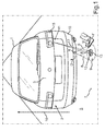
- Fig. 1 shows a motor vehicle 1, which may be, for example, a motor vehicle, especially a passenger car, act. Shown is a rear 2 of the motor vehicle 1.
- the rear 2 may have a flap 3, in particular a tailgate or a trunk lid.
- the following explanations may, however, additionally or alternatively to the flap 3 at the rear 2, also be applied to another flap of the motor vehicle 1, for example a vehicle door or the hood.
- a user can open the flap 3 without contact, by executing, for example, with a foot F a pivoting movement M at the rear 2.
- the pivoting movement M is detected and upon detection of the pivoting movement, the flap 3, for example, opened by a motor.
- This detection of the presence of the foot F may be provided by a sensor device 4 which may be adapted to detect the foot F of the user and / or the pivotal movement M of the foot F outside the motor vehicle 1 in an environment 5.
- the sensor device 4 can for this purpose have a detection area 6 for detecting a presence of the foot F.
- the detection region 6 can be directed, starting from the sensor device 4, onto a bottom surface 7, for example a road. In this way, a gap 8 between the sensor device 4 and a part 9 of the bottom surface 7 detected by the detection region 6 is delimited by the detection region 6, which is suitable for the user holding his foot F in, and thus in the sensor device 4 a triggering or sensor signal D generated.
- This sensor signal D can be used to control, for example, the motorized tailgate 3 in a conventional manner.
- a mark can be provided for the user.
- a lighting device 11 can be provided in the motor vehicle 1.
- the luminous marking 12 can have a luminous core region 13 whose brightness is so large in relation to a luminous edge region 14 surrounding the luminous core region 13 that a predetermined minimum contrast of the luminous core region 13 results in relation to the luminous edge region 14.
- the user can reliably recognize or perceive the luminous core region 13 visually.
- this mark is particularly reliable, even if the motor vehicle 1 is dirty or dirty because it has been driven, for example, by snow or mud.
- the sensor device 4 may have a housing 18, which may be formed, for example, of plastic and / or a material that shields a housing interior 19 against electromagnetic interference radiation.
- a sensor element 20 In the housing 18, that is, in the housing interior 19, a sensor element 20 or it may be more Be arranged sensor elements. In the example shown, only one sensor element 20 is provided for providing the detection area 6.
- the sensor housing 18 is arranged on a first component 10 of the motor vehicle 1.
- the first component 10 may be, for example, a bumper, for example the bumper at the rear 2. This has the advantage that the sensor device 4 has a distance to the bottom surface 7, which is smaller than one meter, in particular smaller than 17 cm, is. In other words, it is ensured that the foot F is reliably detected by the sensor element 20. Too large a distance between the sensor element 20 and the foot F could make the detection unreliable.
- the lighting device 11 may be arranged in another, second component 15, which is different from the component 10.
- the component 15 is arranged higher than the component 10 along a vehicle vertical axis 16 or z-direction. This results in the higher probability that the component 15 has a lower degree of contamination than the component 10.
- the likelihood that light leakage of a light beam 17 emitted or emitted to generate the luminous marking 12 is obstructed or blocked by dirt is reduced.
- the component 15 is preferably a vehicle lamp of the motor vehicle 1, in particular a tail lamp.
- the component 15 may for example have a brake light and / or a reversing light.
- the sensor element 20 may, for example, be an infrared-based motion sensor, an ultrasound sensor, a camera or an optical receiver for ambient brightness.
- sensor signal D can be generated by sensor device 4.
- the sensor device 4 may be coupled to a control device 22, which may be, for example, a control device of the motor vehicle 1.
- the control device 22 may be part of the sensor device 4. Of the sensor device 4, only the housing 18 with the sensor element 20 has to be arranged on the component 10.
- the control device 22 may receive the sensor signal D and, in response to the sensor signal D, actuate a locking system 23, which may be designed, for example, for a motorized tailgate move. In the case of the locking system 23, a control circuit can be provided for this purpose, for example.
- a radio key receiver 24 may also be provided which detects a presence of a radio key in the environment 5, for example in an area closer than 20 meters, in particular closer than 10 meters, to the motor vehicle 1.
- the radio key receiver 24 can likewise be coupled to the control device 22 and emit a presence or presence signal P to the control device 22 when a radio key is detected in the environment 5.
- the control device 22 generates a control signal for the locking system 23 as a function of the sensor signal D only in the presence of a presence signal P.
- the sensor element 20 and the lighting device are activated only in the presence signal P present, so that the light-emitting marker 13 is generated only at present presence signal P on the bottom surface 7 and the sensor device 4 detects an object in the detection area 6.
- the lighting device 11 can be activated by the control device 22, for example.
- the lighting device 11 may be integrated in the component 15, that in particular a vehicle lamp, preferably a tail lamp, is.
- a light source 25 may be provided, which may comprise, for example, a light emitting diode and / or a laser.
- the light source 25 may be designed to generate a functional light of the taillight, for example a tail light, a brake light, a reversing light and / or a fog light. It may also be a light source 25, which may be provided exclusively for generating the luminous marking 13.
- an optical element 26 can be provided as part of the lighting device 11.
- the optical element 26 may be configured to form light 27 radiated from the light source 25 to the light beam 17, which falls on the part 9 of the bottom surface 7 and thereby generates the luminous marking 12.
- the lighting device 11 is integrated in the component 15 and does not have to be arranged in the housing 18, resulting in a particularly small-sized sensor housing for the sensor element 20. Furthermore, this is also the interconnection in the housing 18th and the cooling surface requirement is reduced in an advantageous manner. There is no need to provide circuitry for the light source 25 and optical element 26, nor cooling for these components in the housing 18.
- the lighting unit that is, the lighting device 11 for generating the visible activation point on the bottom surface 7
- a dedicated light source that is, for example, a light emitting diode and driver chips
- the size of the sensor housing 18 can be reduced.
- a cooling surface and further thermal adjustments must be provided in the sensor housing 18, so that both the sensor element 20 and the light source 25 can be provided in one and the same housing.
- the optical element 26 can be used, for example, by an optical waveguide and / or shutter (controllable diaphragm) and / or one or more prisms or for example a mirror as an optical deflection to image the visible activation point, that is to say the luminous marking 12, on the bottom surface 7 .
- the light 27 can also be bundled by a plurality of light sources in the taillight via the optical element 26 so as to set the brightness, that is to say the luminous intensity, lighter or darker, for example as a function of ambient light 5.
- Suitable control signals for controlling the optical element 26, for example motorized pivoting of a mirror can be generated by the control device 22, for example.
- the motor vehicle 1 thus provides a sensor device for a non-contact flap opener, the light exit region 28 of which does not easily contaminate the light beam 17 for generating the illuminated marking 12 and which has a sensor housing for at least one receiver, for example an optical receiver, a camera or an ultrasonic receiver, the compact builds.
- a particularly low-cost and therefore inexpensive sensor device can be provided.
- the lighting device 11 is arranged in another assembly of the motor vehicle 1, namely the component 5, as the sensor housing 18.
- the receiver of the sensor device needs to be housed in the sensor housing, that is, the sensor element 20 or a Arrangement of several sensor elements.
- the lighting device 11 is arranged higher than the sensor housing 18th
- the lighting device 11 is arranged in the region of the tail light of a motor vehicle. It is further preferred that the lighting device 11 is integrated in the tail light. In this case, in particular in the tail light components already existing, such as light sources and / or optics for providing a beam path, for the function of marking the monitored area 8 and 9 are used. Overall, the example shows how the invention allows illumination for tailgate openers out of taillights out.
Abstract
Die Erfindung betrifft eine Vorrichtung für ein Kraftfahrzeug (1). Eine Sensoreinrichtung (4) weist ein Gehäuse (18) auf, das an einem ersten Bauteil (10) des Kraftfahrzeugs (1) in einer ersten Einbaulage befestigbar ausgestaltet ist und in dem zumindest ein Sensorelement (20) angeordnet ist, das in der ersten Einbaulage des Gehäuses (18) einen sich zu einer Bodenfläche (7) einer Umgebung (5) des Kraftfahrzeugs (1) hin erstreckenden Erfassungsbereich (6) aufweist und dazu ausgelegt ist, ein von einer Anwesenheit eines Objekts (F), insbesondere eines Körperteils (F) eines Benutzers, in dem Erfassungsbereich (6) abhängiges Sensorsignal zu erzeugen. Eine Leuchteinrichtung (11) ist dazu ausgelegt, durch Abstrahlen von Licht (17) in einem von dem Erfassungsbereich (6) erfassten Teil (9) der Bodenfläche (7) eine Leuchtmarkierung (12) zu erzeugen. Die Leuchteinrichtung (11) ist außerhalb des Gehäuses (18) der Sensoreinrichtung (4) in oder an einem von dem ersten Bauteil (10) verschiedenen zweiten Bauteil (15) des Kraftfahrzeugs (1) anordenbar ausgestaltet.The invention relates to a device for a motor vehicle (1). A sensor device (4) has a housing (18) which can be fastened to a first component (10) of the motor vehicle (1) in a first installation position and in which at least one sensor element (20) is arranged, which in the first installation position of the housing (18) has a detection area (6) extending to a bottom surface (7) of an environment (5) of the motor vehicle (1) and is designed to detect a presence of an object (F), in particular a body part (F ) of a user to generate in the detection area (6) dependent sensor signal. A lighting device (11) is designed to generate a luminous marking (12) by emitting light (17) in a part (9) of the bottom surface (7) detected by the detection region (6). The light-emitting device (11) is arranged outside the housing (18) of the sensor device (4) in or on a second component (15) of the motor vehicle (1) that is different from the first component (10).
Description
Die Erfindung betrifft eine Vorrichtung für ein Kraftfahrzeug mit einer Sensoreinrichtung zum Detektieren eines Objekts, insbesondere eines Körperteils, in einem Erfassungsbereich außerhalb des Kraftfahrzeugs und mit einer Leuchteinrichtung zum Markieren des Erfassungsbereichs. Zu der Erfindung gehören auch eine Fahrzeugleuchte und ein Kraftfahrzeug.The invention relates to a device for a motor vehicle with a sensor device for detecting an object, in particular a body part, in a detection area outside the motor vehicle and with a lighting device for marking the detection area. The invention also includes a vehicle lamp and a motor vehicle.
Eine Vorrichtung der genannten Art ist beispielsweise aus der
Aus der
Bei den aus dem Stand der Technik bekannten optischen Heckklappenöffnern wurde als Nachteil erkannt, dass bei einer Verschmutzung der Leuchteinrichtung, welche die Leuchtmarkierung auf die Bodenfläche projizieren soll, diese Leuchtmarkierung nicht mehr vom Benutzer erkennbar ist. Dann weiß der Benutzer nicht, wo er mit seinem Fuß eine Schwenkbewegung ausführen muss, um das Öffnen der Heckklappe auszulösen.In the known from the prior art optical tailgate openers has been recognized as a disadvantage that when pollution of the lighting device, which is to project the luminous marking on the floor surface, this luminous marking is no longer recognizable by the user. Then the user does not know where to pivot with his foot in order to trigger the opening of the tailgate.
Der Erfindung liegt die Aufgabe zugrunde, bei einem Kraftfahrzeug mit fahrzeugexternem Erfassungsbereich zum Detektieren einer Anwesenheit eines Objekts, insbesondere eines Körperteils, den Erfassungsbereich für die Benutzer zuverlässig zu markieren.The invention is based on the object, in a motor vehicle with vehicle-external detection area for detecting a presence of an object, in particular a body part, to mark the detection area for the user reliably.
Die Aufgabe wird durch die Gegenstände der unabhängigen Patentansprüche gelöst. Vorteilhafte Weiterbildungen der Erfindung sind durch die Merkmale der abhängigen Patentansprüche gegeben.The object is solved by the subject matters of the independent claims. Advantageous developments of the invention are given by the features of the dependent claims.
Erfindungsgemäß ist eine Vorrichtung für ein Kraftfahrzeug bereitgestellt, welche eine Sensoreinrichtung und eine Leuchteinrichtung aufweist. Die Sensoreinrichtung weist ein Sensorgehäuse oder kurz Gehäuse auf, das in einer vorbestimmten ersten Einbaulage an einem ersten Bauteil des Kraftfahrzeugs befestigbar oder anordenbar ausgestaltet ist. Hierzu kann das Gehäuse z.B. einen Flansch zum Anschrauben oder eine Klebefläche zum Ankleben an das erste Bauteil aufweisen. In dem Gehäuse ist zumindest ein Sensorelement angeordnet, das in der bestimmungsgemäßen ersten Einbaulage des Gehäuses einen sich zu einer Bodenfläche einer Umgebung des Kraftfahrzeugs, insbesondere zu einer Straße, hin erstreckenden Erfassungsbereich aufweist und dazu ausgelegt ist, ein von einer Anwesenheit eines Objekts, insbesondere eines Körperteils eines Benutzers, in dem Erfassungsbereich abhängiges Sensorsignal zu erzeugen. Mit anderen Worten weist der Erfassungsbereich des zumindest einen Sensorelements nach unten, wenn das Gehäuse bestimmungsgemäß in der ersten Einbaulage in dem Kraftfahrzeug angeordnet ist. Es kann hierbei vorgesehen sein, dass die Gegenwart des Objekts und/oder eine Bewegung des Objekts signalisiert wird.According to the invention, a device for a motor vehicle is provided which has a sensor device and a lighting device. The sensor device has a sensor housing or housing for short, which can be fastened or arranged in a predetermined first installation position on a first component of the motor vehicle. For this, the housing may be e.g. a flange for screwing or an adhesive surface for adhering to the first component. In the housing, at least one sensor element is arranged, which in the intended first installation position of the housing has a to a bottom surface of an environment of the motor vehicle, in particular to a road, extending detection area and is designed to one of a presence of an object, in particular a Body part of a user to generate in the detection area dependent sensor signal. In other words, the detection range of the at least one sensor element downwards, when the housing is arranged as intended in the first installation position in the motor vehicle. It can be provided here that the presence of the object and / or a movement of the object is signaled.
Die Leuchteinrichtung ist dazu ausgelegt, durch Abstrahlen von Licht in einem von dem Erfassungsbereich erfassten Bereich der Bodenfläche, einen Lichtfleck oder eine Leuchtmarkierung zu erzeugen. Insbesondere ist die Leuchtmarkierung kleiner als der Bereich auf der Bodenfläche, der von dem Erfassungsbereich des zumindest einen Sensorelements erfasst oder abgedeckt ist. Mit anderen Worten durchdringt dann zumindest ein Lichtstrahl des Lichts den Erfassungsbereich. Die Leuchteinrichtung kann in den Erfassungsbereich hineinleuchten.The lighting device is designed to generate a light spot or a luminous marking by emitting light in a region of the floor area covered by the detection area. In particular, the luminous marking is smaller than the area on the bottom surface, which is detected or covered by the detection area of the at least one sensor element. In other words, at least one light beam of the light then penetrates the detection area. The lighting device can illuminate into the detection area.
Erfindungsgemäß ist die Leuchteinrichtung außerhalb des Gehäuses der Sensoreinrichtung angeordnet. Mit anderen Worten sind das Gehäuse und die Leuchteinrichtung vor dem Einbau in das Kraftfahrzeug als zwei Einzelbauteile bereitgestellt, die unabhängig voneinander in dem Kraftfahrzeug positioniert oder angeordnet werden können. Insbesondere ist die Leuchteinrichtung in einem von dem ersten Bauteil, an welchem das Gehäuse angeordnet ist, verschiedenen zweiten Bauteil des Kraftfahrzeugs anordenbar ausgestaltet. Alternativ dazu kann die Leuchteinrichtung in einem Bereich des zweiten Bauteils, also an dem zweiten Bauteil angeordnet sein.According to the invention, the lighting device is arranged outside the housing of the sensor device. In other words, the housing and the lighting device are provided prior to installation in the motor vehicle as two individual components that can be positioned or arranged independently of one another in the motor vehicle. In particular, the lighting device is designed to be arrangeable in one of the first component, on which the housing is arranged, different second component of the motor vehicle. Alternatively, the lighting device may be arranged in a region of the second component, ie on the second component.
In einem zweiten Aspekt sieht die Erfindung ein Kraftfahrzeug vor, in welchem eine Ausführungsform der erfindungsgemäßen Vorrichtung bereitgestellt ist.In a second aspect, the invention provides a motor vehicle in which an embodiment of the device according to the invention is provided.
Bei der erfindungsgemäßen Vorrichtung und dem erfindungsgemäßen Kraftfahrzeug ergibt sich der Vorteil, dass die Leuchteinrichtung unabhängig von der Sensoreinrichtung in oder an einem zweiten Bauteil des Kraftfahrzeugs angeordnet werden kann. Hierdurch ist es in vorteilhafter Weise möglich, die Sensoreinrichtung an einem ersten Bauteil anzubringen, von wo aus die Sensierung der Anwesenheit des Objekts besonders zuverlässig durchgeführt werden kann, beispielsweise nahe an der Bodenfläche. Insbesondere ist hierzu die Sensoreinrichtung bei dem erfindungsgemäßen Kraftfahrzeug in einem Abstand von höchstens 80 cm, insbesondere höchstens 60 cm, von der Bodenfläche entfernt angeordnet. Unabhängig davon kann die Leuchteinrichtung an oder in dem zweiten Bauteil angeordnet sein, dass derart gewählt werden kann, dass es sich um ein Bauteil handelt, das mit einer geringeren Wahrscheinlichkeit verschmutzt bzw. verdeckt wird, als das erste Bauteil. Hierdurch ist gewährleistet, dass der Lichtaustritt aus der Leuchteinrichtung hin zu der Bodenfläche nicht von an dem zweiten Bauteil haftendem Schmutz beeinträchtigt wird.In the device according to the invention and the motor vehicle according to the invention there is the advantage that the lighting device can be arranged independently of the sensor device in or on a second component of the motor vehicle. This makes it possible in an advantageous manner to attach the sensor device to a first component, from where the sensing of the presence of the object can be carried out particularly reliably, for example, close to the bottom surface. In particular, for this purpose, the sensor device in the motor vehicle according to the invention at a distance of at most 80 cm, in particular at most 60 cm, arranged away from the bottom surface. Regardless of this, the lighting device can be arranged on or in the second component, which can be selected such that it is a component which is less likely to be contaminated or concealed than the first component. This ensures that the light emission from the lighting device to the bottom surface is not affected by adhering to the second component dirt.
In einer Ausführungsform der Erfindung ist die Leuchteinrichtung in einer zweiten Einbaulage in dem Kraftfahrzeug anordenbar ausgestaltet, wobei die zweite Einbaulage entlang einer Fahrzeughochachse des Kraftfahrzeugs höher angeordnet als die die erste bestimmungsgemäße Einbaulage des Gehäuses. Mit anderen Worten ist die Leuchteinrichtung bevorzugt oberhalb der Sensoreinrichtung in dem erfindungsgemäßen Kraftfahrzeug angeordnet, wobei oberhalb auch schräg oberhalb umfasst. Insbesondere ist also das erste Bauteil näher an der Bodenfläche angeordnet als das zweite Bauteil. Bevorzugt beträgt eine Einbauhöhe der Leuchteinrichtung mindestens 60 cm, insbesondere mindestens 80 cm. Hierdurch ergibt sich der Vorteil, dass die Leuchteinrichtung mit einer geringeren Wahrscheinlichkeit von beispielsweise bei einer Fahrt aufgeworfenem Material, beispielsweise Schmutz, Staub, Schnee und/oder Matsch, verdeckt wird.In one embodiment of the invention, the lighting device is designed to be arrangeable in a second installation position in the motor vehicle, wherein the second mounting position along a vehicle vertical axis of the motor vehicle arranged higher than the first intended installation position of the housing. In other words, the lighting device is preferably arranged above the sensor device in the motor vehicle according to the invention, wherein above also includes obliquely above. In particular, therefore, the first component is arranged closer to the bottom surface than the second component. An installation height of the lighting device is preferably at least 60 cm, in particular at least 80 cm. This results in the advantage that the lighting device is covered with a lower probability of, for example, when driving thrown up material, such as dirt, dust, snow and / or mud.
In einer Ausführungsform ist das Gehäuse an einem Stoßfänger oder einem Trittbrett oder einer Heckklappe befestigbar ausgestaltet. Durch Anordnen der Sensoreinrichtung an dem Stoßfänger oder Trittbrett ergibt sich der Vorteil, dass sich die Sensoreinrichtung in einem Abstand von höchstens 80 cm, insbesondere höchstens 60 cm von der Bodenfläche entfernt befindet. Hierdurch ist die Detektion des Objekts besonders zuverlässig. Das Anordnen an der Heckklappe weist den Vorteil auf, dass beispielsweise eine Rückfahrkamera als Sensorelement genutzt werden kann. Das Vorsehen der Sensoreinrichtung im Trittbrett weist den Vorteil auf, dass eine Bewegungserkennung im Bereich einer Fahrertür oder einer anderen Fahrzeugtür ermöglicht ist.In one embodiment, the housing is configured fastened to a bumper or a footboard or a tailgate. By arranging the sensor device on the bumper or running board, there is the advantage that the sensor device is located at a distance of at most 80 cm, in particular at most 60 cm from the bottom surface. As a result, the detection of the object is particularly reliable. The arrangement on the tailgate has the advantage that, for example, a reversing camera can be used as a sensor element. The provision of the sensor device in the running board has the advantage that motion detection in the area of a driver's door or another vehicle door is made possible.
In einer Ausführungsform der Erfindung weist das zumindest eine Sensorelement der Sensoreinrichtung jeweils einen optischen Empfänger, insbesondere einen lichtempfindlichen Sensor, oder eine Kamera oder einen Ultraschallsensor auf. Ein optischer Empfänger ist mit besonders geringem technischem Aufwand bereitstellbar. Eine Kamera kann vorteilsbringend einer doppelten Funktion zugeführt werden. Beispielsweise kann eine Rückfahrkamera genutzt, die während einer Rückwärtsfahrt des Kraftfahrzeugs zum Einsehen des Heckbereichs vom Fahrer genutzt werden kann. Die Kamera kann insbesondere in der beschriebenen Weise in einer Heckklappe des Kraftfahrzeugs angeordnet sein. Ein Ultraschallsensor weist den Vorteil auf, dass eine Detektion eines Objekts im Erfassungsbereich auch beim verschmutzten ersten Bauteil durch eine Schmutzschicht hindurch möglich ist.In one embodiment of the invention, the at least one sensor element of the sensor device in each case has an optical receiver, in particular a photosensitive sensor, or a camera or an ultrasonic sensor. An optical receiver can be provided with particularly low technical effort. A camera can advantageously be fed to a dual function. For example, a reversing camera can be used, which can be used by the driver during rearward travel of the motor vehicle to view the rear area. The camera can be arranged in particular in the manner described in a tailgate of the motor vehicle. An ultrasonic sensor has the advantage that a detection of an object in the detection area is possible even when the soiled first component through a dirt layer.
In einer Ausführungsform der Erfindung ist die Leuchteinrichtung mit einem Helligkeitssensor gekoppelt, der ein mit einer Umgebungshelligkeit korrelierendes Helligkeitssignal zu erzeugen ausgelegt ist. Ein solcher Helligkeitssensor kann in einem Kraftfahrzeug beispielsweise auch zum Umschalten zwischen Tagfahrlicht und Abblendlicht bereitgestellt sein. Der Helligkeitssensor kann auch beispielsweise mittels einer Kamera des Kraftfahrzeugs realisiert sein. Die Leuchteinrichtung ist bei dieser Ausführungsform dazu ausgelegt, in Abhängigkeit von dem Helligkeitssignal des Helligkeitssensors, eine Strahlungsintensität des zum Erzeugen der Leuchtmarkierung abgestrahlten Lichts einzustellen. Hierdurch ergibt sich der Vorteil, dass abhängig vom Umgebungslicht eine vom Benutzer durch einen vorbestimmten Mindestkontrast erkennbare Leuchtmarkierung auf der Bodenfläche erzeugt werden kann.In one embodiment of the invention, the lighting device is coupled to a brightness sensor which is designed to generate a brightness signal correlating with an ambient brightness. Such a brightness sensor can be provided in a motor vehicle, for example, for switching between daytime running lights and low beam. The brightness sensor can also be realized for example by means of a camera of the motor vehicle. In this embodiment, the lighting device is designed to set a radiation intensity of the light emitted for generating the luminous marking as a function of the brightness signal of the brightness sensor. This results in the advantage that, depending on the ambient light, a luminous marking recognizable by the user through a predetermined minimum contrast can be generated on the floor surface.
In einer Ausführungsform der Erfindung ist die Sensoreinrichtung mit einer Schließanlage des Kraftfahrzeugs koppelbar ausgestaltet und eine Steuereinrichtung der Sensoreinrichtung ist dazu ausgelegt, in Abhängigkeit von dem Sensorsignal des zumindest einen Sensorelements durch Aussenden eines Steuersignals an die Schließanlage eine Klappe des Kraftfahrzeugs, insbesondere eine Heckklappe zu entriegeln und/oder zu öffnen. Zum Öffnen der Heckklappe kann ein entsprechender Aktor bzw. Motor vorgesehen sein. Hierdurch kann in vorteilsbringender Weise der bereits beschriebene optische Heckklappenöffner bereitgestellt werden. Es kann aber auch beispielsweise eine Fahrertür aufgeschwenkt werden, damit ein beispielsweise mit Einkaufstüten beladener Fahrer die Tür nicht manuell öffnen muss. Zum Ankoppeln der Sensoreinrichtung an die Schließanlage kann z.B. eine elektrische Schnittstelle, insbesondere ein Stecker oder eine Buchse oder ein Busankoppler, bereitgestellt sein.In one embodiment of the invention, the sensor device is designed to be coupled to a locking system of the motor vehicle and a control device of the sensor device is adapted to unlock depending on the sensor signal of the at least one sensor element by emitting a control signal to the locking system a flap of the motor vehicle, in particular a tailgate and / or open. To open the tailgate, a corresponding actuator or motor can be provided. As a result, the already described optical tailgate opener can be provided in an advantageous manner. However, it is also possible, for example, to swivel open a driver's door, so that a driver, for example, loaded with shopping bags, does not have to open the door manually. For coupling the sensor device to the locking system, it is possible, for example, to provide an electrical interface, in particular a plug or a socket or a bus coupling unit.
In einer Ausführungsform ist die Leuchteinrichtung dazu ausgelegt, die Leuchtmarkierung nur bei still stehendem und/oder abgeschaltetem und/oder verriegeltem Kraftfahrzeug und/oder aktivierter Sensoreinrichtung zu erzeugen. Hierdurch ergibt sich der Vorteil, dass die Leuchtmarkierung im Betrieb des Kraftfahrzeugs niemanden unnötig verwirrt oder irritiert.In one embodiment, the lighting device is designed to generate the illuminated marking only when the motor vehicle is at a standstill and / or switched off and / or locked and / or activated sensor device. This results in the advantage that the luminous marking unnecessarily confuses or irritates anyone in the operation of the motor vehicle.
In einer Ausführungsform sind die Leuchteinrichtung und die Sensoreinrichtung mit einem Funkschlüsselempfänger des Kraftfahrzeugs koppelbar ausgestaltet. Die Vorrichtung ist hierbei dazu ausgelegt, in Abhängigkeit von einem Funksignal eines Funkschlüssels die Sensoreinrichtung und die Leuchteinrichtung von einem Aus-Zustand in einen Aktivzustand zu schalten, in welchem die Sensoreinrichtung das Detektieren durchführt und die Leuchteinrichtung die Leuchtmarkierung erzeugt. Hierdurch ergibt sich der Vorteil, dass nur eine zum Zutritt befugte Person, welche den Funkschlüssel bei sich trägt, mittels der Sensoreinrichtung das Kraftfahrzeug steuern kann. Die Kopplung mit dem Funkschlüsselempfänger kann technisch in derselben Weise ausgeführt sein, wie es bereits im Zusammenhang mit der Kopplung an die Schließanlage beschrieben worden ist.In one embodiment, the lighting device and the sensor device can be coupled to a radio key receiver of the motor vehicle. In this case, the device is designed to switch the sensor device and the lighting device from an off state to an active state in response to a radio signal of a radio key, in which the sensor device performs the detection and the lighting device generates the light marking. This results in the advantage that only a person authorized to enter, who carries the radio key with him, can control the motor vehicle by means of the sensor device. The coupling with the radio key receiver can be carried out technically in the same way as has already been described in connection with the coupling to the locking system.
In einer Ausführungsform ist die Leuchteinrichtung in oder an einer Fahrzeugleuchte, insbesondere einer Heckleuchte, anordenbar ausgestaltet. Bevorzugt ist die Leuchteinrichtung in eine Fahrzeugleuchte integriert, d.h. die Fahrzeugleuchte ist Bestandteil dieser Ausführungsform der erfindungsgemäßen Vorrichtung. Hierdurch ergibt sich der Vorteil, dass die Leuchteinrichtung in einem Bauteil angeordnet ist, das bei bestimmungsgemäßen Betrieb des Kraftfahrzeugs im Wesentlichen frei von Verschmutzung ist. Die Fahrzeugleuchte kann auch ein Seitenblinker sein. Hierdurch ergibt sich der Vorteil, dass eine Bewegungserkennung für eine Fahrertür oder eine andere Fahrzeugtür ermöglicht ist.In one embodiment, the lighting device in or on a vehicle lamp, in particular a tail light, arranged configured. Preferably, the lighting device is integrated in a vehicle lamp, i. the vehicle lamp is part of this embodiment of the device according to the invention. This results in the advantage that the lighting device is arranged in a component which is substantially free from contamination during normal operation of the motor vehicle. The vehicle light can also be a side indicator. This results in the advantage that a motion detection for a driver's door or another vehicle door is possible.
Im Zusammenhang mit der Integration der Leuchteinrichtung in eine Fahrzeugleuchte ergeben sich mehrere vorteilhafte Weiterbildungen, die im Folgenden beschrieben sind.In connection with the integration of the lighting device in a vehicle lamp, several advantageous developments, which are described below.
In einer Weiterbildung ist die Leuchteinrichtung dazu ausgelegt, zum Erzeugen des Lichts zumindest eine Leuchtdiode und/oder zumindest einen Laser der Fahrzeugleuchte zu aktivieren. Bei der Leuchtdiode und/oder dem Laser handelt es sich dabei jeweils um eine Lichtquelle zum Erzeugen eines Abblendlichts, eines Fernlichts, eines Bremslichts, eines Rückfahrlichts, eines Hecklichts, eines Fahrtrichtungsanzeigelichts, das heißt eines Blinklichts, eines Nebelleuchtenlichts und/oder eines Tagfahrlichts. Mit anderen Worten wird bei dieser Weiterbildung zum Erzeugen der Leuchtmarkierung eine Lichtquelle genutzt, die insbesondere im Fahrbetrieb des Kraftfahrzeugs zum Erzeugen eines Lichtscheins für eine weitere Beleuchtungsfunktionalität der Fahrzeugleuchte bereitgestellt ist. Hierdurch ergibt sich der Vorteil, dass beim Erzeugen der Leuchtmarkierung eine eigens nur dafür bereitgestellte dedizierte Lichtquelle bereitgestellt sein muss.In a development, the lighting device is designed to activate at least one light-emitting diode and / or at least one laser of the vehicle light for generating the light. The light emitting diode and / or the laser are each a light source for generating a low beam, a high beam, a brake light, a reversing light, a tail light, a direction indicator light, that is one Flashing light, a fog light and / or a daytime running light. In other words, a light source is used in this development for generating the luminous marking, which is provided in particular during driving operation of the motor vehicle for generating a light for a further illumination functionality of the vehicle lamp. This has the advantage that, when generating the luminous marking, a dedicated light source has to be provided for this purpose.
In einer Weiterbildung weist die Leuchteinrichtung ein optisches Element zum optischen Bündeln und/oder zum optischen Umlenken des zum Erzeugen der Leuchtmarkierung vorgesehenen Lichts vor dessen Austritt in die Umgebung auf. Hierdurch ergibt sich der Vorteil, dass man beim Bereitstellen der Leuchteinrichtung nicht darauf angewiesen ist, die Lichtquelle der Leuchteinrichtung zur Bodenfläche hin weist. Dadurch kann die Lichtquelle der Leuchteinrichtung mit besonders geringem technischem Aufwand in eine Fahrzeugleuchte integriert sein.In one development, the lighting device has an optical element for optically bundling and / or for optically deflecting the light provided for generating the luminous marking before it exits into the environment. This has the advantage that it is not dependent upon the provision of the lighting device, the light source of the lighting device facing the bottom surface. Thereby, the light source of the lighting device can be integrated with a particularly low technical effort in a vehicle lamp.
Das optische Element ist insbesondere zum Abzweigen des Lichts aus einem Strahlengang der Fahrzeugleuchte ausgelegt. Hierdurch ergibt sich der Vorteil, dass mittels des Leuchtelements das Licht aus nicht mit einer dedizierten, nur für das Erzeugen der Leuchtmarkierung vorgesehenen Lichtquelle, sondern mit einer anderen Lichtquelle der Fahrzeugleuchte erzeugt werden kann und dieses Licht bedarfsweise mittels des optischen Elements aus dem Strahlengang der Fahrzeugleuchte abgezweigt werden kann. Der Strahlengang ist derjenige Raumbereich in der Fahrzeugleuchte, welcher das Licht insbesondere im Fahrbetrieb des Kraftfahrzeugs, zu einem Lichtschein für ein Funktionslicht zusammenfasst, also eines der bereits beschriebenen Leuchtfunktionen, von denen hier nur beispielhaft das Hecklicht und das Bremslicht und die Beleuchtung für den Rückwärtsgang noch einmal wiederholend angegeben sind.The optical element is designed in particular for branching off the light from a beam path of the vehicle lamp. This results in the advantage that the light can be generated by means of the luminous element not with a dedicated, provided only for generating the luminous marking light source, but with another light source of the vehicle lamp and this light, if necessary, by means of the optical element from the beam path of the vehicle lamp can be diverted. The beam path is that area in the vehicle lamp, which summarizes the light in particular when driving the motor vehicle to a light for a functional light, so one of the already described lighting functions, of which here only by way of example, the taillight and the brake light and the lighting for reverse still once repeated.
In einer Ausführungsform ist das optische Element zwischen einem Umlenkzustand, in welchem das optische Element das Lichts zum Erzeugen der Leuchtmarkierung von einer Lichtquelle der Fahrzeugleuchte empfängt und in dem Bereich zum Erzeugen der Leuchtmarkierung umlenkt, und einen Neutralzustand, in welchem das optische Element das Licht der Lichtquelle passieren lässt, umschaltbar ausgestaltet. Das optische Element kann hierzu beispielsweise einen verschwenkbaren Spiegel oder ein bewegbar gelagertes Prisma aufweisen. Hierdurch ergibt sich der Vorteil, dass wieder eine Lichtquelle der Fahrzeugleuchte genutzt werden kann, die nicht ausschließlich zum Erzeugen der Leuchtmarkierung bereitgestellt ist, und im Neutralzustand, insbesondere während eines Fahrbetriebs des Kraftfahrzeugs, der Strahlengang zum Erzeugen eines beschriebenen Funktionslicht nicht beeinträchtigt ist.In one embodiment, the optical element is between a deflection state in which the optical element receives the light for generating the luminous marking from a light source of the vehicle lamp and deflects in the area for generating the luminous marking, and a neutral state in which the optical element, the light of Light source can happen, designed switchable. For this purpose, the optical element can have, for example, a pivotable mirror or a movably mounted prism. This results in the advantage that again a light source of the vehicle lamp can be used, which is not provided exclusively for generating the luminous marking, and in the neutral state, in particular during a Driving operation of the motor vehicle, the beam path for generating a described functional light is not impaired.
Um die beschriebenen Weiterbildungen zu realisieren, weist das optische Element insbesondere einen Lichtleiter und/oder eine Blende und/oder ein Prisma und/oder einen bewegbar gelagerten Spiegel auf. Ein Lichtleiter ist beispielsweise mittels eines Spritzgussverfahrens in eine Streuscheibe der Fahrzeugleuchte integriert. Mittels einer Blende, insbesondere einer verstellbaren Blende, kann ein Durchmesser der Leuchtmarkierung gezielt eingestellt werden. Ein Prisma ermöglicht das Umlenken von Licht aus einem Strahlengang der Fahrzeugleuchte. Der bewegbare Spiegel kann in der bereits beschriebenen Weise vorteilsbringend eingesetzt werden.In order to realize the further developments described, the optical element in particular has a light guide and / or a diaphragm and / or a prism and / or a movably mounted mirror. A light guide is integrated, for example by means of an injection molding process in a lens of the vehicle lamp. By means of a diaphragm, in particular an adjustable diaphragm, a diameter of the luminous marking can be adjusted specifically. A prism allows the deflection of light from a beam path of the vehicle lamp. The movable mirror can be advantageously used in the manner already described.
Wie vorstehend ausgeführt, kann die Leuchteinrichtung in eine Fahrzeugleuchte des Kraftfahrzeugs integriert sein. Entsprechend ergibt sich als ein weiterer Aspekt der Erfindung eine Fahrzeugleuchte, insbesondere eine Heckleuchte, für ein Kraftfahrzeug. Die erfindungsgemäße Fahrzeugleuchte weist eine Leuchteinrichtung, die dazu ausgelegt ist, bei einer vorbestimmten Einbaulage der Fahrzeugleuchte in dem Kraftfahrzeug, also einer bestimmungsgemäßen Einbaulage, auf einer sich horizontal erstreckenden Bodenfläche einer Umgebung der Fahrzeugleuchte also dem Fahruntergrund, das heißt der Straße, durch Abstrahlen von Licht eine Leuchtmarkierung zu erzeugen, die einen Leuchtkernbereich und einen den Leuchtkernbereich umgebenen, insbesondere umschließenden Leuchtrandbereich aufweist und bei der ein Durchmesser des Leuchtkernbereichs kleiner als ein Meter, insbesondere kleiner als 50 cm, bevorzugt kleiner als 25 cm, ist und bei der eine Helligkeit der Leuchtmarkierung in dem Leuchtkernbereich zumindest dreimal, insbesondere mindestens fünfmal, bevorzugt mindestens zehnmal, größer ist als in dem Leuchtrandbereich. Die Angabe beziehen sich insbesondere auf eine Einbaulage der Leuchteinrichtung, die in einem Entfernungsbereich von 60 cm bis 150 cm über der Bodenfläche liegt. Die Helligkeit kann beispielsweise mittels eines Helligkeitssensors und/oder als Leuchtintensität auf der Bodenfläche gemessen sein. Die erfindungsgemäße Fahrzeugleuchte kann in Kombination mit einer Sensoreinrichtung vorteilsbringend dazu genutzt werden, ein erfindungsgemäßes Kraftfahrzeug bereit zu stellen.As stated above, the lighting device can be integrated in a vehicle lamp of the motor vehicle. Accordingly, as a further aspect of the invention results in a vehicle lamp, in particular a tail lamp, for a motor vehicle. The vehicle lamp according to the invention has a lighting device which is designed, in a predetermined mounting position of the vehicle lamp in the motor vehicle, ie a proper installation position on a horizontally extending bottom surface of an environment of the vehicle lamp so the driving surface, that is the road, by emitting light to produce a luminous marking which has a luminous core region and a luminous edge region surrounding the luminous core region and in which a diameter of the luminous core region is less than one meter, in particular less than 50 cm, preferably less than 25 cm, and a brightness of the luminous marking in the luminous core region at least three times, in particular at least five times, preferably at least ten times, is greater than in the luminous edge region. The information relates in particular to an installation position of the lighting device, which lies in a distance range of 60 cm to 150 cm above the ground surface. The brightness can be measured for example by means of a brightness sensor and / or as a luminous intensity on the floor surface. The vehicle lamp according to the invention can be advantageously used in combination with a sensor device to provide a motor vehicle according to the invention.
Zu der Fahrzeugleuchte ergeben sich vorteilhafte Weiterbildungen, die durch entsprechende zusätzliche Merkmale der Leuchteinrichtung gegeben sind, wie sie bereits im Zusammenhang mit dem erfindungsgemäßen Kraftfahrzeug bereits beschrieben worden sind. Aus diesem Grund sind entsprechende Weiterbildungen der erfindungsgemäßen Fahrzeugleuchte hier nicht noch einmal beschrieben. Sie sind dennoch als Bestandteil der Erfindung zu betrachten.To the vehicle lamp, advantageous refinements, which are given by corresponding additional features of the lighting device, as have already been described in connection with the motor vehicle according to the invention. For this reason, appropriate developments of Vehicle lamp according to the invention not described again here. They are nevertheless to be regarded as part of the invention.
Schließlich sieht die Erfindung auch ein Kraftfahrzeug vor, in welchem eine Ausführungsform der erfindungsgemäßen Fahrzeugleuchte bereitgestellt ist.Finally, the invention also provides a motor vehicle in which an embodiment of the vehicle lamp according to the invention is provided.
Weitere Merkmale der Erfindung ergeben sich aus den Ansprüchen, den Figuren und der Figurenbeschreibung. Alle vorstehend in der Beschreibung genannten Merkmale und Merkmalskombinationen sowie die nachfolgend in der Figurenbeschreibung genannten und/oder in den Figuren alleine gezeigten Merkmale und Merkmalskombinationen sind nicht nur in der jeweiligen angegebenen Kombination, sondern auch in anderen Kombinationen oder aber in Alleinstellung verwendbar.Further features of the invention will become apparent from the claims, the figures and the description of the figures. All the features and feature combinations mentioned above in the description as well as the features and feature combinations mentioned below in the description of the figures and / or shown alone in the figures can be used not only in the respective specified combination but also in other combinations or alone.
Im Folgenden ist ein Ausführungsbeispiel der Erfindung beschrieben. Dabei zeigen:
- Fig. 1
- eine schematische Darstellung einer Rückansicht einer Ausführungsform des erfindungsgemäßen Kraftfahrzeugs; und
- Fig. 2
- eine schematische Darstellung eines Längsschnitts des Kraftfahrzeugs von
Fig. 1 .
- Fig. 1
- a schematic representation of a rear view of an embodiment of the motor vehicle according to the invention; and
- Fig. 2
- a schematic representation of a longitudinal section of the motor vehicle of
Fig. 1 ,
In den Figuren sind funktionsgleiche Elemente jeweils mit denselben Bezugszeichen versehen.In the figures, functionally identical elements are each provided with the same reference numerals.
Im Kraftfahrzeug 1 kann ein Benutzer die Klappe 3 berührungslos öffnen, indem er beispielsweise mit einem Fuß F eine Schwenkbewegung M am Heck 2 ausführt. Durch das Kraftfahrzeug 1 wird die Schwenkbewegung M erkannt und bei Erkennen der Schwenkbewegung die Klappe 3 beispielsweise motorisch geöffnet.In the motor vehicle 1, a user can open the
Diese Erkennung einer Anwesenheit des Fußes F kann durch eine Sensoreinrichtung 4 bereitgestellt sein, die dazu ausgelegt sein kann, den Fuß F des Benutzers und/oder die Schwenkbewegung M des Fußes F außerhalb des Kraftfahrzeugs 1 in einer Umgebung 5 zu erkennen. Die Sensoreinrichtung 4 kann hierzu einen Erfassungsbereich 6 zum Erfassen einer Anwesenheit des Fußes F aufweisen. Der Erfassungsbereich 6 kann hierzu ausgehend von der Sensoreinrichtung 4 auf eine Bodenfläche 7, beispielsweise eine Straße, gerichtet sein. Hierdurch ist von dem Erfassungsbereich 6 ein Zwischenraum 8 zwischen der Sensoreinrichtung 4 und einem von dem Erfassungsbereich 6 erfassten Teil 9 der Bodenfläche 7 abgegrenzt, der geeignet ist, dass der Benutzer seinen Fuß F hinein hält und hierdurch in der Sensoreinrichtung 4 ein Auslöse- oder Sensorsignal D erzeugt. Dieses Sensorsignal D kann zum Steuern beispielsweise der motorisierten Heckklappe 3 in an sich bekannter Weise genutzt werden.This detection of the presence of the foot F may be provided by a
Damit der Benutzer erkennt, wohin er seinen Fuß F halten muss, beziehungsweise durch welchen Bereich er seinen Fuß F hindurch schwenken muss, kann eine Markierung für den Benutzer bereitgestellt sein. Hierzu kann bei dem Kraftwagen 1 eine Leuchteinrichtung 11 bereitgestellt werden. Durch die Leuchteinrichtung 11 kann in dem Teil 9 der Bodenfläche 7, der von dem Erfassungsbereich 6 erfasst ist, eine Leuchtmarkierung 12 erzeugen, das heißt einen visuell wahrnehmbaren Leuchtfleck. Die Leuchtmarkierung 12 kann einen Leuchtkernbereich 13 aufweisen, dessen Helligkeit im Verhältnis zu einem den Leuchtkernbereich 13 umgebenden, insbesondere umschließenden, Leuchtrandbereich 14 derart groß ist, dass sich ein vorbestimmter Mindestkontrast des Leuchtkernbereichs 13 im Verhältnis zum Leuchtrandbereich 14 ergibt. Hierdurch kann der Benutzer den Leuchtkernbereich 13 zuverlässig visuell erkennen oder wahrnehmen.In order for the user to know where he needs to hold his foot F, or through which area he has to pivot his foot F, a mark can be provided for the user. For this purpose, a
Bei dem Kraftfahrzeug 1 funktioniert diese Markierung besonders zuverlässig, auch wenn das Kraftfahrzeug 1 verdreckt bzw. verschmutzt ist, weil es beispielsweise durch Schnee oder Matsch gefahren wurde.In the motor vehicle 1, this mark is particularly reliable, even if the motor vehicle 1 is dirty or dirty because it has been driven, for example, by snow or mud.
Zur Erläuterung dieses Vorteils ist der beschriebene berührungslose Klappenöffner im Folgenden anhand von
Die Sensoreinrichtung 4 kann ein Gehäuse 18 aufweisen, das beispielsweise aus Kunststoff und/oder einem Material gebildet sein kann, dass einen Gehäuseinnenraum 19 gegen elektromagnetische Störstrahlung abschirmt. Im Gehäuse 18, das heißt im Gehäuseinnenraum 19, kann ein Sensorelement 20 oder es können mehrere Sensorelemente angeordnet sein. In dem gezeigten Beispiel ist nur ein Sensorelement 20 zum Bereitstellen des Erfassungsbereichs 6 vorgesehen.The
Das Sensorgehäuse 18 ist an einem ersten Bauteil 10 des Kraftfahrzeugs 1 angeordnet. Bei dem ersten Bauteil 10 kann es sich beispielsweise um einen Stoßfänger handeln, beispielsweise den Stoßfänger am Heck 2. Hierdurch ergibt sich der Vorteil, dass die Sensoreinrichtung 4 einen Abstand zur Bodenfläche 7 aufweist, der kleiner als ein Meter, insbesondere kleiner als 17 cm, ist. Mit anderen Worten ist sichergestellt, dass der Fuß F zuverlässig von dem Sensorelement 20 detektiert wird. Ein zu großer Abstand zwischen dem Sensorelement 20 und dem Fuß F könnte die Detektion unzuverlässig machen.The
Die Leuchteinrichtung 11 kann dagegen in einem anderen, zweiten Bauteil 15 angeordnet sein, das von dem Bauteil 10 verschieden ist. Insbesondere ist das Bauteil 15 entlang einer Fahrzeughochachse 16 oder z-Richtung höher als das Bauteil 10 angeordnet. Hierdurch ergibt sich die höhere Wahrscheinlichkeit, dass das Bauteil 15 einen geringeren Verschmutzungsgrad aufweist, als das Bauteil 10. So ist die Wahrscheinlichkeit verringert, dass ein Lichtaustritt eines zum Erzeugen der Leuchtmarkierung 12 abgegebenen oder ausgestrahlten Lichtstrahls 17 durch Schmutz obstruiert oder blockiert ist.On the other hand, the
Das Bauteil 15 ist bevorzugt eine Fahrzeugleuchte des Kraftfahrzeugs 1, insbesondere eine Heckleuchte. Als Heckleuchte kann das Bauteil 15 beispielsweise ein Bremslicht und/oder ein Rückfahrlicht aufweisen.The
Bei dem Sensorelement 20 kann es sich beispielsweise um einen Bewegungssensor auf Infrarotbasis, einen Ultraschallsensor, eine Kamera oder einen optischen Empfänger für eine Umgebungshelligkeit handeln. Auf der Grundlage eines jeweiligen Sensorsignals jedes Sensorelements, in dem Beispiel des Sensorelements 20, kann durch die Sensoreinrichtung 4 das Sensorsignal D erzeugen.The
Die Sensoreinrichtung 4 kann mit einer Steuereinrichtung 22 gekoppelt sein, bei der es sich beispielsweise um ein Steuergerät des Kraftfahrzeugs 1 handeln kann. Die Steuereinrichtung 22 kann Bestandteil der Sensoreinrichtung 4 sein. Von der Sensoreinrichtung 4 muss lediglich das Gehäuse 18 mit dem Sensorelement 20 an dem Bauteil 10 angeordnet sein. Die Steuereinrichtung 22 kann das Sensorsignal D empfangen und in Abhängigkeit von dem Sensorsignal D eine Schließanlage 23 ansteuern, die beispielsweise dazu ausgelegt sein kann, eine motorisierte Heckklappe zu bewegen. Bei der Schließanlage 23 kann hierzu beispielsweise eine Steuerschaltung bereitgestellt sein.The
Es kann auch ein Funkschlüsselempfänger 24 bereitgestellt sein, der eine Gegenwart eines Funkschlüssels in der Umgebung 5, beispielsweise in einem Bereich näher als 20 Meter, insbesondere näher als 10 Meter, zum Kraftfahrzeug 1 erkennt. Der Funkschlüsselempfänger 24 kann ebenfalls mit der Steuereinrichtung 22 gekoppelt sein und bei Erkennen eines Funkschlüssels in der Umgebung 5 ein Anwesenheits- oder Präsenzsignal P an die Steuereinrichtung 22 ausgehen. Es kann vorgesehen sein, dass die Steuereinrichtung 22 nur bei Vorliegen eines Präsenzsignals P ein Steuersignal für die Schließanlage 23 in Abhängigkeit von dem Sensorsignal D erzeugt. Insbesondere kann vorgesehen sein, dass nur bei vorliegendem Präsenzsignal P das Sensorelement 20 und die Leuchteinrichtung aktiviert werden, sodass die Leuchtmarkierung 13 nur bei vorliegendem Präsenzsignal P auf der Bodenfläche 7 erzeugt wird und durch die Sensoreinrichtung 4 ein Objekt im Erfassungsbereich 6 erkannt wird.A
Um dem Benutzer den Teil 9 der Bodenfläche 7 und/oder die Raumlage des Volumens 8, das von dem Erfassungsbereich 6 erfasst ist, zu analysieren oder markieren oder kenntlich zu machen, kann beispielsweise durch die Steuereinrichtung 22 die Leuchteinrichtung 11 aktiviert werden. Die Leuchteinrichtung 11 kann in dem Bauteil 15 integriert sein, dass insbesondere eine Fahrzeugleuchte, bevorzugt eine Heckleuchte, ist.In order to analyze or mark or mark the
Im Folgenden ist man davon ausgegangen, dass es sich bei dem Bauteil 15 um eine Heckleuchte handelt. In dem Bauteil 15 kann eine Lichtquelle 25 bereitgestellt sein, die beispielsweise eine Leuchtdiode und/oder einen Laser aufweisen kann. Die Lichtquelle 25 kann dazu ausgelegt sein, ein Funktionslicht der Heckleuchte zu erzeugen, beispielsweise ein Rücklicht, ein Bremslicht, ein Rückfahrlicht und/oder eine Nebelleuchte. Es kann sich auch um eine Lichtquelle 25 handeln, die ausschließlich zum Erzeugen der Leuchtmarkierung 13 vorgesehen sein kann.In the following, it is assumed that the
In dem Bauteil 15 kann als Bestandteil der Leuchteinrichtung 11 ein optisches Element 26 bereitgestellt sein. Das optische Element 26 kann dazu ausgelegt sein, von der Lichtquelle 25 abgestrahltes Licht 27 zu dem Lichtstrahl 17 zu formen, welcher auf den Teil 9 der Bodenfläche 7 fällt und hierdurch die Leuchtmarkierung 12 erzeugt. Indem die Leuchteinrichtung 11 im Bauteil 15 integriert ist und nicht in dem Gehäuse 18 angeordnet sein muss, ergibt sich ein besonders kleinbauendes Sensorgehäuse für das Sensorelement 20. Des Weiteren ist hierdurch auch die Verschaltung in dem Gehäuse 18 und der Kühlflächenbedarf in vorteilhafter Weise reduziert. Es muss keine Verschaltung für die Lichtquelle 25 und das optische Element 26 und auch keine Kühlung für diese Bauelemente in dem Gehäuse 18 bereitgestellt sein.In the
In dem die Beleuchtungseinheit, das heißt die Leuchteinrichtung 11 zum Erzeugen des sichtbaren Aktivierungspunkts auf der Bodenfläche 7, in eine Heckleuchte integriert ist, kann in der Leuchteinrichtung 11 eine dedizierte Lichtquelle, das heißt beispielsweise eine Leuchtdiode und Treiberbausteine, eingespart werden. Hierdurch kann auch die Baugröße des Sensorgehäuses 18 verkleinert werden. Auch eine Kühlfläche und weitere thermische Anpassungen müssen im Sensorgehäuse 18 vorgesehen sein, damit sowohl das Sensorelement 20 als auch die Lichtquelle 25 in ein und demselben Gehäuse bereitgestellt sein können.In that the lighting unit, that is, the
In der Heckleuchte können stattdessen als Lichtquelle 25 vorhandene Leuchtdioden und/oder Laser verwendet werden. Das optische Element 26 kann beispielsweise durch einen Lichtleiter und/oder Shutter (steuerbare Blende) und/oder eines oder mehreren Prismen oder beispielsweise einen Spiegel als optische Umlenkung dazu verwendet werden, den sichtbaren Aktivierungspunkt, das heißt die Leuchtmarkierung 12, auf der Bodenfläche 7 abzubilden. Hierzu kann das Licht 27 auch von mehreren Lichtquellen in der Heckleuchte über das optische Element 26 gebündelt werden, um so die Helligkeit, das heißt die Leuchtintensität, beispielsweise in Abhängigkeit von einem Umgebungslicht der Umgebung 5 heller oder dunkler einzustellen. Geeignete Steuersignale zum Steuern des optischen Elements 26, beispielsweise motorischen Verschwenken eines Spiegels, kann beispielsweise durch die Steuereinrichtung 22 erzeugt werden.In the
Bei dem Kraftfahrzeug 1 ist somit eine Sensoreinrichtung für einen berührungslosen Klappenöffner bereitgestellt, deren Lichtaustrittsbereich 28 für den Lichtstrahl 17 zum Erzeugen der Leuchtmarkierung 12 nicht leicht verschmutzt und die ein Sensorgehäuse für mindestens einen Empfänger, beispielsweise einen optischen Empfänger, eine Kamera oder einen Ultraschallempfänger aufweist, das kompakt baut. Hierdurch kann eine besonders aufwandsarme und damit kostengünstige Sensoreinrichtung bereitgestellt werden.The motor vehicle 1 thus provides a sensor device for a non-contact flap opener, the
Erzielt werden diese Vorteile dadurch, dass die Leuchteinrichtung 11 in einer anderen Baugruppe des Kraftfahrzeugs 1 angeordnet ist, nämlich das Bauteil 5, als das Sensorgehäuse 18. Zudem braucht in dem Sensorgehäuse nur der Empfänger der Sensoreinrichtung untergebracht sein, das heißt das Sensorelement 20 oder eine Anordnung aus mehreren Sensorelementen. Insbesondere ist vorgesehen, dass die Leuchteinrichtung 11 höher angeordnet ist, als das Sensorgehäuse 18.These advantages are achieved in that the
Vorzugsweise ist die Leuchteinrichtung 11 im Bereich der Rückleuchte eines Kraftfahrzeugs angeordnet. Weiter ist bevorzugt, dass die Leuchteinrichtung 11 in die Rückleuchte integriert ist. Hierbei können insbesondere in der Rückleuchte ohnehin vorhandene Komponenten, wie Lichtquellen und/oder eine Optik zum Bereitstellen eines Strahlengangs, für die Funktion des Markierens des überwachten Bereichs 8 und 9 mit verwendet werden. Insgesamt zeigt das Beispiel, wie durch die Erfindung eine Illumination für Heckklappenöffner aus Heckleuchten heraus ermöglicht wird.Preferably, the
Insgesamt ist durch das Beispiel gezeigt, wie durch die Erfindung eine Illumination für einen Heckklappenöffner aus einer Heckleuchte heraus bereitgestellt werden kann.Overall, it is shown by the example how illumination of a tailgate opener can be provided out of a taillight by the invention.
Claims (15)
Leuchteinrichtung (11) außerhalb des Gehäuses (18) der Sensoreinrichtung (4) angeordnet ist.Device for a motor vehicle (1) comprising:
Lighting device (11) outside the housing (18) of the sensor device (4) is arranged.
dadurch gekennzeichnet, dass die Leuchteinrichtung (11) in einer zweiten Einbaulage in dem Kraftfahrzeug anordenbar ausgestaltet ist, wobei die zweite Einbaulage entlang einer Fahrzeughochachse (16) des Kraftfahrzeugs (1) höher angeordnet ist als die bestimmungsgemäße erste Einbaulage des Gehäuses (18).Device according to claim 1,
characterized in that the lighting device (11) is designed to be arrangeable in a second mounting position in the motor vehicle, wherein the second mounting position along a vehicle vertical axis (16) of the motor vehicle (1) is higher than the intended first installation position of the housing (18).
dadurch gekennzeichnet, dass
das Gehäuse (18) an einem Stoßfänger oder einem Trittbrett oder einer Heckklappe befestigbar ausgestaltet ist.Device according to one of the preceding claims,
characterized in that
the housing (18) is designed fastened to a bumper or a footboard or a tailgate.
dadurch gekennzeichnet, dass
das zumindest eine Sensorelement (20) jeweils einen optischen Empfänger, eine Kamera oder einen Ultraschallsensor aufweist.Device according to one of the preceding claims,
characterized in that
the at least one sensor element (20) in each case has an optical receiver, a camera or an ultrasonic sensor.
dadurch gekennzeichnet, dass
die Leuchteinrichtung (11) mit einem Helligkeitssensor, der ein mit einer Umgebungshelligkeit korrelierendes Helligkeitssignal zu erzeugen ausgelegt ist, gekoppelt ist und die Leuchteinrichtung (11) dazu ausgelegt ist, in Abhängigkeit von dem Helligkeitssignal eine Strahlungsintensität des zum Erzeugen der Leuchtmarkierung (12) abgestrahlten Lichts (17) einzustellen.Device according to one of the preceding claims,
characterized in that
the lighting device (11) is coupled to a brightness sensor which is designed to generate a luminance signal correlating with an ambient brightness, and the luminous device (11) is designed to generate a radiation intensity of the light emitted to generate the luminous marking (12) in dependence on the luminance signal (17).
dadurch gekennzeichnet, dass
die Sensoreinrichtung (4) mit einer Schließanlage (23) des Kraftfahrzeugs (1) koppelbar ausgestaltet ist und die Sensoreinrichtung (4) dazu ausgelegt ist, in Abhängigkeit von dem jeweiligen Sensorsignal (D) des zumindest einen Sensorelements (20) durch Aussenden eines Steuersignals an die Schließanlage (23) eine Klappe (3) des Kraftfahrzeugs (1), insbesondere eine Heckklappe, zu entriegeln und/oder zu öffnen.Device according to one of the preceding claims,
characterized in that
the sensor device (4) is designed to be coupled with a locking system (23) of the motor vehicle (1) and the sensor device (4) is designed to emit a control signal as a function of the respective sensor signal (D) of the at least one sensor element (20) the locking system (23) a flap (3) of the motor vehicle (1), in particular a tailgate, to unlock and / or open.
dadurch gekennzeichnet, dass
die Leuchteinrichtung und die Sensoreinrichtung (4) mit einem Funkschlüsselempfänger (24) des Kraftfahrzeugs (1) koppelbar ausgestaltet sind und dazu ausgelegt sind, in Abhängigkeit von einem Funksignal eines Funkschlüssels die Sensoreinrichtung (4) und die Leichteinrichtung in einen Aktivzustand zu schalten.Device according to one of the preceding claims,
characterized in that
the lighting device and the sensor device (4) are designed to be coupled to a radio key receiver (24) of the motor vehicle (1) and are adapted to switch the sensor device (4) and the light device into an active state as a function of a radio signal of a radio key.
dadurch gekennzeichnet, dass
die Leuchteinrichtung (11) in oder an einer Fahrzeugleuchte, insbesondere einer Heckleuchte, des Kraftfahrzeugs (1) anordenbar ausgestaltet ist.Device according to one of the preceding claims,
characterized in that
the lighting device (11) in or on a vehicle lamp, in particular a tail lamp, the motor vehicle (1) is arranged such that it can be arranged.
dadurch gekennzeichnet, dass
die Leuchteinrichtung (11) dazu ausgelegt ist, zum Erzeugen des Lichts (17) zumindest eine Leuchtdiode und/oder zumindest einen Laser der Fahrzeugleuchte zu aktivieren.Device according to claim 8,
characterized in that
the lighting device (11) is designed to activate at least one light-emitting diode and / or at least one laser of the vehicle light for generating the light (17).
dadurch gekennzeichnet, dass
die Leuchteinrichtung (1) ein optisches Element (26) zum optischen Bündeln und/oder zum optischen Umlenken des Lichts (17) vor einem Eintritt in die Umgebung (5) aufweist.Device according to claim 8 or 9,
characterized in that
the lighting device (1) has an optical element (26) for optically bundling and / or for optically redirecting the light (17) before entering the environment (5).
dadurch gekennzeichnet, dass
das optische Element (26) zum Abzweigen des Lichts (17) aus einem Strahlengang der Fahrzeugleuchte ausgelegt ist.Device according to claim 10,
characterized in that
the optical element (26) is designed for branching off the light (17) from a beam path of the vehicle lamp.
dadurch gekennzeichnet, dass
das optische Element (26) zwischen einem Umlenkzustand, in welchem das optische Element (26) das Licht (17) zum Erzeugen der Leuchtmarkierung (12) von einer Lichtquelle (25) der Fahrzeugleuchte empfängt und in den Teil (9) der Bodenfläche (7) zum Erzeugen der Leuchtmarkierung (12) umlenkt, und einem Neutralzustand, in welchem das optische Element (26) das Licht (17) der Lichtquelle (25) passieren lässt, umschaltbar ausgestaltet ist.Device according to one of claims 10 or 11,
characterized in that
the optical element (26) between a deflection state, in which the optical element (26) receives the light (17) for generating the illuminated marking (12) from a light source (25) of the vehicle lamp and in the part (9) of the bottom surface (7 ) for generating the luminous marking (12), and a neutral state, in which the optical element (26) allows the light (17) of the light source (25) to pass through, is switchable.
dadurch gekennzeichnet, dass
das optische Element (26) einen Lichtleiter und/oder eine Blende und/oder ein Prisma und/oder einen bewegbar gelagerten Spiegel aufweist.Device according to one of claims 10 to 12,
characterized in that
the optical element (26) has a light guide and / or a diaphragm and / or a prism and / or a movably mounted mirror.
dadurch gekennzeichnet, dass
die Fahrzeugleuchte eine Leuchteinrichtung (11) aufweist, die dazu ausgelegt ist, bei einer vorbestimmten Einbaulage der Fahrzeugleuchte in dem Kraftfahrzeug (1) auf einer sich horizontal erstreckenden Bodenfläche (7) einer Umgebung (5) der Fahrzeugleuchte durch Abstrahlen von Licht (17) eine Leuchtmarkierung (12) zu erzeugen, die einen Leuchtkernbereich (13) aufweist, der von einem Leuchtrandbereich (14) umgeben, insbesondere umschlossen, ist, und bei der ein Durchmesser des Leuchtkernbereichs (13) kleiner als 1 Meter, insbesondere kleiner als 50 Zentimeter, ist und bei der eine Helligkeit der Leuchtmarkierung (12) in dem Leuchtkernbereich (13) mindestens dreimal, insbesondere mindestens fünfmal, größer als in dem Leuchtrandbereich (14) ist.Vehicle lamp, in particular tail lamp, for a motor vehicle (1),
characterized in that
the vehicle lamp has a lighting device (11) which is designed, in a predetermined mounting position of the vehicle lamp in the motor vehicle (1) on a horizontally extending bottom surface (7) an environment (5) of the vehicle lamp by emitting light (17) Luminous marking (12) to be produced, which has a luminous core region (13) which is surrounded by a luminous edge region (14), in particular enclosed, and in which a diameter of the luminous core region (13) is smaller than 1 meter, in particular smaller than 50 centimeters, and at which a brightness of the luminous marking (12) in the luminous core region (13) is greater than in the luminous edge region (14) at least three times, in particular at least five times.
Applications Claiming Priority (1)
| Application Number | Priority Date | Filing Date | Title |
|---|---|---|---|
| DE102014116171.8A DE102014116171A1 (en) | 2014-11-06 | 2014-11-06 | Device with external motion sensor and illuminated marking for a motor vehicle |
Publications (2)
| Publication Number | Publication Date |
|---|---|
| EP3025908A1 true EP3025908A1 (en) | 2016-06-01 |
| EP3025908B1 EP3025908B1 (en) | 2020-08-05 |
Family
ID=54427616
Family Applications (1)
| Application Number | Title | Priority Date | Filing Date |
|---|---|---|---|
| EP15192940.3A Active EP3025908B1 (en) | 2014-11-06 | 2015-11-04 | Device with external movement sensor and illuminated marking for a motor vehicle |
Country Status (2)
| Country | Link |
|---|---|
| EP (1) | EP3025908B1 (en) |
| DE (1) | DE102014116171A1 (en) |
Cited By (8)
| Publication number | Priority date | Publication date | Assignee | Title |
|---|---|---|---|---|
| WO2019110444A1 (en) * | 2017-12-04 | 2019-06-13 | Witte Automotive Gmbh | Optical sensor system for a motor vehicle |
| CN109890658A (en) * | 2017-01-26 | 2019-06-14 | 宝马股份公司 | The expection vehicle of automated vehicle opens the display in proparea |
| WO2019115264A1 (en) * | 2017-12-13 | 2019-06-20 | HELLA GmbH & Co. KGaA | Vehicle having a camera for detecting a body part of a user and method for the operation of the vehicle |
| EP3530527A1 (en) * | 2018-02-21 | 2019-08-28 | Huf Hülsbeck & Fürst GmbH & Co. KG | Optical sensor system of a motor vehicle for detecting control gestures |
| WO2019211760A1 (en) | 2018-04-30 | 2019-11-07 | Tofilescu Pompilian | Camera based hands-free power liftgate |
| FR3090078A1 (en) * | 2018-10-31 | 2020-06-19 | Valeo Vision Belgique | DEVICE FOR CONTROLLING AT LEAST TWO LIGHT FUNCTIONS FOR A MOTOR VEHICLE |
| DE102019113953A1 (en) * | 2019-05-24 | 2020-11-26 | HELLA GmbH & Co. KGaA | Vehicle with a camera for capturing a part of the body of a user and method for operating the vehicle |
| EP4021767A4 (en) * | 2019-08-26 | 2024-01-24 | Beijing Asu Tech Co Ltd | Control apparatus and method |
Families Citing this family (3)
| Publication number | Priority date | Publication date | Assignee | Title |
|---|---|---|---|---|
| DE102017222816A1 (en) * | 2017-12-14 | 2019-06-19 | Bayerische Motoren Werke Aktiengesellschaft | Marking a ground area representing a detection area of a vehicle-side environment sensor system |
| JP7093648B2 (en) * | 2018-02-27 | 2022-06-30 | 株式会社ホンダアクセス | Ultrasonic sensor mounting structure |
| CN108860058A (en) * | 2018-03-28 | 2018-11-23 | 安徽尼古拉电子科技有限公司 | System of the radar in conjunction with boot opening and closing function |
Citations (7)
| Publication number | Priority date | Publication date | Assignee | Title |
|---|---|---|---|---|
| DE10248650A1 (en) * | 2002-10-18 | 2004-05-06 | Daimlerchrysler Ag | Parking aid for motor vehicle has light source that radiates light in visible wavelength range towards road surface so that partial or complete second vehicle profile is represented on road surface |
| EP1902912A1 (en) | 2006-09-20 | 2008-03-26 | Hella KG Hueck & Co. | Motor vehicle with a sensor assembly |
| DE102011075758A1 (en) * | 2011-05-12 | 2012-11-15 | Robert Bosch Gmbh | Vehicle e.g. lorry, has overhauling operation assistance device comprising light emitting device, and light mark forming strip that extends transverse to vehicle such that light marker projects beside vehicle and onto road |
| WO2013037465A1 (en) | 2011-09-12 | 2013-03-21 | Reime Gerd | Optical measuring device for a vehicle and corresponding vehicle |
| DE202014101755U1 (en) * | 2013-04-26 | 2014-07-17 | Ford Global Technologies, Llc | Vehicle ambient lighting arrangement that generates an animated image |
| WO2014114439A1 (en) * | 2013-01-23 | 2014-07-31 | Audi Ag | Motor vehicle comprising a plurality of lamps serving to illuminate the area surrounding the vehicle to the side or rear |
| EP2789504A2 (en) * | 2013-04-09 | 2014-10-15 | Au-Lite Lighting Inc. | Warning device and method for vehicles |
Family Cites Families (3)
| Publication number | Priority date | Publication date | Assignee | Title |
|---|---|---|---|---|
| DE102012107288A1 (en) * | 2012-08-08 | 2014-03-06 | Brose Fahrzeugteile Gmbh & Co. Kommanditgesellschaft, Hallstadt | Control method and control system for a vehicle closure element |
| DE102012025490A1 (en) * | 2012-12-24 | 2014-06-26 | Brose Fahrzeugteile Gmbh & Co. Kommanditgesellschaft, Hallstadt | Sensor component for motor car, has lighting device provided with lighting unit, so that partial area of sensor units and/or monitoring area is illuminated, where sensor units and lighting device are arranged on common carrier |
| DE112015001401T5 (en) * | 2014-03-26 | 2017-02-16 | Magna Mirrors Of America, Inc. | Vehicle function control system using projected characters |
-
2014
- 2014-11-06 DE DE102014116171.8A patent/DE102014116171A1/en not_active Withdrawn
-
2015
- 2015-11-04 EP EP15192940.3A patent/EP3025908B1/en active Active
Patent Citations (7)
| Publication number | Priority date | Publication date | Assignee | Title |
|---|---|---|---|---|
| DE10248650A1 (en) * | 2002-10-18 | 2004-05-06 | Daimlerchrysler Ag | Parking aid for motor vehicle has light source that radiates light in visible wavelength range towards road surface so that partial or complete second vehicle profile is represented on road surface |
| EP1902912A1 (en) | 2006-09-20 | 2008-03-26 | Hella KG Hueck & Co. | Motor vehicle with a sensor assembly |
| DE102011075758A1 (en) * | 2011-05-12 | 2012-11-15 | Robert Bosch Gmbh | Vehicle e.g. lorry, has overhauling operation assistance device comprising light emitting device, and light mark forming strip that extends transverse to vehicle such that light marker projects beside vehicle and onto road |
| WO2013037465A1 (en) | 2011-09-12 | 2013-03-21 | Reime Gerd | Optical measuring device for a vehicle and corresponding vehicle |
| WO2014114439A1 (en) * | 2013-01-23 | 2014-07-31 | Audi Ag | Motor vehicle comprising a plurality of lamps serving to illuminate the area surrounding the vehicle to the side or rear |
| EP2789504A2 (en) * | 2013-04-09 | 2014-10-15 | Au-Lite Lighting Inc. | Warning device and method for vehicles |
| DE202014101755U1 (en) * | 2013-04-26 | 2014-07-17 | Ford Global Technologies, Llc | Vehicle ambient lighting arrangement that generates an animated image |
Cited By (13)
| Publication number | Priority date | Publication date | Assignee | Title |
|---|---|---|---|---|
| CN109890658A (en) * | 2017-01-26 | 2019-06-14 | 宝马股份公司 | The expection vehicle of automated vehicle opens the display in proparea |
| CN109890658B (en) * | 2017-01-26 | 2022-09-27 | 宝马股份公司 | Display of anticipated vehicle open front area of automated vehicle |
| WO2019110444A1 (en) * | 2017-12-04 | 2019-06-13 | Witte Automotive Gmbh | Optical sensor system for a motor vehicle |
| DE102017128774B4 (en) | 2017-12-04 | 2023-11-02 | Witte Automotive Gmbh | Optical sensor system for a motor vehicle |
| US11364917B2 (en) | 2017-12-13 | 2022-06-21 | HELLA GmbH & Co. KGaA | Vehicle having a camera for detecting a body part of a user and method for the operation of the vehicle |
| WO2019115264A1 (en) * | 2017-12-13 | 2019-06-20 | HELLA GmbH & Co. KGaA | Vehicle having a camera for detecting a body part of a user and method for the operation of the vehicle |
| EP3530527A1 (en) * | 2018-02-21 | 2019-08-28 | Huf Hülsbeck & Fürst GmbH & Co. KG | Optical sensor system of a motor vehicle for detecting control gestures |
| EP3775461A4 (en) * | 2018-04-30 | 2021-12-29 | Tofilescu, Pompilian | Camera based hands-free power liftgate |
| WO2019211760A1 (en) | 2018-04-30 | 2019-11-07 | Tofilescu Pompilian | Camera based hands-free power liftgate |
| US10814779B2 (en) | 2018-10-31 | 2020-10-27 | Valeo Vision Belgique | Device for managing at least two light functions for a motor vehicle |
| FR3090078A1 (en) * | 2018-10-31 | 2020-06-19 | Valeo Vision Belgique | DEVICE FOR CONTROLLING AT LEAST TWO LIGHT FUNCTIONS FOR A MOTOR VEHICLE |
| DE102019113953A1 (en) * | 2019-05-24 | 2020-11-26 | HELLA GmbH & Co. KGaA | Vehicle with a camera for capturing a part of the body of a user and method for operating the vehicle |
| EP4021767A4 (en) * | 2019-08-26 | 2024-01-24 | Beijing Asu Tech Co Ltd | Control apparatus and method |
Also Published As
| Publication number | Publication date |
|---|---|
| DE102014116171A1 (en) | 2016-05-12 |
| EP3025908B1 (en) | 2020-08-05 |
Similar Documents
| Publication | Publication Date | Title |
|---|---|---|
| EP3025908B1 (en) | Device with external movement sensor and illuminated marking for a motor vehicle | |
| EP3099542B1 (en) | Emblem for a motor vehicle, said emblem comprising a sensor system, and method for same | |
| DE102008002086B4 (en) | Vehicle imaging system and vehicle control device | |
| EP2972480B1 (en) | Collision protection device for a pivotable hatch of a motor vehicle, hatch, motor vehicle and corresponding method | |
| DE10010434B4 (en) | Camera device and brake warning lamp | |
| DE19755008A1 (en) | Multifunction interior driving mirror mounting with sensors in vehicle | |
| DE102014101208A1 (en) | mounting module | |
| DE102007036081A1 (en) | Lighting device for a motor vehicle and method for controlling a lamp | |
| WO2005029125A1 (en) | Method for improving vision in a motor vehicle | |
| DE4306026A1 (en) | Towing vehicle for aircraft | |
| DE102017218683A1 (en) | Vehicle-based lidar system | |
| DE19936357A1 (en) | Lighting device for car has central control connected with remote control of vehicle and photo-element that generates output signal according to surrounding brightness | |
| DE102015109932A1 (en) | Warning device for a motor vehicle with externally arranged display device and motor vehicle | |
| DE102016004259A1 (en) | aiding system | |
| DE102017007761A1 (en) | A camera-based environmental sensing apparatus for a vehicle and control method therefor | |
| DE10248650B4 (en) | Maneuvering assistance for a vehicle | |
| DE102011112715A1 (en) | Method for detecting an object in an environment of a motor vehicle | |
| DE102021000724B3 (en) | Microlens array projection device, lighting device and vehicle | |
| EP3077255B1 (en) | Illumination for detecting raindrops on a pane by means of a camera | |
| DE102007000371A1 (en) | A vehicle lighting system for enabling a presence of a vehicle to be detected with respect to its lateral direction | |
| DE60305048T2 (en) | DEVICE FOR RECOGNIZING THE TRANSFER OF A ROAD MARKING FOR A MOTOR VEHICLE | |
| EP4117966B1 (en) | Motor vehicle | |
| DE102015114632A1 (en) | Signal light for vehicles | |
| WO2015081933A1 (en) | Illumination for detecting raindrops on a pane by means of a camera | |
| DE102017101130A1 (en) | Motor vehicle headlight, headlamp assembly having at least two such headlights and method for operating such a headlamp assembly |
Legal Events
| Date | Code | Title | Description |
|---|---|---|---|
| PUAI | Public reference made under article 153(3) epc to a published international application that has entered the european phase |
Free format text: ORIGINAL CODE: 0009012 |
|
| AK | Designated contracting states |
Kind code of ref document: A1 Designated state(s): AL AT BE BG CH CY CZ DE DK EE ES FI FR GB GR HR HU IE IS IT LI LT LU LV MC MK MT NL NO PL PT RO RS SE SI SK SM TR |
|
| AX | Request for extension of the european patent |
Extension state: BA ME |
|
| STAA | Information on the status of an ep patent application or granted ep patent |
Free format text: STATUS: REQUEST FOR EXAMINATION WAS MADE |
|
| 17P | Request for examination filed |
Effective date: 20161201 |
|
| RBV | Designated contracting states (corrected) |
Designated state(s): AL AT BE BG CH CY CZ DE DK EE ES FI FR GB GR HR HU IE IS IT LI LT LU LV MC MK MT NL NO PL PT RO RS SE SI SK SM TR |
|
| R17P | Request for examination filed (corrected) |
Effective date: 20161201 |
|
| STAA | Information on the status of an ep patent application or granted ep patent |
Free format text: STATUS: EXAMINATION IS IN PROGRESS |
|
| 17Q | First examination report despatched |
Effective date: 20171220 |
|
| GRAP | Despatch of communication of intention to grant a patent |
Free format text: ORIGINAL CODE: EPIDOSNIGR1 |
|
| STAA | Information on the status of an ep patent application or granted ep patent |
Free format text: STATUS: GRANT OF PATENT IS INTENDED |
|
| INTG | Intention to grant announced |
Effective date: 20200305 |
|
| GRAS | Grant fee paid |
Free format text: ORIGINAL CODE: EPIDOSNIGR3 |
|
| GRAA | (expected) grant |
Free format text: ORIGINAL CODE: 0009210 |
|
| STAA | Information on the status of an ep patent application or granted ep patent |
Free format text: STATUS: THE PATENT HAS BEEN GRANTED |
|
| AK | Designated contracting states |
Kind code of ref document: B1 Designated state(s): AL AT BE BG CH CY CZ DE DK EE ES FI FR GB GR HR HU IE IS IT LI LT LU LV MC MK MT NL NO PL PT RO RS SE SI SK SM TR |
|
| REG | Reference to a national code |
Ref country code: GB Ref legal event code: FG4D Free format text: NOT ENGLISH |
|
| REG | Reference to a national code |
Ref country code: CH Ref legal event code: EP |
|
| REG | Reference to a national code |
Ref country code: AT Ref legal event code: REF Ref document number: 1298280 Country of ref document: AT Kind code of ref document: T Effective date: 20200815 |
|
| REG | Reference to a national code |
Ref country code: DE Ref legal event code: R096 Ref document number: 502015013159 Country of ref document: DE |
|
| REG | Reference to a national code |
Ref country code: IE Ref legal event code: FG4D Free format text: LANGUAGE OF EP DOCUMENT: GERMAN |
|
| REG | Reference to a national code |
Ref country code: LT Ref legal event code: MG4D |
|
| REG | Reference to a national code |
Ref country code: NL Ref legal event code: MP Effective date: 20200805 |
|
| PG25 | Lapsed in a contracting state [announced via postgrant information from national office to epo] |
Ref country code: LT Free format text: LAPSE BECAUSE OF FAILURE TO SUBMIT A TRANSLATION OF THE DESCRIPTION OR TO PAY THE FEE WITHIN THE PRESCRIBED TIME-LIMIT Effective date: 20200805 Ref country code: HR Free format text: LAPSE BECAUSE OF FAILURE TO SUBMIT A TRANSLATION OF THE DESCRIPTION OR TO PAY THE FEE WITHIN THE PRESCRIBED TIME-LIMIT Effective date: 20200805 Ref country code: GR Free format text: LAPSE BECAUSE OF FAILURE TO SUBMIT A TRANSLATION OF THE DESCRIPTION OR TO PAY THE FEE WITHIN THE PRESCRIBED TIME-LIMIT Effective date: 20201106 Ref country code: NO Free format text: LAPSE BECAUSE OF FAILURE TO SUBMIT A TRANSLATION OF THE DESCRIPTION OR TO PAY THE FEE WITHIN THE PRESCRIBED TIME-LIMIT Effective date: 20201105 Ref country code: ES Free format text: LAPSE BECAUSE OF FAILURE TO SUBMIT A TRANSLATION OF THE DESCRIPTION OR TO PAY THE FEE WITHIN THE PRESCRIBED TIME-LIMIT Effective date: 20200805 Ref country code: BG Free format text: LAPSE BECAUSE OF FAILURE TO SUBMIT A TRANSLATION OF THE DESCRIPTION OR TO PAY THE FEE WITHIN THE PRESCRIBED TIME-LIMIT Effective date: 20201105 Ref country code: PT Free format text: LAPSE BECAUSE OF FAILURE TO SUBMIT A TRANSLATION OF THE DESCRIPTION OR TO PAY THE FEE WITHIN THE PRESCRIBED TIME-LIMIT Effective date: 20201207 Ref country code: FI Free format text: LAPSE BECAUSE OF FAILURE TO SUBMIT A TRANSLATION OF THE DESCRIPTION OR TO PAY THE FEE WITHIN THE PRESCRIBED TIME-LIMIT Effective date: 20200805 Ref country code: SE Free format text: LAPSE BECAUSE OF FAILURE TO SUBMIT A TRANSLATION OF THE DESCRIPTION OR TO PAY THE FEE WITHIN THE PRESCRIBED TIME-LIMIT Effective date: 20200805 |
|
| PG25 | Lapsed in a contracting state [announced via postgrant information from national office to epo] |
Ref country code: LV Free format text: LAPSE BECAUSE OF FAILURE TO SUBMIT A TRANSLATION OF THE DESCRIPTION OR TO PAY THE FEE WITHIN THE PRESCRIBED TIME-LIMIT Effective date: 20200805 Ref country code: RS Free format text: LAPSE BECAUSE OF FAILURE TO SUBMIT A TRANSLATION OF THE DESCRIPTION OR TO PAY THE FEE WITHIN THE PRESCRIBED TIME-LIMIT Effective date: 20200805 Ref country code: PL Free format text: LAPSE BECAUSE OF FAILURE TO SUBMIT A TRANSLATION OF THE DESCRIPTION OR TO PAY THE FEE WITHIN THE PRESCRIBED TIME-LIMIT Effective date: 20200805 Ref country code: NL Free format text: LAPSE BECAUSE OF FAILURE TO SUBMIT A TRANSLATION OF THE DESCRIPTION OR TO PAY THE FEE WITHIN THE PRESCRIBED TIME-LIMIT Effective date: 20200805 Ref country code: IS Free format text: LAPSE BECAUSE OF FAILURE TO SUBMIT A TRANSLATION OF THE DESCRIPTION OR TO PAY THE FEE WITHIN THE PRESCRIBED TIME-LIMIT Effective date: 20201205 |
|
| PG25 | Lapsed in a contracting state [announced via postgrant information from national office to epo] |
Ref country code: RO Free format text: LAPSE BECAUSE OF FAILURE TO SUBMIT A TRANSLATION OF THE DESCRIPTION OR TO PAY THE FEE WITHIN THE PRESCRIBED TIME-LIMIT Effective date: 20200805 Ref country code: SM Free format text: LAPSE BECAUSE OF FAILURE TO SUBMIT A TRANSLATION OF THE DESCRIPTION OR TO PAY THE FEE WITHIN THE PRESCRIBED TIME-LIMIT Effective date: 20200805 Ref country code: EE Free format text: LAPSE BECAUSE OF FAILURE TO SUBMIT A TRANSLATION OF THE DESCRIPTION OR TO PAY THE FEE WITHIN THE PRESCRIBED TIME-LIMIT Effective date: 20200805 Ref country code: DK Free format text: LAPSE BECAUSE OF FAILURE TO SUBMIT A TRANSLATION OF THE DESCRIPTION OR TO PAY THE FEE WITHIN THE PRESCRIBED TIME-LIMIT Effective date: 20200805 Ref country code: CZ Free format text: LAPSE BECAUSE OF FAILURE TO SUBMIT A TRANSLATION OF THE DESCRIPTION OR TO PAY THE FEE WITHIN THE PRESCRIBED TIME-LIMIT Effective date: 20200805 |
|
| REG | Reference to a national code |
Ref country code: DE Ref legal event code: R097 Ref document number: 502015013159 Country of ref document: DE |
|
| PG25 | Lapsed in a contracting state [announced via postgrant information from national office to epo] |
Ref country code: AL Free format text: LAPSE BECAUSE OF FAILURE TO SUBMIT A TRANSLATION OF THE DESCRIPTION OR TO PAY THE FEE WITHIN THE PRESCRIBED TIME-LIMIT Effective date: 20200805 |
|
| PLBE | No opposition filed within time limit |
Free format text: ORIGINAL CODE: 0009261 |
|
| STAA | Information on the status of an ep patent application or granted ep patent |
Free format text: STATUS: NO OPPOSITION FILED WITHIN TIME LIMIT |
|
| PG25 | Lapsed in a contracting state [announced via postgrant information from national office to epo] |
Ref country code: MC Free format text: LAPSE BECAUSE OF FAILURE TO SUBMIT A TRANSLATION OF THE DESCRIPTION OR TO PAY THE FEE WITHIN THE PRESCRIBED TIME-LIMIT Effective date: 20200805 Ref country code: SK Free format text: LAPSE BECAUSE OF FAILURE TO SUBMIT A TRANSLATION OF THE DESCRIPTION OR TO PAY THE FEE WITHIN THE PRESCRIBED TIME-LIMIT Effective date: 20200805 |
|
| REG | Reference to a national code |
Ref country code: CH Ref legal event code: PL |
|
| 26N | No opposition filed |
Effective date: 20210507 |
|
| PG25 | Lapsed in a contracting state [announced via postgrant information from national office to epo] |
Ref country code: LU Free format text: LAPSE BECAUSE OF NON-PAYMENT OF DUE FEES Effective date: 20201104 Ref country code: IT Free format text: LAPSE BECAUSE OF FAILURE TO SUBMIT A TRANSLATION OF THE DESCRIPTION OR TO PAY THE FEE WITHIN THE PRESCRIBED TIME-LIMIT Effective date: 20200805 |
|
| REG | Reference to a national code |
Ref country code: BE Ref legal event code: MM Effective date: 20201130 |
|
| PG25 | Lapsed in a contracting state [announced via postgrant information from national office to epo] |
Ref country code: SI Free format text: LAPSE BECAUSE OF FAILURE TO SUBMIT A TRANSLATION OF THE DESCRIPTION OR TO PAY THE FEE WITHIN THE PRESCRIBED TIME-LIMIT Effective date: 20200805 Ref country code: LI Free format text: LAPSE BECAUSE OF NON-PAYMENT OF DUE FEES Effective date: 20201130 Ref country code: CH Free format text: LAPSE BECAUSE OF NON-PAYMENT OF DUE FEES Effective date: 20201130 |
|
| PG25 | Lapsed in a contracting state [announced via postgrant information from national office to epo] |
Ref country code: IE Free format text: LAPSE BECAUSE OF NON-PAYMENT OF DUE FEES Effective date: 20201104 |
|
| REG | Reference to a national code |
Ref country code: AT Ref legal event code: MM01 Ref document number: 1298280 Country of ref document: AT Kind code of ref document: T Effective date: 20201104 |
|
| PG25 | Lapsed in a contracting state [announced via postgrant information from national office to epo] |
Ref country code: AT Free format text: LAPSE BECAUSE OF NON-PAYMENT OF DUE FEES Effective date: 20201104 |
|
| PG25 | Lapsed in a contracting state [announced via postgrant information from national office to epo] |
Ref country code: TR Free format text: LAPSE BECAUSE OF FAILURE TO SUBMIT A TRANSLATION OF THE DESCRIPTION OR TO PAY THE FEE WITHIN THE PRESCRIBED TIME-LIMIT Effective date: 20200805 Ref country code: MT Free format text: LAPSE BECAUSE OF FAILURE TO SUBMIT A TRANSLATION OF THE DESCRIPTION OR TO PAY THE FEE WITHIN THE PRESCRIBED TIME-LIMIT Effective date: 20200805 Ref country code: CY Free format text: LAPSE BECAUSE OF FAILURE TO SUBMIT A TRANSLATION OF THE DESCRIPTION OR TO PAY THE FEE WITHIN THE PRESCRIBED TIME-LIMIT Effective date: 20200805 |
|
| PG25 | Lapsed in a contracting state [announced via postgrant information from national office to epo] |
Ref country code: MK Free format text: LAPSE BECAUSE OF FAILURE TO SUBMIT A TRANSLATION OF THE DESCRIPTION OR TO PAY THE FEE WITHIN THE PRESCRIBED TIME-LIMIT Effective date: 20200805 |
|
| PG25 | Lapsed in a contracting state [announced via postgrant information from national office to epo] |
Ref country code: BE Free format text: LAPSE BECAUSE OF NON-PAYMENT OF DUE FEES Effective date: 20201130 |
|
| P01 | Opt-out of the competence of the unified patent court (upc) registered |
Effective date: 20230528 |
|
| PGFP | Annual fee paid to national office [announced via postgrant information from national office to epo] |
Ref country code: GB Payment date: 20231120 Year of fee payment: 9 |
|
| PGFP | Annual fee paid to national office [announced via postgrant information from national office to epo] |
Ref country code: FR Payment date: 20231124 Year of fee payment: 9 Ref country code: DE Payment date: 20231107 Year of fee payment: 9 |