EP3025879A1 - Pneumatique - Google Patents
Pneumatique Download PDFInfo
- Publication number
- EP3025879A1 EP3025879A1 EP15194300.8A EP15194300A EP3025879A1 EP 3025879 A1 EP3025879 A1 EP 3025879A1 EP 15194300 A EP15194300 A EP 15194300A EP 3025879 A1 EP3025879 A1 EP 3025879A1
- Authority
- EP
- European Patent Office
- Prior art keywords
- shoulder
- crown
- groove
- block
- main groove
- Prior art date
- Legal status (The legal status is an assumption and is not a legal conclusion. Google has not performed a legal analysis and makes no representation as to the accuracy of the status listed.)
- Granted
Links
- 230000000694 effects Effects 0.000 description 20
- 238000010008 shearing Methods 0.000 description 10
- 230000004323 axial length Effects 0.000 description 7
- 238000012360 testing method Methods 0.000 description 7
- 230000007423 decrease Effects 0.000 description 4
- 230000003247 decreasing effect Effects 0.000 description 4
- 239000011324 bead Substances 0.000 description 3
- 230000000052 comparative effect Effects 0.000 description 3
- 239000010426 asphalt Substances 0.000 description 2
- 230000002542 deteriorative effect Effects 0.000 description 2
- 230000015572 biosynthetic process Effects 0.000 description 1
- 230000008520 organization Effects 0.000 description 1
- 238000011056 performance test Methods 0.000 description 1
- 230000003014 reinforcing effect Effects 0.000 description 1
- 230000004043 responsiveness Effects 0.000 description 1
- 238000013112 stability test Methods 0.000 description 1
- XLYOFNOQVPJJNP-UHFFFAOYSA-N water Substances O XLYOFNOQVPJJNP-UHFFFAOYSA-N 0.000 description 1
Images


Classifications
-
- B—PERFORMING OPERATIONS; TRANSPORTING
- B60—VEHICLES IN GENERAL
- B60C—VEHICLE TYRES; TYRE INFLATION; TYRE CHANGING; CONNECTING VALVES TO INFLATABLE ELASTIC BODIES IN GENERAL; DEVICES OR ARRANGEMENTS RELATED TO TYRES
- B60C11/00—Tyre tread bands; Tread patterns; Anti-skid inserts
- B60C11/03—Tread patterns
- B60C11/13—Tread patterns characterised by the groove cross-section, e.g. for buttressing or preventing stone-trapping
- B60C11/1376—Three dimensional block surfaces departing from the enveloping tread contour
- B60C11/1392—Three dimensional block surfaces departing from the enveloping tread contour with chamfered block edges
-
- B—PERFORMING OPERATIONS; TRANSPORTING
- B60—VEHICLES IN GENERAL
- B60C—VEHICLE TYRES; TYRE INFLATION; TYRE CHANGING; CONNECTING VALVES TO INFLATABLE ELASTIC BODIES IN GENERAL; DEVICES OR ARRANGEMENTS RELATED TO TYRES
- B60C11/00—Tyre tread bands; Tread patterns; Anti-skid inserts
- B60C11/03—Tread patterns
- B60C11/0306—Patterns comprising block rows or discontinuous ribs
- B60C11/0309—Patterns comprising block rows or discontinuous ribs further characterised by the groove cross-section
-
- B—PERFORMING OPERATIONS; TRANSPORTING
- B60—VEHICLES IN GENERAL
- B60C—VEHICLE TYRES; TYRE INFLATION; TYRE CHANGING; CONNECTING VALVES TO INFLATABLE ELASTIC BODIES IN GENERAL; DEVICES OR ARRANGEMENTS RELATED TO TYRES
- B60C11/00—Tyre tread bands; Tread patterns; Anti-skid inserts
- B60C11/03—Tread patterns
- B60C11/0327—Tread patterns characterised by special properties of the tread pattern
-
- B—PERFORMING OPERATIONS; TRANSPORTING
- B60—VEHICLES IN GENERAL
- B60C—VEHICLE TYRES; TYRE INFLATION; TYRE CHANGING; CONNECTING VALVES TO INFLATABLE ELASTIC BODIES IN GENERAL; DEVICES OR ARRANGEMENTS RELATED TO TYRES
- B60C11/00—Tyre tread bands; Tread patterns; Anti-skid inserts
- B60C11/03—Tread patterns
- B60C11/11—Tread patterns in which the raised area of the pattern consists only of isolated elements, e.g. blocks
-
- B—PERFORMING OPERATIONS; TRANSPORTING
- B60—VEHICLES IN GENERAL
- B60C—VEHICLE TYRES; TYRE INFLATION; TYRE CHANGING; CONNECTING VALVES TO INFLATABLE ELASTIC BODIES IN GENERAL; DEVICES OR ARRANGEMENTS RELATED TO TYRES
- B60C11/00—Tyre tread bands; Tread patterns; Anti-skid inserts
- B60C11/03—Tread patterns
- B60C11/12—Tread patterns characterised by the use of narrow slits or incisions, e.g. sipes
- B60C11/1204—Tread patterns characterised by the use of narrow slits or incisions, e.g. sipes with special shape of the sipe
-
- B—PERFORMING OPERATIONS; TRANSPORTING
- B60—VEHICLES IN GENERAL
- B60C—VEHICLE TYRES; TYRE INFLATION; TYRE CHANGING; CONNECTING VALVES TO INFLATABLE ELASTIC BODIES IN GENERAL; DEVICES OR ARRANGEMENTS RELATED TO TYRES
- B60C11/00—Tyre tread bands; Tread patterns; Anti-skid inserts
- B60C11/03—Tread patterns
- B60C11/13—Tread patterns characterised by the groove cross-section, e.g. for buttressing or preventing stone-trapping
- B60C11/1353—Tread patterns characterised by the groove cross-section, e.g. for buttressing or preventing stone-trapping with special features of the groove bottom
-
- B—PERFORMING OPERATIONS; TRANSPORTING
- B60—VEHICLES IN GENERAL
- B60C—VEHICLE TYRES; TYRE INFLATION; TYRE CHANGING; CONNECTING VALVES TO INFLATABLE ELASTIC BODIES IN GENERAL; DEVICES OR ARRANGEMENTS RELATED TO TYRES
- B60C11/00—Tyre tread bands; Tread patterns; Anti-skid inserts
- B60C11/03—Tread patterns
- B60C2011/0337—Tread patterns characterised by particular design features of the pattern
- B60C2011/0339—Grooves
- B60C2011/0341—Circumferential grooves
- B60C2011/0344—Circumferential grooves provided at the equatorial plane
-
- B—PERFORMING OPERATIONS; TRANSPORTING
- B60—VEHICLES IN GENERAL
- B60C—VEHICLE TYRES; TYRE INFLATION; TYRE CHANGING; CONNECTING VALVES TO INFLATABLE ELASTIC BODIES IN GENERAL; DEVICES OR ARRANGEMENTS RELATED TO TYRES
- B60C11/00—Tyre tread bands; Tread patterns; Anti-skid inserts
- B60C11/03—Tread patterns
- B60C2011/0337—Tread patterns characterised by particular design features of the pattern
- B60C2011/0339—Grooves
- B60C2011/0341—Circumferential grooves
- B60C2011/0346—Circumferential grooves with zigzag shape
-
- B—PERFORMING OPERATIONS; TRANSPORTING
- B60—VEHICLES IN GENERAL
- B60C—VEHICLE TYRES; TYRE INFLATION; TYRE CHANGING; CONNECTING VALVES TO INFLATABLE ELASTIC BODIES IN GENERAL; DEVICES OR ARRANGEMENTS RELATED TO TYRES
- B60C11/00—Tyre tread bands; Tread patterns; Anti-skid inserts
- B60C11/03—Tread patterns
- B60C2011/0337—Tread patterns characterised by particular design features of the pattern
- B60C2011/0339—Grooves
- B60C2011/0341—Circumferential grooves
- B60C2011/0348—Narrow grooves, i.e. having a width of less than 4 mm
-
- B—PERFORMING OPERATIONS; TRANSPORTING
- B60—VEHICLES IN GENERAL
- B60C—VEHICLE TYRES; TYRE INFLATION; TYRE CHANGING; CONNECTING VALVES TO INFLATABLE ELASTIC BODIES IN GENERAL; DEVICES OR ARRANGEMENTS RELATED TO TYRES
- B60C11/00—Tyre tread bands; Tread patterns; Anti-skid inserts
- B60C11/03—Tread patterns
- B60C2011/0337—Tread patterns characterised by particular design features of the pattern
- B60C2011/0339—Grooves
- B60C2011/0358—Lateral grooves, i.e. having an angle of 45 to 90 degees to the equatorial plane
- B60C2011/0365—Lateral grooves, i.e. having an angle of 45 to 90 degees to the equatorial plane characterised by width
-
- B—PERFORMING OPERATIONS; TRANSPORTING
- B60—VEHICLES IN GENERAL
- B60C—VEHICLE TYRES; TYRE INFLATION; TYRE CHANGING; CONNECTING VALVES TO INFLATABLE ELASTIC BODIES IN GENERAL; DEVICES OR ARRANGEMENTS RELATED TO TYRES
- B60C11/00—Tyre tread bands; Tread patterns; Anti-skid inserts
- B60C11/03—Tread patterns
- B60C2011/0337—Tread patterns characterised by particular design features of the pattern
- B60C2011/0339—Grooves
- B60C2011/0358—Lateral grooves, i.e. having an angle of 45 to 90 degees to the equatorial plane
- B60C2011/0367—Lateral grooves, i.e. having an angle of 45 to 90 degees to the equatorial plane characterised by depth
- B60C2011/0369—Lateral grooves, i.e. having an angle of 45 to 90 degees to the equatorial plane characterised by depth with varying depth of the groove
-
- B—PERFORMING OPERATIONS; TRANSPORTING
- B60—VEHICLES IN GENERAL
- B60C—VEHICLE TYRES; TYRE INFLATION; TYRE CHANGING; CONNECTING VALVES TO INFLATABLE ELASTIC BODIES IN GENERAL; DEVICES OR ARRANGEMENTS RELATED TO TYRES
- B60C11/00—Tyre tread bands; Tread patterns; Anti-skid inserts
- B60C11/03—Tread patterns
- B60C11/12—Tread patterns characterised by the use of narrow slits or incisions, e.g. sipes
- B60C11/1204—Tread patterns characterised by the use of narrow slits or incisions, e.g. sipes with special shape of the sipe
- B60C2011/1209—Tread patterns characterised by the use of narrow slits or incisions, e.g. sipes with special shape of the sipe straight at the tread surface
-
- B—PERFORMING OPERATIONS; TRANSPORTING
- B60—VEHICLES IN GENERAL
- B60C—VEHICLE TYRES; TYRE INFLATION; TYRE CHANGING; CONNECTING VALVES TO INFLATABLE ELASTIC BODIES IN GENERAL; DEVICES OR ARRANGEMENTS RELATED TO TYRES
- B60C11/00—Tyre tread bands; Tread patterns; Anti-skid inserts
- B60C11/03—Tread patterns
- B60C11/12—Tread patterns characterised by the use of narrow slits or incisions, e.g. sipes
- B60C11/1204—Tread patterns characterised by the use of narrow slits or incisions, e.g. sipes with special shape of the sipe
- B60C2011/1213—Tread patterns characterised by the use of narrow slits or incisions, e.g. sipes with special shape of the sipe sinusoidal or zigzag at the tread surface
-
- B—PERFORMING OPERATIONS; TRANSPORTING
- B60—VEHICLES IN GENERAL
- B60C—VEHICLE TYRES; TYRE INFLATION; TYRE CHANGING; CONNECTING VALVES TO INFLATABLE ELASTIC BODIES IN GENERAL; DEVICES OR ARRANGEMENTS RELATED TO TYRES
- B60C11/00—Tyre tread bands; Tread patterns; Anti-skid inserts
- B60C11/03—Tread patterns
- B60C11/13—Tread patterns characterised by the groove cross-section, e.g. for buttressing or preventing stone-trapping
- B60C11/1353—Tread patterns characterised by the groove cross-section, e.g. for buttressing or preventing stone-trapping with special features of the groove bottom
- B60C2011/1361—Tread patterns characterised by the groove cross-section, e.g. for buttressing or preventing stone-trapping with special features of the groove bottom with protrusions extending from the groove bottom
Definitions
- the present invention relates to a pneumatic tire, more particularly to a tread pattern capable of improving snow/ice performance and steering stability.
- winter tires originally designed for use on snowy/icy roads become widely used on dry pavements too. Such winter tires are therefore, required to exhibit good snow/ice performance as well as excellent steering stability on dry pavements.
- a winter tire is provided in the tread portion with a large number of sipes in order to improve ice performance.
- a large number of sipes decreases the rigidity of the tread portion, it is difficult for such tire to exhibit excellent steering stability on dry pavements.
- an object of the present invention to provide a pneumatic tire in which the steering stability and the snow/ice performance can be improved in good balance.
- a pneumatic tire comprises
- the pneumatic tire according to the present invention may have the following features (1)-(7):
- the crown sipes exhibit edge effect and improve snow/ice performance.
- the axially outer crown chamfer of the first block piece can derives large edge effect from the edges on the shoulder main groove side of the second block piece. Therefore, the crown blocks improve the steering stability and the snow/ice performance.
- the shoulder sipes exhibit edge effect and improve the snow/ice performance.
- the axially inner shoulder chamfer of the first block piece can derives large edge effect from the edges on the shoulder main groove side of the second block piece. Therefore, the shoulder blocks improve the steering stability and the snow/ice performance.
- the partial overlap between the axially inner shoulder chamfer and the axially outer crown chamfer increases the groove width of the shoulder main groove, and it is possible to increase the shearing force of compacted snow in the shoulder main groove, therefore, snow performance can be improved.
- the pneumatic tire according to the present invention can exhibit excellent steering stability and the snow/ice performance.
- the normally inflated unloaded condition is such that the tire is mounted on a standard wheel rim and inflate to a standard pressure but loaded with no tire load.
- the undermentioned normally inflated loaded condition is such that the tire is mounted on the standard wheel rim and inflated to the standard pressure and loaded with the standard tire load.
- the standard wheel rim is a wheel rim officially approved or recommended for the tire by standards organizations, i.e. JATMA (Japan and Asia), T&RA (North America), ETRTO (Europe), TRAA (Australia), STRO (Scandinavia) and the like which are effective in the area where the tire is manufactured, sold or used.
- the standard pressure and the standard tire load are the maximum air pressure and the maximum tire load for the tire specified by the same organization in the Air-pressure/Maximum-load Table or similar list.
- the standard wheel rim is the "standard rim” specified in JATMA, the "Measuring Rim” in ETRTO, the "Design Rim” in TRA or the like.
- the standard pressure is the “maximum air pressure” in JATMA, the “Inflation Pressure” in ETRTO, the maximum pressure given in the “Tire Load Limits at various Cold Inflation Pressures” table in TRA or the like.
- the standard load is the "maximum load capacity" in JATMA, the “Load Capacity” in ETRTO, the maximum value given in the above-mentioned table in TRA or the like. In case of passenger car tires, however, the standard pressure and standard tire load are uniformly defined by 180 kPa and 88 % of the maximum tire load, respectively.
- the tread edges Te are the axial outermost edges of the ground contacting patch which occurs under the normally inflated loaded condition when the camber angle of the tire is zero.
- the tread width TW is the width measured under the normally inflated unloaded condition, as the axial distance between the tread edges Te determined as above.
- pe means a narrow groove whose width is less than 2.0 mm including a cut having no substantial groove width.
- groove means a groove whose width is 2.0 mm or more.
- a pneumatic tire 1 as an embodiments of the present invention comprises a tread portion 2, a pair of axially spaced bead portions, a pair of sidewall portions extending between the tread edges and the bead portions, a carcass extending between the bead portions, and a tread reinforcing cord layer disposed radially outside the carcass in the tread portion as usual.
- the present invention is suitably applied to passenger car tires.
- the pneumatic tire 1 is designed as a passenger car tire.
- the tread portion 2 is provided with circumferentially continuously extending main grooves including a pair of axially outermost shoulder main grooves 3 and a center main groove 4 therebetween.
- each of the main grooves 3 and 4 is formed as a straight groove whose edges are substantially straight and parallel with the tire circumferential direction.
- the groove widths W1 of the main grooves 3 and 4 are preferably set in a range of from 2 % to 9 % of the tread width TW, and the groove depth D1 of the shoulder main grooves 3 and the groove depth of the center main groove 4 are preferably set in a range of from 5 to 10 mm.
- the tread portion 2 is divided by the main grooves 3 and 4 into a pair of shoulder land regions 5 between the shoulder main grooves 3 and the tread edges Te, and a pair of crown land regions 6 between the center main groove 4 and the shoulder main grooves 3.
- shoulder lateral grooves 8 extending from the shoulder main groove 3 to the tread edge Te are arranged in the tire circumferential direction at intervals. Thereby, the shoulder land region 5 is divided into shoulder blocks 9 in a row.
- the shoulder lateral groove 8 is composed of a narrow inside groove portion 8A extending axially outwardly from the shoulder main groove 3, and a wide outside groove portion 8B whose groove width is larger than that of the narrow inside groove portion 8A.
- the wide outside groove portions 8B enhance tire traction on snow/ice and wet performance.
- the narrow inside groove portions 8A minimize the decrease in the rigidity of the axially inner part (subjected to a relatively high ground pressure) of the shoulder land region 5 to provide good steering stability.
- the groove width W4 of the narrow inside groove portion 8A is preferably set in a range of from 30 % to 50 % of the groove width W5 of the wide outside groove portion 8B.
- the groove width W5 of the wide outside groove portion 8B is preferably set in a range of from 50 % to 70 % of the groove width W1 of the shoulder main groove 3 in order to obtain good tire traction on snow by the shearing force of compacted-snow in the wide outside groove portions 8B without sacrificing the rigidity of the axially outer part of the shoulder blocks 9.
- the groove width W4 of the narrow inside groove portion 8A is constant along its length, and the groove width W5 of the wide outside groove portion 8B is also constant along its length.
- each shoulder block 9 is provided with a narrow longitudinal shoulder groove 11, an axially inner shoulder sipe 10, axially outer shoulder sipes 12, and a shoulder blind groove 13.
- the narrow longitudinal shoulder groove 11 extends straight between the shoulder lateral grooves 8 across the shoulder block 9 in the tire circumferential direction in order to exert great edge effect in the tire axial direction to improve the ice performance during cornering especially.
- the axially inner shoulder sipe 10 extends axially outwardly from the shoulder main groove 3 and terminated within the shoulder block 9 to have an axially inner open end and an axially outer closed end in order to exert edge effect while securing rigidity for the shoulder block 9.
- the axial length L1 of the axially inner shoulder sipe 10 is preferably set in a range of from 5 % to 25 % of the axial width WS of the shoulder block 9. If the axial length L1 is less than 5 % of the axial width ws, effective edge effect can not be obtained, and ice performance can not be improved. If the axial length L1 is more than 25 % of the axial width ws, there is a possibility that the rigidity of the shoulder block 9 is decreased, and the steering stability is deteriorated.
- the axially inner shoulder sipe 10 divides in the tire circumferential direction an axially inner part of the shoulder block 9 abutting on the shoulder main groove 3 into block pieces 15, which are, in this embodiment, a first block piece 15A on one side in the tire circumferential direction (in Fig. 2 , upper side), and a second block piece 15B on the other side in the tire circumferential direction (in Fig. 2 , under side). This (one side and the other side) applies to all of the shoulder blocks 9 in each shoulder land region 5.
- the second block piece 15B has an axially inner edge abutting on the shoulder main groove 3 which is not chamfered, whereas the first block piece 15A has an axially inner edge abutting on the shoulder main groove 3 which is chamfered to have an axially inner shoulder chamfer 16.
- the axially inner shoulder chamfer 16 is a substantially flat surface tilted axially outwardly (away from the center of the shoulder main groove 3) and intersecting with the ground contacting top surface of the shoulder block 9 so as to form an angled corner (slightly larger than 90 degrees) having an edge 16e.
- the axial width Wa of the axially inner shoulder chamfer 16 (namely, the axial distance between the upper edge and lower edge of the tilted flat surface) is preferably set in a range of 5 % to 25 % of the groove width W1 of the shoulder main groove 3.
- the depth Da of the axially inner shoulder chamfer 16 (namely, the radial distance between the upper edge and lower edge of the tilted flat surface) is set in a range of from 35 % to 55 % of the groove depth D1 of the shoulder main groove 3.
- the axially inner shoulder chamfer 16 is formed along the substantially entire length of the above-mentioned axially inner edge, namely, extends between the axially inner shoulder sipe 10 and the shoulder lateral groove 8.
- the circumferential length L2 of the axially inner shoulder chamfer 16 (corresponding to the circumferential distance from the shoulder lateral groove 8 to the axially inner shoulder sipe 10) is set in a range of from 35 % to 55 % of one pitch P1 of the shoulder lateral grooves 8.
- the axially inner shoulder chamfer 16 does not decrease the original edge effect, therefore, the ice performance, wet performance, and steering stability on dry pavements especially during cornering can be maintained.
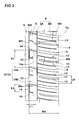
- the compacted snow in the shoulder main groove 3 is subjected to shear in the tire circumferential direction by the radially extending edges (shown in Fig. 3 ) of the second block pieces 15B. Further, as the compacted snow in the shoulder main groove 3 is increased in the width and volume by the axially inner shoulder chamfers 16, the shearing force of the compacted snow is increased, therefore, snow performance such as traction on snow and cornering performance on snow can be improved.
- the axial width Wa of the axially inner shoulder chamfer 16 is more than 25 % of the groove width W1 of the shoulder main groove 3, there is a possibility that the ground contacting area of the first block piece 15A is decreased, and the steering stability is deteriorated. Further, as the groove volume of the shoulder main groove 3 is increased, there is a possibility that, during running on dry pavement, air in the shoulder main groove 3 in the ground contacting patch of the tire resonates and noise performance is deteriorated. If the width Wa is less than 5 % of the width W1, an effective shearing force by the radially extending edges of the second block pieces 15B can not be obtained.
- the second block piece 15B can be provided with a chamfer similarly to the axially inner shoulder chamfer 16 as far as the axial width Wa is smaller than that of the axially inner shoulder chamfer 16 and the difference in the axial width Wa is in a range of 5 % to 25 % of the groove width W1 of the shoulder main groove 3.
- the circumferential length of the chamfered part of the second block piece 15B may be not more than 20 % of the circumferential length L2 of the axially inner shoulder chamfer 16 of the first block piece 15A.
- the axially inner shoulder sipe 10 is terminated without reaching to the narrow longitudinal shoulder groove 11 in order to prevent the axially inner part of the shoulder block 9 from being decreased in the rigidity.
- the shortest distance La between the axially inner shoulder sipe and the narrow longitudinal shoulder groove 11 is preferably set in a range of from 5 % to 20 % of the axial width WS of the shoulder block 9, and the groove width W3 of the narrow longitudinal shoulder groove 11 is preferably set in a range of from 5 % to 25 % of the groove width W1 of the shoulder main groove 3.
- the outside portions 8B of the shoulder lateral grooves 8 extend axially outwardly in order to improve snow/ice performance.
- the axially outer shoulder sipes 12 extend axially outwardly from the narrow longitudinal shoulder groove 11 and terminates within the shoulder block 9 without reaching to the tread edge Te.
- two axially outer shoulder sipes 12 are arranged in the tire circumferential direction in parallel with each other in order to increase the edge effect in the tire circumferential direction of the shoulder block 9, while maintaining the rigidity of the shoulder block 9 in its tread edge side.
- the axial length L3 of the axially outer shoulder sipe 12 is set in a range of from 55 % to 75 % of the axial width WS of the shoulder block 9.
- the above-mentioned shoulder blind groove 13 extends axially inwardly from the tread edge Te and terminates without reaching to the narrow longitudinal shoulder groove 11.
- Such shoulder blind groove 13 contributes to obtain a large compacted-snow shearing force without sacrificing the rigidity of the shoulder block 9, and improves the steering stability and the snow/ice performance in good balance.
- the shoulder blind groove 13 is disposed between the two axially outer shoulder sipes 12 in order that two portions 17 formed between the shoulder blind groove 13 and the two axially outer shoulder sipes 12 have even rigidity and the steering stability can be improved.
- the groove width W6 of the shoulder blind groove 13 is set in a range of from 20 % to 40 % of the groove width W1 of the shoulder main groove 3.
- the above-mentioned crown land regions 6 are each provided with crown lateral grooves 20 extending from the center main groove 4 to the shoulder main groove 3. Thereby, the crown land region 6 is divided in the tire circumferential direction into crown blocks 21 in a row as shown in Fig. 4 .
- the crown lateral groove 20 comprises a deep central portion 20A in its length direction, and a shallow end portion 20B disposed on each side of the deep central portion 20A in the length direction and having a groove depth less than that of the deep central portion 20A.
- Such deep central portion 20A helps to increase the compacted-snow shearing force.
- the rigidity of the crown block 21 is maintained in the neighborhood of the shallow end portions 20B, and the edge effect of the crown block 21 is increased. Therefore, snow/ice performance can be improved.
- the axial length L4 of the central portion 20A is preferably set in a range of from 50 % to 70 % of the axial width Wc of the crown block 21
- the groove depth of the shallow end portion 20B is preferably set in a range of from 55 % to 75 % of the groove depth D2 of the deep central portion 20A
- the groove depth D2 of the deep central portion 20A is preferably set in a range of from 60 % to 80 % of the groove depth D1 of the shoulder main groove 3.
- the groove width of the crown lateral groove 20 is constant along the length thereof in order that the edge portions of the crown block 21 abutting on the crown lateral grooves 20 are prevented from being partially decreased in the rigidity, and water in the crown grooves is smoothly led to the main grooves 3 and 4.
- the groove width W7 of the crown lateral groove 20 is set in a range of from 5 % to 15 % of the circumferential length Lc of the crown block 21.
- the inclination angle ⁇ 1 of the crown lateral groove 20 with respect to the tire axial direction is set in a range of from 20 to 40 degrees so that the edge effect can be exerted in the tire circumferential direction and tire axial direction.
- the crown block 21 is provided with a crown traverse sipe 22, an axially inner crown sipe 23 and an axially outer crown sipe 24.
- the crown traverse sipe 22 extends from the center main groove 4 to the shoulder main groove 3 so that the crown block 21 is divided in the tire circumferential direction into block pieces 28 which are a first block piece 28A on one side in the tire circumferential direction (in Fig. 4 , upper side), and a second block piece 28B on the other side in the tire circumferential direction (in Fig. 4 , under side). This (one side and the other side) applies to all of the crown blocks 21 in each crown land region 6.
- the first block piece 28A of the crown block 21 has an axially outer edge abutting on the shoulder main groove 3 which is chamfered to have an axially outer crown chamfer 30.
- the second block piece 28B of the crown block 21 has an axially outer edge abutting on the shoulder main groove 3 which is not chamfered in this embodiment.
- the axially outer crown chamfer 30 is a substantially flat surface tilted axially inwardly (away from the center of the shoulder main groove 3) and intersecting with the ground contacting top surface of the crown block 21 so as to form an angled corner (slightly larger than 90 degrees) having an edge.
- the axially outer crown chamfer 30 is formed along the substantially entire length of the axially outer edge of the first block piece 28A abutting on the shoulder main groove 3. In this embodiment, therefore, the axially outer crown chamfer 30 extends from the crown lateral groove 20 to the crown traverse sipe 22.
- the axial width wb of the axially outer crown chamfer 30 is preferably set in a range of from 80 % to 120 % of the above-mentioned axial width Wa of the axially inner shoulder chamfer 16.
- the circumferential length L6 of the axially outer crown chamfer 30 is preferably set in a range of from 80 % to 120 % the circumferential length L2 of the axially inner shoulder chamfer 16.
- the depth of the axially outer crown chamfer 30 measured in the tire radial direction from the upper edge to the lower edge of the chamfer 30 is preferably set in a range of from 35 % to 55 % of the groove depth D1 of the shoulder main groove 3 similarly to the depth Da of the axially inner shoulder chamfer 16.
- the axially outer crown chamfer 30 has an partial overlap (hereinafter, the first partial overlap 32) with the above-mentioned axially inner shoulder chamfer 16 in the tire circumferential direction.
- the first partial overlap 32 increases the groove width of the shoulder main groove 3. Such increased groove width can increase the compacted-snow shearing force, therefore, snow performance can be improved.
- the circumferential length L5 of the first partial overlap 32 is preferably set in a range of not less than 3 % of the circumferential length Lc of the crown block 21. If the circumferential length L5 of the first partial overlap 32 is increased, as the shoulder main groove 3 becomes wide as a whole, there is a possibility that the shoulder main groove 3 generates air resonance sound when running on dry pavement and noise performance is deteriorated. Therefore, it is preferable that the circumferential length L5 of the first partial overlap 32 is not more than 15 % of the circumferential length Lc of the crown block 21.
- the first partial overlap 32 is formed between the crown lateral groove 20 and the axially inner shoulder sipe 10.
- the second block piece 28B of the crown block 21 has an axially inner edge abutting on the center main groove 4 which is chamfered to have an axially inner crown chamfer 34
- the first block piece 28A of the crown block 21 has an axially inner edge abutting on the center main groove 4 which is not chamfered. It is however also possible that the axially inner edge of the first block piece 28A is chamfered as far as the axial width of the chamfer is less than that of the axially inner crown chamfer 34.
- the second block pieces 28B with the axially inner crown chamfer 34 and the first block pieces 28A with no chamfer or less chamfer are alternately arranged in the tire circumferential direction.
- the radially extending edges of first block piece 28A abutting on the center main groove 4 can exert edge effect on the compacted snow in the center main groove 4.
- the axially inner crown chamfer 34 is formed along the substantially entire length of the axially inner edge of the second block piece 28B of the crown block 21 as shown in Fig. 4 . In this embodiment, therefore, the axially inner crown chamfer 34 extends from the crown traverse sipe 22 to the crown lateral groove 20.
- the axial width wd of the axially inner crown chamfer 34 is preferably set in a range of from 80 % to 120 % of the axial width Wa of the axially inner shoulder chamfer 16.
- the depth of the axially inner crown chamfer 34 measured in the tire radial direction from the upper edge to the lower edge of the chamfer 34 is preferably set in a range of from 35 % to 55 % of the groove depth of the center main groove 4.
- the circumferential length L9 of the axially inner crown chamfer 34 is preferably set in a range of from 80 % to 120 % of the circumferential length L6 of the axially outer crown chamfer 30.
- each of the axially inner crown chamfers 34 on one side of the center main groove 4 has a partial overlap (hereinafter, the second partial overlap 37) in the tire circumferential direction with one of the axially inner crown chamfers 34 on the other side of the center main groove 4.
- the second partial overlap 37 increase the groove width of the center main groove 4. Such increased groove width can increase the compacted-snow shearing force, therefore, snow performance can be improved.
- the circumferential length L8 of the second partial overlap 37 is set in a range of from 2 % to 12 % of the circumferential length Lc of the crown block 21. If the circumferential length L8 is less than 2 % of the circumferential length Lc, it is difficult to increase the compacted-snow shearing force. If the circumferential length L8 is more than 12 % of the circumferential length Lc, as the center main groove 4 becomes wide as a whole, there is a possibility that the center main groove 4 generates air resonance sound when running on dry pavement and noise performance is deteriorated.
- the circumferential length L8 of the second partial overlap 37 is preferably set to be less than the circumferential length L5 of the first partial overlap 32.
- the crown traverse sipe 22 is zigzag in order to make it possible to exert an edge effect in multi directions to improve snow/ice performance.
- the crown traverse sipe 22 comprises
- the angle ⁇ 3 between the gently inclined part 25 and the steeply inclined part 26 is preferably set to be not less than 90 degrees.
- the angle ⁇ 3 is preferably not more than 150 degrees, more preferably not more than 140 degrees.
- the inclination angle ⁇ 1 of the gently inclined part 25 with respect to the tire axial direction is preferably set in a range of from 10 degrees to 50 degrees.
- the inclination angle ⁇ 2 of the steeply inclined part 26 with respect to the tire axial direction is preferably set in a range of not less than 80 degrees.
- the above-mentioned axially inner crown sipe 23 is disposed on the first block piece 28A.
- the axially inner crown sipe 23 extends axially outwardly from the center main groove 4 and terminates within the first block piece 28A in order to increase the edge effect without deteriorating the rigidity of the first block piece 28A.
- the above-mentioned axially outer crown sipe 24 is disposed on the second block piece 28B.
- the axially outer crown sipe 24 extends axially inwardly from the shoulder main groove 3 and terminates within the second block piece 28B in order to increase the edge effect without deteriorating the rigidity of the second block piece 28B.
- the axially inner crown sipes 23 and the axially outer crown sipes 24 are inclined with respect to the tire axial direction to one direction opposite to the overall inclining direction of the crown traverse sipes 22 with respect to the tire axial direction in order to secure the stability during running straight on snowy/icy roads.
- the axially inner crown sipe 23 and the axially outer crown sipe 24 are arranged substantially in line, and the inner end 24e of the axially outer crown sipe 24 is positioned on an axially outward extension of the axially inner crown sipe 23.
- the axial length L10 of the axially inner crown sipe 23 and the axial length L11 of the axially outer crown sipe 24 are preferably set in a range of from 15 % to 35 % of the axial width Wc of the crown block 21.
- pneumatic tires of size 195/65R15 (rim size: 5.5x15J) having specifications listed in Table 1 were experimentally manufactured, and tested for the snow/ice performance, steering stability and noise performance.
- Embodiment tires were improved in the snow/ice performance, steering stability and noise performance in good balance.
Landscapes
- Engineering & Computer Science (AREA)
- Mechanical Engineering (AREA)
- Tires In General (AREA)
Applications Claiming Priority (1)
| Application Number | Priority Date | Filing Date | Title |
|---|---|---|---|
| JP2014242158A JP6082378B2 (ja) | 2014-11-28 | 2014-11-28 | 空気入りタイヤ |
Publications (2)
| Publication Number | Publication Date |
|---|---|
| EP3025879A1 true EP3025879A1 (fr) | 2016-06-01 |
| EP3025879B1 EP3025879B1 (fr) | 2017-08-16 |
Family
ID=54540971
Family Applications (1)
| Application Number | Title | Priority Date | Filing Date |
|---|---|---|---|
| EP15194300.8A Active EP3025879B1 (fr) | 2014-11-28 | 2015-11-12 | Pneumatique |
Country Status (4)
| Country | Link |
|---|---|
| US (1) | US10266012B2 (fr) |
| EP (1) | EP3025879B1 (fr) |
| JP (1) | JP6082378B2 (fr) |
| CN (1) | CN105644273B (fr) |
Cited By (2)
| Publication number | Priority date | Publication date | Assignee | Title |
|---|---|---|---|---|
| EP3330104A1 (fr) * | 2016-12-02 | 2018-06-06 | Sumitomo Rubber Industries, Ltd. | Pneumatique |
| CN110214091A (zh) * | 2017-02-02 | 2019-09-06 | 横滨橡胶株式会社 | 充气轮胎 |
Families Citing this family (31)
| Publication number | Priority date | Publication date | Assignee | Title |
|---|---|---|---|---|
| USD782961S1 (en) * | 2015-06-10 | 2017-04-04 | Bridgestone Corporation | Tread portion of an automobile tire |
| JP1539609S (fr) * | 2015-06-10 | 2015-12-07 | ||
| USD792330S1 (en) * | 2015-08-31 | 2017-07-18 | Nokian Tyres Plc | Tyre |
| USD779414S1 (en) * | 2015-09-16 | 2017-02-21 | Shandong Hongsheng Rubber Co., Ltd. | Tyre |
| JP6534905B2 (ja) * | 2015-10-14 | 2019-06-26 | Toyo Tire株式会社 | 空気入りタイヤ |
| JP6617512B2 (ja) * | 2015-10-14 | 2019-12-11 | 住友ゴム工業株式会社 | 空気入りタイヤ |
| EP3176006B1 (fr) * | 2015-11-24 | 2018-06-20 | Sumitomo Rubber Industries Limited | Pneumatique |
| USD791063S1 (en) * | 2015-12-03 | 2017-07-04 | The Goodyear Tire & Rubber Company | Tire |
| USD798227S1 (en) * | 2015-12-17 | 2017-09-26 | Bridgestone Americas Tire Operations, Llc | Tire tread |
| JP6668782B2 (ja) * | 2016-01-26 | 2020-03-18 | 住友ゴム工業株式会社 | タイヤ |
| JP6627554B2 (ja) * | 2016-02-15 | 2020-01-08 | 住友ゴム工業株式会社 | 空気入りタイヤ |
| JP6404263B2 (ja) * | 2016-05-20 | 2018-10-10 | 株式会社ニューギン | 遊技機 |
| JP6754675B2 (ja) * | 2016-11-11 | 2020-09-16 | Toyo Tire株式会社 | 空気入りタイヤ |
| JP6822095B2 (ja) * | 2016-11-24 | 2021-01-27 | 住友ゴム工業株式会社 | タイヤ |
| JP6885713B2 (ja) * | 2016-11-25 | 2021-06-16 | Toyo Tire株式会社 | 空気入りタイヤ |
| JP6848583B2 (ja) * | 2017-03-24 | 2021-03-24 | 住友ゴム工業株式会社 | タイヤ |
| US10836215B2 (en) * | 2017-06-27 | 2020-11-17 | Sumitomo Rubber Industries, Ltd. | Tire |
| JP7069995B2 (ja) * | 2018-04-10 | 2022-05-18 | 住友ゴム工業株式会社 | タイヤ |
| EP3489037B1 (fr) * | 2017-11-27 | 2020-08-26 | Sumitomo Rubber Industries Limited | Pneumatique |
| EP3489036B1 (fr) * | 2017-11-27 | 2020-05-20 | Sumitomo Rubber Industries Ltd. | Pneumatique |
| JP6993203B2 (ja) * | 2017-12-13 | 2022-02-10 | Toyo Tire株式会社 | 空気入りタイヤ |
| JP7140570B2 (ja) * | 2018-06-29 | 2022-09-21 | Toyo Tire株式会社 | 空気入りタイヤ |
| JP7183747B2 (ja) * | 2018-12-03 | 2022-12-06 | 住友ゴム工業株式会社 | タイヤ |
| JP7181073B2 (ja) * | 2018-12-14 | 2022-11-30 | Toyo Tire株式会社 | 空気入りタイヤ |
| JP7225871B2 (ja) * | 2019-02-06 | 2023-02-21 | 住友ゴム工業株式会社 | タイヤ |
| WO2020171226A1 (fr) * | 2019-02-22 | 2020-08-27 | 横浜ゴム株式会社 | Pneumatique |
| JP7121695B2 (ja) * | 2019-06-19 | 2022-08-18 | 株式会社ブリヂストン | タイヤ |
| US11472232B2 (en) | 2019-12-18 | 2022-10-18 | The Goodyear Tire & Rubber Company | Tire with tread elements including dual angled chamfer |
| JP2022033505A (ja) | 2020-08-17 | 2022-03-02 | Toyo Tire株式会社 | 空気入りタイヤ |
| JP2022056696A (ja) * | 2020-09-30 | 2022-04-11 | 横浜ゴム株式会社 | タイヤ |
| US20220144018A1 (en) * | 2020-11-06 | 2022-05-12 | The Goodyear Tire & Rubber Company | Tire with one or more recesses in the lateral grooves of at least one shoulder portion |
Citations (4)
| Publication number | Priority date | Publication date | Assignee | Title |
|---|---|---|---|---|
| DE19711607A1 (de) * | 1996-03-29 | 1997-12-18 | Semperit Reifen | Fahrzeugluftreifen |
| JP2002059711A (ja) * | 2000-08-22 | 2002-02-26 | Sumitomo Rubber Ind Ltd | 空気入りタイヤ |
| EP1459908A1 (fr) * | 2003-03-20 | 2004-09-22 | Continental Aktiengesellschaft | Bande de roulement pour pneumatique d'hiver |
| WO2015011964A1 (fr) * | 2013-07-23 | 2015-01-29 | 横浜ゴム株式会社 | Pneu |
Family Cites Families (16)
| Publication number | Priority date | Publication date | Assignee | Title |
|---|---|---|---|---|
| JPS624608A (ja) * | 1985-06-28 | 1987-01-10 | Yokohama Rubber Co Ltd:The | 空気入りタイヤ |
| US4690189A (en) * | 1986-01-29 | 1987-09-01 | The Goodyear Tire & Rubber Company | All-season pneumatic tire with chamfered tread blocks |
| JPS63125410A (ja) * | 1986-11-12 | 1988-05-28 | Yokohama Rubber Co Ltd:The | 雪氷路用タイヤ |
| US6112787A (en) * | 1996-07-04 | 2000-09-05 | Sumito Rubber Industries, Ltd. | Heavy duty pneumatic tire including narrow rib |
| JP4020280B2 (ja) * | 1998-06-22 | 2007-12-12 | 東洋ゴム工業株式会社 | 空気入りラジアルタイヤ |
| DE50012536D1 (de) * | 2000-12-12 | 2006-05-18 | Continental Ag | Fahrzeugreifen mit Laufflächenprofil für guten Schnee- und Eisgriff |
| US6983777B2 (en) * | 2002-10-15 | 2006-01-10 | The Goodyear Tire & Rubber Company | Tire tread with multi-planar chamfers |
| JP3678727B2 (ja) * | 2003-01-07 | 2005-08-03 | 住友ゴム工業株式会社 | 空気入りタイヤ |
| US20100154951A1 (en) * | 2006-01-17 | 2010-06-24 | Bridgestone Corporation | Pneumatic tire |
| US20080271826A1 (en) * | 2007-05-03 | 2008-11-06 | Paul Bryan Maxwell | Pnuematic tire |
| JP2010012978A (ja) | 2008-07-04 | 2010-01-21 | Bridgestone Corp | 空気入りタイヤ |
| JP5149957B2 (ja) * | 2010-12-14 | 2013-02-20 | 住友ゴム工業株式会社 | 空気入りタイヤ |
| JP5146564B2 (ja) * | 2011-05-10 | 2013-02-20 | 横浜ゴム株式会社 | 空気入りタイヤ |
| JP5786964B2 (ja) * | 2012-11-15 | 2015-09-30 | 横浜ゴム株式会社 | 空気入りタイヤ |
| JP5715655B2 (ja) * | 2013-03-22 | 2015-05-13 | 住友ゴム工業株式会社 | 空気入りタイヤ |
| JP6089946B2 (ja) * | 2013-05-13 | 2017-03-08 | 横浜ゴム株式会社 | 空気入りタイヤ |
-
2014
- 2014-11-28 JP JP2014242158A patent/JP6082378B2/ja active Active
-
2015
- 2015-11-06 US US14/934,342 patent/US10266012B2/en active Active
- 2015-11-12 CN CN201510770954.5A patent/CN105644273B/zh active Active
- 2015-11-12 EP EP15194300.8A patent/EP3025879B1/fr active Active
Patent Citations (4)
| Publication number | Priority date | Publication date | Assignee | Title |
|---|---|---|---|---|
| DE19711607A1 (de) * | 1996-03-29 | 1997-12-18 | Semperit Reifen | Fahrzeugluftreifen |
| JP2002059711A (ja) * | 2000-08-22 | 2002-02-26 | Sumitomo Rubber Ind Ltd | 空気入りタイヤ |
| EP1459908A1 (fr) * | 2003-03-20 | 2004-09-22 | Continental Aktiengesellschaft | Bande de roulement pour pneumatique d'hiver |
| WO2015011964A1 (fr) * | 2013-07-23 | 2015-01-29 | 横浜ゴム株式会社 | Pneu |
Cited By (3)
| Publication number | Priority date | Publication date | Assignee | Title |
|---|---|---|---|---|
| EP3330104A1 (fr) * | 2016-12-02 | 2018-06-06 | Sumitomo Rubber Industries, Ltd. | Pneumatique |
| US11001102B2 (en) | 2016-12-02 | 2021-05-11 | Sumitomo Rubber Industries, Ltd. | Tire |
| CN110214091A (zh) * | 2017-02-02 | 2019-09-06 | 横滨橡胶株式会社 | 充气轮胎 |
Also Published As
| Publication number | Publication date |
|---|---|
| CN105644273A (zh) | 2016-06-08 |
| JP6082378B2 (ja) | 2017-02-15 |
| JP2016101886A (ja) | 2016-06-02 |
| US10266012B2 (en) | 2019-04-23 |
| EP3025879B1 (fr) | 2017-08-16 |
| CN105644273B (zh) | 2019-05-10 |
| US20160152087A1 (en) | 2016-06-02 |
Similar Documents
| Publication | Publication Date | Title |
|---|---|---|
| EP3025879B1 (fr) | Pneumatique | |
| US10286732B2 (en) | Tire | |
| EP3000621B1 (fr) | Pneumatique | |
| US8783312B2 (en) | Pneumatic tire | |
| EP3081397B1 (fr) | Pneumatique | |
| EP2239153B1 (fr) | Pneu | |
| US11198330B2 (en) | Tire | |
| EP2952362B1 (fr) | Pneumatique | |
| EP2578418B1 (fr) | Pneu | |
| US9421826B2 (en) | Pneumatic tire | |
| EP2511107B1 (fr) | Pneu | |
| US9085201B2 (en) | Pneumatic tire | |
| US10836215B2 (en) | Tire | |
| EP2767415B1 (fr) | Pneu | |
| EP3093162A1 (fr) | Pneumatique | |
| EP2759417B1 (fr) | Pneu | |
| EP3015288B1 (fr) | Pneumatique | |
| US10864775B2 (en) | Tire | |
| US20160193883A1 (en) | Heavy duty pneumatic tire | |
| EP3025878B1 (fr) | Pneu pour poids lourd | |
| EP3031624B1 (fr) | Pneumatique | |
| EP3925796B1 (fr) | Pneu |
Legal Events
| Date | Code | Title | Description |
|---|---|---|---|
| PUAI | Public reference made under article 153(3) epc to a published international application that has entered the european phase |
Free format text: ORIGINAL CODE: 0009012 |
|
| AK | Designated contracting states |
Kind code of ref document: A1 Designated state(s): AL AT BE BG CH CY CZ DE DK EE ES FI FR GB GR HR HU IE IS IT LI LT LU LV MC MK MT NL NO PL PT RO RS SE SI SK SM TR |
|
| AX | Request for extension of the european patent |
Extension state: BA ME |
|
| 17P | Request for examination filed |
Effective date: 20160826 |
|
| RBV | Designated contracting states (corrected) |
Designated state(s): AL AT BE BG CH CY CZ DE DK EE ES FI FR GB GR HR HU IE IS IT LI LT LU LV MC MK MT NL NO PL PT RO RS SE SI SK SM TR |
|
| GRAP | Despatch of communication of intention to grant a patent |
Free format text: ORIGINAL CODE: EPIDOSNIGR1 |
|
| RAP1 | Party data changed (applicant data changed or rights of an application transferred) |
Owner name: SUMITOMO RUBBER INDUSTRIES, LTD. |
|
| INTG | Intention to grant announced |
Effective date: 20170515 |
|
| GRAS | Grant fee paid |
Free format text: ORIGINAL CODE: EPIDOSNIGR3 |
|
| GRAA | (expected) grant |
Free format text: ORIGINAL CODE: 0009210 |
|
| AK | Designated contracting states |
Kind code of ref document: B1 Designated state(s): AL AT BE BG CH CY CZ DE DK EE ES FI FR GB GR HR HU IE IS IT LI LT LU LV MC MK MT NL NO PL PT RO RS SE SI SK SM TR |
|
| REG | Reference to a national code |
Ref country code: GB Ref legal event code: FG4D |
|
| REG | Reference to a national code |
Ref country code: CH Ref legal event code: EP |
|
| REG | Reference to a national code |
Ref country code: IE Ref legal event code: FG4D |
|
| REG | Reference to a national code |
Ref country code: AT Ref legal event code: REF Ref document number: 918677 Country of ref document: AT Kind code of ref document: T Effective date: 20170915 |
|
| REG | Reference to a national code |
Ref country code: DE Ref legal event code: R096 Ref document number: 602015004145 Country of ref document: DE |
|
| REG | Reference to a national code |
Ref country code: FR Ref legal event code: PLFP Year of fee payment: 3 |
|
| REG | Reference to a national code |
Ref country code: NL Ref legal event code: MP Effective date: 20170816 |
|
| REG | Reference to a national code |
Ref country code: LT Ref legal event code: MG4D |
|
| REG | Reference to a national code |
Ref country code: AT Ref legal event code: MK05 Ref document number: 918677 Country of ref document: AT Kind code of ref document: T Effective date: 20170816 |
|
| PG25 | Lapsed in a contracting state [announced via postgrant information from national office to epo] |
Ref country code: SE Free format text: LAPSE BECAUSE OF FAILURE TO SUBMIT A TRANSLATION OF THE DESCRIPTION OR TO PAY THE FEE WITHIN THE PRESCRIBED TIME-LIMIT Effective date: 20170816 Ref country code: LT Free format text: LAPSE BECAUSE OF FAILURE TO SUBMIT A TRANSLATION OF THE DESCRIPTION OR TO PAY THE FEE WITHIN THE PRESCRIBED TIME-LIMIT Effective date: 20170816 Ref country code: AT Free format text: LAPSE BECAUSE OF FAILURE TO SUBMIT A TRANSLATION OF THE DESCRIPTION OR TO PAY THE FEE WITHIN THE PRESCRIBED TIME-LIMIT Effective date: 20170816 Ref country code: NO Free format text: LAPSE BECAUSE OF FAILURE TO SUBMIT A TRANSLATION OF THE DESCRIPTION OR TO PAY THE FEE WITHIN THE PRESCRIBED TIME-LIMIT Effective date: 20171116 Ref country code: FI Free format text: LAPSE BECAUSE OF FAILURE TO SUBMIT A TRANSLATION OF THE DESCRIPTION OR TO PAY THE FEE WITHIN THE PRESCRIBED TIME-LIMIT Effective date: 20170816 Ref country code: NL Free format text: LAPSE BECAUSE OF FAILURE TO SUBMIT A TRANSLATION OF THE DESCRIPTION OR TO PAY THE FEE WITHIN THE PRESCRIBED TIME-LIMIT Effective date: 20170816 |
|
| PG25 | Lapsed in a contracting state [announced via postgrant information from national office to epo] |
Ref country code: GR Free format text: LAPSE BECAUSE OF FAILURE TO SUBMIT A TRANSLATION OF THE DESCRIPTION OR TO PAY THE FEE WITHIN THE PRESCRIBED TIME-LIMIT Effective date: 20171117 Ref country code: LV Free format text: LAPSE BECAUSE OF FAILURE TO SUBMIT A TRANSLATION OF THE DESCRIPTION OR TO PAY THE FEE WITHIN THE PRESCRIBED TIME-LIMIT Effective date: 20170816 Ref country code: RS Free format text: LAPSE BECAUSE OF FAILURE TO SUBMIT A TRANSLATION OF THE DESCRIPTION OR TO PAY THE FEE WITHIN THE PRESCRIBED TIME-LIMIT Effective date: 20170816 Ref country code: IS Free format text: LAPSE BECAUSE OF FAILURE TO SUBMIT A TRANSLATION OF THE DESCRIPTION OR TO PAY THE FEE WITHIN THE PRESCRIBED TIME-LIMIT Effective date: 20171216 Ref country code: ES Free format text: LAPSE BECAUSE OF FAILURE TO SUBMIT A TRANSLATION OF THE DESCRIPTION OR TO PAY THE FEE WITHIN THE PRESCRIBED TIME-LIMIT Effective date: 20170816 Ref country code: BG Free format text: LAPSE BECAUSE OF FAILURE TO SUBMIT A TRANSLATION OF THE DESCRIPTION OR TO PAY THE FEE WITHIN THE PRESCRIBED TIME-LIMIT Effective date: 20171116 Ref country code: PL Free format text: LAPSE BECAUSE OF FAILURE TO SUBMIT A TRANSLATION OF THE DESCRIPTION OR TO PAY THE FEE WITHIN THE PRESCRIBED TIME-LIMIT Effective date: 20170816 |
|
| PG25 | Lapsed in a contracting state [announced via postgrant information from national office to epo] |
Ref country code: DK Free format text: LAPSE BECAUSE OF FAILURE TO SUBMIT A TRANSLATION OF THE DESCRIPTION OR TO PAY THE FEE WITHIN THE PRESCRIBED TIME-LIMIT Effective date: 20170816 Ref country code: RO Free format text: LAPSE BECAUSE OF FAILURE TO SUBMIT A TRANSLATION OF THE DESCRIPTION OR TO PAY THE FEE WITHIN THE PRESCRIBED TIME-LIMIT Effective date: 20170816 Ref country code: CZ Free format text: LAPSE BECAUSE OF FAILURE TO SUBMIT A TRANSLATION OF THE DESCRIPTION OR TO PAY THE FEE WITHIN THE PRESCRIBED TIME-LIMIT Effective date: 20170816 |
|
| REG | Reference to a national code |
Ref country code: DE Ref legal event code: R097 Ref document number: 602015004145 Country of ref document: DE |
|
| PG25 | Lapsed in a contracting state [announced via postgrant information from national office to epo] |
Ref country code: IT Free format text: LAPSE BECAUSE OF FAILURE TO SUBMIT A TRANSLATION OF THE DESCRIPTION OR TO PAY THE FEE WITHIN THE PRESCRIBED TIME-LIMIT Effective date: 20170816 Ref country code: EE Free format text: LAPSE BECAUSE OF FAILURE TO SUBMIT A TRANSLATION OF THE DESCRIPTION OR TO PAY THE FEE WITHIN THE PRESCRIBED TIME-LIMIT Effective date: 20170816 Ref country code: SK Free format text: LAPSE BECAUSE OF FAILURE TO SUBMIT A TRANSLATION OF THE DESCRIPTION OR TO PAY THE FEE WITHIN THE PRESCRIBED TIME-LIMIT Effective date: 20170816 Ref country code: SM Free format text: LAPSE BECAUSE OF FAILURE TO SUBMIT A TRANSLATION OF THE DESCRIPTION OR TO PAY THE FEE WITHIN THE PRESCRIBED TIME-LIMIT Effective date: 20170816 |
|
| PLBE | No opposition filed within time limit |
Free format text: ORIGINAL CODE: 0009261 |
|
| STAA | Information on the status of an ep patent application or granted ep patent |
Free format text: STATUS: NO OPPOSITION FILED WITHIN TIME LIMIT |
|
| PG25 | Lapsed in a contracting state [announced via postgrant information from national office to epo] |
Ref country code: MC Free format text: LAPSE BECAUSE OF FAILURE TO SUBMIT A TRANSLATION OF THE DESCRIPTION OR TO PAY THE FEE WITHIN THE PRESCRIBED TIME-LIMIT Effective date: 20170816 |
|
| 26N | No opposition filed |
Effective date: 20180517 |
|
| PG25 | Lapsed in a contracting state [announced via postgrant information from national office to epo] |
Ref country code: SI Free format text: LAPSE BECAUSE OF FAILURE TO SUBMIT A TRANSLATION OF THE DESCRIPTION OR TO PAY THE FEE WITHIN THE PRESCRIBED TIME-LIMIT Effective date: 20170816 Ref country code: LU Free format text: LAPSE BECAUSE OF NON-PAYMENT OF DUE FEES Effective date: 20171112 |
|
| REG | Reference to a national code |
Ref country code: BE Ref legal event code: MM Effective date: 20171130 |
|
| REG | Reference to a national code |
Ref country code: IE Ref legal event code: MM4A |
|
| PG25 | Lapsed in a contracting state [announced via postgrant information from national office to epo] |
Ref country code: MT Free format text: LAPSE BECAUSE OF NON-PAYMENT OF DUE FEES Effective date: 20171112 |
|
| REG | Reference to a national code |
Ref country code: FR Ref legal event code: PLFP Year of fee payment: 4 |
|
| PG25 | Lapsed in a contracting state [announced via postgrant information from national office to epo] |
Ref country code: IE Free format text: LAPSE BECAUSE OF NON-PAYMENT OF DUE FEES Effective date: 20171112 |
|
| PG25 | Lapsed in a contracting state [announced via postgrant information from national office to epo] |
Ref country code: BE Free format text: LAPSE BECAUSE OF NON-PAYMENT OF DUE FEES Effective date: 20171130 |
|
| PG25 | Lapsed in a contracting state [announced via postgrant information from national office to epo] |
Ref country code: HU Free format text: LAPSE BECAUSE OF FAILURE TO SUBMIT A TRANSLATION OF THE DESCRIPTION OR TO PAY THE FEE WITHIN THE PRESCRIBED TIME-LIMIT; INVALID AB INITIO Effective date: 20151112 |
|
| REG | Reference to a national code |
Ref country code: CH Ref legal event code: PL |
|
| PG25 | Lapsed in a contracting state [announced via postgrant information from national office to epo] |
Ref country code: CH Free format text: LAPSE BECAUSE OF NON-PAYMENT OF DUE FEES Effective date: 20181130 Ref country code: LI Free format text: LAPSE BECAUSE OF NON-PAYMENT OF DUE FEES Effective date: 20181130 |
|
| PG25 | Lapsed in a contracting state [announced via postgrant information from national office to epo] |
Ref country code: CY Free format text: LAPSE BECAUSE OF FAILURE TO SUBMIT A TRANSLATION OF THE DESCRIPTION OR TO PAY THE FEE WITHIN THE PRESCRIBED TIME-LIMIT Effective date: 20170816 |
|
| PG25 | Lapsed in a contracting state [announced via postgrant information from national office to epo] |
Ref country code: MK Free format text: LAPSE BECAUSE OF FAILURE TO SUBMIT A TRANSLATION OF THE DESCRIPTION OR TO PAY THE FEE WITHIN THE PRESCRIBED TIME-LIMIT Effective date: 20170816 |
|
| PG25 | Lapsed in a contracting state [announced via postgrant information from national office to epo] |
Ref country code: TR Free format text: LAPSE BECAUSE OF FAILURE TO SUBMIT A TRANSLATION OF THE DESCRIPTION OR TO PAY THE FEE WITHIN THE PRESCRIBED TIME-LIMIT Effective date: 20170816 |
|
| PG25 | Lapsed in a contracting state [announced via postgrant information from national office to epo] |
Ref country code: PT Free format text: LAPSE BECAUSE OF FAILURE TO SUBMIT A TRANSLATION OF THE DESCRIPTION OR TO PAY THE FEE WITHIN THE PRESCRIBED TIME-LIMIT Effective date: 20170816 |
|
| PG25 | Lapsed in a contracting state [announced via postgrant information from national office to epo] |
Ref country code: HR Free format text: LAPSE BECAUSE OF FAILURE TO SUBMIT A TRANSLATION OF THE DESCRIPTION OR TO PAY THE FEE WITHIN THE PRESCRIBED TIME-LIMIT Effective date: 20170816 |
|
| PG25 | Lapsed in a contracting state [announced via postgrant information from national office to epo] |
Ref country code: AL Free format text: LAPSE BECAUSE OF FAILURE TO SUBMIT A TRANSLATION OF THE DESCRIPTION OR TO PAY THE FEE WITHIN THE PRESCRIBED TIME-LIMIT Effective date: 20170816 |
|
| GBPC | Gb: european patent ceased through non-payment of renewal fee |
Effective date: 20191112 |
|
| PG25 | Lapsed in a contracting state [announced via postgrant information from national office to epo] |
Ref country code: GB Free format text: LAPSE BECAUSE OF NON-PAYMENT OF DUE FEES Effective date: 20191112 |
|
| P01 | Opt-out of the competence of the unified patent court (upc) registered |
Effective date: 20230510 |
|
| PGFP | Annual fee paid to national office [announced via postgrant information from national office to epo] |
Ref country code: FR Payment date: 20230929 Year of fee payment: 9 |
|
| PGFP | Annual fee paid to national office [announced via postgrant information from national office to epo] |
Ref country code: DE Payment date: 20230929 Year of fee payment: 9 |